Embed Size (px)
Citation preview

OPTIONS AND PLANNING DIMENSIONS
KONE TravelMaster™ 115 inclined autowalks

Well designed and manufactured escalators and autowalks are a must for today’s highly demanding public areas. They are key to ensuring the smooth, effi cient and safe fl ow of people traveling within a building’s environment.
KONE prides itself on delivering the ‘low risk’ option to customers. We offer ‘peace of mind’ in terms of product design, customer support and project management, combined with the highest levels of effi ciency and safety during the installation phase.
The versatile KONE TravelMaster escalator and autowalk range is ideal for new installations, and incorporates two specifi c models:n TravelMaster 110 escalator
n TravelMaster 115 inclined autowalk
They are specifi cally designed to meet the exact demands and needs of the commercial market sector,whether it’s a low rise escalator you are looking for, or an inclined autowalk.
KONE TRANSITMASTER™ PRODUCT RANGE
2

The KONE TravelMaster 115 is a commercial inclined autowalk targeted primarily towards the retail segment – supermarkets, hypermarkets, department stores and shopping centers. Here it is part of the total KONE solution offering together with other KONE products such as:
n Commercial escalators ------------------------- e.g. KONE TravelMaster™ 110n Passenger elevators ----------------------------- e.g. KONE MonoSpace®
n Goods elevators --------------------------------- e.g. KONE TranSys™
n Scenic elevators ---------------------------------- based on KONE MonoSpace® or KONE MonoSpace® Specialn Modernization solutions ----------------------- e.g. KONE EcoMod™ 2n Automatic building doors
Secondary focus areas for the KONE TravelMaster 115 include airports, smaller railway stations, hotels and hospitals.
The KONE TravelMaster 115 is designed, from both a technical and visual point of view, to fulfill the main customer requirements of the target segments:
n Cost competitivenessn High quality in terms of technical performance and visual appearancen Large standard offering with some engineering flexibilityn Elegant and modern design
KONE TRAVELMASTER 115 BASIC DATA
Inclination 10°, 11° , 12°
Horizontal pallets (bottom/top) 0/1, 1/1, 0/2, 1/2, 2/2
Transition radii 6000 mm at top end, 0 mm at bottom end for 0 horizontal pallet (10,000 mm for 1 or 2 horizontal pallets)
Maximum rise 8 m
Operational environment Indoor, semi-outdoor
Pallet width 800 mm, 1000 mm , 1100 mm
Balustrade type • 10 mm tempered glass with slim handrail profile• Stainless steel sandwich panel balustrade• Balustrade extension of 400 or 700 mm
Balustrade height 1000 mm, 1100 mm
Speed 0.4 m/s with inverter, 0.5 m/s
Truss type Standard or flat design
Pallet chains Inside roller chains
Duty cycle 12 – 16 hours/day
Typical service life 100,000 hours*
TRAVELMASTER™ 115 – A NEW LEVEL OF SHOPPING COMFORT
Overview of technical specifications
* Actual service life is directly related to operation hours and load profile. Contact your KONE representative for more information
3

ECO-EFFICIENCYKONE firmly believes that sustainable buildings are our future. We are committed to helping customers achieve their environmental objectives by providing environmentally responsible products and services.
Cladding
Access cover
Skirting
Comb
n Various LED lighting solutions allows an energy saving of up to 80% compared to conventional lighting.
n Regenerative solutions recover energy created when the autowalk is used and feed it back into the system.
n All of our production operations are certified according to the ISO 14001 standard.
n Stand-by speed operation reduces the inclined autowalk speed when no passengers are traveling, thus further reducing energy consumption and increasing equipment lifetime.
n The availability of a lubrication-free step chain means no oil, a cleaner inclined autowalk and environment, reduced fire hazard, simpler cleaning and easier maintenance.
n Reduced autowalk running speed of 0.4 m/s not only enhances passenger safety but also saves energy depending on passenger traffic.
4

The standard safety features of the KONE TravelMaster 115 according to the EN 115-1:2008 + A1:2010 safety code are the following:
n Emergency stop buttons for passengers in the top left and bottom right handrail inlet front plates
n Auxiliary brake is standard for units above 6 m vertical rise and is available as an option for units below 6 m
n Broken pallet chain (chain tension) switches in the return station which stop the autowalk in case of failure of the pallet chain
n Handrail inlet switches with contacts at the handrail inlets into the balustrade heads
n Comb plate impact device switches which stop the autowalk in case objects become trapped between the comb teeth and the moving pallet band
n Pallet sag switches, which stop the autowalk if a pallet sags by more than 5 mm before it enters the comb
n Pallet band locking device
n Step guards at top & bottom
n Speed sensor system, which electronically monitors the motor for over/under speeds and pallet band reversal
n Motor thermal protection for temperature monitoring
n Main switch with thermal and magnetic release
n Stop switches for engineers’ use within upper and lower end pits
n Sockets for inspection use installed in the upper and lower machine compartments
n Skirt deflector brushes
n Access cover contacts
n Handrail speed monitor
n Missing pallet monitor
n Diagnostic display
n Additional emergency stop button
Balustrade
Handrail
Pallet
Decking
Frontplate
Other safety and monitoring functions, such as KONE Remote Monitoring and E-link, are available on request.
SAFETY OPTIONS
5

Aluminum comb segments Aluminum comb segments with yellow coating
COMB
Black plasticSatin polished stainless steel
VISUAL OPTIONSACCESS COVER
FRONTPLATESKIRT BRUSH HOLDER
Stainless steel without coating Sheet steel skirt with black powder coating
Clear anodized aluminum
Sheet steel with black anti-friction coating
Black anodized aluminum
Stainless steel with clear anti-friction coating
SKIRT
Stainless steel surface with punched diamond pattern (available in 304# and 443#)
Black painted stainless steel surface with punched diamond pattern (available in 304# and 443#). Floor numbering is available.
Natural ribbed aluminum Ribbed aluminum with black grooves
6

Clear glass balustrade panels Stainless steel sandwich panels
BALUSTRADE
HANDRAIL
Black
Green
Black with white demarcation inserts
Brown
Red Blue
Beige Grey
Passenger fall protection barrierheight up to 1300 mm.Recommended when a fall greater than 6 m is possible
DECKING
Natural anodized aluminum Brushed satin stainless steel Center decking in same material as decking
7

CLADDING
Grey primed sheet steel cladding (RAL7036)
Note: If needed this can be used for local on site decoration.
Brushed satin stainless steel cladding
Grey powder coated sheet steel cladding (RAL7036)
Note: If required, KONE can supply mounting strips for local customized cladding. Maximum weight allowance = 15 kg/m2.
ADDITIONAL OPTIONS
Diagnostic displayAnti-climb barrier (EN115-1:2008 + A1:2010 requirement)
Additional emergency stop button (EN115-1:2008:+A1:2010 requirement)
Silver aluminumNatural aluminum Black stainless steel pallet (only for selected markets)
Yellow painted demarcation on two sides of pallet
Yellow plastic inserts demarcation on two sides of pallet (only with black stainless steel pallet)
Black aluminum pallets with metal color ribs
PALLET
PALLET DEMARCATION
HORIZONTAL PALLETS
1 horizontal pallet 2 horizontal pallets
Note: Different combinations of horizontal pallet between lower end and upper end are available for you to select: 0 lower end + 1 upper end
1 lower end + 1 upper end 0 lower end + 2 upper end1 lower end + 2 upper end2 lower end + 2 upper end
8
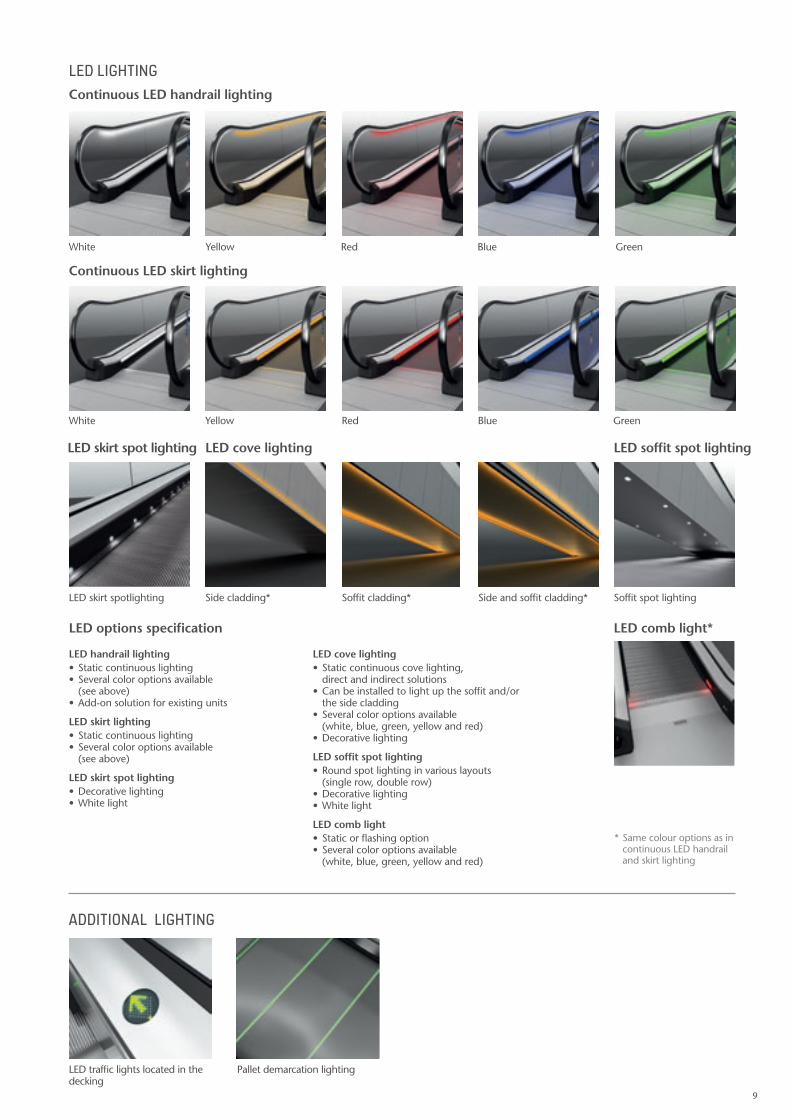
LED cove lighting • Static continuous cove lighting, direct and indirect solutions• Can be installed to light up the soffit and/or the side cladding• Several color options available (white, blue, green, yellow and red) • Decorative lighting
LED soffit spot lighting• Round spot lighting in various layouts (single row, double row)• Decorative lighting• White light
LED comb light• Static or flashing option • Several color options available (white, blue, green, yellow and red)
LED handrail lighting • Static continuous lighting • Several color options available (see above)• Add-on solution for existing units
LED skirt lighting• Static continuous lighting• Several color options available (see above)
LED skirt spot lighting• Decorative lighting• White light
LED LIGHTING
ADDITIONAL LIGHTING
LED skirt spotlighting
White
White
Side cladding*
Yellow
Yellow
Soffit cladding*
Red
Red
Side and soffit cladding*
Blue
Blue
Green
Green
Soffit spot lighting
Pallet demarcation lightingLED traffic lights located in the decking
LED options specification
Continuous LED handrail lighting
Continuous LED skirt lighting
LED soffit spot lighting
LED comb light*
LED cove lightingLED skirt spot lighting
* Same colour options as in continuous LED handrail and skirt lighting
9

Architectural planning data
KONE TRAVELMASTER™ 115 PLANNING DIMENSIONS10°/ 11°/ 12° inclination / standard truss type / 1 horizontal pallet at upper landingCode: EN 115-1:2008 + A1:20101)
Passenger Circulation Area Requirements
1500
min
.250
0
2845m
in.2
000
[1304]
[2448]
Detail Y (Mirror image of X)
200
130
Autowalk
40
Steel plate KONE
Adjusting plate
Face of structure
Steel plateRubber By
Permanent elasticjoint by others
floor levelFinished
Safety fence
1) Other local codes dimensional requirements are available upon request, please contact your local KONE Sales representative for more information.
11391040958
944*863**795***
188*188**188***
6220*5665**5200***
1000
1050
Passenger Circulation Area Requirements
1304*1502**1610***
min
.250
0
min
.200
0
Detail Y (Mirror image of X)
220
138
Autowalk
40
Steel plate KONE
Adjusting plate
Face of structure
Steel plateRubber By
Permanent elasticjoint by others
floor levelFinished
2448*2844**3060***
Passenger Circulation Area Requirements
1304*1502**1610***
min
.250
0
min
.200
0
Detail Y (Mirror image of X)
22013
8
Autowalk
40
Steel plate KONE
Adjusting plate
Face of structure
Steel plateRubber By
Permanent elasticjoint by others
floor levelFinished
2448*2844**3060***
REACTION FORCE (KN)
800 mm pallet width 1000 mm pallet width 1100 mm pallet width
Without intermediate support R1=5.0L/1000+10.9 R1=5.0L/1000+3.0 R1=5.5L/1000+12 R1=5.5L/1000+3.4 R1=5.7L/1000+12.5 R1=5.7L/1000+3.6
With intermediate support R1=2.1L/1000+10.9 R1=2.1L/1000+3.0 R1=2.3L/1000+12 R1=2.3L/1000+3.4 R1=2.4L/1000+12.5 R1=2.4L/1000+3.6
Rm = 5.9L/1000+3.0 Rm = 6.6L/1000 Rm = 6.9L/1000
* a = 5.671*H ** a = 5.145*H *** a = 4.705*H
L = AA + BB + a
Railing by others
10

n All dimensions are in millimeters
n Maximum vertical rise: H = 8000 mm
n One intermediate support needed if span >18110 mm
n Upper truss extension maximum 500 mm
n Lower truss extension maximum 500 mm
n Additional cladding material maximum 15 kg/m2
n Dimension for 10o inclination *
n Dimension for 11o inclination **
n Dimension for 12o inclination ***
10°/ 11°/ 12° inclination / standard truss type / 1 horizontal pallet at upper landingCode: EN 115-1:2008 + A1:20101)
Passenger Circulation Area Requirements
1500
min
.250
0
2845
min
.200
0
[1304]
[2448]
Detail Y (Mirror image of X)
200
130
Autowalk
40
Steel plate KONE
Adjusting plate
Face of structure
Steel plateRubber By
Permanent elasticjoint by others
floor levelFinished
Safety fence
Passenger Circulation Area Requirements
1500
min
.250
0
2845
min
.200
0
[1304]
[2448]
Detail Y (Mirror image of X)
200
130
Autowalk
40
Steel plate KONE
Adjusting plate
Face of structure
Steel plateRubber By
Permanent elasticjoint by others
floor levelFinished
Safety fence
Note: If you would like to obtain the exact dimensions for your specific project, we recommend you use the Escalator Design Tools, which can be found on www.kone.com.
2588*2359**2168***
1100
1144*1342**1450***
1452*1650**1758***
1149*1347**1455*** 145
1349*1547**1655***
800*1000**1100***
1312*1510**1618***
145
Lifting holes distance
Handrail outer edge distance
Width of truss
Width of pit
Width of pallet
Width of autowalkPallet width:800*1000**1100***
620* 620** 620***
861
1861
11

Architectural planning data
KONE TRAVELMASTER™ 115 PLANNING DIMENSIONS10°/ 11°/ 12° inclination / standard truss type/ 1 horizontal pallet at each landingCode: EN 115-1:2008 + 1:20101)
Passenger Circulation Area Requirements
1500
min
.250
0
2845
min
.200
0
[1304]
[2448]
Detail Y (Mirror image of X)
200
130
Autowalk
40
Steel plate KONE
Adjusting plate
Face of structure
Steel plateRubber By
Permanent elasticjoint by others
floor levelFinished
B-B
3011*2744**2522***
8290*7545**6930***
1100
1150
1) Other local codes dimensional requirements are available upon request, please contact your local KONE Sales representative for more information.
Passenger Circulation Area Requirements
1304*1502**1610***
min
.250
0
min
.200
0
Detail Y (Mirror image of X)
220
138
Autowalk
40
Steel plate KONE
Adjusting plate
Face of structure
Steel plateRubber By
Permanent elasticjoint by others
floor levelFinished
2448*2844**3060***
Passenger Circulation Area Requirements
1304*1502**1610***
min
.250
0
min
.200
0
Detail Y (Mirror image of X)
22013
8
Autowalk
40
Steel plate KONE
Adjusting plate
Face of structure
Steel plateRubber By
Permanent elasticjoint by others
floor levelFinished
2448*2844**3060***
REACTION FORCE (KN)
800 mm pallet width 1000 mm pallet width 1100 mm pallet width
Without intermediate support R1=5.0L/1000+10.9 R1=5.0L/1000+3.0 R1=5.5L/1000+12 R1=5.5L/1000+3.4 R1=5.7L/1000+12.5 R1=5.7L/1000+3.6
With intermediate support R1=2.1L/1000+10.9 R1=2.1L/1000+3.0 R1=2.3L/1000+12 R1=2.3L/1000+3.4 R1=2.4L/1000+12.5 R1=2.4L/1000+3.6
Rm = 5.9L/1000+3.0 Rm = 6.6L/1000 Rm = 6.9L/1000
620*620**620***
* a = 5.671*H ** a = 5.145*H *** a = 4.705*H
L = AA + BB + a
Railing by others
12

n All dimensions are in millimeters
n Maximum vertical rise: H = 8000 mm
n One intermediate support needed if span >18110 mm
n Upper truss extension maximum 500 mm
n Lower truss extension maximum 500 mm
n Additional cladding material maximum 15 kg/m2
n Dimension for 10o inclination *
n Dimension for 11o inclination **
n Dimension for 12o inclination ***
Passenger Circulation Area Requirements
1500
min
.250
0
2845
min
.200
0
[1304]
[2448]
Detail Y (Mirror image of X)
200
130
Autowalk
40
Steel plate KONE
Adjusting plate
Face of structure
Steel plateRubber By
Permanent elasticjoint by others
floor levelFinished
B-B
Note: If you would like to obtain the exact dimensions for your specific project, we recommend you use the Escalator Design Tools, which can be found on www.kone.com.
2588*2359**2168***
1100
Passenger Circulation Area Requirements
1500
min
.250
0
2845
min
.200
0
[1304]
[2448]
Detail Y (Mirror image of X)
200
130
Autowalk
40
Steel plate KONE
Adjusting plate
Face of structure
Steel plateRubber By
Permanent elasticjoint by others
floor levelFinished
B-B
1144*1342**1450***
1452*1650**1758***
1149*1347**1455*** 1451349*1547**1655***
800*1000**1100***
1312*1510**1618***
145
Lifting holes distance
Handrail outer edge distance
Width of pallet
Width of truss
Width of pit
Safety fence
Width of autowalkPallet width:800*1000**1100*** 620*
620** 620***
861
1861
13

Architectural planning data
KONE TRAVELMASTER™ 115 PLANNING DIMENSIONS10°/ 11°/ 12° inclination / standard truss type / 2 horizontal pallets at upper landingCode: EN 115-1:2008 + A1:20101)
Passenger Circulation Area Requirements
1500
min
.250
0
2845
min
.200
0
[1304]
[2448]
Detail Y (Mirror image of X)
200
130
Autowalk
40
Steel plate KONE
Adjusting plate
Face of structure
Steel plateRubber By
Permanent elasticjoint by others
floor levelFinished
944* 863** 795***
6220*5665**5200***
1000
1050
1) Other local codes dimensional requirements are available upon request, please contact your local KONE Sales representative for more information.
Passenger Circulation Area Requirements
1304*1502**1610***
min
.250
0
min
.200
0
Detail Y (Mirror image of X)
220
138
Autowalk
40
Steel plate KONE
Adjusting plate
Face of structure
Steel plateRubber By
Permanent elasticjoint by others
floor levelFinished
2448*2844**3060***
Passenger Circulation Area Requirements
1304*1502**1610***
min
.250
0
min
.200
0
Detail Y (Mirror image of X)
22013
8
Autowalk
40
Steel plate KONE
Adjusting plate
Face of structure
Steel plateRubber By
Permanent elasticjoint by others
floor levelFinished
2448*2844**3060***
640
REACTION FORCE (KN)
800 mm pallet width 1000 mm pallet width 1100 mm pallet width
Without intermediate support R1=5.0L/1000+10.9 R1=5.0L/1000+3.0 R1=5.5L/1000+12 R1=5.5L/1000+3.4 R1=5.7L/1000+12.5 R1=5.7L/1000+3.6
With intermediate support R1=2.1L/1000+10.9 R1=2.1L/1000+3.0 R1=2.3L/1000+12 R1=2.3L/1000+3.4 R1=2.4L/1000+12.5 R1=2.4L/1000+3.6
Rm = 5.9L/1000+3.0 Rm = 6.6L/1000 Rm = 6.9L/1000
188*188**188***
* a = 5.671*H ** a = 5.145*H *** a = 4.705*H
L = AA + BB + a
Railing by others
14
All dimensions are in millimeters
Maximum vertical rise: H = 8000 mm
One intermediate support needed if span >18110 mm
n Upper truss extension maximum 500 mm
n Lower truss extension maximum 500 mm
n Additional cladding material maximum 15 kg/m2
n Dimension for 10o inclination *
n Dimension for 11o inclination **
n Dimension for 12o inclination ***
Passenger Circulation Area Requirements
1500
min
.250
0
2845
min
.200
0
[1304]
[2448]
Detail Y (Mirror image of X)
200
130
Autowalk
40
Steel plate KONE
Adjusting plate
Face of structure
Steel plateRubber By
Permanent elasticjoint by others
floor levelFinished
Note: If you would like to obtain the exact dimensions for your specific project, we recommend you use the Escalator Design Tools, which can be found on www.kone.com.
3028*2759**2535***
1100
Passenger Circulation Area Requirements
1500
min
.250
0
2845
min
.200
0
[1304]
[2448]
Detail Y (Mirror image of X)
200
130
Autowalk
40
Steel plate KONE
Adjusting plate
Face of structure
Steel plateRubber By
Permanent elasticjoint by others
floor levelFinished
1349*1547**1655***
800*1000**1100***
1144*1342**1450***
1312*1510**1618***1452*1650**1758***
1149*1347**1455*** 145145
Lifting holes distance
Width of autowalk
Width of pallet
Pallet width:800*1000**1100***
Handrail outer edge distance
Width of truss
Width of pit
Safety fence
620* 620** 620***
861
1861
15
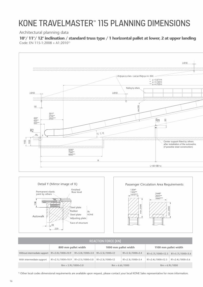
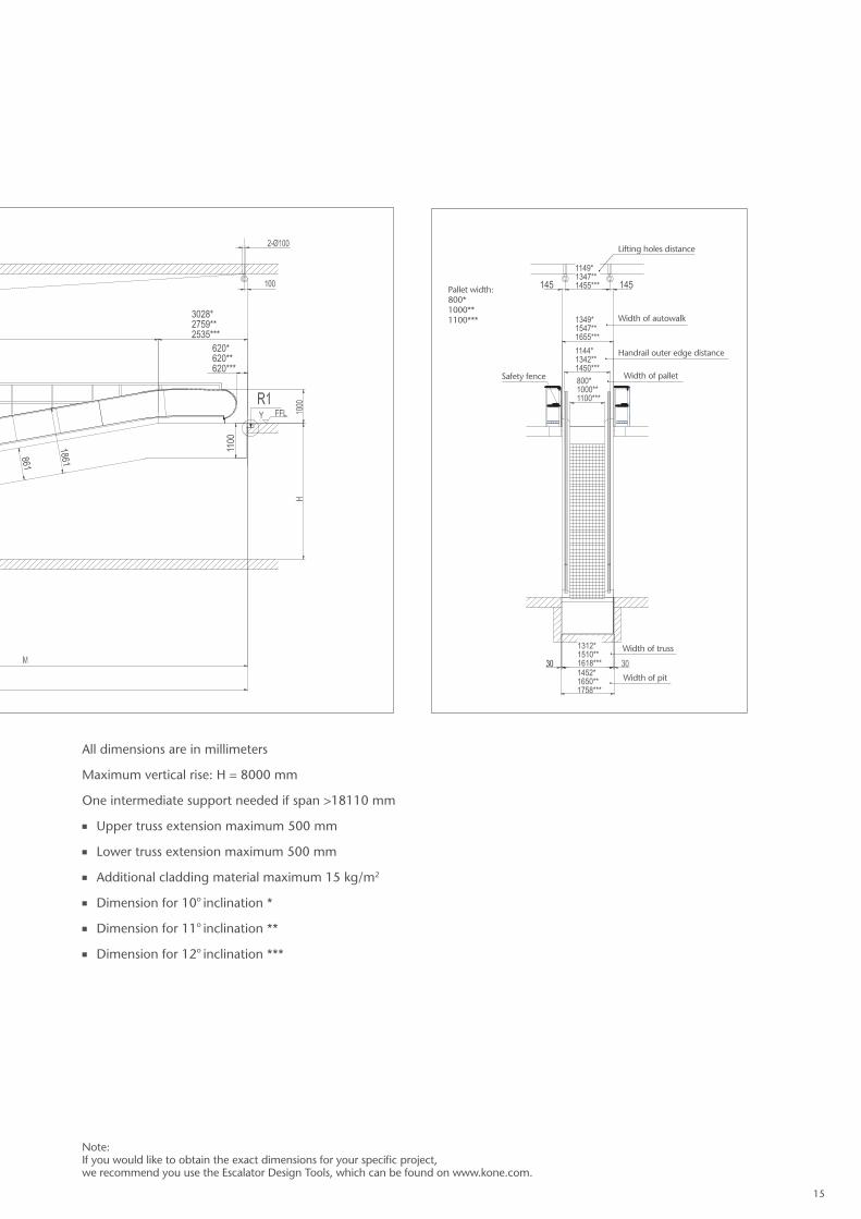
10°/ 11°/ 12° inclination / standard truss type / 1 horizontal pallet at lower, 2 at upper landing Code: EN 115-1:2008 + A1:20101)
Architectural planning data
KONE TRAVELMASTER™ 115 PLANNING DIMENSIONS
Passenger Circulation Area Requirements
1500
min
.250
0
2845
min
.200
0
[1304]
[2448]
Detail Y (Mirror image of X)
200
130
Autowalk
40
Steel plate KONE
Adjusting plate
Face of structure
Steel plateRubber By
Permanent elasticjoint by others
floor levelFinished
3011*2744**2522***
8290*7545**6930***
1100
1150
1) Other local codes dimensional requirements are available upon request, please contact your local KONE Sales representative for more information.
Passenger Circulation Area Requirements
1304*1502**1610***
min
.250
0
min
.200
0
Detail Y (Mirror image of X)
220
138
Autowalk
40
Steel plate KONE
Adjusting plate
Face of structure
Steel plateRubber By
Permanent elasticjoint by others
floor levelFinished
2448*2844**3060***
Passenger Circulation Area Requirements
1304*1502**1610***
min
.250
0
min
.200
0
Detail Y (Mirror image of X)
220
138
Autowalk
40
Steel plate KONE
Adjusting plate
Face of structure
Steel plateRubber By
Permanent elasticjoint by others
floor levelFinished
2448*2844**3060***
REACTION FORCE (KN)
800 mm pallet width 1000 mm pallet width 1100 mm pallet width
Without intermediate support R1=5.0L/1000+10.9 R1=5.0L/1000+3.0 R1=5.5L/1000+12 R1=5.5L/1000+3.4 R1=5.7L/1000+12.5 R1=5.7L/1000+3.6
With intermediate support R1=2.1L/1000+10.9 R1=2.1L/1000+3.0 R1=2.3L/1000+12 R1=2.3L/1000+3.4 R1=2.4L/1000+12.5 R1=2.4L/1000+3.6
Rm = 5.9L/1000+3.0 Rm = 6.6L/1000 Rm = 6.9L/1000
620*620**620***
* a = 5.671*H ** a = 5.145*H *** a = 4.705*H
L = AA + BB + a
Railing by others
16

Passenger Circulation Area Requirements
1500
min
.250
0
2845
min
.200
0
[1304]
[2448]
Detail Y (Mirror image of X)
200
130
Autowalk
40
Steel plate KONE
Adjusting plate
Face of structure
Steel plateRubber By
Permanent elasticjoint by others
floor levelFinished
10°/ 11°/ 12° inclination / standard truss type / 1 horizontal pallet at lower, 2 at upper landing Code: EN 115-1:2008 + A1:20101)
n All dimensions are in millimeters
n Maximum vertical rise: H = 8000 mm
n One intermediate support needed if span >18110 mm
n Upper truss extension maximum 500 mm
n Lower truss extension maximum 500 mm
n Additional cladding material maximum 15 kg/m2
n Dimension for 10o inclination *
n Dimension for 11o inclination **
n Dimension for 12o inclination ***
Passenger Circulation Area Requirements
1500
min
.250
0
2845
min
.200
0
[1304]
[2448]
Detail Y (Mirror image of X)
200
130
Autowalk
40
Steel plate KONE
Adjusting plate
Face of structure
Steel plateRubber By
Permanent elasticjoint by others
floor levelFinished
Note: If you would like to obtain the exact dimensions for your specific project, we recommend you use the Escalator Design Tools, which can be found on www.kone.com.
3028*2759**2535***
1100
1312*1510**1618***1452*1650**1758***
1451451349*1547**1655***
800*1000**1100***
1144*1342**1450***
1149*1347**1455***
Lifting holes distance
Width of pallet
Width of truss
Width of pit
Pallet width:800*1000**1100***
Handrail outer edge distance
Width of autowalk
Safety fence
631* 640** 650***
620* 620** 620***
861
1861
17

10°/ 11°/ 12° inclination / standard truss type / 2 horizontal pallets at each landingCode: EN 115-1:2008 + A1:20101)
KONE TRAVELMASTER™ 115 PLANNING DIMENSIONSArchitectural planning data
Passenger Circulation Area Requirements
1304*1502**1610***
min
.250
0
min
.200
0
Detail Y (Mirror image of X)
220
138
Autowalk
40
Steel plate KONE
Adjusting plate
Face of structure
Steel plateRubber By
Permanent elasticjoint by others
floor levelFinished
2448*2844**3060***
3451*3144**2889***
8730*7945**7295***
1100
1150
1) Other local codes dimensional requirements are available upon request, please contact your local KONE Sales representative for more information.
Passenger Circulation Area Requirements
1304*1502**1610***
min
.250
0
min
.200
0
Detail Y (Mirror image of X)
220
138
Autowalk
40
Steel plate KONE
Adjusting plate
Face of structure
Steel plateRubber By
Permanent elasticjoint by others
floor levelFinished
2448*2844**3060***
Passenger Circulation Area Requirements
1304*1502**1610***
min
.250
0
min
.200
0
Detail Y (Mirror image of X)
22013
8
Autowalk
40
Steel plate KONE
Adjusting plate
Face of structure
Steel plateRubber By
Permanent elasticjoint by others
floor levelFinished
2448*2844**3060***
REACTION FORCE (KN)
800 mm pallet width 1000 mm pallet width 1100 mm pallet width
Without intermediate support R1=5.0L/1000+10.9 R1=5.0L/1000+3.0 R1=5.5L/1000+12 R1=5.5L/1000+3.4 R1=5.7L/1000+12.5 R1=5.7L/1000+3.6
With intermediate support R1=2.1L/1000+10.9 R1=2.1L/1000+3.0 R1=2.3L/1000+12 R1=2.3L/1000+3.4 R1=2.4L/1000+12.5 R1=2.4L/1000+3.6
Rm = 5.9L/1000+3.0 Rm = 6.6L/1000 Rm = 6.9L/1000
620*620**620***
* a = 5.671*H ** a = 5.145*H *** a = 4.705*H
L = AA + BB + a
Railing by others
18

Passenger Circulation Area Requirements
1304*1502**1610***
min
.250
0
min
.200
0
Detail Y (Mirror image of X)
220
138
Autowalk
40
Steel plate KONE
Adjusting plate
Face of structure
Steel plateRubber By
Permanent elasticjoint by others
floor levelFinished
2448*2844**3060***
n All dimensions are in millimeters
n Maximum vertical rise H = 8000 mm
n One intermediate support needed if span >18110 mm
n Upper truss extension maximum 500 mm
n Lower truss extension maximum 500 mm
n Additional cladding material maximum 15 kg/m2
n Dimension for 10o inclination *
n Dimension for 11o inclination **
n Dimension for 12o inclination ***
Passenger Circulation Area Requirements
1304*1502**1610***
min
.250
0
min
.200
0
Detail Y (Mirror image of X)
220
138
Autowalk
40
Steel plate KONE
Adjusting plate
Face of structure
Steel plateRubber By
Permanent elasticjoint by others
floor levelFinished
2448*2844**3060***
Note: If you would like to obtain the exact dimensions for your specific project, we recommend you use the Escalator Design Tools, which can be found on www.kone.com.
3028*2759**2535***
1100
1349*1547***1655***
800*1000**1100***
1144*1342**1450***
1312*1510**1618***1452*1650**1758***
1149*1347**1455*** 145145
Lifting holes distance
Width of pallet
Pallet width:800*1000**1100***
Width of autowalk
Safety fenceHandrail outer edge distance
Width of truss
Width of pit
620* 620** 620***
861
1861
19

Intermediate support fitted by others after installation of the autowalk(if possible steel construction)
HEAD GUARDExtend at least 25 mm below lower edge 25 mm below lower edge of handrail (By Customer)
Safety barriers by others
Distance between supports Distance between supportsDistance between supportsDistance between supports
F-F
D-D
B-B
E-E
Load per lifting hole approx 40-60 KN (by others)
Architectural planning data
KONE TRAVELMASTER™ 115 PLANNING DIMENSIONS10°/ 11°/ 12° inclination / flat truss type / 1 horizontal pallet at upper landingCode: EN 115-1:2008 + A1:20101)
4170* 4000** 3845***
1000
1050
1) Other local codes dimensional requirements are available upon request, please contact your local KONE Sales representative for more information.
Passenger Circulation Area Requirements
1304*1502**1610***
min
.250
0
min
.200
0
Detail Y (Mirror image of X)
220
138
Autowalk
40
Steel plate KONE
Adjusting plate
Face of structure
Steel plateRubber By
Permanent elasticjoint by others
floor levelFinished
2448*2844**3060***
Passenger Circulation Area Requirements
1304*1502**1610***
min
.250
0
min
.200
0
Detail Y (Mirror image of X)
22013
8
Autowalk
40
Steel plate KONE
Adjusting plate
Face of structure
Steel plateRubber By
Permanent elasticjoint by others
floor levelFinished
2448*2844**3060***
REACTION FORCE (KN)
800 mm pallet width 1000 mm pallet width 1100 mm pallet width
Without intermediate support R1=5.0L/1000+10.9 R1=5.0L/1000+3.0 R1=5.5L/1000+12 R1=5.5L/1000+3.4 R1=5.7L/1000+12.5 R1=5.7L/1000+3.6
With intermediate support R1=2.1L/1000+10.9 R1=2.1L/1000+3.0 R1=2.3L/1000+12 R1=2.3L/1000+3.4 R1=2.4L/1000+12.5 R1=2.4L/1000+3.6
Rm = 5.9L/1000+3.0 Rm = 6.6L/1000 Rm = 6.9L/1000
485
10o
11o
12o
944*863**795***
188*188**188***
* a = 5.671*H ** a = 5.145*H *** a = 4.705*H
L = AA + BB + a
20

Intermediate support fitted by others after installation of the autowalk(if possible steel construction)
HEAD GUARDExtend at least 25 mm below lower edge 25 mm below lower edge of handrail (By Customer)
Safety barriers by others
Distance between supports Distance between supportsDistance between supportsDistance between supports
F-F
D-D
B-B
E-E
Load per lifting hole approx 40-60 KN (by others)
n All dimensions are in millimeters
n Maximum vertical rise: H = 8000 mm
n One intermediate support needed if span >10000 mm
n Upper truss extension maximum 500 mm
n Lower truss extension maximum 500 mm
n Additional cladding material maximum 15 kg/m2
n Dimension for 10o inclination *
n Dimension for 11o inclination **
n Dimension for 12o inclination ***
10°/ 11°/ 12° inclination / flat truss type / 1 horizontal pallet at upper landingCode: EN 115-1:2008 + A1:20101)
Note: If you would like to obtain the exact dimensions for your specific project, we recommend you use the Escalator Design Tools, which can be found on www.kone.com.
1100
1349*1547**1655***
800*1000**1100***
1144*1342**1450***
1312*1510**1618***
1452*1650**1758***
145145
Width of autowalk
Lifting holes distance
Safety fence
Handrail outer edge distance
Width of pallet
Width of truss
Width of pit
1149*1347**1455***
Pallet width:800*1000**1100***
2588*2359**2168***
620* 620** 620***
21

Intermediate support fitted by others after installation of the autowalk(if possible steel construction)
HEAD GUARDExtend at least 25 mm below lower edge 25 mm below lower edge of handrail (By Customer)
Safety barriers by others
Distance between supports Distance between supportsDistance between supportsDistance between supports
F-F
D-D
B-B
E-E
Load per lifting hole approx 40-60 KN (by others)
Architectural planning data
KONE TRAVELMASTER™ 115 PLANNING DIMENSIONS10°/ 11°/ 12° inclination / flat truss type/ 1 horizontal pallet at lower, 1 at upper landingCode: EN 115-1:2008 + 1:20101)
3011*2744**2522***
1100
1150
Passenger Circulation Area Requirements
1304*1502**1610***
min
.250
0
min
.200
0
Detail Y (Mirror image of X)
220
138
Autowalk
40
Steel plate KONE
Adjusting plate
Face of structure
Steel plateRubber By
Permanent elasticjoint by others
floor levelFinished
2448*2844**3060***
Passenger Circulation Area Requirements
1304*1502**1610***
min
.250
0
min
.200
0
Detail Y (Mirror image of X)
22013
8
Autowalk
40
Steel plate KONE
Adjusting plate
Face of structure
Steel plateRubber By
Permanent elasticjoint by others
floor levelFinished
2448*2844**3060***
1) Other local codes dimensional requirements are available upon request, please contact your local KONE Sales representative for more information.
6120* 5575** 5120***
REACTION FORCE (KN)
800 mm pallet width 1000 mm pallet width 1100 mm pallet width
Without intermediate support R1=5.0L/1000+10.9 R1=5.0L/1000+3.0 R1=5.5L/1000+12 R1=5.5L/1000+3.4 R1=5.7L/1000+12.5 R1=5.7L/1000+3.6
With intermediate support R1=2.1L/1000+10.9 R1=2.1L/1000+3.0 R1=2.3L/1000+12 R1=2.3L/1000+3.4 R1=2.4L/1000+12.5 R1=2.4L/1000+3.6
Rm = 5.9L/1000+3.0 Rm = 6.6L/1000 Rm = 6.9L/1000
485
10o
11o
12o
620*620**620***
L = AA + BB + a
* a = 5.671*H ** a = 5.145*H *** a = 4.705*H
22

Intermediate support fitted by others after installation of the autowalk(if possible steel construction)
HEAD GUARDExtend at least 25 mm below lower edge 25 mm below lower edge of handrail (By Customer)
Safety barriers by others
Distance between supports Distance between supportsDistance between supportsDistance between supports
F-F
D-D
B-B
E-E
Load per lifting hole approx 40-60 KN (by others)
n All dimensions are in millimeters
n Maximum vertical rise: H = 8000 mm
n One intermediate support needed if span >10000 mm
n Upper truss extension maximum 500 mm
n Lower truss extension maximum 500 mm
n Additional cladding material maximum 15 kg/m2
n Dimension for 10o inclination *
n Dimension for 11o inclination **
n Dimension for 12o inclination ***
10°/ 11°/ 12° inclination / flat truss type/ 1 horizontal pallet at lower, 1 at upper landingCode: EN 115-1:2008 + 1:20101)
Note: If you would like to obtain the exact dimensions for your specific project, we recommend you use the Escalator Design Tools, which can be found on www.kone.com.
2588*2359**2168***
1100
1349*1547**1655***
800*1000**1100***
1144*1342**1450***
1312*1510**1618***
1452*1650**1758***
1149*1347**1455*** 145145
Width of autowalk
Lifting holes distance
Safety fence
Handrail outer edge distance
Width of pallet
Width of truss
Width of pit
Pallet width:800*1000**1100***
620*620**620***
23

Intermediate support fitted by others after installation of the autowalk(if possible steel construction)
HEAD GUARDExtend at least 25 mm below lower edge 25 mm below lower edge of handrail (By Customer)
Safety barriers by others
Distance between supports Distance between supportsDistance between supportsDistance between supports
F-F
D-D
B-B
E-E
Load per lifting hole approx 40-60 KN (by others)
Architectural planning data
KONE TRAVELMASTER™ 115 PLANNING DIMENSIONS10°/ 11°/ 12° inclination / flat truss type / 2 horizontal pallets at upper landingCode: EN 115-1:2008 + A1:20101)
1000
1050
1) Other local codes dimensional requirements are available upon request, please contact your local KONE Sales representative for more information.
Passenger Circulation Area Requirements
1304*1502**1610***
min
.250
0
min
.200
0
Detail Y (Mirror image of X)
220
138
Autowalk
40
Steel plate KONE
Adjusting plate
Face of structure
Steel plateRubber By
Permanent elasticjoint by others
floor levelFinished
2448*2844**3060***
Passenger Circulation Area Requirements
1304*1502**1610***
min
.250
0
min
.200
0
Detail Y (Mirror image of X)
22013
8
Autowalk
40
Steel plate KONE
Adjusting plate
Face of structure
Steel plateRubber By
Permanent elasticjoint by others
floor levelFinished
2448*2844**3060***
REACTION FORCE (KN)
800 mm pallet width 1000 mm pallet width 1100 mm pallet width
Without intermediate support R1=5.0L/1000+10.9 R1=5.0L/1000+3.0 R1=5.5L/1000+12 R1=5.5L/1000+3.4 R1=5.7L/1000+12.5 R1=5.7L/1000+3.6
With intermediate support R1=2.1L/1000+10.9 R1=2.1L/1000+3.0 R1=2.3L/1000+12 R1=2.3L/1000+3.4 R1=2.4L/1000+12.5 R1=2.4L/1000+3.6
Rm = 5.9L/1000+3.0 Rm = 6.6L/1000 Rm = 6.9L/1000
485
10o
11o
12o
4170* 4000** 3845***
944*863**795***
188*188**188***
L = AA + BB + a
* a = 5.671*H ** a = 5.145*H *** a = 4.705*H
* a = 5.671*H ** a = 5.145*H *** a = 4.705*H
24
Intermediate support fitted by others after installation of the autowalk(if possible steel construction)
HEAD GUARDExtend at least 25 mm below lower edge 25 mm below lower edge of handrail (By Customer)
Safety barriers by others
Distance between supports Distance between supportsDistance between supportsDistance between supports
F-F
D-D
B-B
E-E
Load per lifting hole approx 40-60 KN (by others)
n All dimensions are in millimeters
n Maximum vertical rise: H = 8000 mm
n One intermediate support needed if span >10000 mm
n Upper truss extension maximum 500 mm
n Lower truss extension maximum 500 mm
n Additional cladding material maximum 15 kg/m2
n Dimension for 10o inclination *
n Dimension for 11o inclination **
n Dimension for 12o inclination ***
Note: If you would like to obtain the exact dimensions for your specific project, we recommend you use the Escalator Design Tools, which can be found on www.kone.com.
1100
1349*1547**1655***
800*1000**1100***
1144*1342**1450***
1312*1510**1618***
1452*1650**1758***
1149*1347**1455*** 145145
Width of autowalk
Lifting holes distance
Safety fence
Handrail outer edge distance
Width of pallet
Width of truss
Width of pit
640
Pallet width:800*1000**1100***
3028*2759**2535***
620* 620** 620***
25

Intermediate support fitted by others after installation of the autowalk(if possible steel construction)
HEAD GUARDExtend at least 25 mm below lower edge 25 mm below lower edge of handrail (By Customer)
Safety barriers by others
Distance between supports Distance between supportsDistance between supportsDistance between supports
F-F
D-D
B-B
E-E
Load per lifting hole approx 40-60 KN (by others)
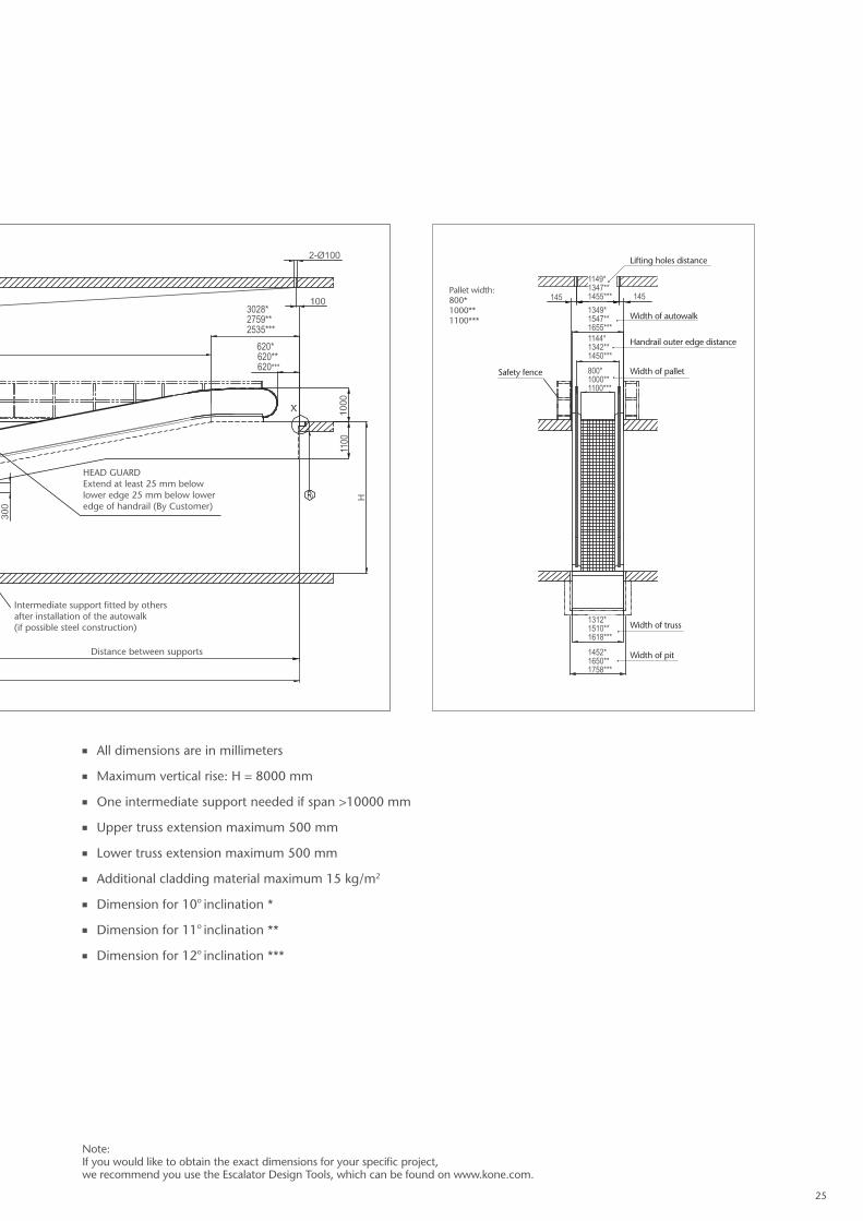
10°/ 11°/ 12° inclination / flat truss type / 1 horizontal pallet at lower, 2 at upper landing Code: EN 115-1:2008 + A1:20101)
Architectural planning data
KONE TRAVELMASTER™ 115 PLANNING DIMENSIONS11
00
1150
1) Other local codes dimensional requirements are available upon request, please contact your local KONE Sales representative for more information.
Passenger Circulation Area Requirements
1304*1502**1610***
min
.250
0
min
.200
0
Detail Y (Mirror image of X)
220
138
Autowalk
40
Steel plate KONE
Adjusting plate
Face of structure
Steel plateRubber By
Permanent elasticjoint by others
floor levelFinished
2448*2844**3060***
Passenger Circulation Area Requirements
1304*1502**1610***
min
.250
0
min
.200
0
Detail Y (Mirror image of X)
22013
8
Autowalk
40
Steel plate KONE
Adjusting plate
Face of structure
Steel plateRubber By
Permanent elasticjoint by others
floor levelFinished
2448*2844**3060***
REACTION FORCE (KN)
800 mm pallet width 1000 mm pallet width 1100 mm pallet width
Without intermediate support R1=5.0L/1000+10.9 R1=5.0L/1000+3.0 R1=5.5L/1000+12 R1=5.5L/1000+3.4 R1=5.7L/1000+12.5 R1=5.7L/1000+3.6
With intermediate support R1=2.1L/1000+10.9 R1=2.1L/1000+3.0 R1=2.3L/1000+12 R1=2.3L/1000+3.4 R1=2.4L/1000+12.5 R1=2.4L/1000+3.6
Rm = 5.9L/1000+3.0 Rm = 6.6L/1000 Rm = 6.9L/1000
485
10o
11o
12o
3011*2744**2522***
6120* 5575** 5120***
620*620**620***
L = AA + BB + aL = AA + BB + a
* a = 5.671*H ** a = 5.145*H *** a = 4.705*H
* a = 5.671*H ** a = 5.145*H *** a = 4.705*H
26

Intermediate support fitted by others after installation of the autowalk(if possible steel construction)
HEAD GUARDExtend at least 25 mm below lower edge 25 mm below lower edge of handrail (By Customer)
Safety barriers by others
Distance between supports Distance between supportsDistance between supportsDistance between supports
F-F
D-D
B-B
E-E
Load per lifting hole approx 40-60 KN (by others)
10°/ 11°/ 12° inclination / flat truss type / 1 horizontal pallet at lower, 2 at upper landing Code: EN 115-1:2008 + A1:20101)
n All dimensions are in millimeters
n Maximum vertical rise: H = 8000 mm
n One intermediate support needed if span >10000 mm
n Upper truss extension maximum 500 mm
n Lower truss extension maximum 500 mm
n Additional cladding material maximum 15 kg/m2
n Dimension for 10o inclination *
n Dimension for 11o inclination **
n Dimension for 12o inclination ***
Note: If you would like to obtain the exact dimensions for your specific project, we recommend you use the Escalator Design Tools, which can be found on www.kone.com.
1100
1349*1547**1655***
800*1000**1100***
1144*1342**1450***
1312*1510**1618***
1452*1650**1758***
1149*1347**1455*** 145145
Width of autowalk
Lifting holes distance
Safety fence
Handrail outer edge distance
Width of pallet
Width of truss
Width of pit
Pallet width:800*1000**1100***
3028*2759**2535***
620*620**620***
27

Intermediate support fitted by others after installation of the autowalk(if possible steel construction)
HEAD GUARDExtend at least 25 mm below lower edge 25 mm below lower edge of handrail (By Customer)
Safety barriers by others
Distance between supports Distance between supportsDistance between supportsDistance between supports
F-F
D-D
B-B
E-E
Load per lifting hole approx 40-60 KN (by others)
10°/ 11°/ 12° inclination / flat truss type / 2 horizontal pallets at lower landing, 2 at upper landingCode: EN 115-1:2008 + A1:20101)
Passenger Circulation Area Requirements
1304*1502**1610***
min
.250
0
min
.200
0
Detail Y (Mirror image of X)
220
138
Autowalk
40
Steel plate KONE
Adjusting plate
Face of structure
Steel plateRubber By
Permanent elasticjoint by others
floor levelFinished
2448*2844**3060***
Passenger Circulation Area Requirements
1304*1502**1610***
min
.250
0
min
.200
0
Detail Y (Mirror image of X)
22013
8
Autowalk
40
Steel plate KONE
Adjusting plate
Face of structure
Steel plateRubber By
Permanent elasticjoint by others
floor levelFinished
2448*2844**3060***
KONE TRAVELMASTER™ 115 PLANNING DIMENSIONSArchitectural planning data
1100
1150
1) Other local codes dimensional requirements are available upon request, please contact your local KONE Sales representative for more information.
REACTION FORCE (KN)
800 mm pallet width 1000 mm pallet width 1100 mm pallet width
Without intermediate support R1=5.0L/1000+10.9 R1=5.0L/1000+3.0 R1=5.5L/1000+12 R1=5.5L/1000+3.4 R1=5.7L/1000+12.5 R1=5.7L/1000+3.6
With intermediate support R1=2.1L/1000+10.9 R1=2.1L/1000+3.0 R1=2.3L/1000+12 R1=2.3L/1000+3.4 R1=2.4L/1000+12.5 R1=2.4L/1000+3.6
Rm = 5.9L/1000+3.0 Rm = 6.6L/1000 Rm = 6.9L/1000
485
10o
11o
12o
3451*3144**2889***
6560* 5975** 5490***
620*620**620***
L = AA + BB + a
* a = 5.671*H ** a = 5.145*H *** a = 4.705*H
28

Intermediate support fitted by others after installation of the autowalk(if possible steel construction)
HEAD GUARDExtend at least 25 mm below lower edge 25 mm below lower edge of handrail (By Customer)
Safety barriers by others
Distance between supports Distance between supportsDistance between supportsDistance between supports
F-F
D-D
B-B
E-E
Load per lifting hole approx 40-60 KN (by others)
n All dimensions are in millimeters
n Maximum vertical rise H = 8000 mm
n One intermediate support needed if span >10000 mm
n Upper truss extension maximum 500 mm
n Lower truss extension maximum 500 mm
n Additional cladding material maximum 15 kg/m2
n Dimension for 10o inclination *
n Dimension for 11o inclination **
n Dimension for 12o inclination ***
Note: If you would like to obtain the exact dimensions for your specific project, we recommend you use the Escalator Design Tools, which can be found on www.kone.com.
1100
1349*1547**1655***
800*1000**1100***
1144*1342**1450***
1312*1510**1618***
1452*1650**1758***
1149*1347**1455*** 145145
Width of autowalk
Lifting holes distance
Safety fence
Handrail outer edge distance
Width of pallet
Width of truss
Width of pit
Pallet width:800*1000**1100***
620*620**620***
3028*2759**2535***
29

30

31

8199
KONE Corporation
www.kone.com
This publication is for general informational purposes only and we reserve the right at any time to alter the product design and specifications. No statement this publication contains shall be construed as a warranty or condition, express or implied, as to any product, its fitness for any particular purpose, merchantability, quality or representation of the terms of any purchase agreement. Minor differences between printed and actual colors may exist. KONE MonoSpace®, KONE EcoDisc®, KONE Care® and People Flow® are registered trademarks of KONE Corporation. Copyright © 2016 KONE Corporation.
KONE provides innovative and eco-efficient
solutions for elevators, escalators, automatic
building doors and the systems that integrate
them with today’s intelligent buildings.
We support our customers every step of the way;
from design, manufacturing and installation
to maintenance and modernization. KONE
is a global leader in helping our customers
manage the smooth flow of people and
goods throughout their buildings.
Our commitment to customers is present in
all KONE solutions. This makes us a reliable
partner throughout the life cycle of the building.
We challenge the conventional wisdom of
the industry. We are fast, flexible, and we have
a well-deserved reputation as a technology leader,
with such innovations as KONE MonoSpace®,
KONE NanoSpace™ and KONE UltraRope®.
KONE employs close to 50,000 dedicated
experts to serve you globally and locally.