Embed Size (px)
Citation preview
AG3000pMechanical Quick Start Guide
253.872.0284 Page 1 of 4 seametrics.com
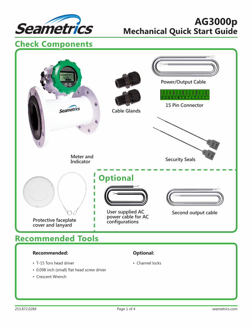
Check Components
Meter and Indicator
Power/Output Cable
15 Pin Connector
Optional
User supplied AC power cable for AC configurations
Second output cable
Recommended ToolsRecommended:
• T-15 Torx head driver
• 0.098 inch (small) flat head screw driver
• Crescent Wrench
Optional:
• Channel locks
Security Seals
Cable Glands
Protective faceplate cover and lanyard
LT-14272r1.4 2016111111/11/16
Seametrics • 19026 72nd Avenue South • Kent, Washington 98032 • USA (P) 253.872.0284 • (F) 253.872.0285 • 1.800.975.8153 • seametrics.com
AG3000pMechanical Quick Start Guide
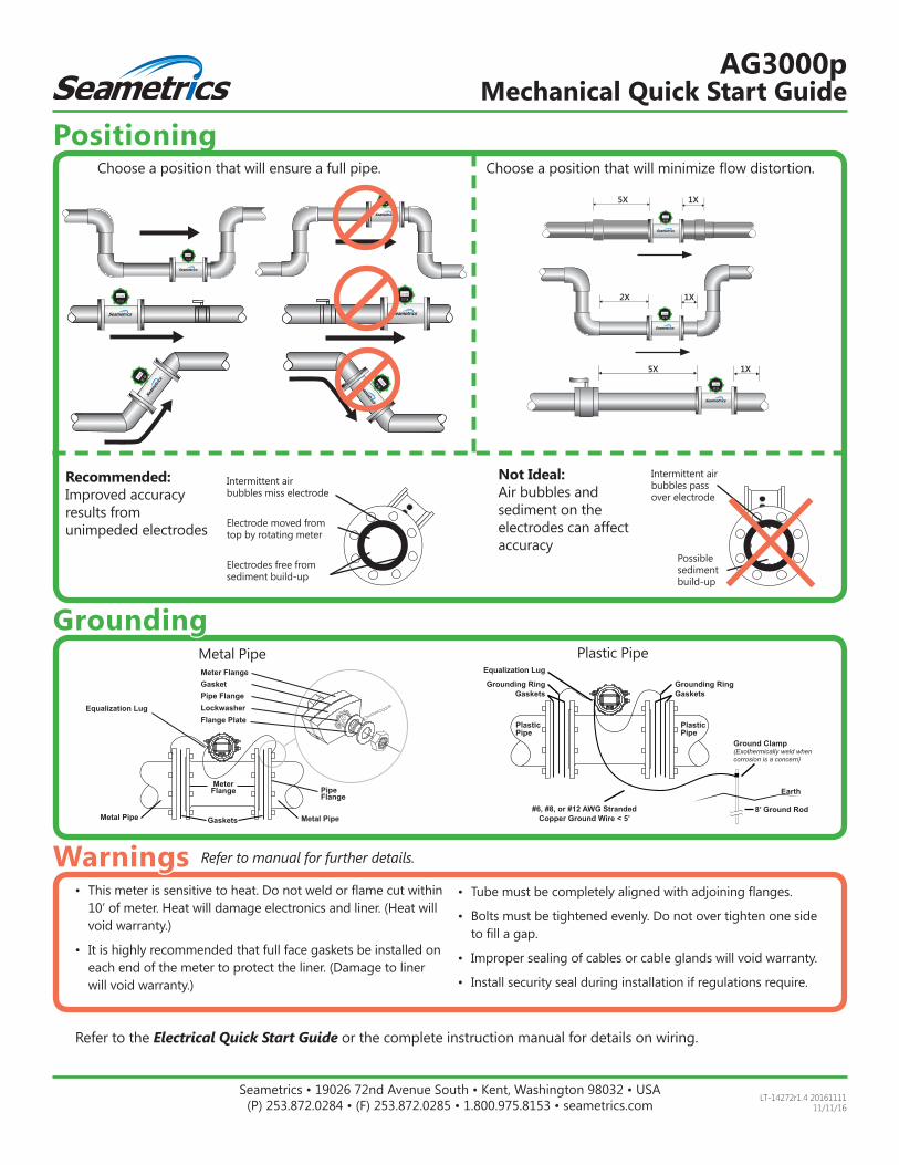
Metal Pipe Plastic Pipe
Choose a position that will ensure a full pipe. Choose a position that will minimize flow distortion.
12345
12345
12345 12345
12345
12345
12345
12345
12345 12345
12345
12345
12345
12345
12345 12345
12345
12345
12345
12345
12345 12345
12345
12345
12345
12345
12345 12345
12345
12345
12345
12345
12345 12345
12345
12345
12345
12345
12345
12345
12345
12345
5X 1X
12345
12345
12345
12345
12345
12345
2X 1X
12345
12345
12345
12345
12345
12345
5X 1X
Positioning
Grounding
Warnings• This meter is sensitive to heat. Do not weld or flame cut within
10’ of meter. Heat will damage electronics and liner. (Heat will void warranty.)
• It is highly recommended that full face gaskets be installed on each end of the meter to protect the liner. (Damage to liner will void warranty.)
• Tube must be completely aligned with adjoining flanges.
• Bolts must be tightened evenly. Do not over tighten one side to fill a gap.
• Improper sealing of cables or cable glands will void warranty.
• Install security seal during installation if regulations require.
Refer to manual for further details.
Not Ideal:Air bubbles and sediment on theelectrodes can affect accuracy
Recommended:Improved accuracy results from unimpeded electrodes Electrode moved from
top by rotating meter
Intermittent airbubbles miss electrode
Electrodes free from sediment build-up
Intermittent airbubbles pass over electrode
Possible sediment build-up
Refer to the Electrical Quick Start Guide or the complete instruction manual for details on wiring.
Equalization Lug
Ground Clamp(Exothermically weld when corrosion is a concern)
8’ Ground Rod
Earth
Grounding RingGaskets
Grounding Ring Gaskets
#6, #8, or #12 AWG Stranded Copper Ground Wire < 5’
PlasticPipe
PlasticPipe
Equalization Lug
Meter Flange Pipe
Flange
GasketPipe Flange
Flange PlateLockwasher
Metal PipeMetal Pipe
Meter Flange
Gaskets