Embed Size (px)
Citation preview
OPTIMUM REFRIGERATION CONTROL WITH E2™
Abtar Singh, Ph.D.
Emerson Climate Technologies 1640 Airport Rd. Suite 105
Kennesaw, GA 30144
OPTIMUM REFRIGERATION CONTROL WITH E2™
ABSTRACT
This article discusses the control of modern supermarket refrigeration systems using state of the art digital refrigeration controllers manufactured and marketed by Computer Process Controls (CPC), under the “E2” name. This family of refrigeration controllers was designed to provide precise refrigerated product temperature control while minimizing refrigeration system energy and maintenance expenses. The E2 controllers, and their predecessors, have been in use in supermarkets throughout the US and world for more than twenty years. The findings outlined below are based on theoretical analysis done using sophisticated refrigeration models developed by Emerson, and include information about energy and product shrink savings that CPC users have experienced since the introduction of these refrigeration controllers to the supermarket industry.
INTRODUCTION
Supermarkets operate on very thin profit margins. Any reductions in energy, maintenance or product shrink expense directly improves supermarket profits. The energy required to refrigerate perishable food products accounts for a substantial portion (more than 30%) of an average supermarket’s total electric energy usage and expense. Installing carefully designed mechanical systems that include efficient compressors, condensers and refrigerated fixtures does not guarantee optimum fixture temperature control, maximum refrigeration system energy efficiency and lowest refrigeration system operating expenses. This is because refrigeration systems seldom run at their design load, and are often ineffective and inefficient at part load conditions. Therefore, matching refrigeration system capacity to the real and varying refrigeration loads found in all supermarkets, and the control systems required to accomplish this task, are the most important factors for high overall refrigeration system performance and low overall refrigeration system operating expenses.
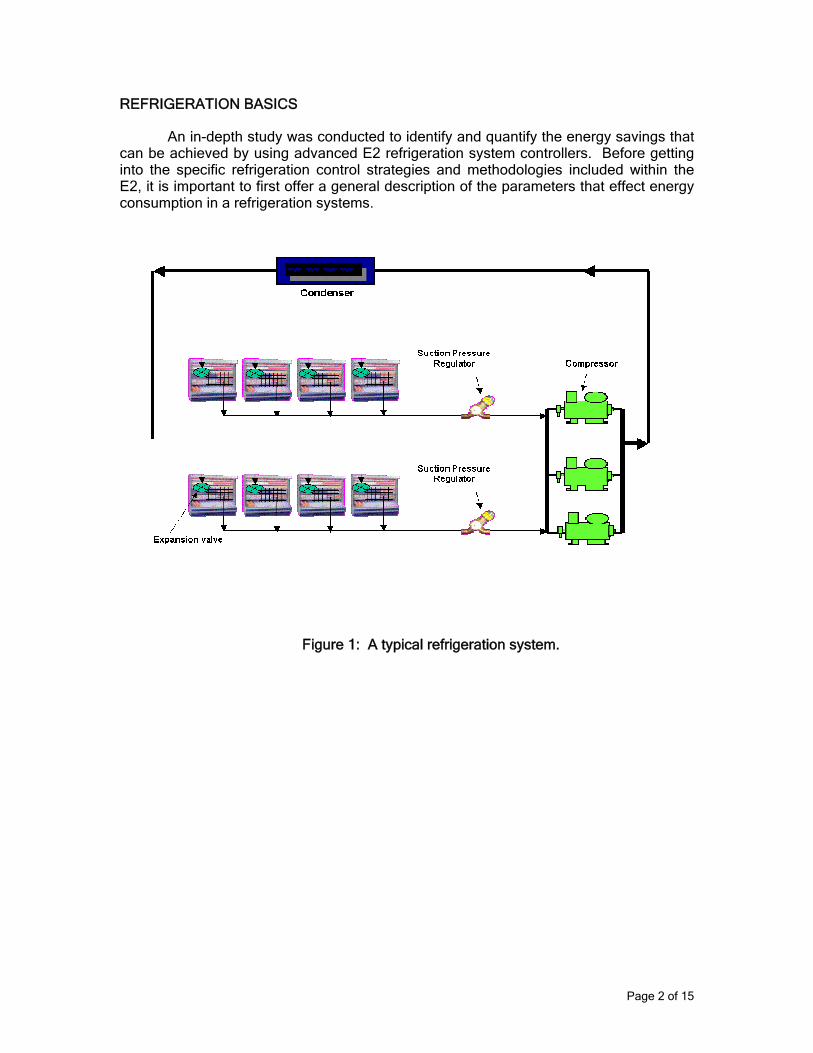
A typical refrigeration system consists of at least one display case with a refrigerant metering device (expansion valve), a compressor, and a condenser (see figure 1). The system may also be fitted with fixture suction pressure regulators between the refrigerated fixture(s) (refrigerated display cases and storage boxes) and compressor(s), as well as other mechanical and electromechanical refrigeration control valves. The primary objective of any refrigeration control system is to achieve the desired fixture and product temperatures. The challenge for refrigeration system designers, manufacturers, and operators is to find effective ways to modulate the system compressors, condenser fans, expansion valves, pressure regulators, and other components to achieve stable and reliable system operation and high system operating efficiencies while at the same time closely controlling refrigerated fixtures and products to these desired temperatures. Defrost and defrost control is also necessary for the operation of any real refrigerated fixture, along with control of anticondensate heaters that are a part of most glass door and some other types of refrigerated display case. The refrigeration system controllers should be able to provide efficient control of these system elements as well.
Page 1 of 15
REFRIGERATION BASICS
An in-depth study was conducted to identify and quantify the energy savings that can be achieved by using advanced E2 refrigeration system controllers. Before getting into the specific refrigeration control strategies and methodologies included within the E2, it is important to first offer a general description of the parameters that effect energy consumption in a refrigeration systems.
Figure 1: A typical refrigeration system.
Page 2 of 15
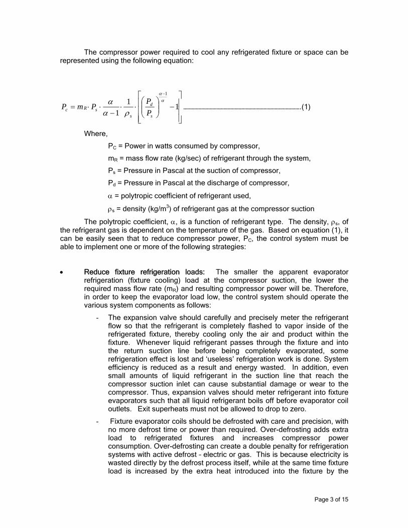
The compressor power required to cool any refrigerated fixture or space can be represented using the following equation:
⎥⎥⎥
⎦
⎤
⎢⎢⎢
⎣
⎡−⎟⎟
⎠
⎞⎜⎜⎝
⎛⋅⋅
−⋅⋅=
−
111
1αα
ραα
s
d
ssRc P
PPmP ………………………………………………………………………….(1)
Where,
PC = Power in watts consumed by compressor,
mR = mass flow rate (kg/sec) of refrigerant through the system,
Ps = Pressure in Pascal at the suction of compressor,
Pd = Pressure in Pascal at the discharge of compressor,
α = polytropic coefficient of refrigerant used,
ρs = density (kg/m3) of refrigerant gas at the compressor suction
The polytropic coefficient, α, is a function of refrigerant type. The density, ρs, of the refrigerant gas is dependent on the temperature of the gas. Based on equation (1), it can be easily seen that to reduce compressor power, PC, the control system must be able to implement one or more of the following strategies:
• Reduce fixture refrigeration loads: The smaller the apparent evaporator refrigeration (fixture cooling) load at the compressor suction, the lower the required mass flow rate (mR) and resulting compressor power will be. Therefore, in order to keep the evaporator load low, the control system should operate the various system components as follows:
- The expansion valve should carefully and precisely meter the refrigerant flow so that the refrigerant is completely flashed to vapor inside of the refrigerated fixture, thereby cooling only the air and product within the fixture. Whenever liquid refrigerant passes through the fixture and into the return suction line before being completely evaporated, some refrigeration effect is lost and ‘useless’ refrigeration work is done. System efficiency is reduced as a result and energy wasted. In addition, even small amounts of liquid refrigerant in the suction line that reach the compressor suction inlet can cause substantial damage or wear to the compressor. Thus, expansion valves should meter refrigerant into fixture evaporators such that all liquid refrigerant boils off before evaporator coil outlets. Exit superheats must not be allowed to drop to zero.
- Fixture evaporator coils should be defrosted with care and precision, with no more defrost time or power than required. Over-defrosting adds extra load to refrigerated fixtures and increases compressor power consumption. Over-defrosting can create a double penalty for refrigeration systems with active defrost – electric or gas. This is because electricity is wasted directly by the defrost process itself, while at the same time fixture load is increased by the extra heat introduced into the fixture by the
Page 3 of 15
extended defrost. Additional refrigeration energy then has to be expended to remove this extra heat.
• Reduce return gas temperature: Based on equation (1), lower suction return gas temperature results in higher density gas and hence lower compressor power. Too high a return gas superheat is therefore as bad as too low a return gas superheat. This is a second consequence and benefit of accurate metering of liquid refrigerant into the evaporators by expansion valves - resulting low return gas temperatures and “superheat” (increases in return gas temperature above the saturation temperature of the suction gas). Compressor volumetric efficiency is increased by the lower temperature and higher density suction gas flow. This also suggests that suction lines should always be insulated, so that suction return gas does not gain unwanted heat from the ambient, thereby avoiding ‘useless’ or ‘parasitic’ heat load and increased return gas temperatures. Both parasitic load and high return gas temperatures decrease system efficiencies and unnecessarily increase refrigeration energy usage
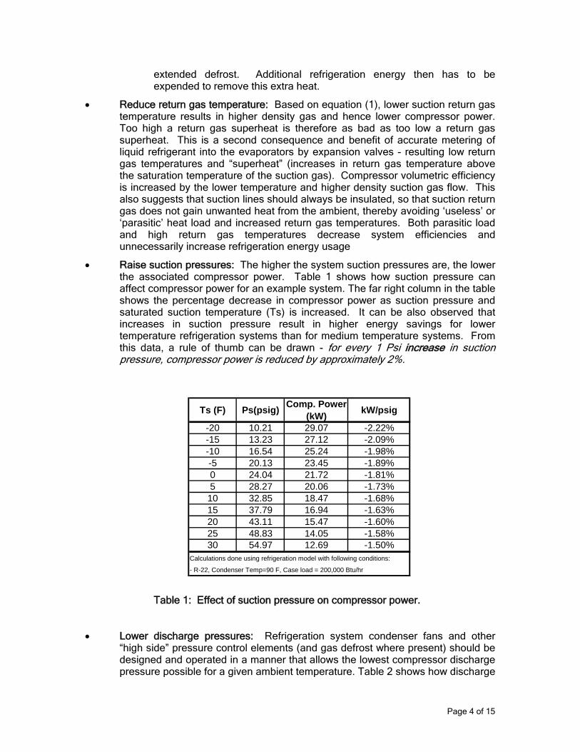
• Raise suction pressures: The higher the system suction pressures are, the lower the associated compressor power. Table 1 shows how suction pressure can affect compressor power for an example system. The far right column in the table shows the percentage decrease in compressor power as suction pressure and saturated suction temperature (Ts) is increased. It can be also observed that increases in suction pressure result in higher energy savings for lower temperature refrigeration systems than for medium temperature systems. From this data, a rule of thumb can be drawn - for every 1 Psi increase in suction pressure, compressor power is reduced by approximately 2%.
Table 1: Effect of suction pressure on compressor power.
Ts (F) Ps(psig) Comp. Power (kW) kW/psig
-20 10.21 29.07 -2.22%-15 13.23 27.12 -2.09%-10 16.54 25.24 -1.98%-5 20.13 23.45 -1.89%0 24.04 21.72 -1.81%5 28.27 20.06 -1.73%10 32.85 18.47 -1.68%15 37.79 16.94 -1.63%20 43.11 15.47 -1.60%25 48.83 14.05 -1.58%30 54.97 12.69 -1.50%
Calculations done using refrigeration model with following conditions:
- R-22, Condenser Temp=90 F, Case load = 200,000 Btu/hr
• Lower discharge pressures: Refrigeration system condenser fans and other “high side” pressure control elements (and gas defrost where present) should be designed and operated in a manner that allows the lowest compressor discharge pressure possible for a given ambient temperature. Table 2 shows how discharge
Page 4 of 15
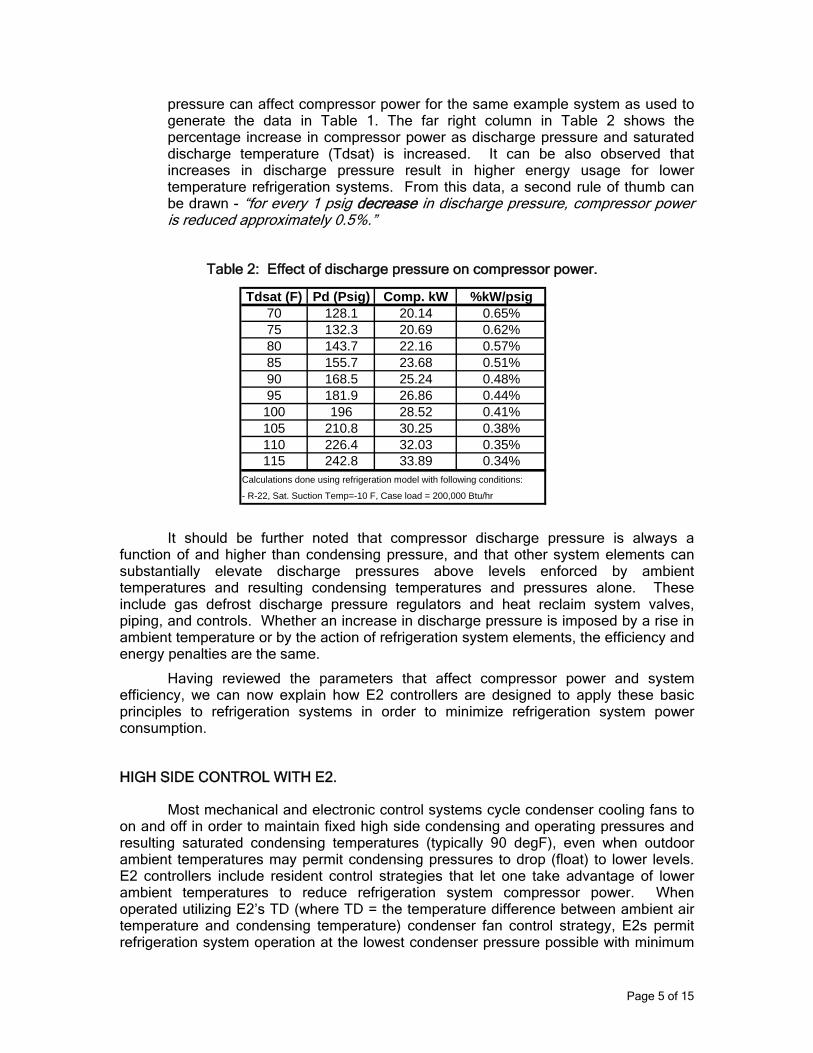
pressure can affect compressor power for the same example system as used to generate the data in Table 1. The far right column in Table 2 shows the percentage increase in compressor power as discharge pressure and saturated discharge temperature (Tdsat) is increased. It can be also observed that increases in discharge pressure result in higher energy usage for lower temperature refrigeration systems. From this data, a second rule of thumb can be drawn - “for every 1 psig decrease in discharge pressure, compressor power is reduced approximately 0.5%.”
Table 2: Effect of discharge pressure on compressor power.
It should be further noted that compressor discharge pressure is always a function of and higher than condensing pressure, and that other system elements can substantially elevate discharge pressures above levels enforced by ambient temperatures and resulting condensing temperatures and pressures alone. These include gas defrost discharge pressure regulators and heat reclaim system valves, piping, and controls. Whether an increase in discharge pressure is imposed by a rise in ambient temperature or by the action of refrigeration system elements, the efficiency and energy penalties are the same.
Having reviewed the parameters that affect compressor power and system efficiency, we can now explain how E2 controllers are designed to apply these basic principles to refrigeration systems in order to minimize refrigeration system power consumption.
Tdsat (F) Pd (Psig) Comp. kW %kW/psig70 128.1 20.14 0.65%75 132.3 20.69 0.62%80 143.7 22.16 0.57%85 155.7 23.68 0.51%90 168.5 25.24 0.48%95 181.9 26.86 0.44%100 196 28.52 0.41%105 210.8 30.25 0.38%110 226.4 32.03 0.35%115 242.8 33.89 0.34%
Calculations done using refrigeration model with following conditions:
- R-22, Sat. Suction Temp=-10 F, Case load = 200,000 Btu/hr
HIGH SIDE CONTROL WITH E2.
Most mechanical and electronic control systems cycle condenser cooling fans to on and off in order to maintain fixed high side condensing and operating pressures and resulting saturated condensing temperatures (typically 90 degF), even when outdoor ambient temperatures may permit condensing pressures to drop (float) to lower levels. E2 controllers include resident control strategies that let one take advantage of lower ambient temperatures to reduce refrigeration system compressor power. When operated utilizing E2’s TD (where TD = the temperature difference between ambient air temperature and condensing temperature) condenser fan control strategy, E2s permit refrigeration system operation at the lowest condenser pressure possible with minimum
Page 5 of 15
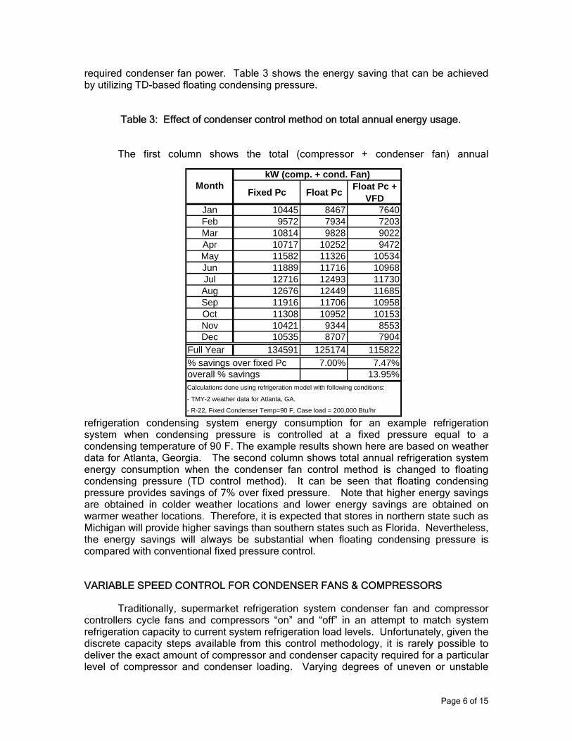
required condenser fan power. Table 3 shows the energy saving that can be achieved by utilizing TD-based floating condensing pressure.
Table 3: Effect of condenser control method on total annual energy usage.
The first column shows the total (compressor + condenser fan) annual
refrigeration condensing system energy consumption for an example refrigeration system when condensing pressure is controlled at a fixed pressure equal to a condensing temperature of 90 F. The example results shown here are based on weather data for Atlanta, Georgia. The second column shows total annual refrigeration system energy consumption when the condenser fan control method is changed to floating condensing pressure (TD control method). It can be seen that floating condensing pressure provides savings of 7% over fixed pressure. Note that higher energy savings are obtained in colder weather locations and lower energy savings are obtained on warmer weather locations. Therefore, it is expected that stores in northern state such as Michigan will provide higher savings than southern states such as Florida. Nevertheless, the energy savings will always be substantial when floating condensing pressure is compared with conventional fixed pressure control.
Fixed Pc Float Pc Float Pc + VFD
Jan 10445 8467 7640Feb 9572 7934 7203Mar 10814 9828 9022Apr 10717 10252 9472May 11582 11326 10534Jun 11889 11716 10968Jul 12716 12493 11730Aug 12676 12449 11685Sep 11916 11706 10958Oct 11308 10952 10153Nov 10421 9344 8553Dec 10535 8707 7904
Full Year 134591 125174 115822% savings over fixed Pc 7.00% 7.47%overall % savings 13.95%Calculations done using refrigeration model with following conditions:
- TMY-2 weather data for Atlanta, GA.
- R-22, Fixed Condenser Temp=90 F, Case load = 200,000 Btu/hr
kW (comp. + cond. Fan)Month
VARIABLE SPEED CONTROL FOR CONDENSER FANS & COMPRESSORS
Traditionally, supermarket refrigeration system condenser fan and compressor controllers cycle fans and compressors “on” and “off” in an attempt to match system refrigeration capacity to current system refrigeration load levels. Unfortunately, given the discrete capacity steps available from this control methodology, it is rarely possible to deliver the exact amount of compressor and condenser capacity required for a particular level of compressor and condenser loading. Varying degrees of uneven or unstable
Page 6 of 15
system operation often result, along higher energy consumption due to control overshoot of desired suction and condensing pressures, and sometimes destructive rapid start and stop cycling of fan and compressor motors. The application of variable speed drives (VSDs) to condenser fans and compressors motors, controlled using proprietary E2 VSD algorithms, can eliminate these capacity matching problems, and save additional energy as well. The fourth column in Table 3 shows energy consumption when variable frequency drives (VFDs) are used to modulate condenser fan speeds together with both floating condensing pressure and TD control algorithms. It can be seen that when varying the speed of condenser fans is used as the fan capacity control method, an additional 7.47% saving can be achieved on top of what is achieved using floating pressure and TD control. Therefore, an overall 13.95% energy saving can be achieved when variable speed along with floating condensing pressure control strategies are employed. For condenser fans, almost all of the savings from utilization of VSD control are due to the affinity laws for fans (which tell us fan motor power varies with the cube of fan speed while fan air volume varies linearly with speed) and improved utilization of condenser surface.
VSDs can also be applied to refrigeration compressors as well using proprietary E2 VSD compressor control algorithms. Savings in this case flow primarily from improved suction pressure control and therefore slightly higher on average suction pressures, as well as from modest but still significant compressor volumetric efficiency increases at lower speeds. Analysis of savings from application of VSDs for compressor capacity control can be complex, but savings on the order of 7 to 12% can be anticipated, depending on locale and refrigeration system configuration.
SUCTION PRESSURE FLOAT WITH ELECTRONIC PRESSURE REGULATOR
Conventional refrigeration systems use mechanical evaporator (suction) pressure regulators (EPRs) and fixed setpoint compressor suction pressure controllers, either mechanical or electronic, to control fixture temperature and compressor operation. Refrigeration service technicians set EPRs to achieve desired evaporator and therefore fixture temperatures. Compressor suction pressure controls are then normally set several pounds below the EPR settings. Figure 2 shows a schematic of this common refrigeration system control methodology. The system EPR valve has been adjusted to provide the required fixture temperature, in this case 25 degF. To achieve a 25-degF-air temperature in a fixture with a 10-degF-coil temperature differential (typical for commercial refrigerated cases and storage boxes), the required evaporator coil temperature would be 15 degF. For R-404a the corresponding evaporator coil pressure is 50-psig. Assuming there is a 5 psig suction line pressure drop, then the EPR if located at the compressor is adjusted to maintain a suction line pressure of 45 psig. The compressor pressure control is then normally set at least 2 psig lower, to 43 psig, to compensate for a 2 psig pressure drop across the EPR valve (again typical) and to assure a steady pressure at the fixture evaporator.
Page 7 of 15
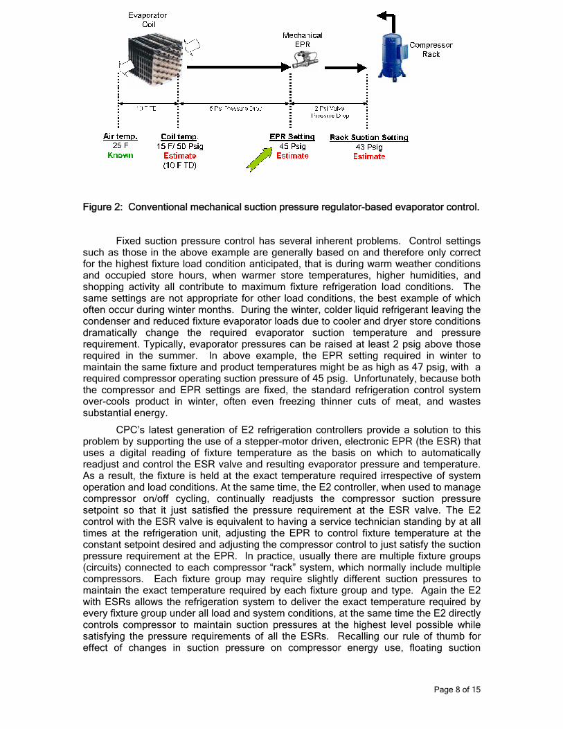
Figure 2: Conventional mechanical suction pressure regulator-based evaporator control.
Fixed suction pressure control has several inherent problems. Control settings such as those in the above example are generally based on and therefore only correct for the highest fixture load condition anticipated, that is during warm weather conditions and occupied store hours, when warmer store temperatures, higher humidities, and shopping activity all contribute to maximum fixture refrigeration load conditions. The same settings are not appropriate for other load conditions, the best example of which often occur during winter months. During the winter, colder liquid refrigerant leaving the condenser and reduced fixture evaporator loads due to cooler and dryer store conditions dramatically change the required evaporator suction temperature and pressure requirement. Typically, evaporator pressures can be raised at least 2 psig above those required in the summer. In above example, the EPR setting required in winter to maintain the same fixture and product temperatures might be as high as 47 psig, with a required compressor operating suction pressure of 45 psig. Unfortunately, because both the compressor and EPR settings are fixed, the standard refrigeration control system over-cools product in winter, often even freezing thinner cuts of meat, and wastes substantial energy.
CPC’s latest generation of E2 refrigeration controllers provide a solution to this problem by supporting the use of a stepper-motor driven, electronic EPR (the ESR) that uses a digital reading of fixture temperature as the basis on which to automatically readjust and control the ESR valve and resulting evaporator pressure and temperature. As a result, the fixture is held at the exact temperature required irrespective of system operation and load conditions. At the same time, the E2 controller, when used to manage compressor on/off cycling, continually readjusts the compressor suction pressure setpoint so that it just satisfied the pressure requirement at the ESR valve. The E2 control with the ESR valve is equivalent to having a service technician standing by at all times at the refrigeration unit, adjusting the EPR to control fixture temperature at the constant setpoint desired and adjusting the compressor control to just satisfy the suction pressure requirement at the EPR. In practice, usually there are multiple fixture groups (circuits) connected to each compressor “rack” system, which normally include multiple compressors. Each fixture group may require slightly different suction pressures to maintain the exact temperature required by each fixture group and type. Again the E2 with ESRs allows the refrigeration system to deliver the exact temperature required by every fixture group under all load and system conditions, at the same time the E2 directly controls compressor to maintain suction pressures at the highest level possible while satisfying the pressure requirements of all the ESRs. Recalling our rule of thumb for effect of changes in suction pressure on compressor energy use, floating suction
Page 8 of 15
pressure control with E2 controllers can often provide savings of 4% or more during periods of cooler weather, and substantial savings in general any time of the day, week, month or year when either the fixture heat load or compressor system capacity vary for any reason. These savings are as compared to a carefully setup and properly working traditional EPR control-based refrigeration system, the exception rather than the rule in the supermarket industry. Savings can be much greater when compared to real world EPR-based systems and conditions.
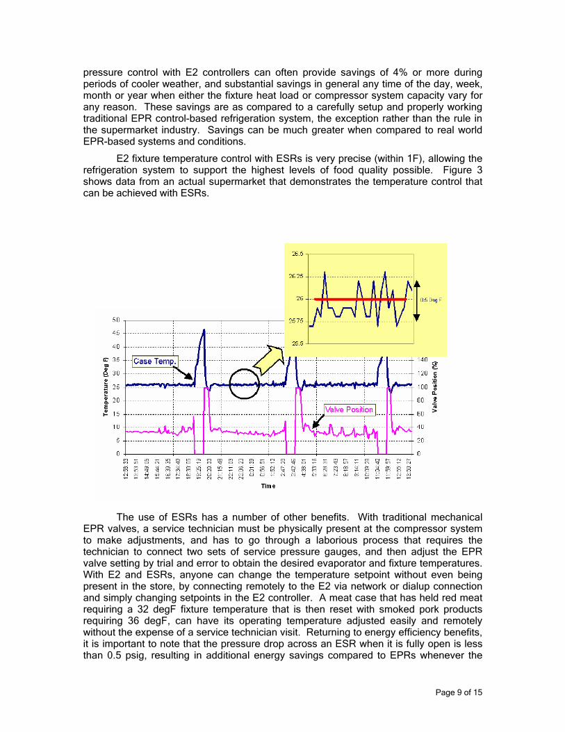
E2 fixture temperature control with ESRs is very precise (within 1F), allowing the refrigeration system to support the highest levels of food quality possible. Figure 3 shows data from an actual supermarket that demonstrates the temperature control that can be achieved with ESRs.
Figure 3. Temperature Control with Evaporator Stepper Regulator.
The use of ESRs has a number of other benefits. With traditional mechanical EPR valves, a service technician must be physically present at the compressor system to make adjustments, and has to go through a laborious process that requires the technician to connect two sets of service pressure gauges, and then adjust the EPR valve setting by trial and error to obtain the desired evaporator and fixture temperatures. With E2 and ESRs, anyone can change the temperature setpoint without even being present in the store, by connecting remotely to the E2 via network or dialup connection and simply changing setpoints in the E2 controller. A meat case that has held red meat requiring a 32 degF fixture temperature that is then reset with smoked pork products requiring 36 degF, can have its operating temperature adjusted easily and remotely without the expense of a service technician visit. Returning to energy efficiency benefits, it is important to note that the pressure drop across an ESR when it is fully open is less than 0.5 psig, resulting in additional energy savings compared to EPRs whenever the
Page 9 of 15
ESR is in this state and the suction pressure of compressor(s) serving it can be floated further upward.
In summary, E2 floating suction pressure control coupled with ESR fixture temperature control provides the following benefits over conventional EPR control:
• Energy savings of up to 8.0% due to higher compressor suction pressures possible.
• Automatic temperature adjustment to accommodate all seasonal and other system and load effects.
• Remote temperature set point changes.
• Tight fixture temperature control and reduced product shrinkage, increased shelf life and shorter required defrost duration.
• Knowledge of valve position in addition to case temperature reading provides another useful source of data for diagnosing problems on site or remotely.
EVAPORATOR CONTROL WITH ELECTRONIC EXPANSION VALVE
As mentioned near the start of this article, higher compressor suction pressures and lower suction return gas temperatures lower compressor power and refrigeration system energy usage. Therefore, it is important that the expansion valves that control the flow of refrigerant into fixture evaporator coils do so in a manner that results in the lowest gas superheat at the exit of evaporator coil possible, without allowing liquid refrigerant to pass from the coil in the suction line and possibly flood and damage the compressors. Inadequate refrigerant flow into an evaporator coil, as evidenced by high coil exit suction superheat temperatures, reduces evaporator coil heat transfer effectiveness and heat transfer rates, requiring as a result a larger temperature difference between the evaporator coil and the fixture air flow to remove an equal amount of heat. This means higher evaporator superheat conditions require lower EPR or ESR and compressor suction pressure settings to achieve the same case air.
Mechanical thermal expansion valves (TXVs) are typically used to meter refrigerant into evaporator coils and managed outlet superheat. These valves have numerous limitations. First of all, they must be set manually using a difficult process not well understood and executed by many service technicians. When setting these valves, the service technician is forced to open up the refrigerated fixture, disturbing its normal air flow and heat transfer and making proper valve setup almost impossible. Once the TXV is initially adjusted, any change in refrigeration system conditions including liquid pressure or sub-cooling, evaporator suction pressure, case load and case airflow will result in the valve no longer being properly set and superheats that are either too high or too low. During cold weather, lower liquid refrigerant temperatures at TXVs cause liquid refrigerant to flood through evaporator coils. An experimental study has shown that the flooding can be as high as 5 lbs/hr per display case. With 100 cases in a typical supermarket, the total extra load on the refrigeration compressors can be as high as 500 lb/hr, which results in approximately 5 kW of additional compressor power. This results in a 10-15% parasitic energy loss. During warmer periods when condensing and liquid temperatures rise, conventional TXVs can starve refrigerated case evaporators, which
Page 10 of 15
forces lower suction pressures to maintain fixture temperatures and hence higher compressor energy consumption.
Also, since mechanical TXVs require a substantial pressure drop across them (from 60 to 100 psig typically) to function properly, floating refrigeration condensing pressure to take advantage of cooler outdoor conditions may not be possible, as available TXV liquid pressure differential declines with dropping condensing pressures. The E2 family of controllers includes case (refrigerated display fixture) controllers (CC-100, EC-2, EC-3) that utilize an electronic expansion valve (EEV) in place of the mechanical TXV and control the superheat at the exit of evaporator coils accurately under all system conditions and fixture loads. Unlike mechanical TXVs, where the operation of the TXV is dependent on suction and liquid pressures as well as springs and capillary tubes for valve operation, the EEV requires little more than the sophisticated software algorithms within the valve controller to provide precise evaporator outlet superheat control under all conditions.
OPTIMUM DEFROST CONTROL
A conventional refrigeration control system defrosts the evaporator coil at a fixed time each day for a fixed duration. For example, a lineup of meat cases may be defrosted three times a day for 40 minutes. However, on a low humidity days (typically in winter), the evaporator coils do not accumulate as much frost and hence the coils do not require the same defrost duration as during high humidity days. E2 controllers incorporate a defrost algorithm that is designed to overcome this limitation. The algorithm accepts an additional defrost termination input parameter, either fixture evaporator coil or discharge air temperature, with which to terminate defrost, based on a temperature termination setpoint value. In this fashion the E2 automatically adjusts the duration of defrost based on the amount of frost in the coil. The defrost time required on the low humidity days can be less than half of that required in high humidity days. This saves not only the electrical energy expended on electric or gas defrost but also the extra defrost heat load the refrigeration system has to remove from the display case after defrost.
ANTI-CONDENSATE HEATER CONTROL
Moisture in the air inside a supermarket will condense on the cold surface of frozen food reachin case glass doors unless heat is applied to the doors. Because of this, almost all reachin case glass doors have heaters on and around the glass door running 100% of the time to keep the glass temperature well above the dew point temperature. However, the humidity of the store is not same throughout the day, week, month and year. During periods of low inside humidity, less heat is required to keep the doors clear from condensation than at high humidity conditions. E2 controllers are equipped with a control algorithm that permits heater power to be cycled from 0% to 100% depending on the store dew point. For example, if dew point in a supermarket ranges from 30-60 degF, then the algorithm can be programmed to cycle heaters on from 20% and 100% on time, rather than on 100% of the time.
Figure 4 below shows the outside dew point temperature for Atlanta, Georgia. As can be seen, the dew point temperature varies throughout the year. Conventional control keeps the anti-condensate heater 100% on all the time, whereas, control via the E2 controller can cycle the heater depending on the dew-point temperatures in the store.
Page 11 of 15
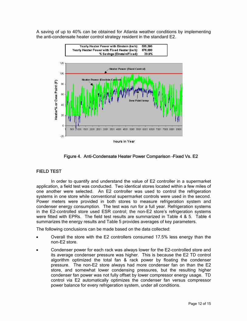
A saving of up to 40% can be obtained for Atlanta weather conditions by implementing the anti-condensate heater control strategy resident in the standard E2.
Figure 4. Anti-Condensate Heater Power Comparison –Fixed Vs. E2
FIELD TEST
In order to quantify and understand the value of E2 controller in a supermarket application, a field test was conducted. Two identical stores located within a few miles of one another were selected. An E2 controller was used to control the refrigeration systems in one store while conventional supermarket controls were used in the second. Power meters were provided in both stores to measure refrigeration system and condenser energy consumption. The test was run for a full year. Refrigeration systems in the E2-controlled store used ESR control; the non-E2 store’s refrigeration systems were fitted with EPRs. The field test results are summarized in Table 4 & 5. Table 4 summarizes the energy results and Table 5 provides averages of key parameters.
The following conclusions can be made based on the data collected:
• Overall the store with the E2 controllers consumed 17.5% less energy than the non-E2 store.
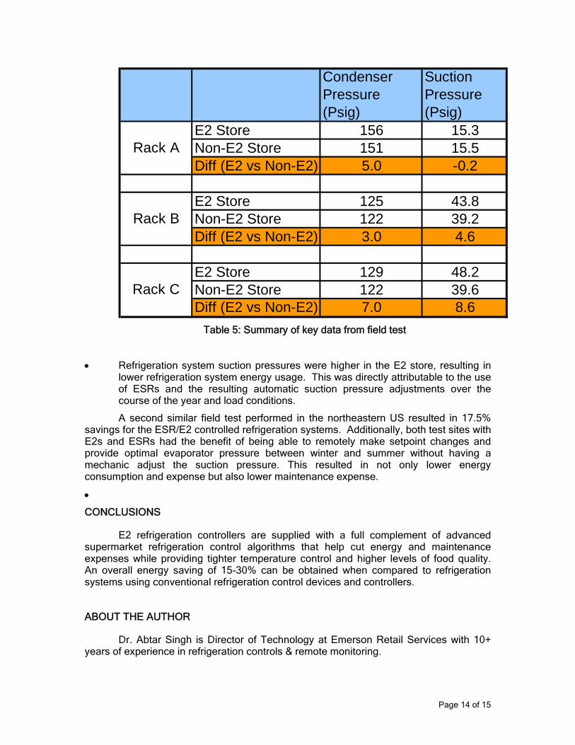
• Condenser power for each rack was always lower for the E2-controlled store and its average condenser pressure was higher. This is because the E2 TD control algorithm optimized the total fan & rack power by floating the condenser pressure. The non-E2 store always had more condenser fan on than the E2 store, and somewhat lower condensing pressures, but the resulting higher condenser fan power was not fully offset by lower compressor energy usage. TD control via E2 automatically optimizes the condenser fan versus compressor power balance for every refrigeration system, under all conditions.
Page 12 of 15
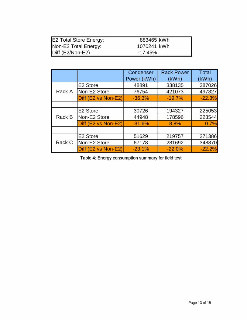
E2 Total Store Energy: 883465 kWhNon-E2 Total Energy: 1070241 kWhDiff (E2/Non-E2) -17.45%
Condenser Power (kWh)
Rack Power (kWh)
Total (kWh)
E2 Store 48891 338135 387026Non-E2 Store 76754 421073 497827Diff (E2 vs Non-E2) -36.3% -19.7% -22.3%
E2 Store 30726 194327 225053Non-E2 Store 44948 178596 223544Diff (E2 vs Non-E2) -31.6% 8.8% 0.7%
E2 Store 51629 219757 271386Non-E2 Store 67178 281692 348870Diff (E2 vs Non-E2) -23.1% -22.0% -22.2%
Rack A
Rack B
Rack C
Table 4: Energy consumption summary for field test
Page 13 of 15
CondenserPressure (Psig)
SuctionPressure (Psig)
E2 Store 156 15.3Non-E2 Store 151 15.5Diff (E2 vs Non-E2) 5.0 -0.2
E2 Store 125 43.8Non-E2 Store 122 39.2Diff (E2 vs Non-E2) 3.0 4.6
E2 Store 129 48.2Non-E2 Store 122 39.6Diff (E2 vs Non-E2) 7.0 8.6
Rack A
Rack B
Rack C
Table 5: Summary of key data from field test
• Refrigeration system suction pressures were higher in the E2 store, resulting in lower refrigeration system energy usage. This was directly attributable to the use of ESRs and the resulting automatic suction pressure adjustments over the course of the year and load conditions.
A second similar field test performed in the northeastern US resulted in 17.5% savings for the ESR/E2 controlled refrigeration systems. Additionally, both test sites with E2s and ESRs had the benefit of being able to remotely make setpoint changes and provide optimal evaporator pressure between winter and summer without having a mechanic adjust the suction pressure. This resulted in not only lower energy consumption and expense but also lower maintenance expense.
•
CONCLUSIONS
E2 refrigeration controllers are supplied with a full complement of advanced supermarket refrigeration control algorithms that help cut energy and maintenance expenses while providing tighter temperature control and higher levels of food quality. An overall energy saving of 15-30% can be obtained when compared to refrigeration systems using conventional refrigeration control devices and controllers.
ABOUT THE AUTHOR
Dr. Abtar Singh is Director of Technology at Emerson Retail Services with 10+ years of experience in refrigeration controls & remote monitoring.
Page 14 of 15
REFERENCES
ASHRAE Handbook (Fundamentals), ASHRAE, 1791 Tullie Circle, N.E., Atlanta, GA 30329. 1993.
CPC Peripherals Installation and Operation, 026-1701 Rev 0 01-05-98, Computer Process Controls Inc., 1640, Airport Rd. Suite 105, Kennesaw, GA, 1998.
E2 RX Refrigeration Controller Installation and Operation Manual, 026-1610 Rev 1 5-05-03, Computer Process Controls Inc., 1640, Airport Rd. Suite 105, Kennesaw, GA, 2001.
Pulse Modulating Anti-Sweat Control (PMAC II) and PMAC Solo Installation and Operation Manual, 026-1501 Rev 5 3-20-03, Computer Process Controls Inc., 1640, Airport Rd. Suite 105, Kennesaw, GA, 2000.
Moran, M.J., and Shapiro, H.N. Fundamentals of Engineering Thermodynamics, 4th Ed., John Wiley & Sons, Inc. New York, 1999.
Ultrasite 32 User’s Guide, 026-1002 Rev 3 9-28-99, Computer Process Controls Inc., 1640, Airport Rd. Suite 105, Kennesaw, GA, 1999.
Page 15 of 15