Embed Size (px)
Citation preview

Optimum Pool
In order for your pool warranty to be deemed valid you must register your pool at
www. 1mypoolwarranty.com

POOL SAFETY
PLEASE READ PRIOR TO INSTALLATION
Section 1 Section 2
1
Failure to observe these warnings may result in permanent injury, paralysis from a broken neck, and death due to electrocution
or drowning. This pool is NOT designed for diving or jumping. Serious injuries can result from jumping or diving into shallow
water! Carefully read, understand and follow all information in this user manual before installing and enjoying your swimming
pool. These warnings, instructions and safety guidelines address common risks of water recreation, but they cannot cover all
possible risks and dangers in all cases. Always use caution and employ common sense and good judgment when enjoying any
water activity.
WARNING!
Your pool contains a large quantity of water, and any amount of water, even shallow water, can present serious dangers to life and health unless these safety rules are strictly
observed. First-time users run the highest risk of injury. Ensure all bathers understand these safety rules, and encourage all bathers, especially children, to learn how to swim.
Learn basic life support (CPR) and refresh this knowledge regularly. Instruct all bathers, including children, what to do in case of emergency. Keep a working phone and a list of
emergency phone numbers near the pool. This can save a life. To ensure your pool is used safely, you MUST observe and enforce the following safety precautions:
1. NO JUMPING OR DIVINGThe top rail of your pool is not a walkway and must not be used for jumping or diving. Do not permit jumping
or diving into the pool from a pool deck, the top rail of the pool, or from any structure outside the pool.
Diving or jumping into the pool can result in serious injury.
2. NEVER USE THE POOL ALONENever permit the pool to be used unless it is attended by at least one person other than the bather.
Someone should always be available to lend assistance in an emergency. Designate a competent adult to
supervise the pool when in use. Vigilant supervision of weak swimmers and non-swimmers by a competent
adult is required at all times. Children under five are at the highest risk of drowning.
3. NEVER LEAVE CHILDREN UNATTENDEDNever leave a child alone and unsupervised in or near the pool — not even for a second. There is no
substitute for constant adult supervision.
4. NO ROUGH PLAYDo not permit rough playing or roughhousing in and around your pool. Surfaces can become slippery and
hazardous when wet.
5. LIGHT THE POOL AT NIGHTIf the pool is used after dusk, adequate lighting must be provided. Illumination in the pool area must be
sufficient to allow swimmers to clearly judge pool depth and all features in and around the pool. For lighting
recommendations, consult your local licensed electrical contractor.
6. RESTRICT ACCESS TO THE POOLDo not leave chairs or other furniture beside the pool that could be used by a child to access the pool.
Ladders must be removed whenever the pool is unattended. A fence with a lockable gate around the pool
or yard is strongly recommended and may be required by law in some areas. Secure doors and windows,
where applicable, to prevent unauthorized access to the swimming pool. Remove all toys from the
swimming pool and surrounding area when not in use to avoid attracting children to the pool. Barriers, pool
covers, pool alarms or similar safety devices are helpful aids, but they are not substitutes for continuous
adult supervision.
7. NO ALCOHOL OR DRUGSNever drink alcoholic beverages or use any intoxicants which could hinder your judgment and reflexes in an
emergency.
8. KEEP YOUR POOL CLEAN AND SANITARYYour filter system will remove suspended particles from the water and the surface skimmer will remove
insects, leaves and other debris from the water surface. Use the correct pool chemicals as directed to
destroy harmful bacteria and prevent formation of algae. Remember, unsanitary water is a serious health
hazard.
8. KEEP OFF THE TOP LEDGESDo not walk or stand on the top ledges. They can become slippery and result in serious injury.
9. POOL COVER SAFETYThe pool cover (sold separately) must have a tamper-proof locking retainer cable that positions the
cover around the pool wall and keeps it securely in place. Never allow anyone, especially small children
on the cover. Asphyxiation or drowning could result. Be sure to remove pool cover completely from the
water surface before entering the pool. When purchasing any pool cover, please consult a pool
professional.
11. ELECTRICAL HAZARDNever touch or attempt to service electrical equipment, including the filter, when your body and/or the
ground is wet. Electrocution or permanent injury due to high voltage (120V AC) could result. The pool
should be bonded in accordance with Section 680-26 of the National Electrical Code. For further
assistance contact your dealer or a local licensed electrician. Do not use pool during electrical or rain
storms.
12. SAFETY ROPE AND POLEKeep a safety rope measuring at least 50 feet long (15.24 meters) by ¼” thick( .635cm) securely
attached to a flotation buoy with an outside diameter of 15” (38.1cm) in a prominent, easily accessible
area by your pool. Keep a pole not less that 16 feet (4,88m) long with a blunt or hook end available at
poolside in case of emergencies. Weak swimmers and non-swimmers should wear personal protection
equipment when using the pool.
13. POOL CHEMICALSStore pool chemicals out of the reach of children. Do not place chlorine, chlorine tablets or sticks
directly into skimmer, or winterize your pool with liquid chlorine. Damage to the skimmer, pool liner and
filter will result. Failure to observe this instruction will void all component warranties. Always follow
chemical manufacturer’s instructions when storing, handling and dispensing pool chemicals.
14. CHECK FOR DAMAGEPeriodically inspect your pool and ladder components for damage and wear. Be sure all screws are in
place and tightened according to manufacturer’s instructions. Replace all damaged or worn
components and tighten all screws before you use the pool, deck or ladders. At first sign of rust,
remove and touch up immediately.
15. POOL PARTSNever modify the pool, its components or its accessories, remove hardware, or drill holes in the pool,
deck or ladder components unless instructed to do so by the manufacturer. Your pool wall is made of
thin, but strong metal, so please use work gloves to protect your hands during installation. Always
utilize original manufactured parts for replacement. Failure to do so may void your warranty.

.
.
.
.
.
The safety stickers must be installed as per the following
instructions. Failure to properly install warning labels will void
warranty. Failure to mount these safety labels may subject you to
substantial liability in case of injury. These warnings are not to be
removed under any circumstances. If they become discolored or
fall off, please request replacements from the manufacturer,
which will be provided free of charge.
.
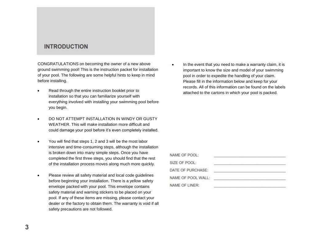
CONGRATULATIONS on becoming the owner of a new above
ground swimming pool! This is the instruction packet for installation
of your pool. The following are some helpful hints to keep in mind
before installing.
Read through the entire instruction booklet prior to
installation so that you can familiarize yourself with
everything involved with installing your swimming pool before
you begin.
DO NOT ATTEMPT INSTALLATION IN WINDY OR GUSTY
WEATHER. This will make installation more difficult and
could damage your pool before it’s even completely installed.
You will find that steps 1, 2 and 3 will be the most labor
intensive and time-consuming steps, although the installation
is broken down into many simple steps. Once you have
completed the first three steps, you should find that the rest
of the installation process moves along much more quickly.
Please review all safety material and local code guidelines
before beginning your installation. There is a yellow safety
envelope packed with your pool. This envelope contains
safety material and warning stickers to be placed on your
pool. If any of these items are missing, please contact your
dealer or the factory to obtain them. The warranty is void if all
safety precautions are not followed.
In the event that you need to make a warranty claim, it is
important to know the size and model of your swimming
pool in order to expedite the handling of your claim.
Please fill in the information below and keep for your
records. All of this information can be found on the labels
attached to the cartons in which your pool is packed.
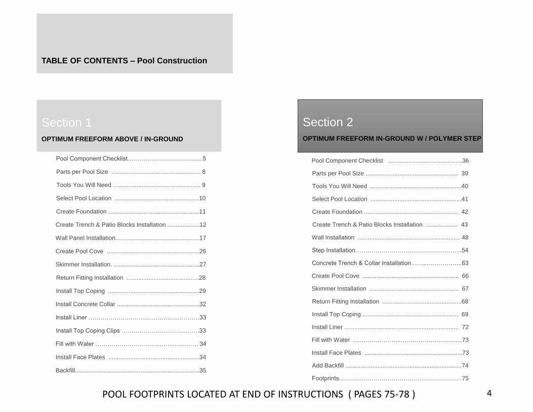
TABLE OF CONTENTS – Pool Construction
Pool Component Checklist…………………………….....5
Parts per Pool Size ..................................................... 8
Tools You Will Need .................................................... 9
Select Pool Location ..................................................10
Create Foundation ......................................................11
Create Trench & Patio Blocks Installation ...................12
Wall Panel Installation..................................................17
Create Pool Cove .......................................................26
Skimmer Installation. ...................................................27
Return Fitting Installation ...........................................28
Install Top Coping ......................................................29
Install Concrete Collar .................................................32
Install Liner ………………………...….…….......……….33
Install Top Coping Clips …………………………..…….33
Fill with Water …………………………..……..…..……. 34
Install Face Plates ......................................................34
Backfill..........................................................................35
Section 1 Section 2
OPTIMUM FREEFORM ABOVE / IN-GROUND
Pool Component Checklist ............................................36
Parts per Pool Size ....................................................... 39
Tools You Will Need ......................................................40
Select Pool Location ......................................................41
Create Foundation ........................................................ 42
Create Trench & Patio Blocks Installation ................... 43
Wall Installation ............................................................. 48
Step Installation……………………………………………..54
Concrete Trench & Collar Installation……...……………..63
Create Pool Cove ......................................................... 66
Skimmer Installation ..................................................... 67
Return Fitting Installation ...............................................68
Install Top Coping ......................................................... 69
Install Liner .................................................................... 72
Fill with Water …………………...….……………..….……73
Install Face Plates ..........................................................73
Add Backfill .....................................................................74
Footprints…………………………………………………….75
4
OPTIMUM FREEFORM IN-GROUND W / POLYMER STEP
POOL FOOTPRINTS LOCATED AT END OF INSTRUCTIONS ( PAGES 75-78 )
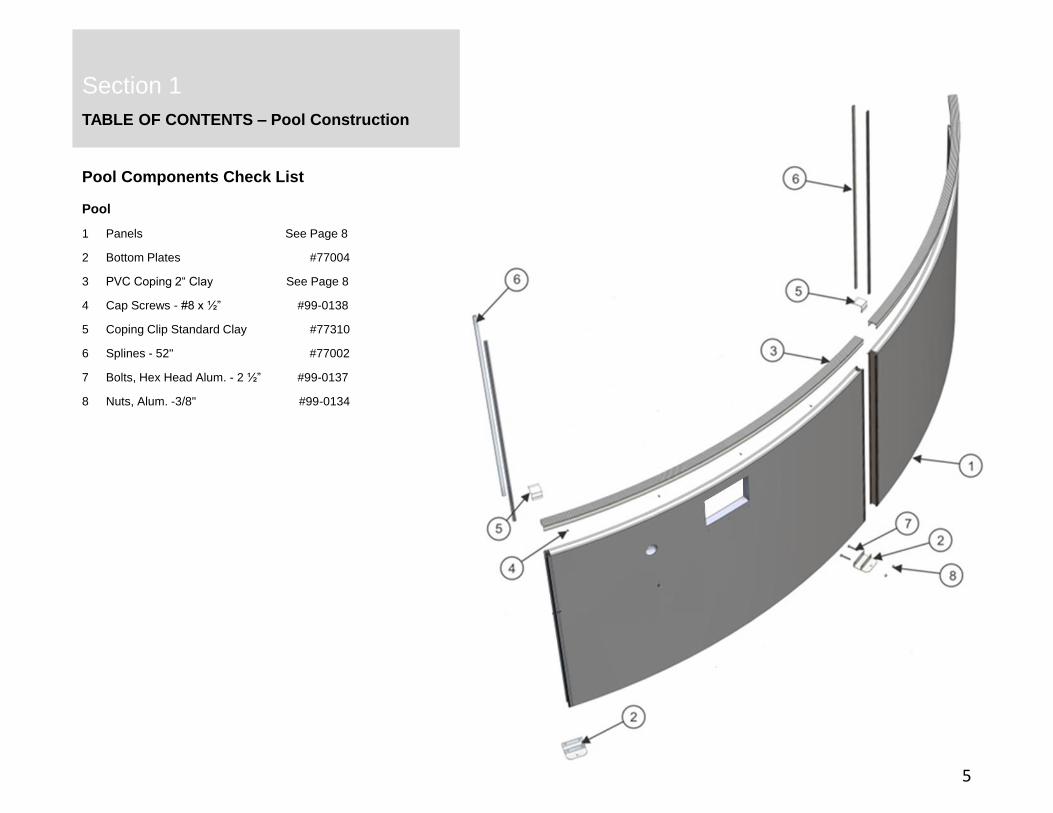
TABLE OF CONTENTS – Pool Construction
Pool
1 Panels See Page 8
2 Bottom Plates #77004
3 PVC Coping 2“ Clay See Page 8
4 Cap Screws - #8 x ½” #99-0138
5 Coping Clip Standard Clay #77310
6 Splines - 52" #77002
7 Bolts, Hex Head Alum. - 2 ½” #99-0137
8 Nuts, Alum. -3/8" #99-0134
Section 1
Section 2
Pool Components Check List
5
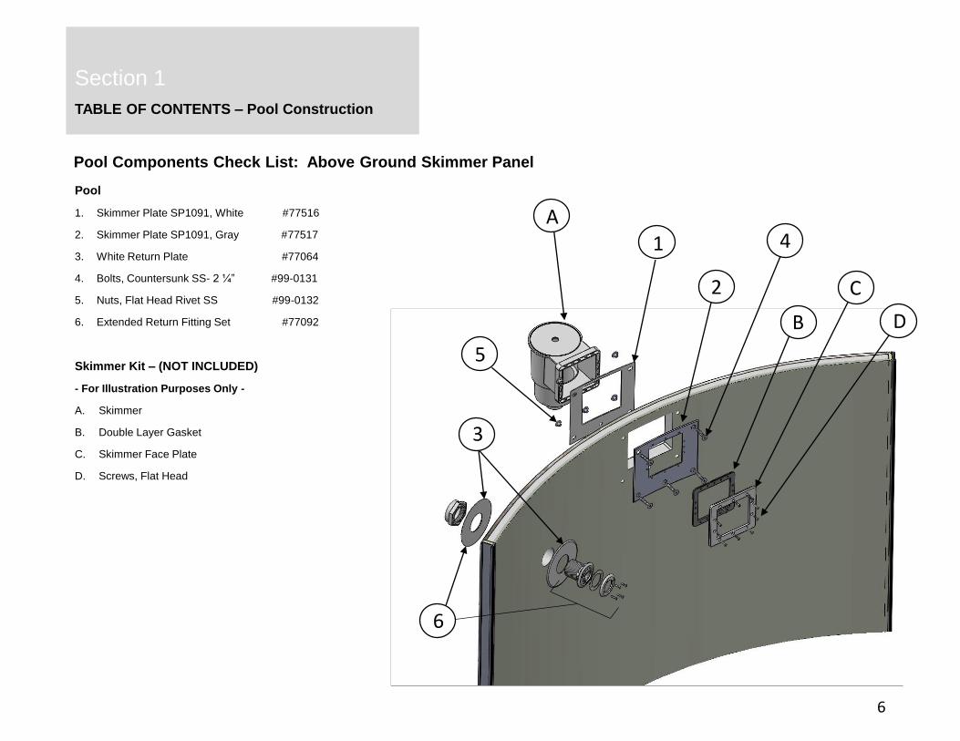
TABLE OF CONTENTS – Pool Construction
Pool
1. Skimmer Plate SP1091, White #77516
2. Skimmer Plate SP1091, Gray #77517
3. White Return Plate #77064
4. Bolts, Countersunk SS- 2 ¼” #99-0131
5. Nuts, Flat Head Rivet SS #99-0132
6. Extended Return Fitting Set #77092
Skimmer Kit – (NOT INCLUDED)
- For Illustration Purposes Only -
A. Skimmer
B. Double Layer Gasket
C. Skimmer Face Plate
D. Screws, Flat Head
Section 1
Pool Components Check List: Above Ground Skimmer Panel
6
1
2
3
4
5
6
A
B
C
D
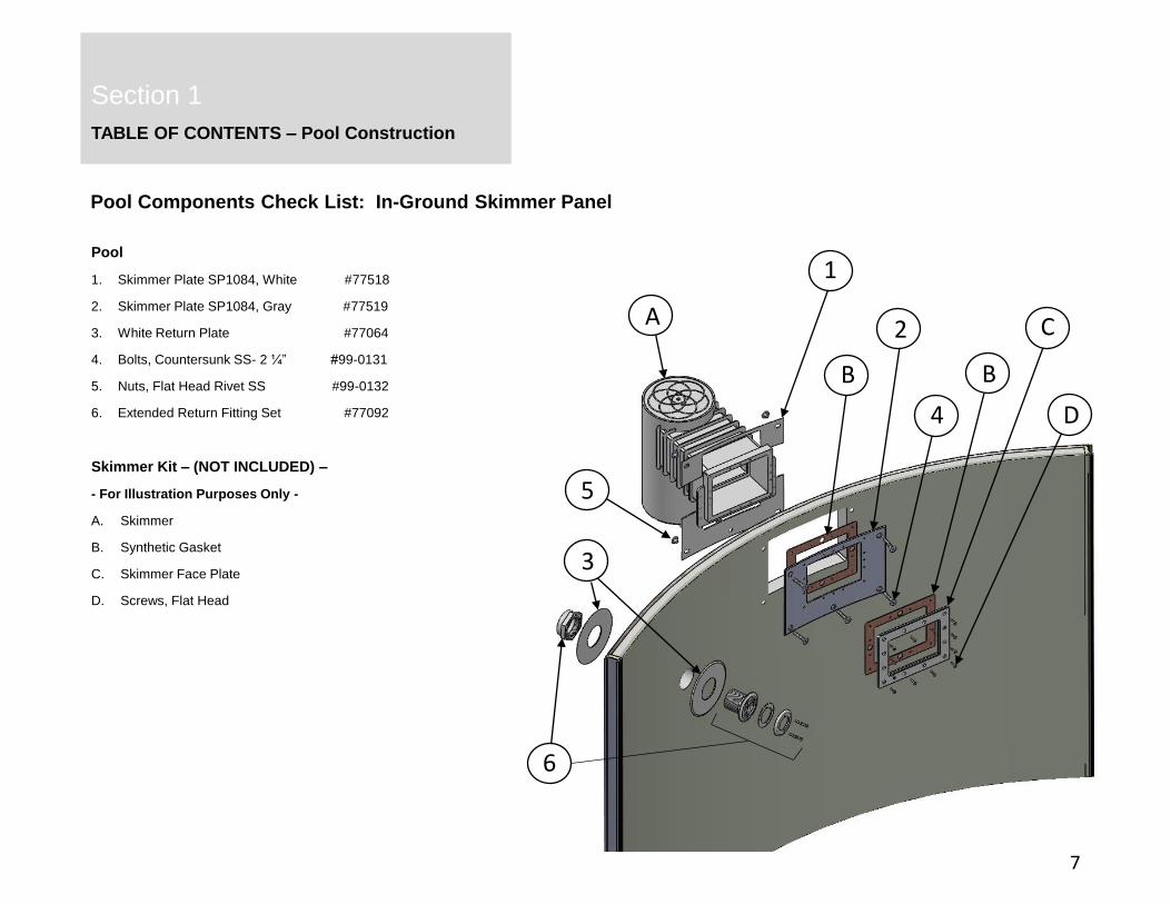
TABLE OF CONTENTS – Pool Construction
Section 1
Pool Components Check List: In-Ground Skimmer Panel
7
Pool
1. Skimmer Plate SP1084, White #77518
2. Skimmer Plate SP1084, Gray #77519
3. White Return Plate #77064
4. Bolts, Countersunk SS- 2 ¼” #99-0131
5. Nuts, Flat Head Rivet SS #99-0132
6. Extended Return Fitting Set #77092
Skimmer Kit – (NOT INCLUDED) –
- For Illustration Purposes Only -
A. Skimmer
B. Synthetic Gasket
C. Skimmer Face Plate
D. Screws, Flat Head
D
C
B
A
6
5
4
3
2
1
B

OPTIMUM FREEFORM ABOVE / IN-GROUND POOL
Section 1
Section 2
Parts Per Pool Size
8
1. PANELS Part No 1423 1528 1730 1932 COMPONENTS Part No 1423 1528 1730 1932
OPTIMUM 12FT PANEL, STANDARD 72-¼" 77319 5 5 3 BOTTOM PLATE 77004 12 13 13 15
OPTIMUM 12FT PANEL, INGROUND SKIMMER 72-¼" 77320 1 1 4 CAP SCREWS - #8 X ½" 99-0138 60 75 75 75
OPTIMUM 12FT PANEL, ABOVE GROUND SKIMMER 72-¼" 77456 5 COPING CLIP STANDARD CLAY 77310 12 13 13 15
OPTIMUM 14FT PANEL, STANDARD 84-¼" 77334 5 6 SPLINE - 52" 77002 24 26 26 30
OPTIMUM 14FT PANEL, INGROUND SKIMMER 84-¼" 77335 1 7 BOLT, HEX HEAD ALUM. - 2-½" 99-0137 24 26 26 30
OPTIMUM 14FT PANEL, ABOVE GROUND SKIMMER 84-¼" 77457 8 NUT, ALUM. - 3/8" 99-0134 24 26 26 30
OPTIMUM 16FT PANEL, STANDARD 73-7/16" 77055 7 9 SLIMMER PLATE SP 1091 WHITE (OUTSIDE POOL) 775161 1 1 1
OPTIMUM 16FT PANEL, INGROUND SKIMMER 73-7/16" 77071 1 10 SKIMMER PLATE SP 1084 WHITE (OUTSIDE POOL) 77518
OPTIMUM 16FT PANEL, ABOVE GROUND SKIMMER 73-7/16" 77458 11 SKIMMER PLATE SP 1091 GRAY (INSIDE POOL) 775171 1 1 1
OPTIMUM FREEFORM PANEL - SM BUMP 57" 77378 1 12 SKIMMER PLATE SP 1084 GRAY (INSIDE POOL) 77519
OPTIMUM FREEFORM PANEL - SM REVERSE BUMP 35-¼" 77379 2 13 RETURN PLATE WHITE (INSIDE/OUTSIDE) 77064 2 2 2 2
OPTIMUM FREEFORM PANEL - SM INDENT 38-5/8" 77380 2 14 BOLT, COUNTERSUNK SS - 2" 99-0130 4 6 6 6
OPTIMUM FREEFORM PANEL - SM REVERSE INDENT 46-9/16" 77381 1 15 BOLT, COUNTERSUNK SS - 2-¼" 99-0131 17 17 17 17
OPTIMUM FREEFORM PANEL - LG REVERSE BUMP 46-9/16" 77381 2 2 2 16 NUT, FLAT HEAD RIVET SS - 3/8" 99-0132 21 23 23 23
OPTIMUM FREEFORM PANEL - LG BUMP 50" 77386 2 2 2 17 REBAR - 3/8 X 15" 77001 4 4 4 6
OPTIMUM FREEFORM PANEL - LG INDENT 64-½" 77387 2 2 2 18 EXTENDED RETURN FITTING 77092 1 1 1 1
OPTIMUM FREEFORM PANEL - LG REVERSE INDENT 56-5/16" 77388 1 1 1 19 STRAIGHT PANEL CONNECTOR 77026 8 9 9 9
TOTAL PANEL COUNT - 12 13 13 15 20 SPLINE, SHORT 5-¾" 77014 32 36 36 36
21 SPINE, EXTENDED 52" 77013 16 18 18 18
2. PVC TOP COPING Part No 1423 1528 1730 1932 22 A-FRAME UPRIGHT 77033 8 9 9 9
PVC COPING STANDARD CLAY 12FT 78-3/16" 77309 6 6 23 A-FRAME COVER 77036 8 9 9 9
PVC COPING STANDARD CLAY 14FT 90-¾" 77325 6 24 A-FRAME COVER FOAM INSERT 77069 8 9 9 9
PVC COPING STANDARD CLAY 16FT 77-1/8" 77006 8 25 SCREW, FLAT HEAD 2" LONG 99-0130 16 18 18 18
PVC COPING STANDARD CLAY SMALL BUMP 61-¾" 77340 1 26 BOLT, HEX HEAD 8" LONG 99-0141 24 27 27 27
PVC COPING STANDARD CLAY SMALL REVERSE BUMP 38-5/8" 77341 2 27 NUT, 3/8" SS 99-0142 24 27 27 27
PVC COPING STANDARD CLAY SMALL INDENT 41-½" 77342 1 28 WASHER - 7/8" ALUMINUM 99-0133 48 54 54 54
PVC COPING STANDARD CLAY SMALL REVERSE INDENT 77343 2 2 2 2 29 FREEFORM SIDE BRACE SM - 35" 77395 4
PVC COPING STANDARD CLAY LARGE REVERSE BUMP 50" 30 FREEFORM SIDE BRACE SM/LG - 46-¾" 77396 2 4 4 4
PVC COPING STANDARD CLAY LARGE BUMP 53-7/16" 77347 2 2 2 31 FREEFORM SIDE BRACE LG - 57-¼" 77397 2 2 2
PVC COPING STANDARD CLAY LARGE INDENT 67-¾" 77348 1 1 1 32 SIDE BRACE MOUNTING BRACKET - LEFT 77153 6 6 6 6
PVC COPING STANDARD CLAY LARGE REVESE INDENT 60-7/8" 77349 2 2 2 33 SIDE BRACE MOUNTING BRACKET - RIGHT 77155 6 6 6 6
OPTIMUM FREEFORM ABOVE / IN-GROUND POOL
Section 1
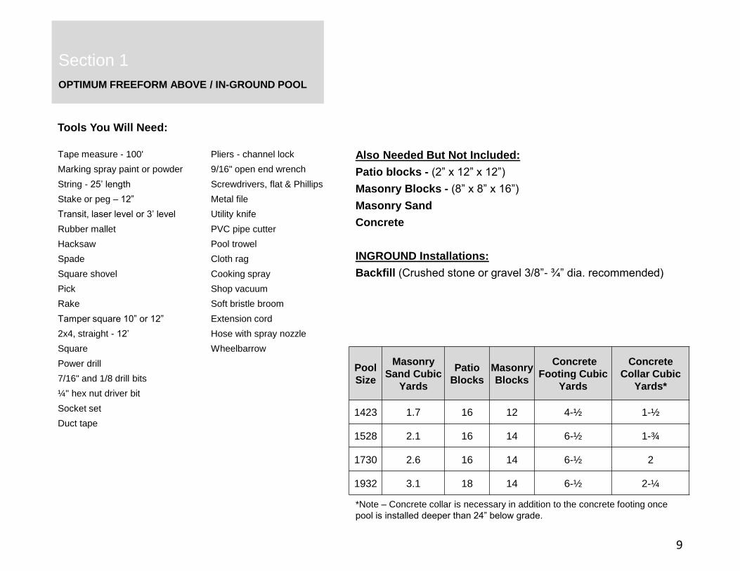
Tools You Will Need:
9
Tape measure - 100'
Marking spray paint or powder
String - 25’ length
Stake or peg – 12”
Transit, laser level or 3’ level
Rubber mallet
Hacksaw
Spade
Square shovel
Pick
Rake
Tamper square 10” or 12”
2x4, straight - 12’
Square
Power drill
7/16" and 1/8 drill bits
¼" hex nut driver bit
Socket set
Duct tape
Pliers - channel lock
9/16" open end wrench
Screwdrivers, flat & Phillips
Metal file
Utility knife
PVC pipe cutter
Pool trowel
Cloth rag
Cooking spray
Shop vacuum
Soft bristle broom
Extension cord
Hose with spray nozzle
Wheelbarrow
Also Needed But Not Included:
Patio blocks - (2” x 12” x 12”)
Masonry Blocks - (8” x 8” x 16”)
Masonry Sand
Concrete
INGROUND Installations:
Backfill (Crushed stone or gravel 3/8”- ¾” dia. recommended)
Pool
Size
Masonry
Sand Cubic
Yards
Patio
Blocks
Masonry
Blocks
Concrete
Footing Cubic
Yards
Concrete
Collar Cubic
Yards*
1423 1.7 16 12 4-½ 1-½
1528 2.1 16 14 6-½ 1-¾
1730 2.6 16 14 6-½ 2
1932 3.1 18 14 6-½ 2-¼
*Note – Concrete collar is necessary in addition to the concrete footing once
pool is installed deeper than 24” below grade.
OPTIMUM FREEFORM ABOVE / IN-GROUND POOL
Section 1
Section 2
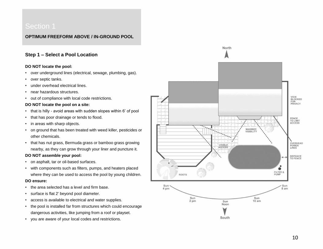
Step 1 – Select a Pool Location
10
DO NOT locate the pool:
• over underground lines (electrical, sewage, plumbing, gas).
• over septic tanks.
• under overhead electrical lines.
• near hazardous structures.
• out of compliance with local code restrictions.
DO NOT locate the pool on a site:
• that is hilly - avoid areas with sudden slopes within 6’ of pool
• that has poor drainage or tends to flood.
• in areas with sharp objects.
• on ground that has been treated with weed killer, pesticides or
other chemicals.
• that has nut grass, Bermuda grass or bamboo grass growing
nearby, as they can grow through your liner and puncture it.
DO NOT assemble your pool:
• on asphalt, tar or oil-based surfaces.
• with components such as filters, pumps, and heaters placed
where they can be used to access the pool by young children.
DO ensure:
• the area selected has a level and firm base.
• surface is flat 2' beyond pool diameter.
• access is available to electrical and water supplies.
• the pool is installed far from structures which could encourage
dangerous activities, like jumping from a roof or playset.
• you are aware of your local codes and restrictions.

OPTIMUM FREEFORM ABOVE / IN-GROUND POOL
Section 1
Section 2
Step 2 – Create a Foundation
11
2.2 Define the initial geometry by marking the pool site. The specific
dimensions for each pool size is shown on the following footprints
located on pages 13 through 16. Establish the centers of the two
semi-circles as illustrated by driving a stake into the ground at
both center points.
Attach one end of a string to one of the center stakes, measure
the string out to equal the pool radius, plus an additional 12
inches for clearance. Holding the string taut, walk the semi-circle
of the planned outer perimeter while marking the ground with
spray paint, a lawn edger or white powder. Repeat with the
opposing stake.
Mark the freeform sections of the pool next to join the two
previously created semi-circles. Again use 12” of additional
clearance.
Remove all sod, weeds and other growth from within the marked
pool location. Dig to the depth the pool will be installed for below-
grade installations. Find the lowest spot within the pool area and
level the surrounding ground to this point. Remove protruding
roots, stones and other sharp objects that could damage the pool.
Tamp down with a square tamper. DO NOT add dirt to raise the
low areas as the weight of the filled pool will cause settling.
2.2 Confirm the site is level and flat using a long, straight board or
2x4 and a carpenter’s level or transit. Continue to remove high
areas of ground where necessary.
Stake Locations
Pool Diameter
12” Greater than Pool
Diameter

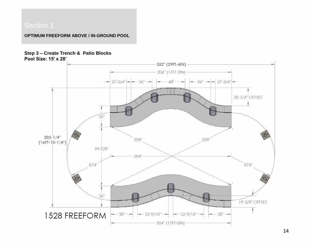
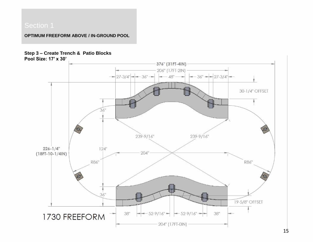
3.1 Create two trenches for the freeform section wall foundations.
• Trenches MUST be a minimum of 18-½” deep
• Trenches MUST be 36” wide (24” inward & 12” outward from wall center)
• Trenches MUST be the length listed on the specific footprint.
See following pages 13 through 16 for specific trench dimensions
and location.
3.2 Place concrete block support structures as illustrated in Figure 3.2 at
the locations specified on the following footprints on pages 13-16.
Each assembly is constructed from two patio blocks (1 5/8” actual)
and two masonry blocks (7 5/8” actual), giving a total stacked height
of 18 ½”. This is equal to the depth of the trench dug earlier.
3.3 Place patio blocks at each wall joint for the curved ends of the pool.
All patio blocks must be flush with the ground, solid and level with
each other in all directions. Patio blocks for pools installed deeper
than 24” below grade should be split to allow installation of rebar.
OPTIMUM FREEFORM ABOVE / IN-GROUND POOL
Section 1
Step 3 – Create Trench and Place Support Blocks
12
3.1
3.2Masonry
Blocks
Patio
Blocks
3.3 ABOVE GROUND 3.3 IN-GROUND
IMPORTANT! IT IS EXTREMELY IMPORTANT TO THE
STRUCTURAL STABILITY OF THE POOL THAT THE
CONCRETE DIMENSIONS ARE FOLLOWED EXACTLY.
FAILURE TO DO SO MAY VOID THE WARRANTY.
3.1

OPTIMUM FREEFORM ABOVE / IN-GROUND POOL
Section 1
Step 3 – Create Trench & Patio Blocks
Pool Size: 14’ x 23’
13
OPTIMUM FREEFORM ABOVE / IN-GROUND POOL
Section 1
Step 3 – Create Trench & Patio Blocks
Pool Size: 15’ x 28’
14
3.1
OPTIMUM FREEFORM ABOVE / IN-GROUND POOL
Section 1
Step 3 – Create Trench & Patio Blocks
Pool Size: 17’ x 30’
15
3.1

OPTIMUM FREEFORM ABOVE / IN-GROUND POOL
Section 1
Step 3 – Create Trench & Patio Blocks
Pool Size: 19’ x 32’
16
3.1
OPTIMUM FREEFORM ABOVE / IN-GROUND POOL
Section 1
Section 2
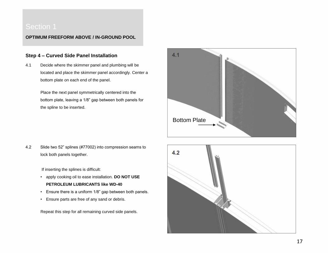
Step 4 – Curved Side Panel Installation
17
4.1 Decide where the skimmer panel and plumbing will be
located and place the skimmer panel accordingly. Center a
bottom plate on each end of the panel.
Place the next panel symmetrically centered into the
bottom plate, leaving a 1/8” gap between both panels for
the spline to be inserted.
4.2 Slide two 52” splines (#77002) into compression seams to
lock both panels together.
If inserting the splines is difficult:
• apply cooking oil to ease installation. DO NOT USE
PETROLEUM LUBRICANTS like WD-40
• Ensure there is a uniform 1/8” gap between both panels.
• Ensure parts are free of any sand or debris.
Repeat this step for all remaining curved side panels.
Bottom Plate

OPTIMUM FREEFORM ABOVE / IN-GROUND POOL
Section 1
Section 2
Step 4 – Curved Side Panel Installation
18
4.3 Ensure panels are centered and fully inserted into the
bottom plates.
At this time, on the curved side ONLY, drill 7/16" holes through
the pool panels at the bottom plate hole locations using the
bottom plate holes as a drill guide. Secure panels with 2-½” bolts
(#99-0137) and nuts (#99-0134).
4.4 INGROUND ONLY: If the pool installation is greater than
24” below grade, you must use the included rebar with a concrete
collar around the perimeter of the pool. Insert the rebar halfway
into the ground through the bottom plate holes before pouring the
concrete collar.
If the pool is less than 24” below grade, you may skip this step.
4.4
4.3

OPTIMUM FREEFORM ABOVE / IN-GROUND POOL
Section 1
Section 2
Step 4 – Curved Side Panel Installation
At this point in the installation process, the assembly should look similar to the image below.
19

OPTIMUM FREEFORM ABOVE / IN-GROUND POOL
Section 1
Section 2
Step 5 – Freeform Side Panel Installation
20
5.1 Place a bottom plate on the curved side panel which will transition
to the freeform side of the pool. Ensure bottom plate is fully seated
on panel and inserted 1-½” onto panel.
5.2 Drill a 7/16" hole through the panel using the bottom plate hole as a
drill guide. Secure bottom plate with one 2-½” bolt (#99-0137) and
nut (#99-0134).
5.3 Attach the straight panel connector (#77026) onto the curved
section of the pool as illustrated in Figure 5.3.
Two short splines (#77014), one extended spline (#77013) and one
52” spline (#77002) are used to attach the straight panel connector.
5.1 5.3
5.2
1-½”
short spline
extended spline
52” spline
straight panel
connector
OPTIMUM FREEFORM ABOVE / IN-GROUND POOL
Section 1
Section 2
Step 5 – Freeform Side Panel Installation
21
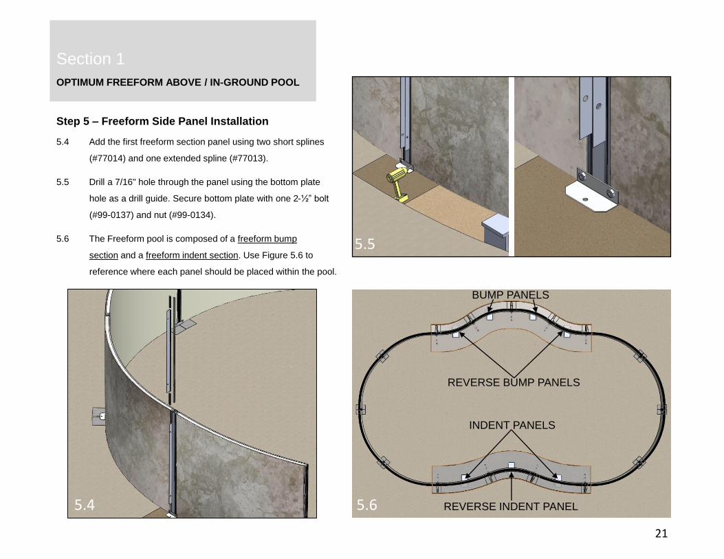
5.4 Add the first freeform section panel using two short splines
(#77014) and one extended spline (#77013).
5.5 Drill a 7/16" hole through the panel using the bottom plate
hole as a drill guide. Secure bottom plate with one 2-½” bolt
(#99-0137) and nut (#99-0134).
5.6 The Freeform pool is composed of a freeform bump
section and a freeform indent section. Use Figure 5.6 to
reference where each panel should be placed within the pool.
5.4
5.5
5.6
REVERSE BUMP PANELS
INDENT PANELS
BUMP PANELS
REVERSE INDENT PANEL
OPTIMUM FREEFORM ABOVE / IN-GROUND POOL
Section 1
Section 2
Step 5 – Freeform Side Panel Installation
22
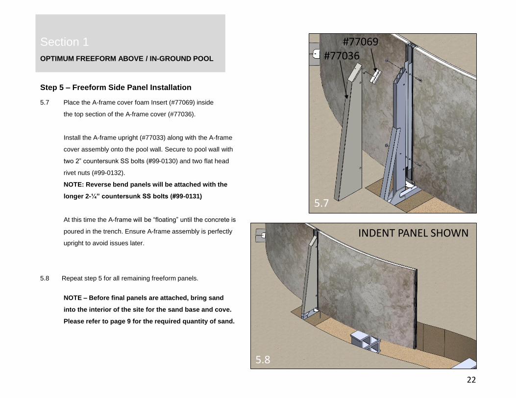
5.7 Place the A-frame cover foam Insert (#77069) inside
the top section of the A-frame cover (#77036).
Install the A-frame upright (#77033) along with the A-frame
cover assembly onto the pool wall. Secure to pool wall with
two 2” countersunk SS bolts (#99-0130) and two flat head
rivet nuts (#99-0132).
NOTE: Reverse bend panels will be attached with the
longer 2-¼” countersunk SS bolts (#99-0131)
At this time the A-frame will be “floating” until the concrete is
poured in the trench. Ensure A-frame assembly is perfectly
upright to avoid issues later.
5.8 Repeat step 5 for all remaining freeform panels.
NOTE – Before final panels are attached, bring sand
into the interior of the site for the sand base and cove.
Please refer to page 9 for the required quantity of sand.
5.7
5.8
INDENT PANEL SHOWN
#77069 #77036
OPTIMUM FREEFORM ABOVE / IN-GROUND POOL
Section 1
Section 2
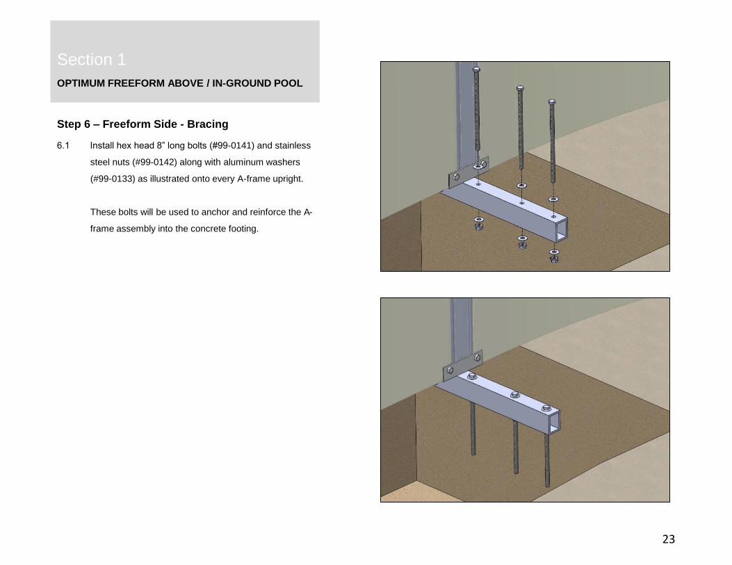
Step 6 – Freeform Side - Bracing
23
6.1 Install hex head 8” long bolts (#99-0141) and stainless
steel nuts (#99-0142) along with aluminum washers
(#99-0133) as illustrated onto every A-frame upright.
These bolts will be used to anchor and reinforce the A-
frame assembly into the concrete footing.

OPTIMUM FREEFORM ABOVE / IN-GROUND POOL
Section 1
Section 2
Step 6 – Freeform Side - Bracing
24
6.2 All reverse bend panels require bracing. There will be six
brace assemblies per freeform pool. Attach the left and right
mounting brackets (#77153 & #77155) with the hardware
installed previously to attach the A-frame upright. Install one
mounting bracket at a time to keep A-frame upright assembly
attached.
NOTE: Ensure the bolts at these locations are the longer
2¼” countersunk SS bolts (#99-0131).
6.3 Place the upper and lower freeform braces into the
mounting brackets. Once the pool is filled with water, they will
be located firmly in place.
6.2
6.2.1
6.3
(#99-0131)
REVERSE PANEL
OPTIMUM FREEFORM ABOVE / IN-GROUND POOL
Section 1
Section 2
25
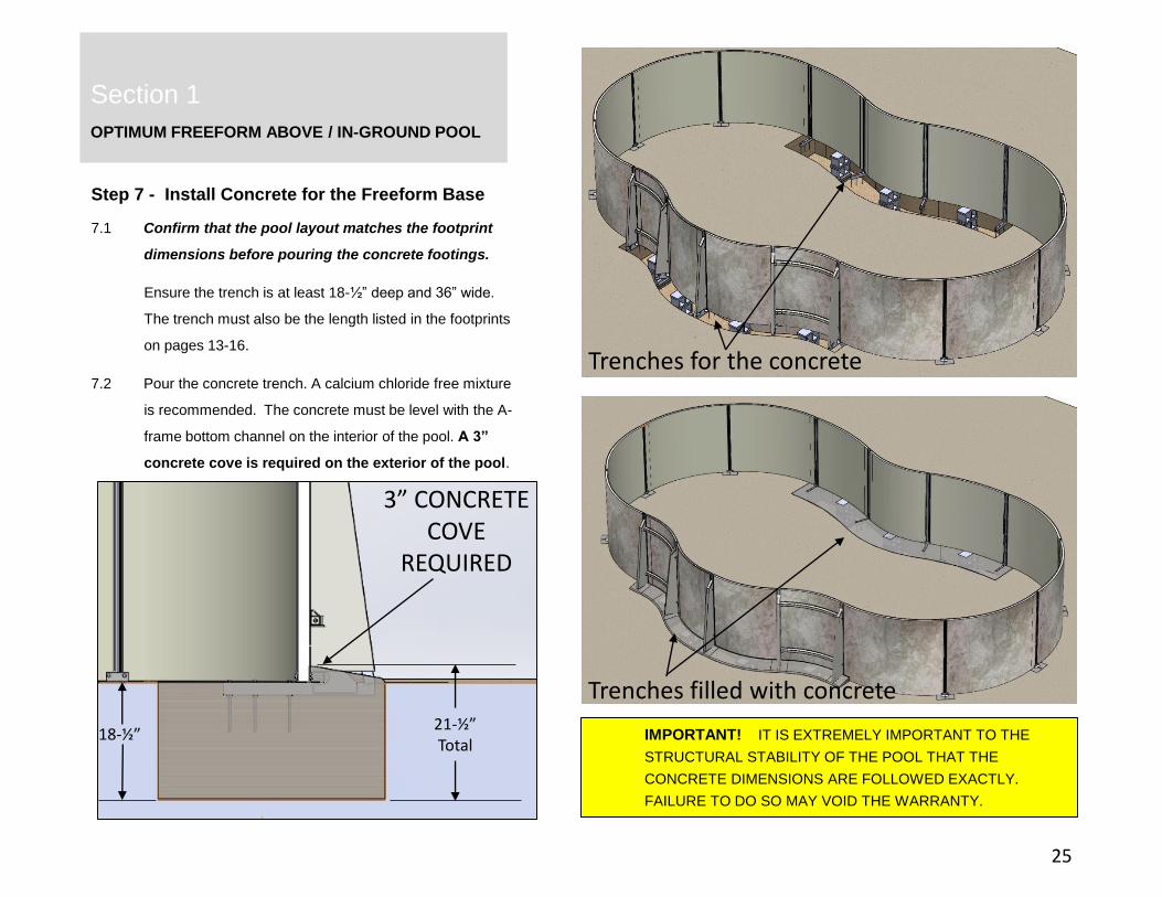
Step 7 - Install Concrete for the Freeform Base
7.1 Confirm that the pool layout matches the footprint
dimensions before pouring the concrete footings.
Ensure the trench is at least 18-½” deep and 36” wide.
The trench must also be the length listed in the footprints
on pages 13-16.
7.2 Pour the concrete trench. A calcium chloride free mixture
is recommended. The concrete must be level with the A-
frame bottom channel on the interior of the pool. A 3”
concrete cove is required on the exterior of the pool.
Trenches filled with concrete
Trenches for the concrete
IMPORTANT! IT IS EXTREMELY IMPORTANT TO THE
STRUCTURAL STABILITY OF THE POOL THAT THE
CONCRETE DIMENSIONS ARE FOLLOWED EXACTLY.
FAILURE TO DO SO MAY VOID THE WARRANTY.
18-½”21-½”Total
3” CONCRETE COVE
REQUIRED
OPTIMUM FREEFORM ABOVE / IN-GROUND POOL
Section 1
Section 2
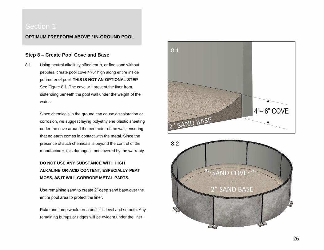
Step 8 – Create Pool Cove and Base
26
8.1 Using neutral alkalinity sifted earth, or fine sand without
pebbles, create pool cove 4”-6” high along entire inside
perimeter of pool. THIS IS NOT AN OPTIONAL STEP
See Figure 8.1. The cove will prevent the liner from
distending beneath the pool wall under the weight of the
water.
Since chemicals in the ground can cause discoloration or
corrosion, we suggest laying polyethylene plastic sheeting
under the cove around the perimeter of the wall, ensuring
that no earth comes in contact with the metal. Since the
presence of such chemicals is beyond the control of the
manufacturer, this damage is not covered by the warranty.
DO NOT USE ANY SUBSTANCE WITH HIGH
ALKALINE OR ACID CONTENT, ESPECIALLY PEAT
MOSS, AS IT WILL CORRODE METAL PARTS.
Use remaining sand to create 2” deep sand base over the
entire pool area to protect the liner.
Rake and tamp whole area until it is level and smooth. Any
remaining bumps or ridges will be evident under the liner.
2” SAND BASE
SAND COVE
4”– 6” COVE
8.1
8.2

OPTIMUM FREEFORM ABOVE / IN-GROUND POOL
Section 1
Section 2
Step 9 – Skimmer Installation
27
9.1 Use the specific gray and white skimmer mounting plates for
for the above ground skimmer or in-ground skimmer.
9.2 Place gray skimmer mounting plate assembly on the inside of
the pool, and white skimmer mounting plate on the outside of
the panel, sandwiching the skimmer inside the wall panel
cutout. Ensure gaskets are located as illustrated.
Loosely secure assembly with five 2-¼” countersunk bolts
(#99-0131) and flat-head rivet nuts (#99-0132).
Ensure plates are centered and level, then tighten hardware,
taking care not to overtighten.
9.3 With hardware provided in the skimmer kit, secure skimmer
to the gray skimmer plate with 4 screws. Do not fully tighten
as these screws will be removed later.
NOTE: Skimmer face plate (in skimmer assembly) and
remaining screws will be attached after pool liner is installed,
locking the skimmer firmly in place. Refer to skimmer kit
installation instructions for more information.
Above Ground
In-Ground
cork gaskets
silicon gasket
OPTIMUM FREEFORM ABOVE / IN-GROUND POOL
Section 1
Section 2
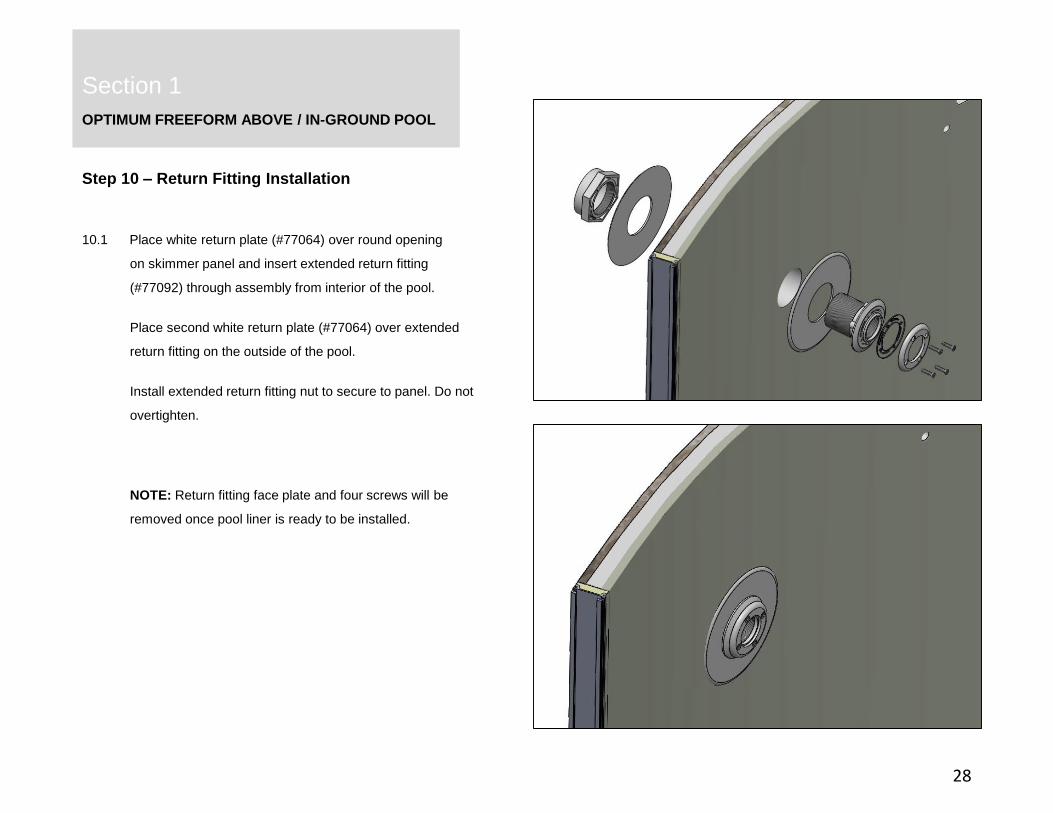
Step 10 – Return Fitting Installation
28
10.1 Place white return plate (#77064) over round opening
on skimmer panel and insert extended return fitting
(#77092) through assembly from interior of the pool.
Place second white return plate (#77064) over extended
return fitting on the outside of the pool.
Install extended return fitting nut to secure to panel. Do not
overtighten.
NOTE: Return fitting face plate and four screws will be
removed once pool liner is ready to be installed.

OPTIMUM FREEFORM ABOVE / IN-GROUND POOL
Section 1
Section 2
29
Step 11 - Installing Top Coping
Above Ground Coping
11.1 Place 2" PVC top coping onto each pool panel, leaving a
½” gap between each length. Coping should be offset from
wall panel joints by 2" as shown in Figure 11.1.
11.2 Each length of top coping will be attached to the pool with
screws from the exterior side of the pool only. Drill evenly
spaced 1/8" pilot holes through the top coping and exterior
pool wall, ensuring the top coping is fully seated.
Attach the top coping to the pool panels with colored head cap
screws #8 x ½” (#99-0138). DO NOT OVERTIGHTEN.
Spacing should be every 12-18”.
11.1
11.2
OPTIMUM FREEFORM ABOVE / IN-GROUND POOL
Section 1
Section 2
30
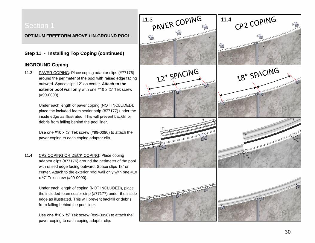
Step 11 - Installing Top Coping (continued)
INGROUND Coping
11.3 PAVER COPING: Place coping adaptor clips (#77176)
around the perimeter of the pool with raised edge facing
outward. Space clips 12” on center. Attach to the
exterior pool wall only with one #10 x ¾” Tek screw
(#99-0090).
Under each length of paver coping (NOT INCLUDED),
place the included foam sealer strip (#77177) under the
inside edge as illustrated. This will prevent backfill or
debris from falling behind the pool liner.
Use one #10 x ¾” Tek screw (#99-0090) to attach the
paver coping to each coping adaptor clip.
11.4 CP2 COPING OR DECK COPING: Place coping
adaptor clips (#77176) around the perimeter of the pool
with raised edge facing outward. Space clips 18” on
center. Attach to the exterior pool wall only with one #10
x ¾” Tek screw (#99-0090).
Under each length of coping (NOT INCLUDED), place
the included foam sealer strip (#77177) under the inside
edge as illustrated. This will prevent backfill or debris
from falling behind the pool liner.
Use one #10 x ¾” Tek screw (#99-0090) to attach the
paver coping to each coping adaptor clip.
11.3 11.4

OPTIMUM FREEFORM / IN-GROUND POOL
Section 1
31
Step 11 - Installing Top Coping (continued)
11.5 For pools that are installed into a hillside and will utilize
both 2” PVC top coping and CP2 coping as illustrated
below, there is a transition kit available (#77268). This kit
includes two stainless steel plates to cap off the ends of the
CP2 coping to give a finished edge.
Bend the lower tab on the end plate as seen in Figure 11.5.
Attach the end plate with #10 x ¾” Tek screw (#99-0090)
through the CP2 coping and into the coping adaptor clip
(#77176). Repeat on the opposite end.
11.5
11.6
CP2 END CAPS#77268

OPTIMUM FREEFORM ABOVE / IN-GROUND POOL
Section 1
Section 2
32
Step 12 - Install Concrete Collar
12.1 IN-GROUND ONLY: All pools that are buried more
than 24” below grade require a concrete collar, 12” wide
by 8” high, around the entire perimeter of the pool. If extra
supports are required for patio or other pool features,
consider installing them before pouring the concrete.
If the pool is installed into a hill, as illustrated in Figure
12.2, the pool still requires a concrete collar 12” wide by
8” high at any location where the pool is buried more than
24” below grade. Taper the ends of the concrete collar
once the depth below grade becomes less than 24”.
Concrete Collar8” high x 12” wide
12.2
12.1

OPTIMUM FREEFORM ABOVE / INGROUND POOL
Section 1
Section 2
Step 13 – Install liner
33
13.1 Ensure sand in pool is level with no impressions.
Remove liner (NOT INCLUDED) from carton and unfold liner
outside of the pool.
Loosely refold liner and gently place it in the pool, taking care to
not disturb the smoothed sand base of the pool.
While standing outside of the pool, snap liner bead into coping
receiver track around entire pool. Remove as many wrinkles
from the liner as possible as you go by gently tugging on the
liner or using a soft broom. A shop vacuum can be used to
remove wrinkles by attaching the vacuum hose to the skimmer
outlet and sealing with duct tape. Remove vacuum once pool
has 6” of water.
Step 14 – Install Coping Clips
13.1
14.1
14.1 Install coping clips (#77310) onto top coping by inserting
interior lip first, then snapping into place.
CP2 coping clips (NOT INCLUDED) – install coping clips by
first catching top edge then pressing down firmly to lock in
place.
POOL LINER
OPTIMUM FREEFORM ABOVE / INGROUND POOL
Section 1
Section 2
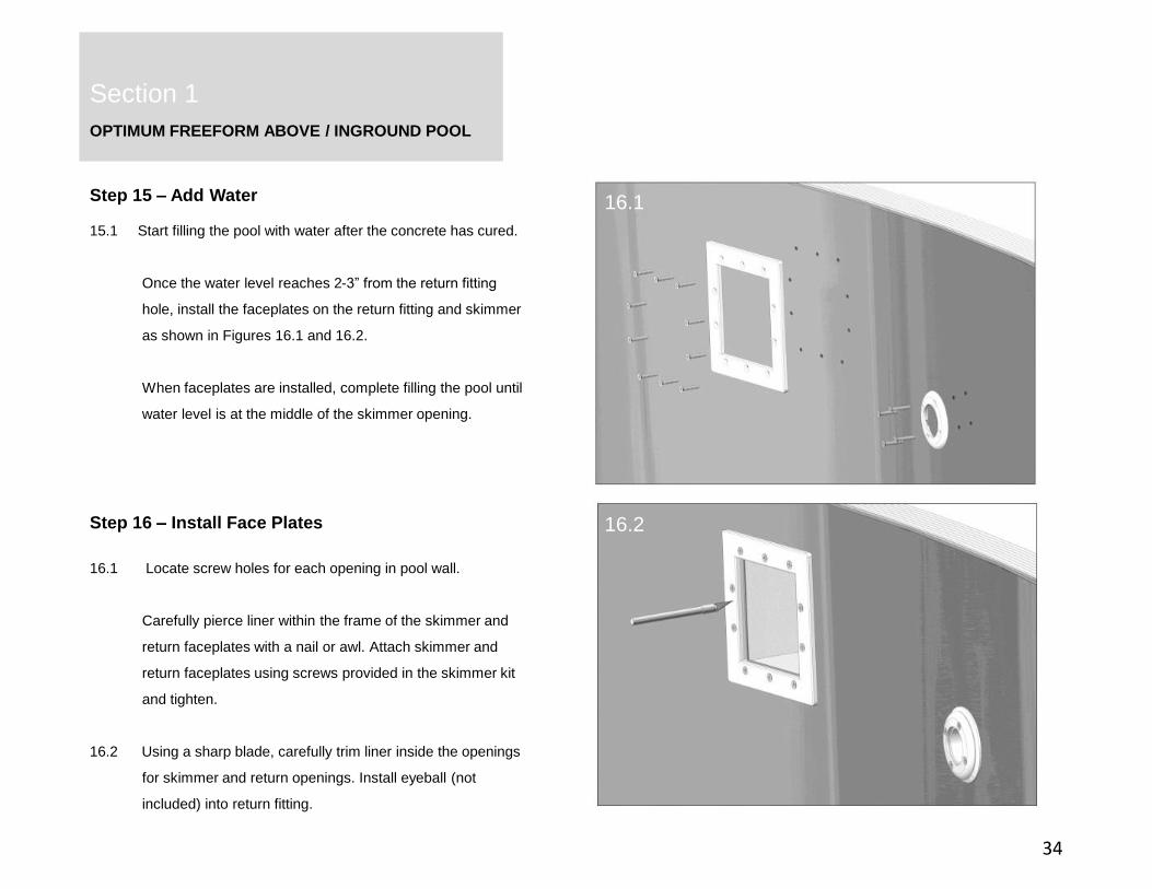
Step 15 – Add Water
34
15.1 Start filling the pool with water after the concrete has cured.
Once the water level reaches 2-3” from the return fitting
hole, install the faceplates on the return fitting and skimmer
as shown in Figures 16.1 and 16.2.
When faceplates are installed, complete filling the pool until
water level is at the middle of the skimmer opening.
Step 16 – Install Face Plates
16.1 Locate screw holes for each opening in pool wall.
Carefully pierce liner within the frame of the skimmer and
return faceplates with a nail or awl. Attach skimmer and
return faceplates using screws provided in the skimmer kit
and tighten.
16.2 Using a sharp blade, carefully trim liner inside the openings
for skimmer and return openings. Install eyeball (not
included) into return fitting.
16.1
16.2
OPTIMUM FREEFORM ABOVE / INGROUND POOL
Section 1
Section 2
35
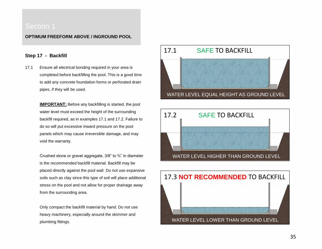
Step 17 - Backfill
17.1 Ensure all electrical bonding required in your area is
completed before backfilling the pool. This is a good time
to add any concrete foundation forms or perforated drain
pipes, if they will be used.
IMPORTANT: Before any backfilling is started, the pool
water level must exceed the height of the surrounding
backfill required, as in examples 17.1 and 17.2. Failure to
do so will put excessive inward pressure on the pool
panels which may cause irreversible damage, and may
void the warranty.
Crushed stone or gravel aggregate, 3/8” to ¾” in diameter
is the recommended backfill material. Backfill may be
placed directly against the pool wall. Do not use expansive
soils such as clay since this type of soil will place additional
stress on the pool and not allow for proper drainage away
from the surrounding area.
Only compact the backfill material by hand. Do not use
heavy machinery, especially around the skimmer and
plumbing fittings.
17.1 SAFE TO BACKFILL
17.2 SAFE TO BACKFILL
17.3 NOT RECOMMENDED TO BACKFILL
WATER LEVEL EQUAL HEIGHT AS GROUND LEVEL
WATER LEVEL LOWER THAN GROUND LEVEL
WATER LEVEL HIGHER THAN GROUND LEVEL
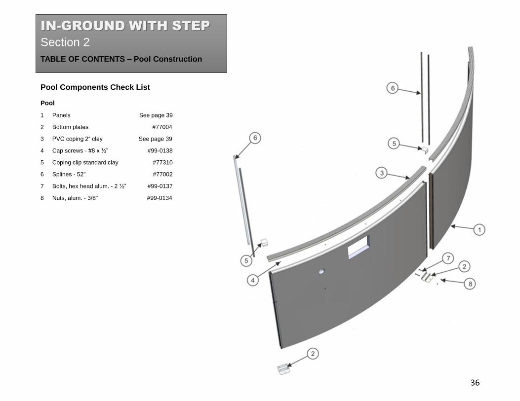
TABLE OF CONTENTS – Pool Construction
Pool
1 Panels See page 39
2 Bottom plates #77004
3 PVC coping 2“ clay See page 39
4 Cap screws - #8 x ½” #99-0138
5 Coping clip standard clay #77310
6 Splines - 52" #77002
7 Bolts, hex head alum. - 2 ½” #99-0137
8 Nuts, alum. - 3/8" #99-0134
Section 2
Section 2
Pool Components Check List
36
IN-GROUND WITH STEP
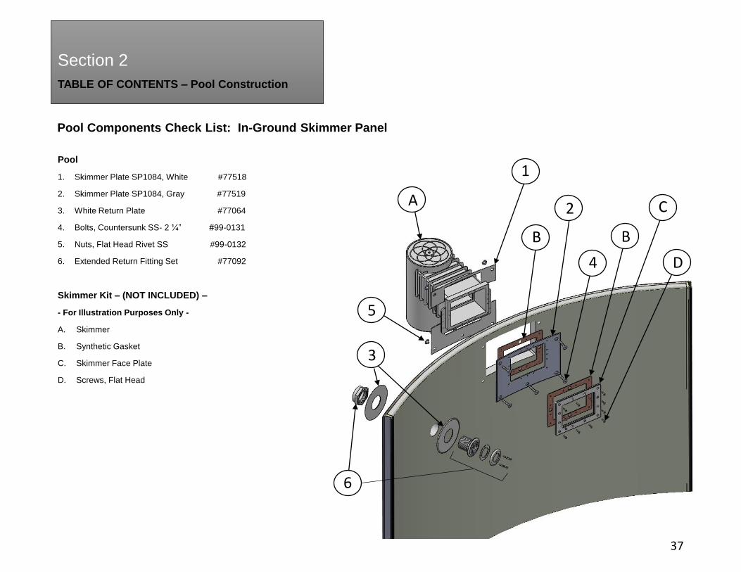
TABLE OF CONTENTS – Pool Construction
Section 2
Pool Components Check List: In-Ground Skimmer Panel
37
Pool
1. Skimmer Plate SP1084, White #77518
2. Skimmer Plate SP1084, Gray #77519
3. White Return Plate #77064
4. Bolts, Countersunk SS- 2 ¼” #99-0131
5. Nuts, Flat Head Rivet SS #99-0132
6. Extended Return Fitting Set #77092
Skimmer Kit – (NOT INCLUDED) –
- For Illustration Purposes Only -
A. Skimmer
B. Synthetic Gasket
C. Skimmer Face Plate
D. Screws, Flat Head
D
C
B
A
6
5
4
3
2
1
B

TABLE OF CONTENTS – Pool Construction
Step Assembly
18. Step filler panel See Page 39
19. Nuts, hex flange 3/8” SS #10660
6. Splines, 52” #77002
20. Step rod extrusion 52” #77173
21. Bolts, hex flange 3/8” x 1” SS #99-0104
22. Step socket extrusion 52” #77143
23. Step fender washers 3/8” x 1-¾” #77175
24. Radius step (NOT INCLUDED) -
25. Step bottom plate, right #77142
26. Step bottom plate, left #77141
15. Rebar 3/8” x 15” #77001
27. Step diagonal brace 18” #77146
28. Short splines 5-¾” #77014
29. Step horizontal brace 37-13/16” #77148
30. Extended spline 40-½” #77013
Section 2
Section 2
Step Components Check List
38
27 26
24
23
2418 19
6
2021 22
29
15
30
28
25
IMPORTANT:FREEFORM POOLS MUST USE
THE 91-¾” WIDE RADIUS STEP.
OPTIMUM FREEFORM IN-GROUND WITH STEP
Section 2
Parts Per Pool Size
39
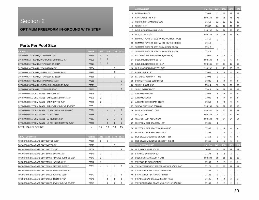
COMPONENTS Part No 1423 1528 1730 1932
3 BOTTOM PLATE 77004 12 13 13 15
4 CAP SCREWS - #8 X ½" 99-0138 60 75 75 75
5 COPING CLIP STANDARD CLAY 77310 12 13 13 15
6 SPLINE - 52" 77002 24 26 26 30
7 BOLT, HEX HEAD ALUM. - 2-½" 99-0137 24 26 26 30
8 NUT, ALUM. - 3/8" 99-0134 24 26 26 30
9 SLIMMER PLATE SP 1091 WHITE (OUTSIDE POOL) 775161 1 1 1
10 SKIMMER PLATE SP 1084 WHITE (OUTSIDE POOL) 77518
11 SKIMMER PLATE SP 1091 GRAY (INSIDE POOL) 775171 1 1 1
1. PANELS Part No 1423 1528 1730 1932 12 SKIMMER PLATE SP 1084 GRAY (INSIDE POOL) 77519
OPTIMUM 12FT PANEL, STANDARD 72-¼" 77319 3 3 13 RETURN PLATE WHITE (INSIDE/OUTSIDE) 77064 2 2 2 2
OPTIMUM 12FT PANEL, INGROUND SKIMMER 72-¼" 77320 1 1 14 BOLT, COUNTERSUNK SS - 2" 99-0130 4 6 6 6
OPTIMUM 12FT PANEL, STEP FILLER 24-3/16" 77323 2 2 15 BOLT, COUNTERSUNK SS - 2-¼" 99-0131 17 17 17 17
OPTIMUM 14FT PANEL, STANDARD 84-¼" 77334 3 16 NUT, FLAT HEAD RIVET SS - 3/8" 99-0132 21 23 23 23
OPTIMUM 14FT PANEL, INGROUND SKIMMER 84-¼" 77335 1 17 REBAR - 3/8 X 15" 77001 4 4 4 6
OPTIMUM 14FT PANEL, STEP FILLER 37-15/16" 77338 2 18 EXTENDED RETURN FITTING 77092 1 1 1 1
OPTIMUM 16FT PANEL, STANDARD 73-7/16" 77055 5 19 STRAIGHT PANEL CONNECTOR 77026 8 9 9 9
OPTIMUM 16FT PANEL, INGROUND SKIMMER 73-7/16" 77071 1 20 SPLINE, SHORT 5-¾" 77014 32 36 36 36
OPTIMUM 16FT PANEL, STEP FILLER 26-¼" 77133 2 21 SPINE, EXTENDED 52" 77013 16 18 18 18
OPTIMUM FREEFORM PANEL - SM BUMP 57" 77378 1 22 A-FRAME UPRIGHT 77033 8 9 9 9
OPTIMUM FREEFORM PANEL - SM REVERSE BUMP 35-¼" 77379 2 23 A-FRAME COVER 77036 8 9 9 9
OPTIMUM FREEFORM PANEL - SM INDENT 38-5/8" 77380 2 24 A-FRAME COVER FOAM INSERT 77069 8 9 9 9
OPTIMUM FREEFORM PANEL - SM REVERSE INDENT 46-9/16" 77381 1 25 SCREW, FLAT HEAD 2" LONG 99-0130 16 18 18 18
OPTIMUM FREEFORM PANEL - LG REVERSE BUMP 46-9/16" 77381 2 2 2 26 BOLT, HEX HEAD 8" LONG 99-0141 24 27 27 27
OPTIMUM FREEFORM PANEL - LG BUMP 50" 77386 2 2 2 27 NUT, 3/8" SS 99-0142 24 27 27 27
OPTIMUM FREEFORM PANEL - LG INDENT 64-½" 77387 2 2 2 28 WASHER - 7/8" ALUMINUM 99-0133 48 54 54 54
OPTIMUM FREEFORM PANEL - LG REVERSE INDENT 56-5/16" 77388 1 1 1 29 FREEFORM SIDE BRACE SM - 35" 77395 4
TOTAL PANEL COUNT - 12 13 13 15 30 FREEFORM SIDE BRACE SM/LG - 46-¾" 77396 2 4 4 4
31 FREEFORM SIDE BRACE LG - 57-¼" 77397 2 2 2
2. PVC TOP COPING Part No 1423 1528 1730 1932 32 SIDE BRACE MOUNTING BRACKET - LEFT 77153 6 6 6 6
PVC COPING STANDARD CLAY 12FT 78-3/16" 77309 6 6 33 SIDE BRACE MOUNTING BRACKET - RIGHT 77155 6 6 6 6
PVC COPING STANDARD CLAY 14FT 90-¾" 77325 6 STEP COMPONENTS Part No 1423 1528 1730 1932
PVC COPING STANDARD CLAY 16FT 77-1/8" 77006 8 34 NUT, HEX FLANGE 3/8" SS 10660 18 18 18 18
PVC COPING STANDARD CLAY SMALL BUMP 61-¾" 77340 1 35 STEP ROD EXTENSION 52" 77173 2 2 2 2
PVC COPING STANDARD CLAY SMALL REVERSE BUMP 38-5/8" 77341 2 36 BOLT, HEX FLANGE 3/8" X 1" SS 99-0104 18 18 18 18
PVC COPING STANDARD CLAY SMALL INDENT 41-½" 77342 1 37 STEP SOCKET EXTRUSION 52" 77143 2 2 2 2
PVC COPING STANDARD CLAY SMALL REVERSE INDENT 77343 2 2 2 2 38 STEP ATTACHEMENT FENDER WASHER 3/8" X 1-¾" 77175 12 12 12 12
PVC COPING STANDARD CLAY LARGE REVERSE BUMP 50" 39 STEP ANCHOR PLATE MODIFIED RIGHT 77142 1 1 1 1
PVC COPING STANDARD CLAY LARGE BUMP 53-7/16" 77347 2 2 2 40 STEP ANCHOR PLATE MODIFIED LEFT 77141 1 1 1 1
PVC COPING STANDARD CLAY LARGE INDENT 67-¾" 77348 1 1 1 41 STEP DIAGONAL BRACE ANGLE 18" PIECE 77146 2 2 2 2
PVC COPING STANDARD CLAY LARGE REVESE INDENT 60-7/8" 77349 2 2 2 42 STEP HORIZONTAL BRACE ANGLE 37-13/16" PIECE 77148 2 2 2 2

OPTIMUM FREEFORM IN-GROUND WITH STEP
Section 2
40
Tools You Will Need:
Tape measure - 100'
Marking spray paint or powder
String - 25’ length
Stake or peg – 12”
Transit, laser level or 3’ level
Rubber mallet
Hacksaw
Spade
Square shovel
Pick
Rake
Tamper square 10” or 12”
2x4, straight - 12’
Square
Power drill
7/16" and 1/8 drill bits
¼" hex nut driver bit
Socket set
Duct tape
Pliers - channel lock
9/16" open end wrench
Screwdrivers, flat & Phillips
Metal file
Utility knife
PVC pipe cutter
Pool trowel
Cloth rag
Cooking spray
Shop vacuum
Soft bristle broom
Extension cord
Hose with spray nozzle
Wheelbarrow
Also Needed But Not Included:
Patio blocks - (2” x 12” x 12”)
Masonry Blocks - (8” x 8” x 16”)
Backfill (crushed stone or gravel 3/8” – ¾” diameter)
Perforated drain pipe (for drainage if the site floods easily)
Masonry Sand
Concrete
Pool
Size
Masonry
Sand Cubic
Yards
Patio
Blocks
Masonry
Blocks
Concrete
Footing Cubic
Yards
Concrete
Collar - STEP
SUPPORT -
Cubic Yards
1423 1.7 17 12 4-½ 3
1528 2.1 19 14 6-½ 3-¼
1730 2.6 19 14 6-½ 3-½
1932 3.1 21 14 6-½ 3-¾
*Note – pools with steps, add concrete footing and concrete collar for total
quantity needed.
OPTIMUM FREEFORM INGROUND WITH STEP
Section 2
Section 2
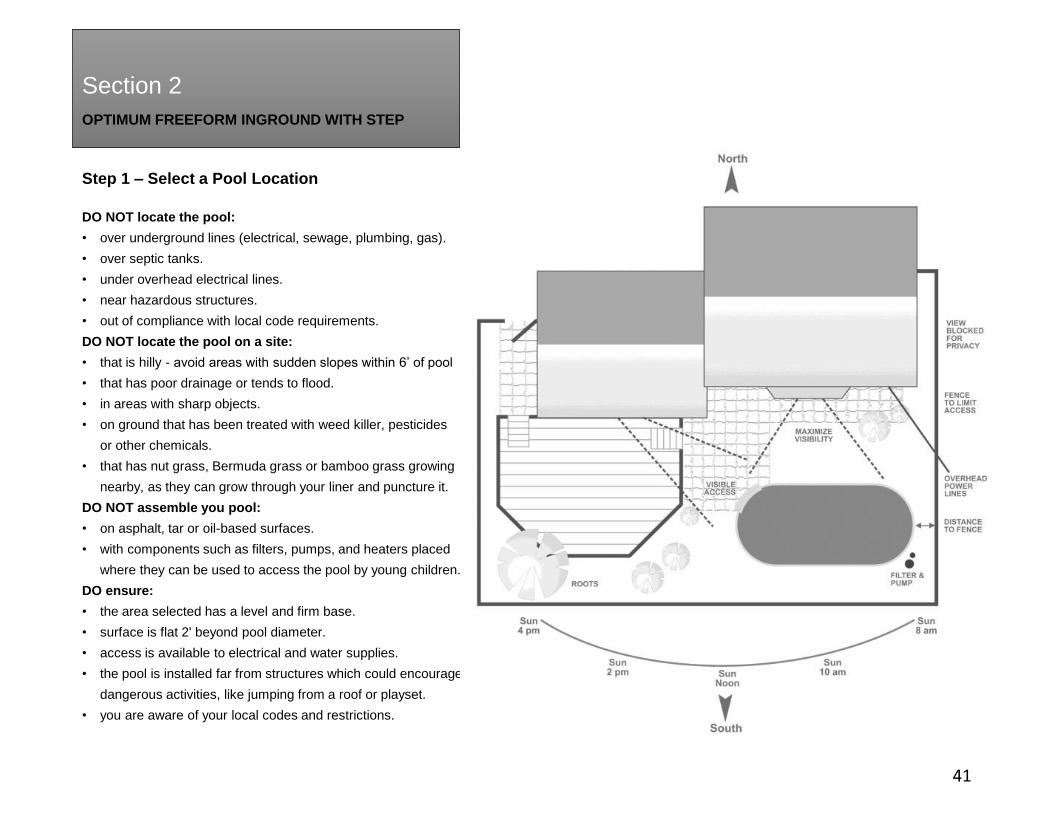
Step 1 – Select a Pool Location
41
DO NOT locate the pool:
• over underground lines (electrical, sewage, plumbing, gas).
• over septic tanks.
• under overhead electrical lines.
• near hazardous structures.
• out of compliance with local code requirements.
DO NOT locate the pool on a site:
• that is hilly - avoid areas with sudden slopes within 6’ of pool
• that has poor drainage or tends to flood.
• in areas with sharp objects.
• on ground that has been treated with weed killer, pesticides
or other chemicals.
• that has nut grass, Bermuda grass or bamboo grass growing
nearby, as they can grow through your liner and puncture it.
DO NOT assemble you pool:
• on asphalt, tar or oil-based surfaces.
• with components such as filters, pumps, and heaters placed
where they can be used to access the pool by young children.
DO ensure:
• the area selected has a level and firm base.
• surface is flat 2' beyond pool diameter.
• access is available to electrical and water supplies.
• the pool is installed far from structures which could encourage
dangerous activities, like jumping from a roof or playset.
• you are aware of your local codes and restrictions.
OPTIMUM FREEFORM IN-GROUND WITH STEP
Section 2
Section 2
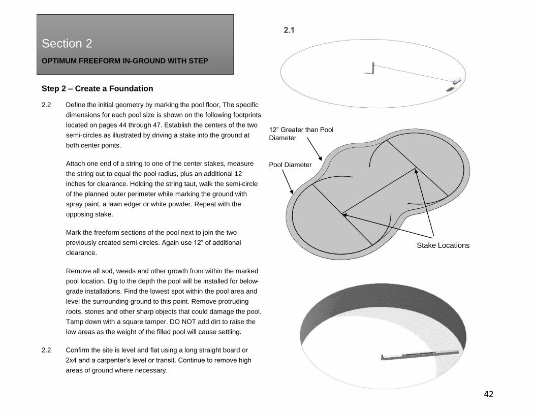
Step 2 – Create a Foundation
42
2.2 Define the initial geometry by marking the pool floor, The specific
dimensions for each pool size is shown on the following footprints
located on pages 44 through 47. Establish the centers of the two
semi-circles as illustrated by driving a stake into the ground at
both center points.
Attach one end of a string to one of the center stakes, measure
the string out to equal the pool radius, plus an additional 12
inches for clearance. Holding the string taut, walk the semi-circle
of the planned outer perimeter while marking the ground with
spray paint, a lawn edger or white powder. Repeat with the
opposing stake.
Mark the freeform sections of the pool next to join the two
previously created semi-circles. Again use 12” of additional
clearance.
Remove all sod, weeds and other growth from within the marked
pool location. Dig to the depth the pool will be installed for below-
grade installations. Find the lowest spot within the pool area and
level the surrounding ground to this point. Remove protruding
roots, stones and other sharp objects that could damage the pool.
Tamp down with a square tamper. DO NOT add dirt to raise the
low areas as the weight of the filled pool will cause settling.
2.2 Confirm the site is level and flat using a long straight board or
2x4 and a carpenter’s level or transit. Continue to remove high
areas of ground where necessary.
Stake Locations
Pool Diameter
12” Greater than Pool
Diameter
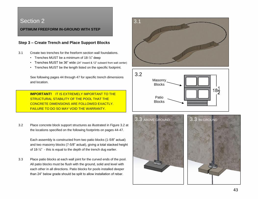
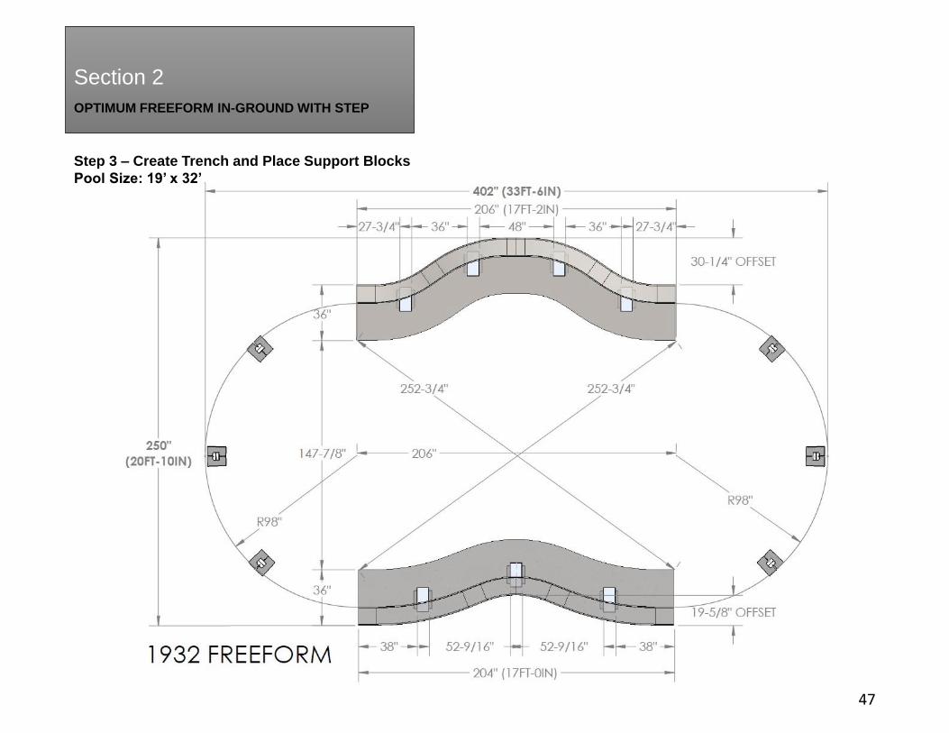
3.1 Create two trenches for the freeform section wall foundations.
• Trenches MUST be a minimum of 18-½” deep
• Trenches MUST be 36” wide (24” inward & 12” outward from wall center)
• Trenches MUST be the length listed on the specific footprint.
See following pages 44 through 47 for specific trench dimensions
and location.
3.2 Place concrete block support structures as illustrated in Figure 3.2 at
the locations specified on the following footprints on pages 44-47.
Each assembly is constructed from two patio blocks (1-5/8” actual)
and two masonry blocks (7-5/8” actual), giving a total stacked height
of 18-½” - this is equal to the depth of the trench dug earlier.
3.3 Place patio blocks at each wall joint for the curved ends of the pool.
All patio blocks must be flush with the ground, solid and level with
each other in all directions. Patio blocks for pools installed deeper
than 24” below grade should be split to allow installation of rebar.
OPTIMUM FREEFORM IN-GROUND WITH STEP
Section 2
Step 3 – Create Trench and Place Support Blocks
43
3.1
3.2Masonry
Blocks
Patio
Blocks
3.3 ABOVE GROUND 3.3 IN-GROUND
IMPORTANT! IT IS EXTREMELY IMPORTANT TO THE
STRUCTURAL STABILITY OF THE POOL THAT THE
CONCRETE DIMENSIONS ARE FOLLOWED EXACTLY.
FAILURE TO DO SO MAY VOID THE WARRANTY.
3.1

OPTIMUM FREEFORM IN-GROUND WITH STEP
Section 2
Step 3 – Create Trench and Place Support Blocks
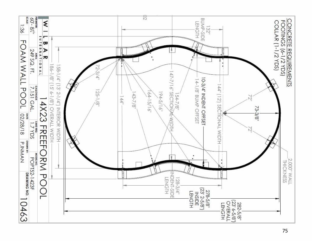
Pool Size: 14’ x 23’
44

OPTIMUM FREEFORM IN-GROUND WITH STEP
Section 2
Step 3 – Create Trench and Place Support Blocks
Pool Size: 15’ x 28’
45
3.1

OPTIMUM FREEFORM IN-GROUND WITH STEP
Section 2
Step 3 – Create Trench and Place Support Blocks
Pool Size: 17’ x 30’
46
3.1
OPTIMUM FREEFORM IN-GROUND WITH STEP
Section 2
Step 3 – Create Trench and Place Support Blocks
Pool Size: 19’ x 32’
47
3.1

OPTIMUM FREEFORM IN-GROUND WITH STEP
Section 2
Step 4 – Curved Side Panel Assembly - Location of Step
48
4.1 At this time, determine where the step will be placed
within the pool and place the step within this general
vicinity.
The 14’x23’, 15’x28’ and 17’x30’ freeform pools have
four possible locations for the step.
The 19’x32’ freeform pool has six different possible
locations for the step.
19’x 32’
14’x23’, 15’x28’ & 17’x30’
OPTIMUM FREEFORM IN-GROUND WITH STEP
Section 2
Section 2
Step 4 – Curved Side Panel Assembly
49
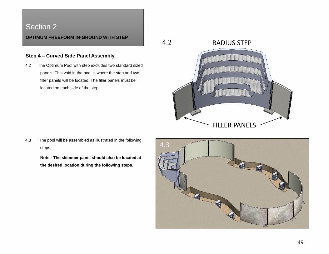
4.2 The Optimum Pool with step excludes two standard sized
panels. This void in the pool is where the step and two
filler panels will be located. The filler panels must be
located on each side of the step.
4.3 The pool will be assembled as illustrated in the following
steps.
Note - The skimmer panel should also be located at
the desired location during the following steps.
4.3
4.4
FILLER PANELS
RADIUS STEP4.2
4.3

OPTIMUM FREEFORM IN-GROUND WITH STEP
Section 2
Section 2
Step 4 – Curved Side Panel Assembly
50
4.4 Decide where the skimmer panel and plumbing will be
located and place the skimmer panel accordingly. Center a
bottom plate on each end of the panel.
Place the next panel symmetrically centered into the
bottom plate, leaving a 1/8” gap between both panels for
the spline to be inserted.
4.5 Slide two 52” splines (#77002) into compression seams to
lock both panels together.
If inserting the splines is difficult:
• apply cooking oil to ease installation. DO NOT USE
PETROLEUM LUBRICANTS like WD-40
• Ensure there is a uniform 1/8” gap between both panels.
• Check parts are free of any sand or debris.
Repeat this step for all remaining curved side panels.
Bottom Plate
4.4
4.5

OPTIMUM FREEFORM IN-GROUND WITH STEP
Section 2
Section 2
Step 4 – Curved Side Panel Assembly
51
4.6 Assemble shorter filler panels on each side of the void
where the step will be placed using two 52” splines (#77002)
and a bottom plate (#77004). Refer to the previous steps 4.3
and 4.4.
Note: Filler panels must be located on each side of the step.
4.7 At this time the pool assembly should look similar to Figure
4.6 with the step void located at the desired location.
Possible step locations are outlined on page 48.
4.6
4.7
OPTIMUM FREEFORM IN-GROUND WITH STEP
Section 2
Section 2
Step 4 – Curved Side Panel Assembly
52
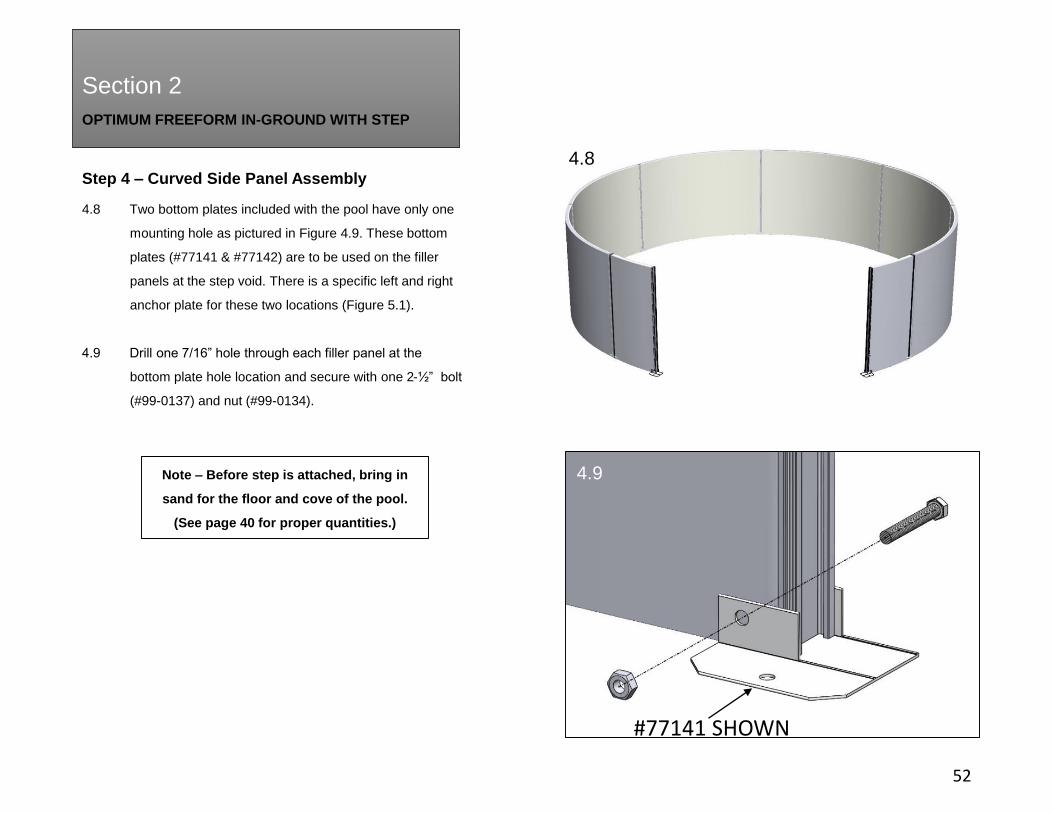
4.8 Two bottom plates included with the pool have only one
mounting hole as pictured in Figure 4.9. These bottom
plates (#77141 & #77142) are to be used on the filler
panels at the step void. There is a specific left and right
anchor plate for these two locations (Figure 5.1).
4.9 Drill one 7/16” hole through each filler panel at the
bottom plate hole location and secure with one 2-½” bolt
(#99-0137) and nut (#99-0134).
4.8
4.9Note – Before step is attached, bring in
sand for the floor and cove of the pool.
(See page 40 for proper quantities.)
#77141 SHOWN
OPTIMUM FREEFORM IN-GROUND WITH STEP
Section 2
Section 2
Step 4 – Curved Side Panel Assembly
53
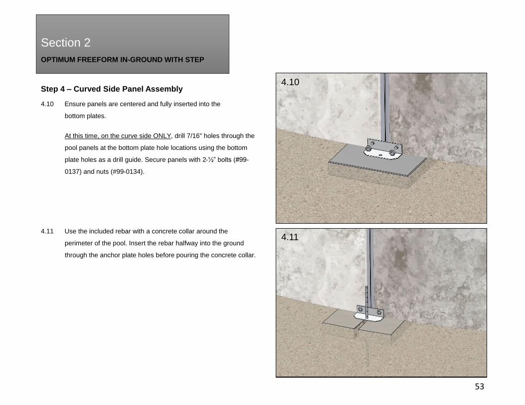
4.10 Ensure panels are centered and fully inserted into the
bottom plates.
At this time, on the curve side ONLY, drill 7/16" holes through the
pool panels at the bottom plate hole locations using the bottom
plate holes as a drill guide. Secure panels with 2-½” bolts (#99-
0137) and nuts (#99-0134).
4.11 Use the included rebar with a concrete collar around the
perimeter of the pool. Insert the rebar halfway into the ground
through the anchor plate holes before pouring the concrete collar.
4.11
4.10
OPTIMUM FREEFORM IN-GROUND WITH STEP
Section 2
Section 2
Step 5 – Step Installation on Curved Side
54
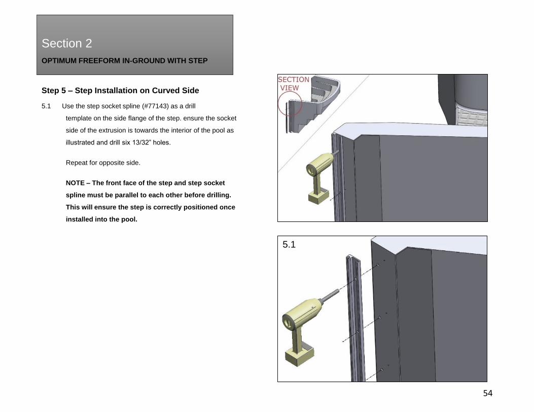
5.1 Use the step socket spline (#77143) as a drill
template on the side flange of the step. ensure the socket
side of the extrusion is towards the interior of the pool as
illustrated and drill six 13/32” holes.
Repeat for opposite side.
NOTE – The front face of the step and step socket
spline must be parallel to each other before drilling.
This will ensure the step is correctly positioned once
installed into the pool.
5.1
OPTIMUM FREEFORM IN-GROUND WITH STEP
Section 2
Section 2
Step 5 – Step Installation on Curved Side
55
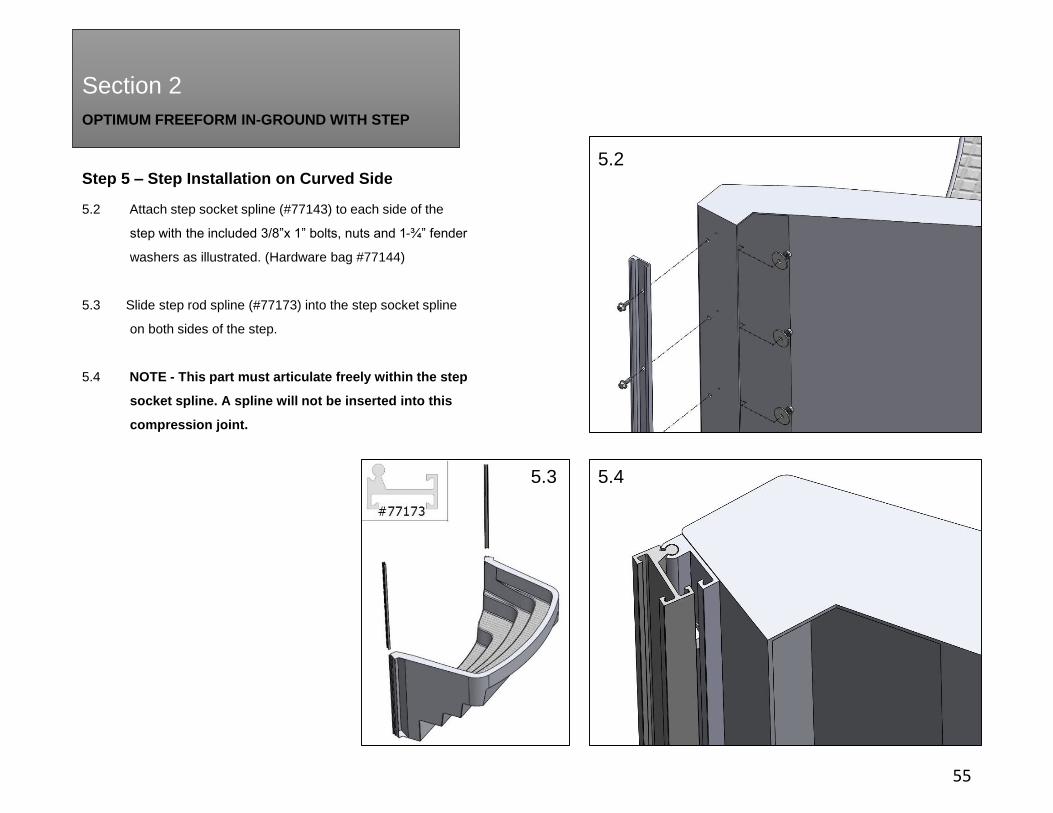
5.2 Attach step socket spline (#77143) to each side of the
step with the included 3/8”x 1” bolts, nuts and 1-¾” fender
washers as illustrated. (Hardware bag #77144)
5.3 Slide step rod spline (#77173) into the step socket spline
on both sides of the step.
5.4 NOTE - This part must articulate freely within the step
socket spline. A spline will not be inserted into this
compression joint.
5.2
5.3 5.4
OPTIMUM FREEFORM IN-GROUND WITH STEP
Section 2
Step 5 – Step Installation on Curved Side
56
5.5 5.6
x2 x2
#77148
#77146
#99-0104
#77013
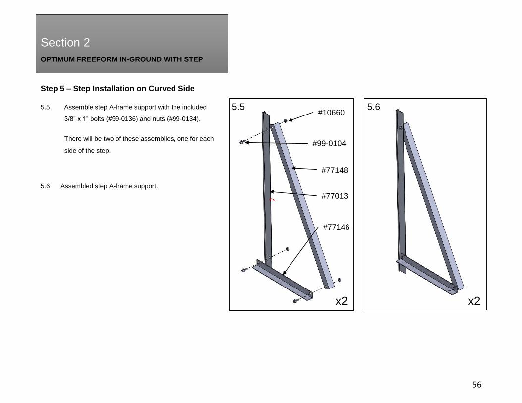
#106605.5 Assemble step A-frame support with the included
3/8” x 1” bolts (#99-0136) and nuts (#99-0134).
There will be two of these assemblies, one for each
side of the step.
5.6 Assembled step A-frame support.

OPTIMUM FREEFORM IN-GROUND WITH STEP
Section 2
Step 5 – Step Installation on Curved Side
57
5.7 Position step within the void of the pool wall making sure the
step rod splines are parallel to the ends of each filler panel. Slide a
52” spline (#77002) into the interior compression seams to lock the
step to the filler panels.
5.8 Slide one 5-¾” short spline (#77014) into the exterior compression
seams between the filler panel and step rod spline. Follow this part
with the A-frame step support previously assembled in step 5.6 and
one additional 5-¾” short spline (#77014). Once complete, there
should be three components stacked within the same joint.
Repeat for the opposing side.
5.7
4a.95.8
NO SPLINES ARE USED IN THIS JOINT
OPTIMUM FREEFORM IN-GROUND WITH STEP
Section 2
Section 2
Step 6 – Freeform Side Panel Installation
58
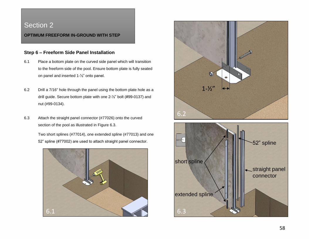
6.1 Place a bottom plate on the curved side panel which will transition
to the freeform side of the pool. Ensure bottom plate is fully seated
on panel and inserted 1-½” onto panel.
6.2 Drill a 7/16" hole through the panel using the bottom plate hole as a
drill guide. Secure bottom plate with one 2-½” bolt (#99-0137) and
nut (#99-0134).
6.3 Attach the straight panel connector (#77026) onto the curved
section of the pool as illustrated in Figure 6.3.
Two short splines (#77014), one extended spline (#77013) and one
52” spline (#77002) are used to attach straight panel connector.
6.1 6.3
6.2
1-½”
short spline
extended spline
52” spline
straight panel
connector

OPTIMUM FREEFORM IN-GROUND WITH STEP
Section 2
Section 2
Step 6 – Freeform Side Panel Installation
59
6.4 Add the first freeform section panel using two short splines
(#77014) and one extended spline (#77013).
6.5 Drill a 7/16" hole through the panel using the bottom plate
hole as a drill guide. Secure bottom plate with one 2-½” bolt
(#99-0137) and nut (#99-0134).
6.6 The freeform pool is composed of a freeform bump
section and a freeform indent section. Use Figure 6.6 to
reference where each panel should be placed within the pool.
6.4
6.5
6.6
REVERSE BUMP PANELS
INDENT PANELS
BUMP PANELS
REVERSE INDENT PANEL
OPTIMUM FREEFORM IN-GROUND WITH STEP
Section 2
Section 2
Step 6 – Freeform Side Panel Installation
60
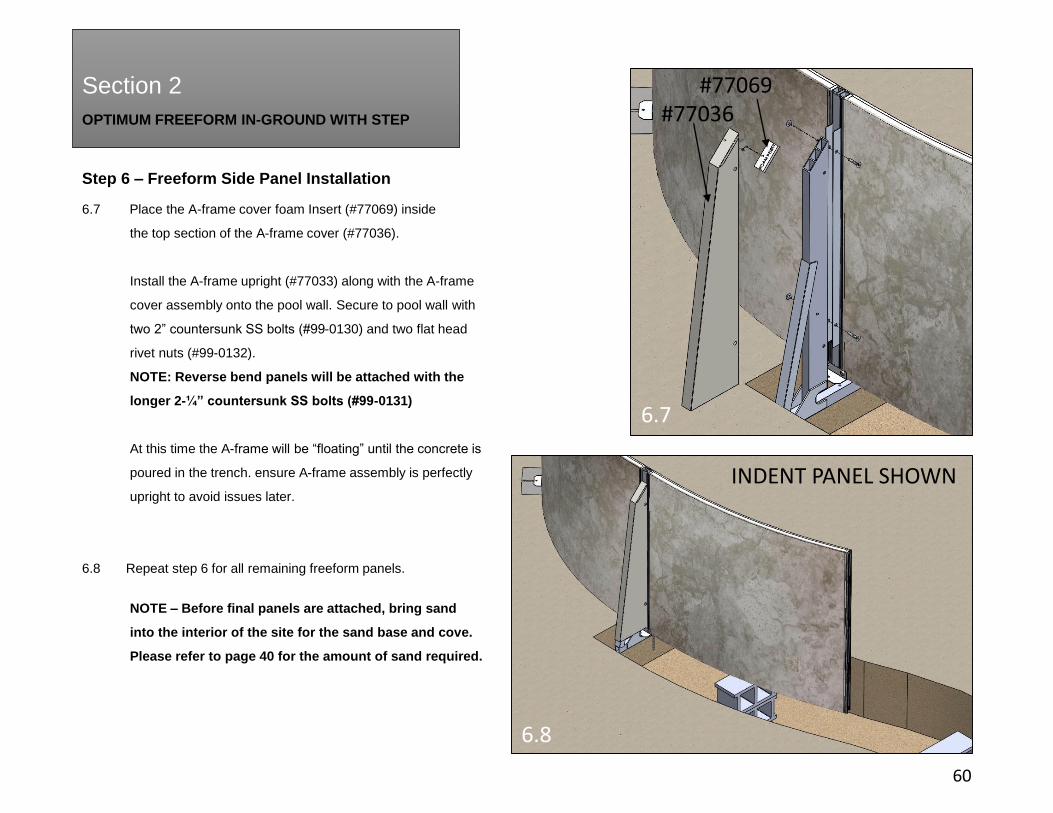
6.7 Place the A-frame cover foam Insert (#77069) inside
the top section of the A-frame cover (#77036).
Install the A-frame upright (#77033) along with the A-frame
cover assembly onto the pool wall. Secure to pool wall with
two 2” countersunk SS bolts (#99-0130) and two flat head
rivet nuts (#99-0132).
NOTE: Reverse bend panels will be attached with the
longer 2-¼” countersunk SS bolts (#99-0131)
At this time the A-frame will be “floating” until the concrete is
poured in the trench. ensure A-frame assembly is perfectly
upright to avoid issues later.
6.8 Repeat step 6 for all remaining freeform panels.
NOTE – Before final panels are attached, bring sand
into the interior of the site for the sand base and cove.
Please refer to page 40 for the amount of sand required.
6.7
6.8
INDENT PANEL SHOWN
#77069 #77036

OPTIMUM FREEFORM IN-GROUND WITH STEP
Section 2
Section 2
Step 7 – Freeform Side - Bracing
61
7.1 Install hex head 8” long bolts (#99-0141) and stainless
steel nuts (#99-0142) along with aluminum washers
(#99-0133) as illustrated onto every A-frame upright.
These bolts will be used to anchor and reinforce the A-
frame assembly into the concrete footing.

OPTIMUM FREEFORM IN-GROUND WITH STEP
Section 2
Section 2
Step 7 – Freeform Side - Bracing
62
7.2 All reverse bend panels require bracing. There will be six
brace assemblies per freeform pool. Attach the left and right
mounting brackets (#77153 & #77155) with the hardware
installed previously to attach the A-frame upright. Install one
mounting bracket at a time to keep A-frame upright assembly
attached.
NOTE: Ensure the bolts at these locations are the longer
2-¼” countersunk SS bolts (#99-0131).
7.3 Place the upper and lower freeform braces into the
mounting brackets. Once the pool is filled with water they will
be located firmly in place.
7.2
7.2.1
7.3
(#99-0131)
REVERSE PANEL
OPTIMUM FREEFORM IN-GROUND WITH STEP
Section 2
Section 2
63
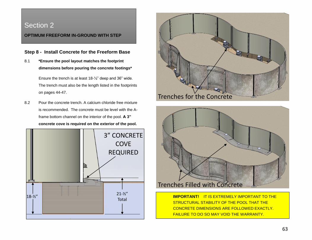
Step 8 - Install Concrete for the Freeform Base
8.1 *Ensure the pool layout matches the footprint
dimensions before pouring the concrete footings*
Ensure the trench is at least 18-½” deep and 36” wide.
The trench must also be the length listed in the footprints
on pages 44-47.
8.2 Pour the concrete trench. A calcium chloride free mixture
is recommended. The concrete must be level with the A-
frame bottom channel on the interior of the pool. A 3”
concrete cove is required on the exterior of the pool.
Trenches Filled with Concrete
Trenches for the Concrete
IMPORTANT! IT IS EXTREMELY IMPORTANT TO THE
STRUCTURAL STABILITY OF THE POOL THAT THE
CONCRETE DIMENSIONS ARE FOLLOWED EXACTLY.
FAILURE TO DO SO MAY VOID THE WARRANTY.
18-½”21-½”Total
3” CONCRETECOVE
REQUIRED

OPTIMUM FREEFORM IN-GROUND WITH STEP
Section 2
Step 9 – Concrete Collar
64
9.1 Ensure the supplied 3/8” x 15” rebar (#77001) is
inserted halfway into the ground through every bottom
plate hole around the perimeter of the pool. Also insert
two lengths of rebar through the hole on the step A-frame
support assembly from step 5.5. If extra supports are
required for patio or other pool features, consider
installing them before pouring the concrete.
Note – Ensure the pool is level and square before
pouring concrete!
9.2 A concrete collar is required on all INGROUND pools.
Pour a 8” high by 12” wide concrete collar around the
perimeter of the pool. Pour concrete foundation around
the backside of the step. See page 40 for recommended
quantities.
Note: Do not fill with water until concrete has cured.
Concrete Trench For Freeform Base
Concrete Collar
OPTIMUM FREEFORM IN-GROUND WITH STEP
Section 2
Section 2
65
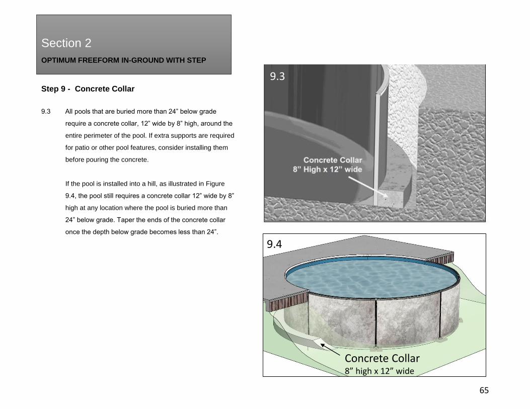
Step 9 - Concrete Collar
9.3 All pools that are buried more than 24” below grade
require a concrete collar, 12” wide by 8” high, around the
entire perimeter of the pool. If extra supports are required
for patio or other pool features, consider installing them
before pouring the concrete.
If the pool is installed into a hill, as illustrated in Figure
9.4, the pool still requires a concrete collar 12” wide by 8”
high at any location where the pool is buried more than
24” below grade. Taper the ends of the concrete collar
once the depth below grade becomes less than 24”.
Concrete Collar8” high x 12” wide
9.4
9.3

OPTIMUM FREEFORM IN-GROUND WITH STEP
Section 2
Section 2
Step 10 – Create Pool Cove and Base
66
10.1 Using neutral alkalinity sifted earth, or fine sand without
pebbles, create pool cove 4”-6” high along entire inside
perimeter of pool – THIS IS NOT AN OPTIONAL STEP
See Figure 10.1. The cove will prevent the liner from
distending beneath the pool wall under the weight of the
water.
Since chemicals that may be in the ground can cause
discoloration or corrosion, we suggest laying polyethylene
plastic sheeting under the cove around the perimeter of
the wall, ensuring that no earth comes in contact with the
metal. Since the presence of such chemicals is beyond
the control of the manufacturer, this damage is not
covered by the warranty.
DO NOT USE ANY SUBSTANCE WITH HIGH
ALKALINE OR ACID CONTENT, ESPECIALLY PEAT
MOSS, AS IT WILL CORRODE METAL PARTS.
Use remaining sand to create 2” deep sand base over the
entire pool area to protect the liner.
Rake and tamp whole area until it is level and smooth as
any bumps or ridges left will be evident under the liner.
2” SAND BASE
SAND COVE
4”– 6” COVE
10.1
10.2
OPTIMUM FREEFORM IN-GROUND WITH STEP
Section 2
Section 2
Step 11 – Skimmer Installation
67
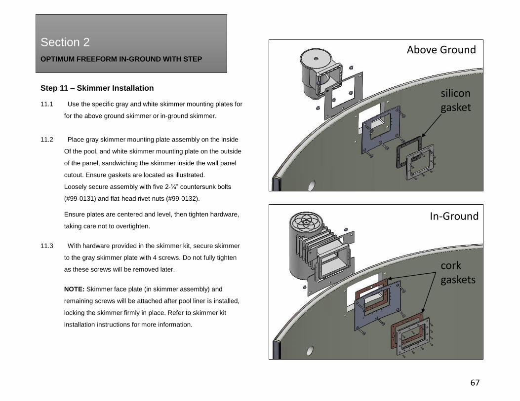
11.1 Use the specific gray and white skimmer mounting plates for
for the above ground skimmer or in-ground skimmer.
11.2 Place gray skimmer mounting plate assembly on the inside
Of the pool, and white skimmer mounting plate on the outside
of the panel, sandwiching the skimmer inside the wall panel
cutout. Ensure gaskets are located as illustrated.
Loosely secure assembly with five 2-¼” countersunk bolts
(#99-0131) and flat-head rivet nuts (#99-0132).
Ensure plates are centered and level, then tighten hardware,
taking care not to overtighten.
11.3 With hardware provided in the skimmer kit, secure skimmer
to the gray skimmer plate with 4 screws. Do not fully tighten
as these screws will be removed later.
NOTE: Skimmer face plate (in skimmer assembly) and
remaining screws will be attached after pool liner is installed,
locking the skimmer firmly in place. Refer to skimmer kit
installation instructions for more information.
Above Ground
In-Ground
cork gaskets
silicon gasket

OPTIMUM FREEFORM IN-GROUND WITH STEP
Section 2
Section 2
Step 12 – Return Fitting Installation
68
12.1 Place white return plate (#77064) over round opening
on skimmer panel and insert extended return fitting
(#77092) through assembly from interior of the pool.
Place second white return plate (#77064) over extended
return fitting on the outside of the pool.
Install extended return fitting nut to secure to panel. Do not
overtighten.
NOTE: Return fitting face plate and four screws will be
removed once pool liner is ready to be installed.
OPTIMUM FREEFORM IN-GROUND WITH STEP
Section 2
Section 2
69
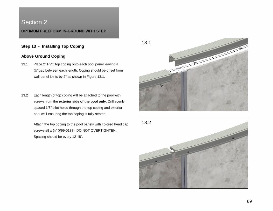
Step 13 - Installing Top Coping
Above Ground Coping
13.1 Place 2" PVC top coping onto each pool panel leaving a
½” gap between each length. Coping should be offset from
wall panel joints by 2" as shown in Figure 13.1.
13.2 Each length of top coping will be attached to the pool with
screws from the exterior side of the pool only. Drill evenly
spaced 1/8" pilot holes through the top coping and exterior
pool wall ensuring the top coping is fully seated.
Attach the top coping to the pool panels with colored head cap
screws #8 x ½” (#99-0138). DO NOT OVERTIGHTEN.
Spacing should be every 12-18”.
13.1
13.2
OPTIMUM FREEFORM IN-GROUND WITH STEP
Section 2
Section 2
70
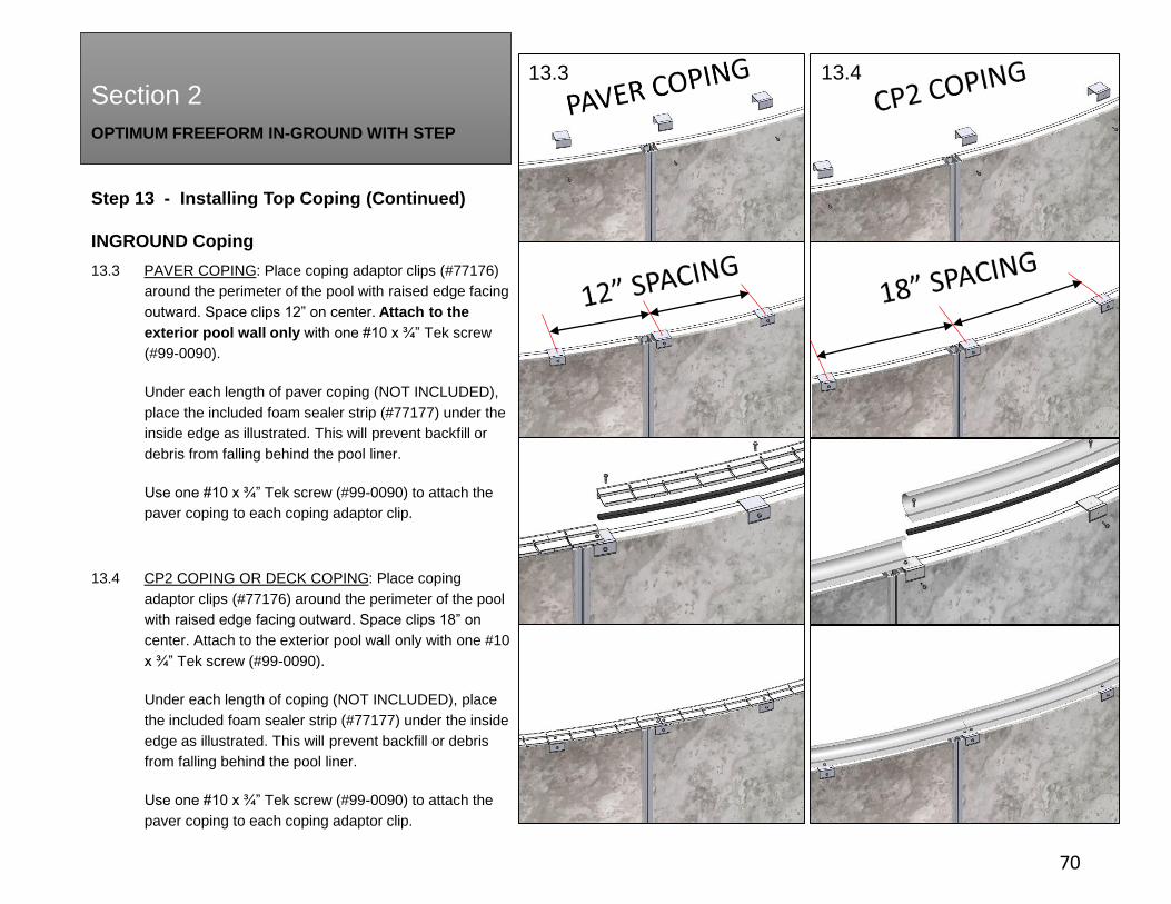
Step 13 - Installing Top Coping (Continued)
INGROUND Coping
13.3 PAVER COPING: Place coping adaptor clips (#77176)
around the perimeter of the pool with raised edge facing
outward. Space clips 12” on center. Attach to the
exterior pool wall only with one #10 x ¾” Tek screw
(#99-0090).
Under each length of paver coping (NOT INCLUDED),
place the included foam sealer strip (#77177) under the
inside edge as illustrated. This will prevent backfill or
debris from falling behind the pool liner.
Use one #10 x ¾” Tek screw (#99-0090) to attach the
paver coping to each coping adaptor clip.
13.4 CP2 COPING OR DECK COPING: Place coping
adaptor clips (#77176) around the perimeter of the pool
with raised edge facing outward. Space clips 18” on
center. Attach to the exterior pool wall only with one #10
x ¾” Tek screw (#99-0090).
Under each length of coping (NOT INCLUDED), place
the included foam sealer strip (#77177) under the inside
edge as illustrated. This will prevent backfill or debris
from falling behind the pool liner.
Use one #10 x ¾” Tek screw (#99-0090) to attach the
paver coping to each coping adaptor clip.
13.3 13.4
OPTIMUM FREEFORM IN-GROUND WITH STEP
Section 2
71
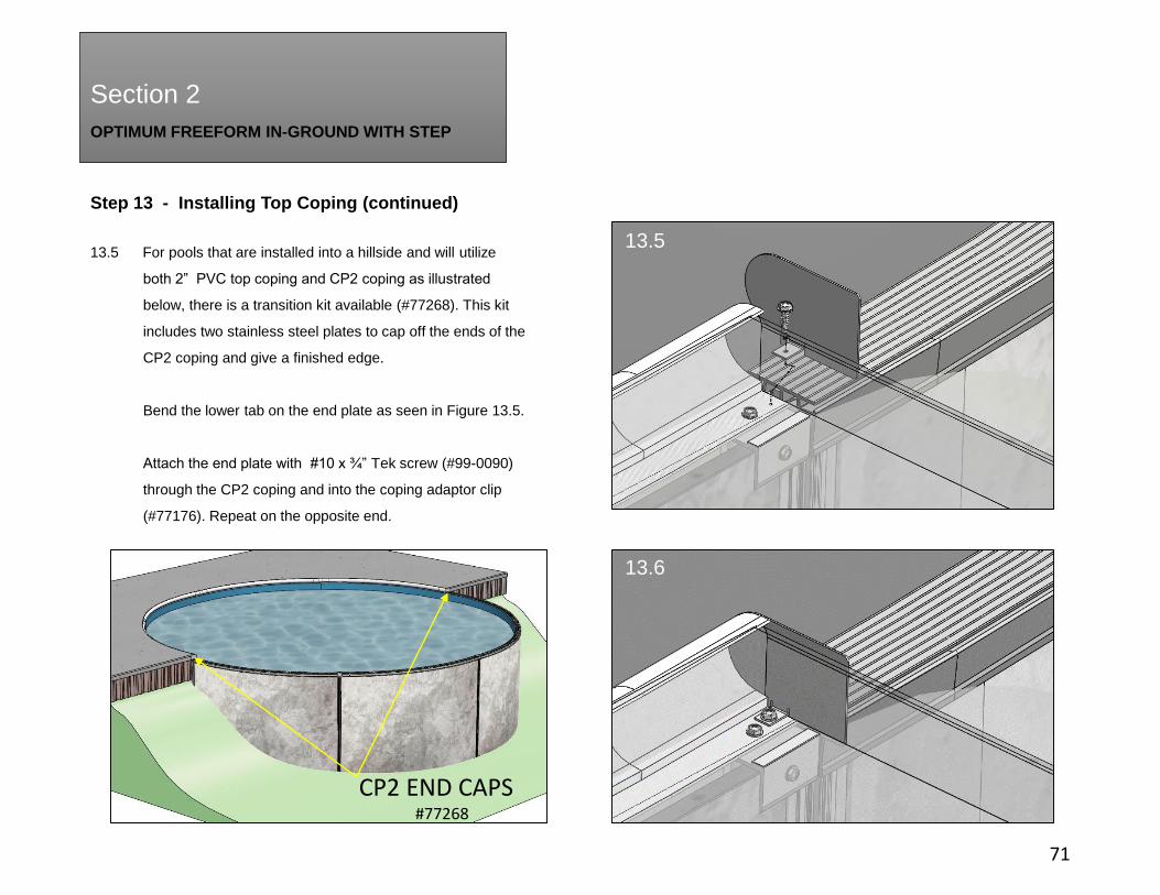
Step 13 - Installing Top Coping (continued)
13.5 For pools that are installed into a hillside and will utilize
both 2” PVC top coping and CP2 coping as illustrated
below, there is a transition kit available (#77268). This kit
includes two stainless steel plates to cap off the ends of the
CP2 coping and give a finished edge.
Bend the lower tab on the end plate as seen in Figure 13.5.
Attach the end plate with #10 x ¾” Tek screw (#99-0090)
through the CP2 coping and into the coping adaptor clip
(#77176). Repeat on the opposite end.
13.5
13.6
CP2 END CAPS#77268
OPTIMUM FREEFORM IN-GROUND WITH STEP
Section 2
Section 2
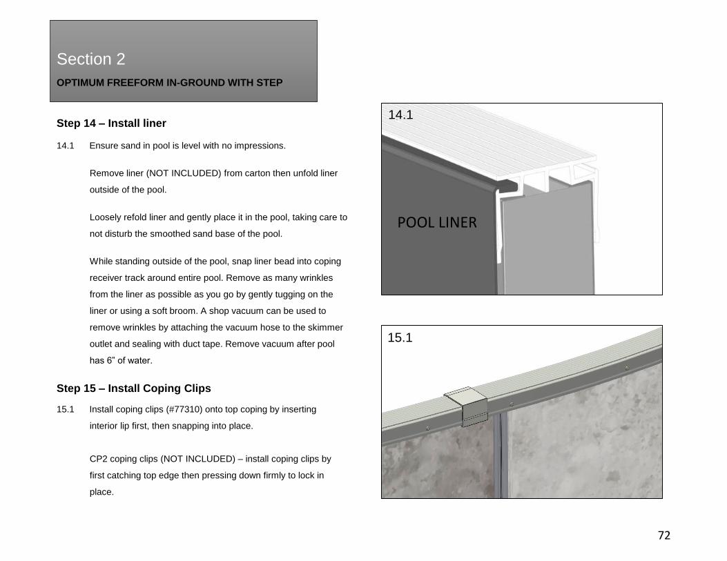
Step 14 – Install liner
72
14.1 Ensure sand in pool is level with no impressions.
Remove liner (NOT INCLUDED) from carton then unfold liner
outside of the pool.
Loosely refold liner and gently place it in the pool, taking care to
not disturb the smoothed sand base of the pool.
While standing outside of the pool, snap liner bead into coping
receiver track around entire pool. Remove as many wrinkles
from the liner as possible as you go by gently tugging on the
liner or using a soft broom. A shop vacuum can be used to
remove wrinkles by attaching the vacuum hose to the skimmer
outlet and sealing with duct tape. Remove vacuum after pool
has 6” of water.
Step 15 – Install Coping Clips
14.1
15.1
15.1 Install coping clips (#77310) onto top coping by inserting
interior lip first, then snapping into place.
CP2 coping clips (NOT INCLUDED) – install coping clips by
first catching top edge then pressing down firmly to lock in
place.
POOL LINER
OPTIMUM FREEFORM IN-GROUND WITH STEP
Section 2
Section 2
Step 16 – Add Water
73
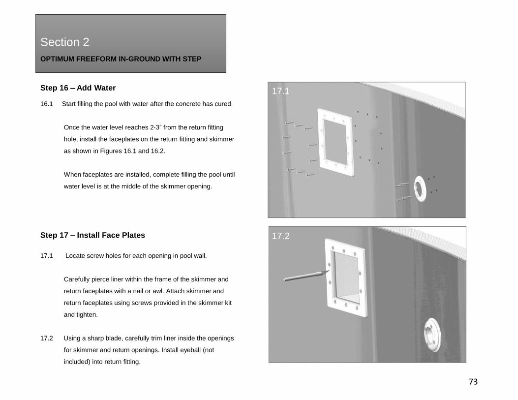
16.1 Start filling the pool with water after the concrete has cured.
Once the water level reaches 2-3” from the return fitting
hole, install the faceplates on the return fitting and skimmer
as shown in Figures 16.1 and 16.2.
When faceplates are installed, complete filling the pool until
water level is at the middle of the skimmer opening.
Step 17 – Install Face Plates
17.1 Locate screw holes for each opening in pool wall.
Carefully pierce liner within the frame of the skimmer and
return faceplates with a nail or awl. Attach skimmer and
return faceplates using screws provided in the skimmer kit
and tighten.
17.2 Using a sharp blade, carefully trim liner inside the openings
for skimmer and return openings. Install eyeball (not
included) into return fitting.
17.1
17.2
OPTIMUM FREEFORM IN-GROUND WITH STEP
Section 2
Section 2
74
Step 18 - Backfill
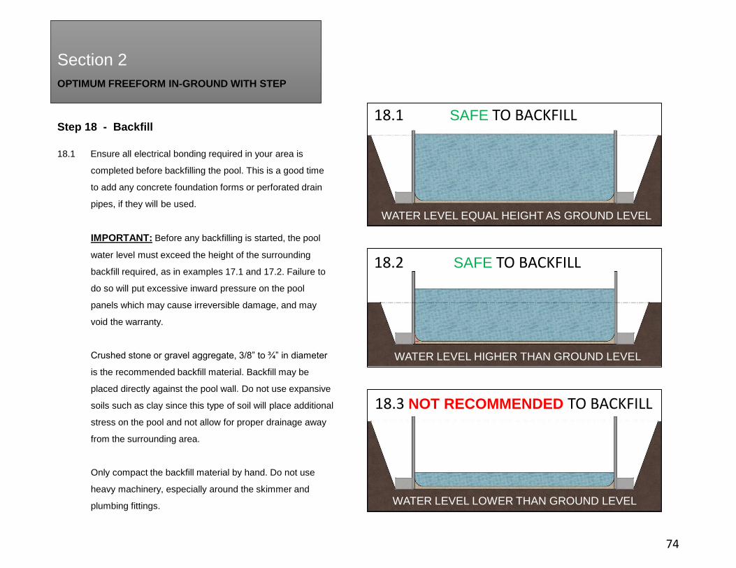
18.1 Ensure all electrical bonding required in your area is
completed before backfilling the pool. This is a good time
to add any concrete foundation forms or perforated drain
pipes, if they will be used.
IMPORTANT: Before any backfilling is started, the pool
water level must exceed the height of the surrounding
backfill required, as in examples 17.1 and 17.2. Failure to
do so will put excessive inward pressure on the pool
panels which may cause irreversible damage, and may
void the warranty.
Crushed stone or gravel aggregate, 3/8” to ¾” in diameter
is the recommended backfill material. Backfill may be
placed directly against the pool wall. Do not use expansive
soils such as clay since this type of soil will place additional
stress on the pool and not allow for proper drainage away
from the surrounding area.
Only compact the backfill material by hand. Do not use
heavy machinery, especially around the skimmer and
plumbing fittings.
18.1 SAFE TO BACKFILL
18.2 SAFE TO BACKFILL
18.3 NOT RECOMMENDED TO BACKFILL
WATER LEVEL EQUAL HEIGHT AS GROUND LEVEL
WATER LEVEL LOWER THAN GROUND LEVEL
WATER LEVEL HIGHER THAN GROUND LEVEL
75

76

77

78


![[Case Study] FreeFORM Technologies](https://img.pdfslide.us/doc/110x75/61a3ba6c56cde505261a6e2b/case-study-freeform-technologies.jpg)