Embed Size (px)
Citation preview
DOMESTIC | COMMERCIAL | INDUSTRY
OPTIMUM PERFORMANCE
IN HVAC SYSTEMS
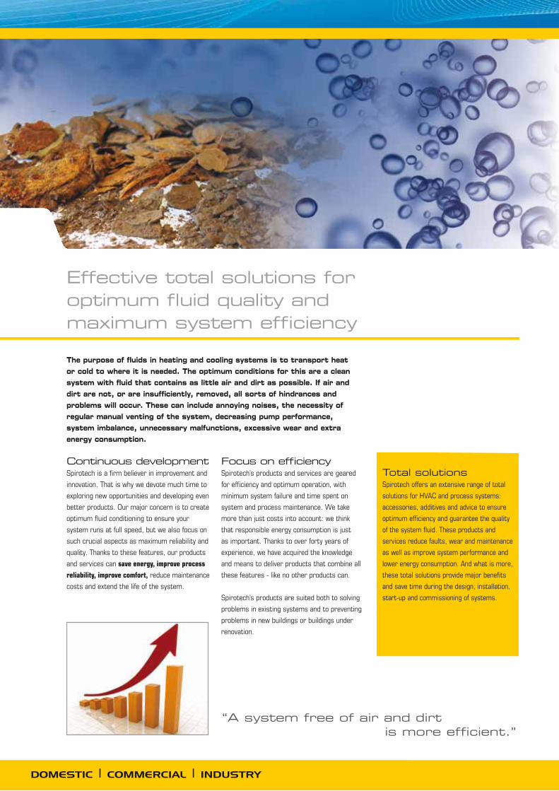
Effective total solutions for optimum fluid quality and maximum system efficiency
“A system free of air and dirt is more efficient.”
DOMESTIC | COMMERCIAL | INDUSTRY
The purpose of fluids in heating and cooling systems is to transport heat or cold to where it is needed. The optimum conditions for this are a clean system with fluid that contains as little air and dirt as possible. If air and dirt are not, or are insufficiently, removed, all sorts of hindrances and problems will occur. These can include annoying noises, the necessity of regular manual venting of the system, decreasing pump performance, system imbalance, unnecessary malfunctions, excessive wear and extra energy consumption.
Continuous developmentSpirotech is a firm believer in improvement and
innovation. That is why we devote much time to
exploring new opportunities and developing even
better products. Our major concern is to create
optimum fluid conditioning to ensure your
system runs at full speed, but we also focus on
such crucial aspects as maximum reliability and
quality. Thanks to these features, our products
and services can save energy, improve process
reliability, improve comfort, reduce maintenance
costs and extend the life of the system.
Focus on efficiencySpirotech’s products and services are geared
for efficiency and optimum operation, with
minimum system failure and time spent on
system and process maintenance. We take
more than just costs into account: we think
that responsible energy consumption is just
as important. Thanks to over forty years of
experience, we have acquired the knowledge
and means to deliver products that combine all
these features - like no other products can.
Spirotech’s products are suited both to solving
problems in existing systems and to preventing
problems in new buildings or buildings under
renovation.
Total solutionsSpirotech offers an extensive range of total
solutions for HVAC and process systems:
accessories, additives and advice to ensure
optimum efficiency and guarantee the quality
of the system fluid. These products and
services reduce faults, wear and maintenance
as well as improve system performance and
lower energy consumption. And what is more,
these total solutions provide major benefits
and save time during the design, installation,
start-up and commissioning of systems.
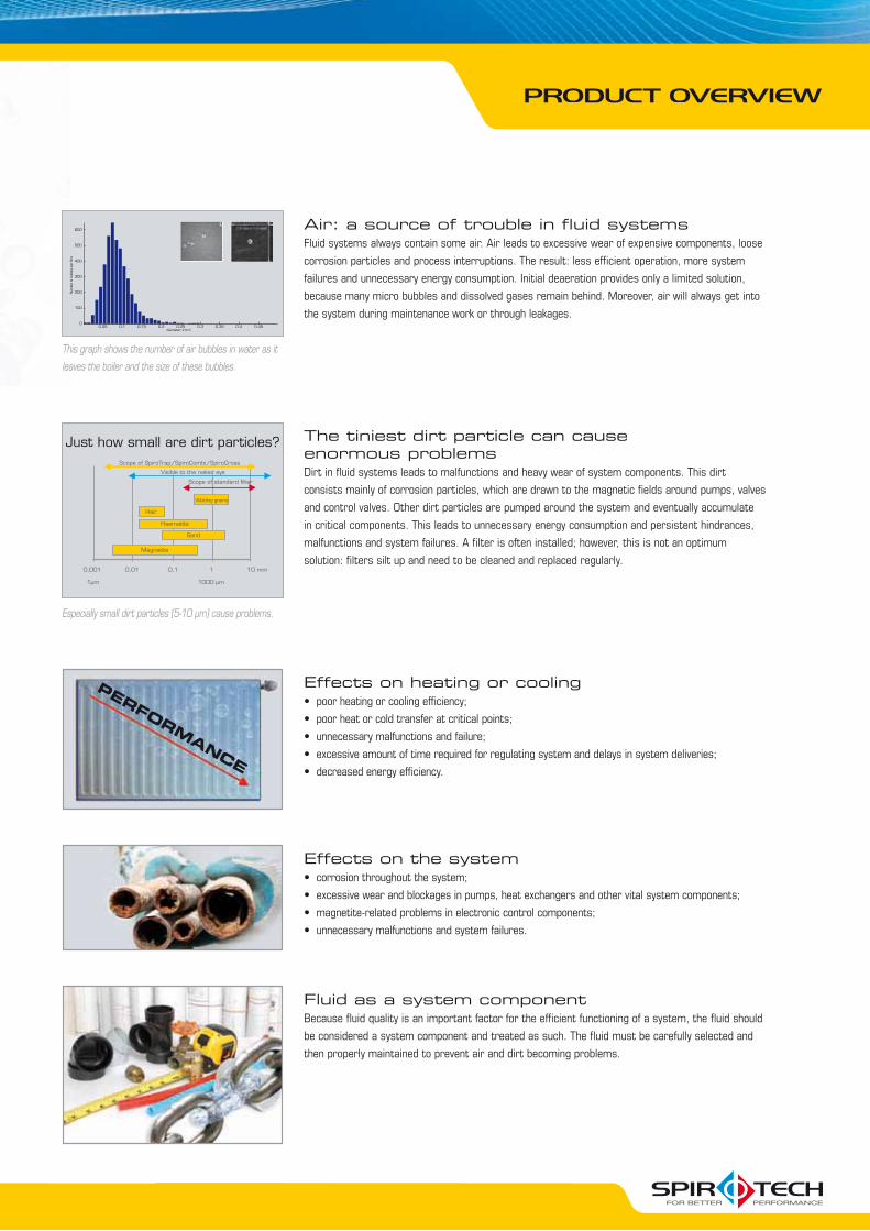
The tiniest dirt particle can cause enormous problemsDirt in fluid systems leads to malfunctions and heavy wear of system components. This dirt
consists mainly of corrosion particles, which are drawn to the magnetic fields around pumps, valves
and control valves. Other dirt particles are pumped around the system and eventually accumulate
in critical components. This leads to unnecessary energy consumption and persistent hindrances,
malfunctions and system failures. A filter is often installed; however, this is not an optimum
solution: filters silt up and need to be cleaned and replaced regularly.
Just how small are dirt particles?
0,001
1μm 1000 μm
0,01 0,1
Visible to the naked eye
1 10 mm
Scope of standard filter
Welding grains
Hair
Haematite
Sand
Magnetite
Scope of SpiroTrap/SpiroCombi/SpiroCross
Especially small dirt particles (5-10 μm) cause problems.
600
500
400
300
200
100
00.05 0.1 0.15 0.2 0.25 0.3 0.35 0.4 0.45
diameter [mm]
Num
ber
of b
ubbl
es p
er li
tre
This graph shows the number of air bubbles in water as it
leaves the boiler and the size of these bubbles.
Effects on heating or cooling
Effects on the system
Fluid as a system componentBecause fluid quality is an important factor for the efficient functioning of a system, the fluid should
be considered a system component and treated as such. The fluid must be carefully selected and
then properly maintained to prevent air and dirt becoming problems.
Air: a source of trouble in fluid systemsFluid systems always contain some air. Air leads to excessive wear of expensive components, loose
corrosion particles and process interruptions. The result: less efficient operation, more system
failures and unnecessary energy consumption. Initial deaeration provides only a limited solution,
because many micro bubbles and dissolved gases remain behind. Moreover, air will always get into
the system during maintenance work or through leakages.
PERFORMANCE
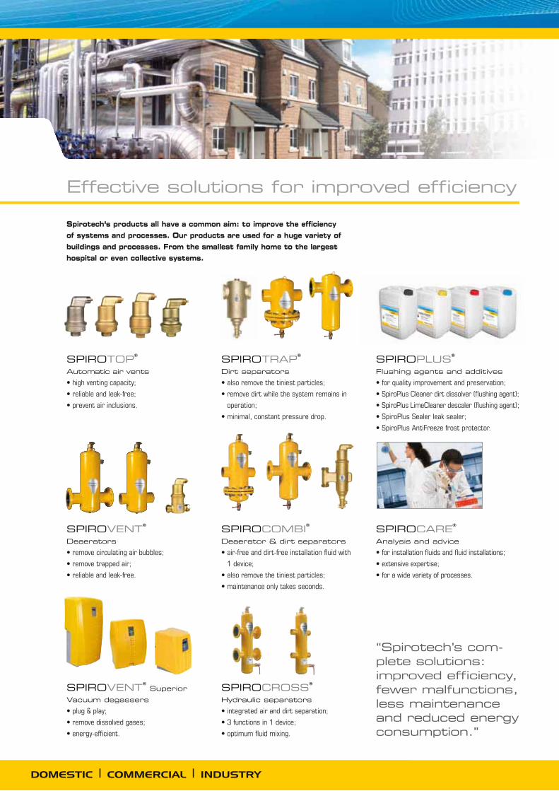
SPIROTOP
Automatic air vents
SPIROVENTDeaerators
SPIROVENT Superior
Vacuum degassers
SPIROTRAP
Dirt separators
operation;
SPIROCOMBI
Deaerator & dirt separators
1 device;
SPIROCROSS
Hydraulic separators
SPIROPLUS
Flushing agents and additives
SPIROCARE
Analysis and advice
DOMESTIC | COMMERCIAL | INDUSTRY
Effective solutions for improved efficiency
Spirotech’s products all have a common aim: to improve the efficiency of systems and processes. Our products are used for a huge variety of buildings and processes. From the smallest family home to the largest hospital or even collective systems.
“Spirotech’s com-plete solutions: improved efficiency, fewer malfunctions, less maintenance and reduced energy consumption.”
112
52
Ø65
RH
d
1
2
3
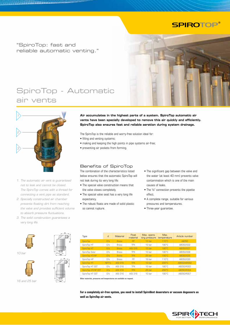
1. The automatic air vent is guaranteed
not to leak and cannot be closed.
The SpiroTop comes with a thread for
connecting a vent pipe as standard.
2. Specially constructed air chamber
prevents floating dirt from reaching
the valve and provides sufficient volume
to absorb pressure fluctuations.
3. The solid construction guarantees a
very long life.
Air accumulates in the highest parts of a system. SpiroTop automatic air vents have been specially developed to remove this air quickly and efficiently. SpiroTop also ensures fast and reliable aeration during system drainage.
The SpiroTop is the reliable and worry-free solution ideal for:
“SpiroTop: fast and reliable automatic venting.”
Benefits of SpiroTopThe combination of the characteristics listed
below ensures that the automatic SpiroTop will
not leak during its very long life:
the valve closes completely.
expectancy.
so cannot rupture.
the water (at least 40 mm) prevents valve
contamination which is one of the main
causes of leaks.
effect.
pressures and temperatures.
For a completely air-free system, you need to install SpiroVent deaerators or vacuum degassers as
well as SpiroTop air vents.
16 and 25 bar
10 bar
SpiroTop - Automatic air vents
Type d Material Float material
Max. opera-ting pressure
Max. temperature Article number
SpiroTop Brass PP 10 bar 110°C AB050
SpiroTop HT Brass TPX 10 bar 180°C AB050/002
SpiroTop HT Brass AISI 316 10 bar 180°C AB050/007
SpiroTop Solar Brass TPX 10 bar 180°C AB050/008
SpiroTop HT/HP Brass TPX 25 bar 150°C AB050/025
SpiroTop HP Brass PP 16 bar 110°C AB050/030
SpiroTop HT AISI 316 TPX 10 bar 200°C AB050/AR002
SpiroTop HT SST AISI 316 TPX 10 bar 180°C AB050/R002
SpiroTop HT/HP SST AISI 316 TPX 25 bar 200°C AB050/R004
SpiroTop HT SST AISI 316 AISI 316 10 bar 180°C AB050/R007
Other materials, pressures and temperatures are available on request.
1
2
3
4
5
6
7
8
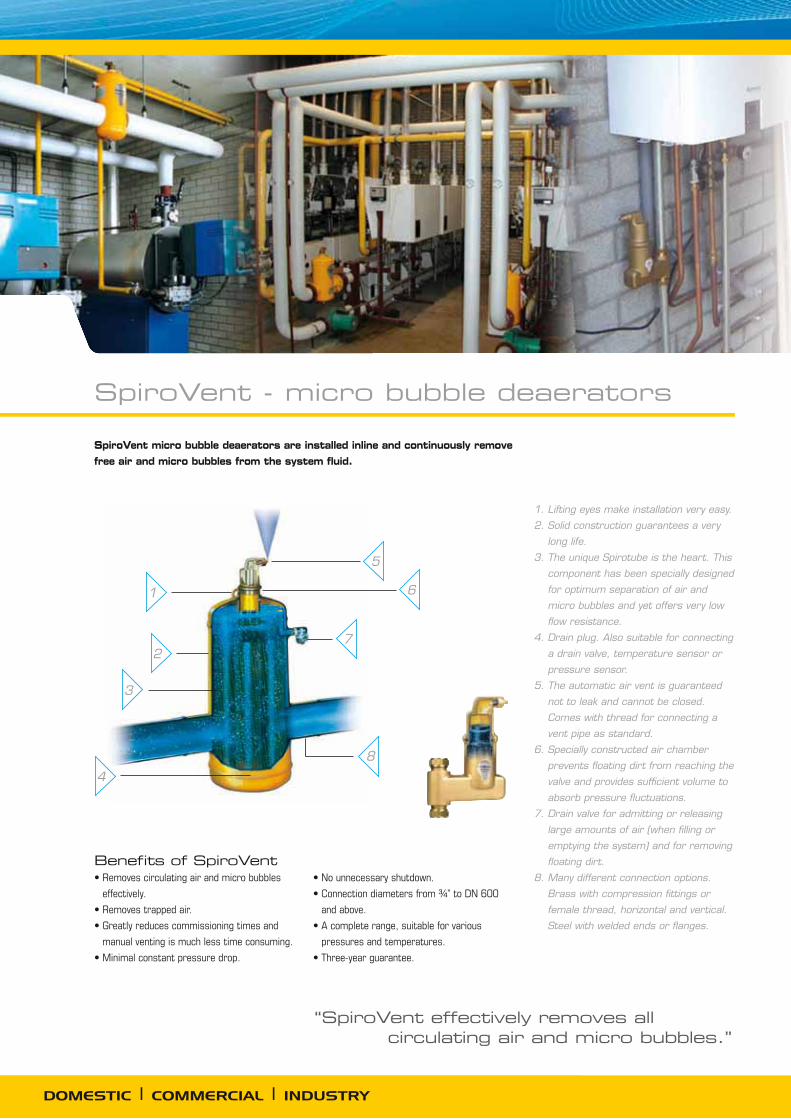
1. Lifting eyes make installation very easy.
2. Solid construction guarantees a very
long life.
3. The unique Spirotube is the heart. This
component has been specially designed
for optimum separation of air and
micro bubbles and yet offers very low
flow resistance.
4. Drain plug. Also suitable for connecting
a drain valve, temperature sensor or
pressure sensor.
5. The automatic air vent is guaranteed
not to leak and cannot be closed.
Comes with thread for connecting a
vent pipe as standard.
6. Specially constructed air chamber
prevents floating dirt from reaching the
valve and provides sufficient volume to
absorb pressure fluctuations.
7. Drain valve for admitting or releasing
large amounts of air (when filling or
emptying the system) and for removing
floating dirt.
8. Many different connection options.
Brass with compression fittings or
female thread, horizontal and vertical.
Steel with welded ends or flanges.
“SpiroVent effectively removes all circulating air and micro bubbles.”
DOMESTIC | COMMERCIAL | INDUSTRY
SpiroVent micro bubble deaerators are installed inline and continuously remove free air and micro bubbles from the system fluid.
Benefits of SpiroVent
effectively.
manual venting is much less time consuming.
and above.
pressures and temperatures.
SpiroVent - micro bubble deaerators

Max. flow m3/h and l/s Applicable SpiroVent
m3/h
12.5
20
25
27
40
47
54
72
94
108
144
180
215
288
360
405
500
575
650
810
850
1000
1060
1300
1530
1700
2120
3000 Standard
Hi-flow
3.5
5.5 7 7.5
11
13
15
20
26
30
40
50
60
80
100
113
140
160
180
225
235
280
295
360
425
470
590
835
DN050 BA050 HA050
DN065 BA065 HA065
DN080 BA080 HA080
DN100 BA100 HA100
DN125 BA125 HA125
DN150 BA150 HA150
DN200 BA200 HA200
DN250 BA250 HA250
DN300 BA300 HA300
DN350 BA350 HA350
DN400 BA400 HA400
DN450 BA450 HA450
DN500 BA500 HA500
DN600 BA600 HA600
= standard type; max. 1.5 m/s = Hi-fl ow type recommended; max. 3 m/s = choose bigger Ø or lower the flow
l/s∅
Other sizes, materials, pressures and temperatures are available on request.
Select the correct SpiroVent:1. Determine the pipe diameter.
2. Determine the flow.
3. Determine the correct model using the table.
A SpiroVent deaerator is
preferably to be installed
at the hottest point within
a system. In the case of a
heating system, for example,
this is the point where the
water exits the boiler. In the
case of a cooling system,
it is in the return before
the chiller unit.
Standard: DN50 to DN600
Hi-flow: DN50 to DN600
Standard type (1.5 m/s) Hi-flow type (3 m/s)
Connection [D
N]
Connection O
D [m
m]
L (mm
)
LF (mm
)
H (m
m)
Max. flow
[l/s]
Max. flow
[m3/
h]
p at max. flow
[kPa]
Article num
ber
H (m
m)
Max. flow
[l/s]
Max. flow
[m3/
h]
p at max. flow
[kPa]
Article num
ber
050 60.3 260 350 470 3.5 12.5 3.0 BA050 630 7 25 11.8 HA050
065 76.1 260 350 470 5.5 20 2.7 BA065 630 11 40 11.6 HA065
080 88.9 370 470 590 7.5 27 2.9 BA080 785 15 54 12.4 HA080
100 114.3 370 475 590 13 47 3.7 BA100 785 26 94 14.6 HA100
125 139.7 525 635 765 20 72 4.2 BA125 1045 40 144 16.8 HA125
150 168.3 525 635 765 30 108 4.9 BA150 1045 60 215 19.4 HA150
200 219.1 650 775 975 50 180 5.8 BA200 1315 100 360 23.1 HA200
250 273.0 750 890 1215 80 288 6.9 BA250 1715 160 575 27.7 HA250
300 323.9 850 1005 1430 113 405 7.7 BA300 2025 225 810 31.0 HA300
350 356 NA 1100 1910 140 500 7.8 BA350 2400 280 1000 31.0 HA350
400 406 NA 1200 2120 180 650 8.4 BA400 2680 360 1300 34.0 HA400
450 457 NA 1300 2320 235 850 10.0 BA450 2960 470 1700 39.0 HA450
500 508 NA 1400 2540 295 1060 11.0 BA500 3250 590 2120 43.0 HA500
600 610 NA 1600 2980 425 1530 12.0 BA600 3830 835 3000 47.0 HA600
Operating pressure: 0 - 10 bar Fluid temperature 0 - 110 °C
Other sizes, materials, pressures and temperatures are available on request.
Standard
Hi-flow
Brass, horizontal: 22 mm up to 2”
Brass, vertical: 22 mm up to 1”
Connection
H (mm)
L (mm)
Max. flow [m3/h]
Max. flow [l/s]
p at max. flow [kPa]
Article number
22 mm. comp. 153 106 1.3 0.35 1.3 AA022
22 mm. comp.V 220 104 1.3 0.35 1.5 AA022V
153 85 1.3 0.35 1.3 AA075
210 84 1.3 0.35 1.5 AA075V
G1 180 88 2.0 0.55 1.3 AA100
G1V 210 84 2.0 0.55 2.4 AA100V
G1¼ 200 88 3.6 1.0 1.3 AA125
234 88 5.0 1.4 1.3 AA150
G2 275 132 7.5 2.1 1.4 AA200
V = Vertical connection Flow velocity ≤ 1 m/s
Operating pressure: 0 - 10 bar Fluid temperature 0 - 110 °C
Other sizes, materials, pressures and temperatures are available on request

SpiroVent Superior - vacuum degassers
The SpiroVent Superior is a fully automatic vacuum degasser for heating, cooling and process systems. Because of the fully electronic control system, the Superior offers numerous facilities for reading system information, status and logged data.
When should a vacuum degasser be used?1. For systems with many branches and a low flow velocity.
2. When there are slight temperature differences. A vacuum degasser is not dependent on
the fluid temperature.
3. When an inline degasser cannot be mounted due to practical reasons. A vacuum degasser
can be connected to virtually any point within a system.
Benefits of SpiroVent Superior
trapped gas bubbles.
pump systems and underfloor heating systems.
expansion systems.
S10, for heating or cooling systems from
5 to 10 bar, up to 300 m3
S16, for heating or cooling systems from
9 to 16 bar, up to 300 m3
S3, for heating or cooling systems up to
3.5 bar, up to 15 m3
S6, for heating or cooling systems up to
6 bar, up to 300 m3
How the SpiroVent Superior worksA continuously operating pump constantly takes a quantity of system fluid from the circulating
flow. Closing a solenoid valve creates a vacuum so that the dissolved gases are released.
These accumulate at the top of the vessel and are removed via the air vent. The degassed and
absorptive fluid is then pumped back into the installation and can start absorbing gases again.
There are various reasons why gas will always be able to enter a system, such as diffusion,
micro leaks and expansion system membranes which are never 100% gastight. Because of all this,
vacuum degassing is a continuous requirement. It is therefore not a one-off process.
DOMESTIC | COMMERCIAL | INDUSTRY
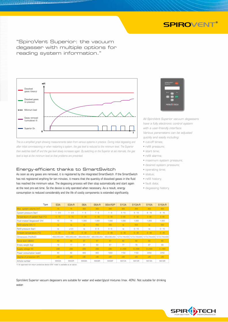
ml/l
T
Dissolved gases (theory)
Dissolved gases (in practice)
Minimum level
Gases removed (cumulative) (l)
Superior On0
SpiroVent Superior vacuum degassers are suitable for water and water/glycol mixtures (max. 40%). Not suitable for drinking
water.
S3A S3A-R S6A S6A-R S6A-R2P S10A S10A-R S16A S16A-R
Max. system volume [m3] 15 15 300 300 300 300 300 300 300
System pressure [bar] 1 - 3.5 1 - 3.5 1 - 6 1 - 6 1 - 6 5 -10 5 - 10 9 - 16 9 - 16
Temperature of system fluid [°C] 0 - 70 0 - 70 0 - 90 0 - 90 0 - 90 0 -90 0 - 90 0 -90 0 -90
Fluid treated (degassed) [l/h] 70 70 1,000 1,000 1,000 1,000 1,000 1,000 1,000
Refill volume [l/h] 1) na na na 450 450 na 500 na 500
Refill pressure [bar] na ≥ 0,5 na 0 - 6 0 - 6 na 0 - 10 na 0 - 10
Ambient temperature [°C] 0 - 50 0 - 50 0 - 40 0 - 40 0 - 40 0 - 40 0 - 40 0 - 40 0 - 40
Dimensions [HxWxD] 490x340x340 490x340x340 880x590x350 880x590x350 880x590x350 1272x744x400 1272x744x400 1272x744x400 1272x744x400
Noise level [dB(A)] 49 49 57 57 57 60 60 60 60
Empty weight [kg] 16 17 57 59 67 77 79 87 89
Supply voltage [V] 230 230 230 230 230 3 x 400 3 x 400 3 x 400 3 x 400
Power consumption [watt] 40 40 800 800 1300 1150 1150 2250 2250
Degree of protection [IP] x4D x4D x4D x4D x4D x4D x4D x4D x4D
Article number MA03A MA03R MA06A MA06R MA06P MA10A MA10R MA16A MA16R
Type
This is a simplified graph showing measurements taken from various systems in practice. During initial degassing and
after initial commissioning or when restarting a system, the gas level is reduced to the minimum level. The Superior
then switches itself off and the gas level slowly increases again. By switching on the Superior at set intervals, the gas
level is kept at the minimum level so that problems are prevented.
Energy-efficient thanks to SmartSwitchAs soon as any gases are removed, it is registered by the integrated SmartSwitch. If the SmartSwitch
has not registered anything for ten minutes, it means that the quantity of dissolved gases in the fluid
has reached the minimum value. The degassing process will then stop automatically and start again
at the next pre-set time. So the device is only operated when necessary. As a result, energy
consumption is reduced considerably and the life of costly components is extended significantly.
“SpiroVent Superior: the vacuum degasser with multiple options for reading system information.”
All SpiroVent Superior vacuum degassers
have a fully electronic control system
with a user-friendly interface.
Various parameters can be adjusted
quickly and easily including:
1
2
3
4
7
6
5
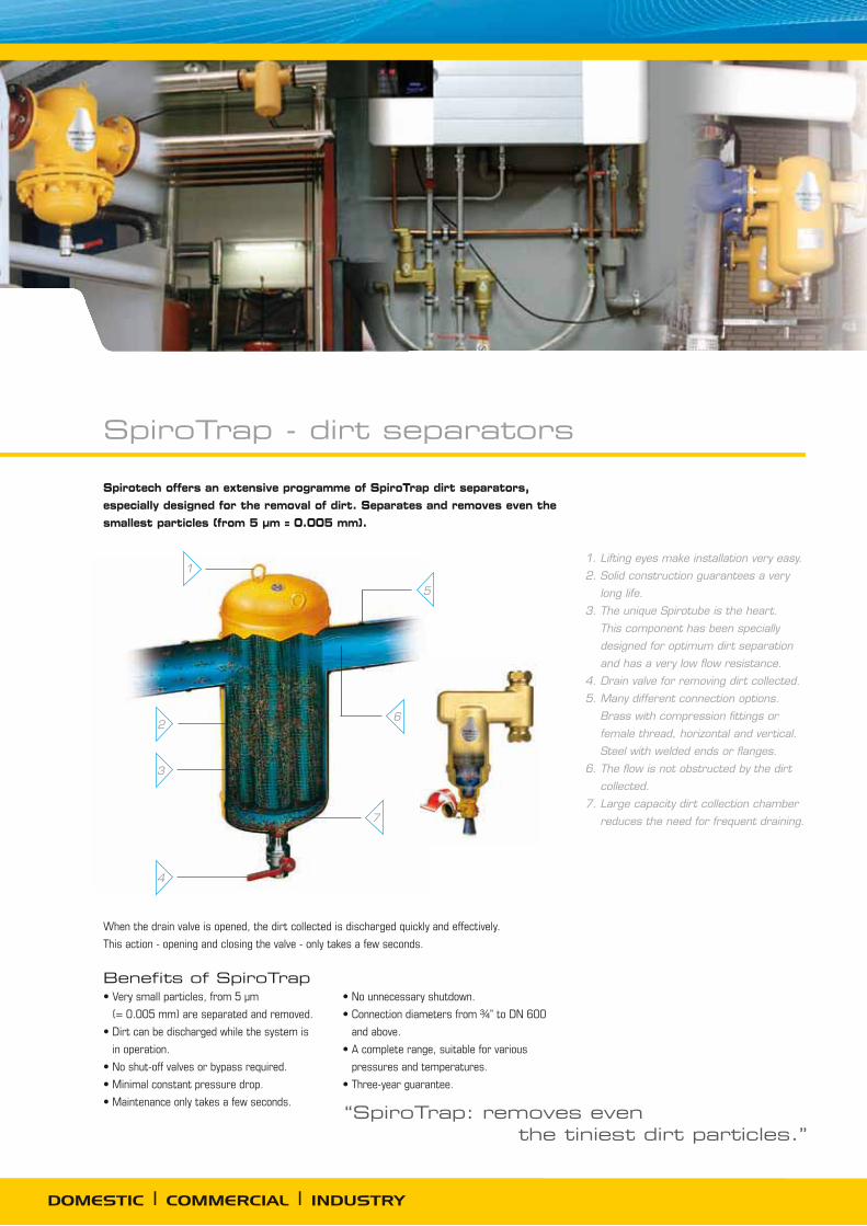
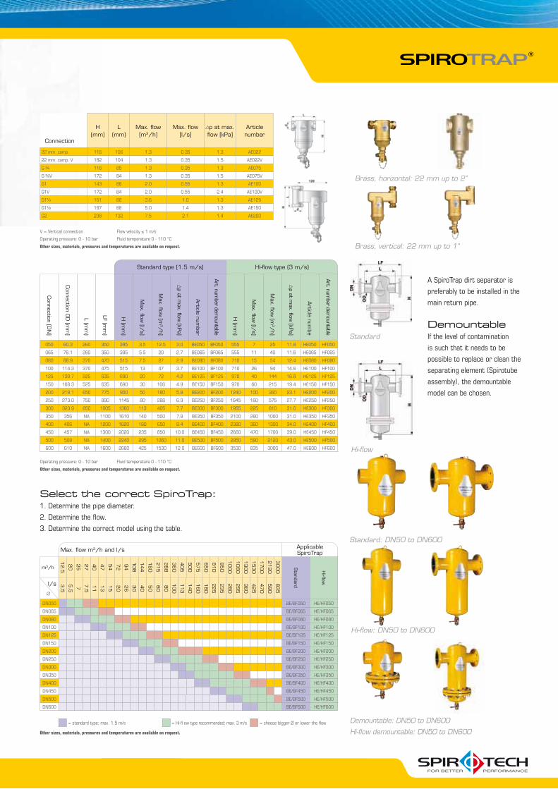
Spirotech offers an extensive programme of SpiroTrap dirt separators, especially designed for the removal of dirt. Separates and removes even the smallest particles (from 5 μm = 0.005 mm).
Benefits of SpiroTrap
(= 0.005 mm) are separated and removed.
in operation.
and above.
pressures and temperatures.
“SpiroTrap: removes even the tiniest dirt particles.”
DOMESTIC | COMMERCIAL | INDUSTRY
When the drain valve is opened, the dirt collected is discharged quickly and effectively.
This action - opening and closing the valve - only takes a few seconds.
1. Lifting eyes make installation very easy.
2. Solid construction guarantees a very
long life.
3. The unique Spirotube is the heart.
This component has been specially
designed for optimum dirt separation
and has a very low flow resistance.
4. Drain valve for removing dirt collected.
5. Many different connection options.
Brass with compression fittings or
female thread, horizontal and vertical.
Steel with welded ends or flanges.
6. The flow is not obstructed by the dirt
collected.
7. Large capacity dirt collection chamber
reduces the need for frequent draining.
SpiroTrap - dirt separators
Max. flow m3/h and l/s Applicable SpiroTrap
m3/h
12.5
20
25
27
40
47
54
72
94
108
144
180
215
288
360
405
500
575
650
810
850
1000
1060
1300
1530
1700
2120
3000 Standard
Hi-flow
3.5
5.5 7 7.5
11
13
15
20
26
30
40
50
60
80
100
113
140
160
180
225
235
280
295
360
425
470
590
835
DN050 BE/BF050 HE/HF050
DN065 BE/BF065 HE/HF065
DN080 BE/BF080 HE/HF080
DN100 BE/BF100 HE/HF100
DN125 BE/BF125 HE/HF125
DN150 BE/BF150 HE/HF150
DN200 BE/BF200 HE/HF200
DN250 BE/BF250 HE/HF250
DN300 BE/BF300 HE/HF300
DN350 BE/BF350 HE/HF350
DN400 BE/BF400 HE/HF400
DN450 BE/BF450 HE/HF450
DN500 BE/BF500 HE/HF500
DN600 BE/BF600 HE/HF600
= standard type; max. 1.5 m/s = Hi-fl ow type recommended; max. 3 m/s = choose bigger Ø or lower the flow Demountable: DN50 to DN600
Hi-flow demountable: DN50 to DN600
Standard: DN50 to DN600
Hi-flow: DN50 to DN600
Standard
Hi-flow
A SpiroTrap dirt separator is
preferably to be installed in the
main return pipe.
DemountableIf the level of contamination
is such that it needs to be
possible to replace or clean the
separating element (Spirotube
assembly), the demountable
model can be chosen.
Standard type (1.5 m/s) Hi-flow type (3 m/s)
Connection [D
N]
Connection O
D [m
m]
L (mm
)
LF (mm
)
H (m
m)
Max. flow
[l/s]
Max. flow
[m3/
h]
p at max. flow
[kPa]
Article num
ber
Art. num
ber demountable
H (m
m)
Max. flow
[l/s]
Max. flow
[m3/
h]
p at max. flow
[kPa]
Article num
be
Art. num
ber demountable
050 60.3 260 350 395 3.5 12.5 3.0 BE050 BF050 555 7 25 11.8 HE050 HF050
065 76.1 260 350 395 5.5 20 2.7 BE065 BF065 555 11 40 11.6 HE065 HF065
080 88.9 370 470 515 7.5 27 2.9 BE080 BF080 710 15 54 12.4 HE080 HF080
100 114.3 370 475 515 13 47 3.7 BE100 BF100 710 26 94 14.6 HE100 HF100
125 139.7 525 635 690 20 72 4.2 BE125 BF125 970 40 144 16.8 HE125 HF125
150 168.3 525 635 690 30 108 4.9 BE150 BF150 970 60 215 19.4 HE150 HF150
200 219.1 650 775 900 50 180 5.8 BE200 BF200 1240 100 360 23.1 HE200 HF200
250 273.0 750 890 1145 80 288 6.9 BE250 BF250 1645 160 575 27.7 HE250 HF250
300 323.9 850 1005 1360 113 405 7.7 BE300 BF300 1955 225 810 31.0 HE300 HF300
350 356 NA 1100 1610 140 500 7.8 BE350 BF350 2100 280 1000 31.0 HE350 HF350
400 406 NA 1200 1820 180 650 8.4 BE400 BF400 2380 360 1300 34.0 HE400 HF400
450 457 NA 1300 2020 235 850 10.0 BE450 BF450 2660 470 1700 39.0 HE450 HF450
500 508 NA 1400 2240 295 1060 11.0 BE500 BF500 2950 590 2120 43.0 HE500 HF500
600 610 NA 1600 2680 425 1530 12.0 BE600 BF600 3530 835 3000 47.0 HE600 HF600
Operating pressure: 0 - 10 bar Fluid temperature 0 - 110 °C
Other sizes, materials, pressures and temperatures are available on request.
Select the correct SpiroTrap:1. Determine the pipe diameter.
2. Determine the flow.
3. Determine the correct model using the table.
Other sizes, materials, pressures and temperatures are available on request.
l/s
Connection
H (mm)
L(mm)
Max. flow [m3/h]
Max. flow [l/s]
p at max. flow [kPa]
Article number
22 mm. comp. 116 106 1.3 0.35 1.3 AE022
22 mm. comp. V 182 104 1.3 0.35 1.5 AE022V
116 85 1.3 0.35 1.3 AE075
172 84 1.3 0.35 1.5 AE075V
G1 143 88 2.0 0.55 1.3 AE100
G1V 172 84 2.0 0.55 2.4 AE100V
G1¼ 161 88 3.6 1.0 1.3 AE125
197 88 5.0 1.4 1.3 AE150
G2 238 132 7.5 2.1 1.4 AE200
Brass, vertical: 22 mm up to 1”
Brass, horizontal: 22 mm up to 2”
V = Vertical connection Flow velocity ≤ 1 m/s
Operating pressure: 0 - 10 bar Fluid temperature 0 - 110 °C
Other sizes, materials, pressures and temperatures are available on request.
∅

2
8
1
3
4
7
9
6
5
10
Spirotech offers an extensive programme of SpiroCombi deaerators/dirt separators, especially designed for the simultaneous removal of air and dirt. These remove air, micro bubbles and dirt particles from the system water continuously.
SpiroCombi deaerators and dirt separators
“SpiroCombi: continuous removal of air and dirt.”
DOMESTIC | COMMERCIAL | INDUSTRY
Benefits of SpiroCombi
effectively.
(= 0.005 mm), are separated and removed.
operation.
and above.
pressures and temperatures.
When the drain valve is opened, the dirt collected is discharged quickly and effectively.
This action - opening and closing the valve - only takes a few seconds.
1. The automatic air vent is guaranteed
not to leak and cannot be closed.
Comes with thread for connecting a
vent pipe as standard.
2. Lifting eyes make installation
very easy.
3. Specially constructed air chamber
prevents floating dirt from reaching
the valve and provides sufficient
volume to absorb pressure
fluctuations.
4. Drain valve for admitting or releasing
large amounts of air (when filling
or emptying the system) and for
removing floating dirt.
5. Many different connection options.
Brass with compression fittings
or female thread, horizontal and
vertical. Steel with welded ends or
flanges.
6. The flow is not obstructed by the dirt
collected.
7. Solid construction which guarantees
8. The unique Spirotube is the heart.
This component has been specially
designed for optimum separation of
air and dirt and has a very low flow
resistance.
9. Large capacity dirt collection chamber
reduces the need for frequent
draining.
10. Drain valve for removing
accumulated dirt.

Max. flow m3/h and l/s Applicable SpiroCombi
m3/h
12.5
20
25
27
40
47
54
72
94
108
144
180
215
288
360
405
500
575
650
810
850
1000
1060
1300
1530
1700
2120
3000 Standard
Hi-flow
3.5
5.5 7 7.5
11
13
15
20
26
30
40
50
60
80
100
113
140
160
180
225
235
280
295
360
425
470
590
835
DN050 BC/BD050 HC/HD050
DN065 BC/BD065 HC/HD065
DN080 BC/BD080 HC/HD080
DN100 BC/BD100 HC/HD100
DN125 BC/BD125 HC/HD125
DN150 BC/BD150 HC/HD150
DN200 BC/BD200 HC/HD200
DN250 BC/BD250 HC/HD250
DN300 BC/BD300 HC/HD300
DN350 BC/BD350 HC/HD350
DN400 BC/BD400 HC/HD400
DN450 BC/BD450 HC/HD450
DN500 BC/BD500 HC/HD500
DN600 BC/BD600 HC/HD600
= standard type; max. 1.5 m/s = Hi-fl ow type recommended; max. 3 m/s = choose bigger Ø or lower the flow
l/s∅
Other sizes, materials, pressures and temperatures are available on request.
Brass, horizontal: 22 mm and 1”
Brass, vertical: 22 mm
Select the correct SpiroCombi:1. Determine the pipe diameter.
2. Determine the flow.
3. Determine the correct model using the table.
Demountable: DN50 to DN600
Hi-flow demountable: DN50 to DN600
Standard: DN50 to DN600
Hi-flow: DN50 to DN600
Standard type (1.5 m/s) Hi-flow (3 m/s)
Connection [D
N]
Connection O
D [m
m]
L (mm
)
LF (mm
)
H (m
m)
Max. flow
[l/s]
Max. flow
[m3/
h]
p at max. flow
[kPa]
Article num
ber
Art. num
ber demountable
H (m
m)
Max. flow
[l/s]
Max. flow
[m3/
h]
p at max. flow
[kPa]
Article num
ber
Art. num
ber demountable
050 60.3 260 350 630 3.5 12.5 3.0 BC050 BD050 910 7 25 11.8 HC050 HD050
065 76.1 260 350 630 5.5 20 2.7 BC065 BD065 910 11 40 11.6 HC065 HD065
080 88.9 370 470 785 7.5 27 2.9 BC080 BD080 1145 15 54 12.4 HC080 HD080
100 114.3 370 475 785 13 47 3.7 BC100 BD100 1145 26 94 14.6 HC100 HD100
125 139.7 525 635 1045 20 72 4.2 BC125 BD125 1570 40 144 16.8 HC125 HD125
150 168.3 525 635 1045 30 108 4.9 BC150 BD150 1570 60 215 19.4 HC150 HD150
200 219.1 650 775 1315 50 180 5.8 BC200 BD200 1995 100 360 23.1 HC200 HD200
250 273.0 750 890 1715 80 288 6.9 BC250 BD250 2680 160 575 27.7 HC250 HD250
300 323.9 850 1005 2025 113 405 7.7 BC300 BD300 3190 225 810 31.0 HC300 HD300
350 356 NA 1100 2560 140 500 7.8 BC350 BD350 3530 280 1000 31.0 HC350 HD350
400 406 NA 1200 2860 180 650 8.4 BC400 BD400 3970 360 1300 34.0 HC400 HD400
450 457 NA 1300 3150 235 850 10.0 BC450 BD450 4410 470 1700 39.0 HC450 HD450
500 508 NA 1400 3460 295 1060 11.0 BC500 BD500 4860 590 2120 43.0 HC500 HD500
600 610 NA 1600 4070 425 1530 12.0 BC600 BD600 5760 835 3000 47.0 HC600 HD600
Operating pressure: 0 - 10 bar Fluid temperature 0 - 110 °C
Other sizes, materials, pressures and temperatures are available on request.
DemountableIf the level of contamination is
such that it needs to be pos-
sible to replace or clean the
separating element (Spirotube
assembly), the demountable
model can be chosen.
Standard
Hi-flow
H(mm)
L(mm)
Max. flow [m3/h]
Max. flow [l/s]
p at max. flow [kPa]
Article number
22 mm. comp. 257 106 1.3 0.35 1.3 AC022
22 mm. comp.V 246 97 1.3 0.35 1.7 AC022V
G1 257 88 2.0 0.55 1.3 AC100
Connection
V = Vertical connection Flow velocity ≤ 1 m/s
Operating pressure: 0 - 10 bar Fluid temperature 0 - 110 °C
Other sizes, materials, pressures and temperatures are available on request.
1
3
4
5
7
8
2
9
SpiroCross - hydraulic deaerators and dirt separators
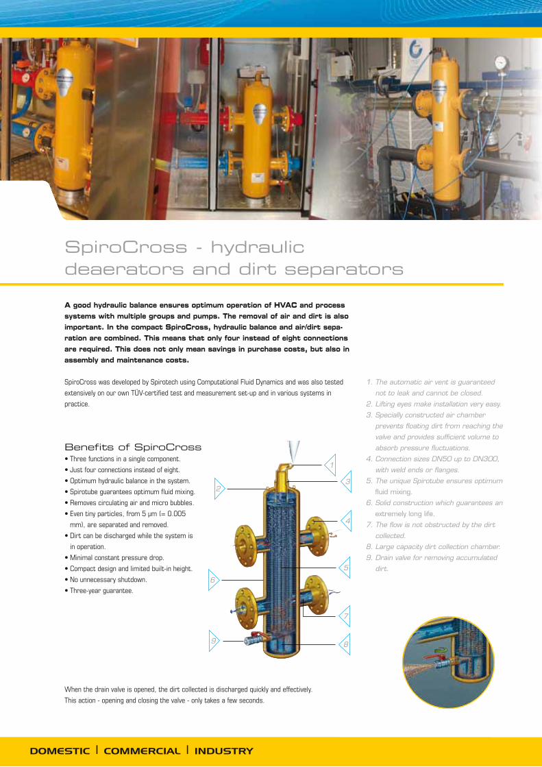
A good hydraulic balance ensures optimum operation of HVAC and process systems with multiple groups and pumps. The removal of air and dirt is also important. In the compact SpiroCross, hydraulic balance and air/dirt sepa-ration are combined. This means that only four instead of eight connections are required. This does not only mean savings in purchase costs, but also in assembly and maintenance costs.
SpiroCross was developed by Spirotech using Computational Fluid Dynamics and was also tested
extensively on our own TÜV-certified test and measurement set-up and in various systems in
practice.
When the drain valve is opened, the dirt collected is discharged quickly and effectively.
This action - opening and closing the valve - only takes a few seconds.
Benefits of SpiroCross
mm), are separated and removed.
in operation.
DOMESTIC | COMMERCIAL | INDUSTRY
6
1. The automatic air vent is guaranteed
not to leak and cannot be closed.
2. Lifting eyes make installation very easy.
3. Specially constructed air chamber
prevents floating dirt from reaching the
valve and provides sufficient volume to
absorb pressure fluctuations.
4. Connection sizes DN50 up to DN300,
with weld ends or flanges.
5. The unique Spirotube ensures optimum
6. Solid construction which guarantees an
7. The flow is not obstructed by the dirt
collected.
8. Large capacity dirt collection chamber.
9. Drain valve for removing accumulated
dirt.
T2 T1T4 T3
T1 T2T3 T4
QP QPQS QS
T2 T1T4 T3
T1 T2T3 T4
QP QPQS QS
T2 T1T4 T3
T1 T2T3 T4
QP QPQS QS
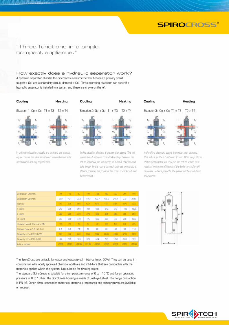
Connection DN (mm) 50 65 80 100 125 150 200 250 300
Connection OD (mm) 60.3 76.1 88.9 114.3 139.7 168.3 219.1 273 323.9
H (mm) 815 905 999 1261 1546 1781 2321 2870 3388
h (mm) 240 305 360 460 560 670 870 1100 1295
L (mm) 260 260 370 370 525 525 650 750 850
LF (mm) 350 350 470 475 635 635 775 890 1005
Primary Flow at 1.5 m/s (m3/h) 12,5 20 27 47 72 108 180 288 405
Primary Flow at 1.5 m/s (l/s) 3.5 5.5 7.5 13 20 30 50 80 113
Capacity ( T = 200C) (k/W) 294 462 630 1092 1680 2520 4200 6720 9450
Capacity ( T = 60C) (k/W) 88 139 189 328 504 756 1260 2016 2835
Article number XC050 XC065 XC080 XC100 XC050 XC125 XC150 XC250 XC300
How exactly does a hydraulic separator work?A hydraulic separator absorbs the differences in volumetric flow between a primary circuit
(supply = Qp) and a secondary circuit (demand = Qs). Three operating situations can occur if a
hydraulic separator is installed in a system and these are shown on the left.
The SpiroCross are suitable for water and water/glycol mixtures (max. 50%). They can be used in
combination with locally approved chemical additives and inhibitors that are compatible with the
materials applied within the system. Not suitable for drinking water.
The standard SpiroCross is suitable for a temperature range of 0 to 110 ºC and for an operating
pressure of 0 to 10 bar. The SpiroCross housing is made of unalloyed steel. The flange connection
on request.
Cooling Heating Cooling Heating Cooling Heating
Situation 1: Qp = Qs T1 = T3 T2 = T4 Situation 2: Qp < Qs T1 > T3 T2 = T4 Situation 3: Qp > Qs T1 = T3 T2 > T4
equal. This is the ideal situation in which the hydraulic
separator is actually superfluous.
In this situation, demand is greater than supply. This will
cause the T between T3 and T4 to drop. Some of the
return water will join the supply, as a result of which it will
take longer for the rooms to reach their set temperature.
Where possible, the power of the boiler or cooler will then
be increased.
In the third situation, supply is greater than demand.
This will cause the T between T1 and T2 to drop. Some
of the supply water will now join the return water, as a
result of which the efficiency of the boiler or cooler will
decrease. Where possible, the power will be modulated
downwards.
“Three functions in a single compact appliance.”
DOMESTIC | COMMERCIAL | INDUSTRY
Quantity Art. no.
SpiroPlus Cleaner Dirt dissolver 10 litre CC010
SpiroPlus LimeCleaner Descaler 10 litre CL010
SpiroPlus Sealer Leak sealer 1 litre CS001
SpiroPlus Sealer Leak sealer 2.5 litre CS0025
SpiroPlus Sealer Leak sealer 10 litre CS010
2.5 litre CA0025
10 litre CA010
60 litre CA060
200 litre CA200
Product overview
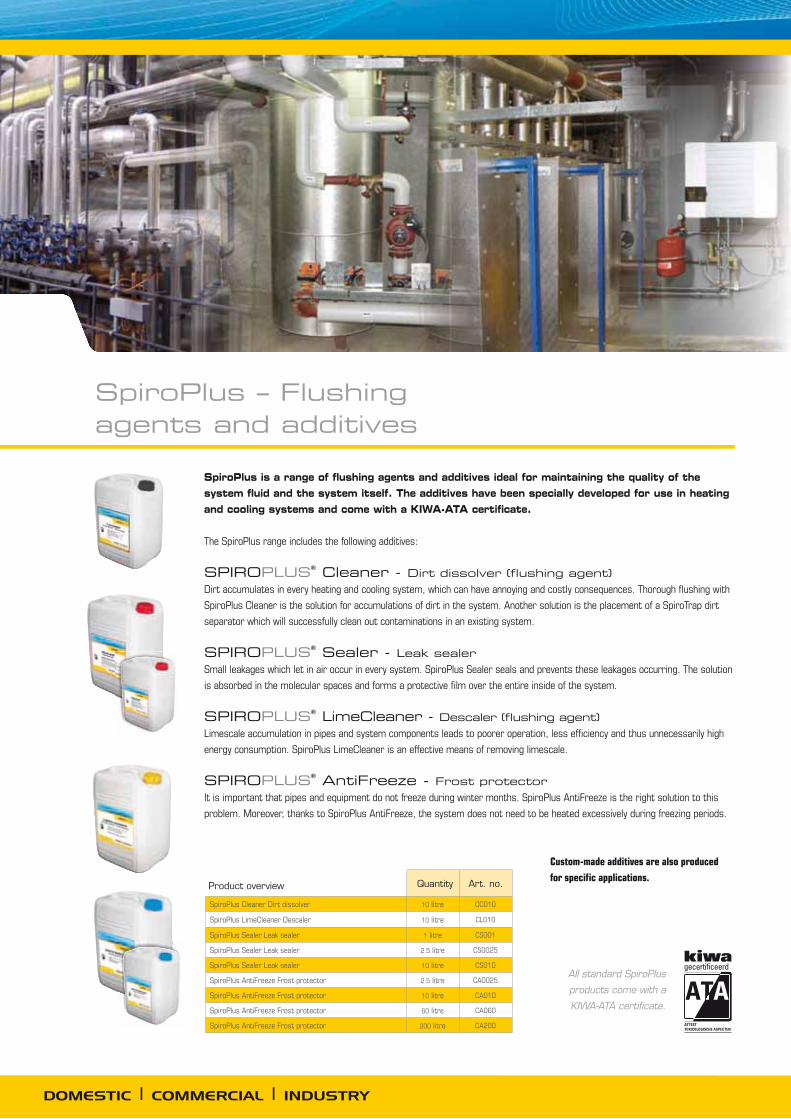
SpiroPlus – Flushing agents and additives
SpiroPlus is a range of flushing agents and additives ideal for maintaining the quality of the system fluid and the system itself. The additives have been specially developed for use in heating and cooling systems and come with a KIWA-ATA certificate.
The SpiroPlus range includes the following additives:
SPIROPLUS Cleaner - Dirt dissolver (flushing agent)Dirt accumulates in every heating and cooling system, which can have annoying and costly consequences. Thorough flushing with
SpiroPlus Cleaner is the solution for accumulations of dirt in the system. Another solution is the placement of a SpiroTrap dirt
separator which will successfully clean out contaminations in an existing system.
SPIROPLUS Sealer - Leak sealerSmall leakages which let in air occur in every system. SpiroPlus Sealer seals and prevents these leakages occurring. The solution
is absorbed in the molecular spaces and forms a protective film over the entire inside of the system.
SPIROPLUS LimeCleaner - Descaler (flushing agent)Limescale accumulation in pipes and system components leads to poorer operation, less efficiency and thus unnecessarily high
energy consumption. SpiroPlus LimeCleaner is an effective means of removing limescale.
SPIROPLUS AntiFreeze - Frost protector
Custom-made additives are also produced
for specific applications.
All standard SpiroPlus
products come with a
KIWA-ATA certificate.
SpiroCare - analysis and advice
“SpiroCare: made-to-measure solutions for your fluid carrying system.”
Under the name SpiroCare, Spirotech advises customers on the best possible treatment for water-carrying systems. The total solution chosen will comprise an effective combination of deaerators and dirt separators, combined with the right additives and, where necessary, backed up by periodic inspections. Spirotech has its own specialised laboratory and team of experienced experts. Customers are provided with an extensive report containing advice on suitable water treatments.
Our service range:
We have developed an integrated range of products and services to improve the performance
of both new designs as well as existing processes. SpiroCare provides solutions and innovations
to help maximise system running time and service life, decrease maintenance, save energy and
improve the quality of the product.
SpiroCare offers its customers added value:
L
H1 d
R1/2"
130
Ø65
DOMESTIC | COMMERCIAL | INDUSTRY
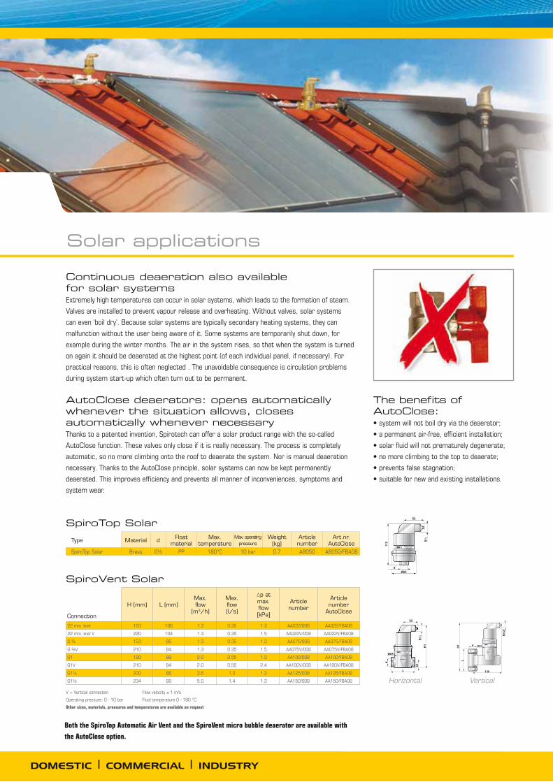
Continuous deaeration also available for solar systems Extremely high temperatures can occur in solar systems, which leads to the formation of steam.
Valves are installed to prevent vapour release and overheating. Without valves, solar systems
can even ‘boil dry’. Because solar systems are typically secondary heating systems, they can
malfunction without the user being aware of it. Some systems are temporarily shut down, for
example during the winter months. The air in the system rises, so that when the system is turned
on again it should be deaerated at the highest point (of each individual panel, if necessary). For
practical reasons, this is often neglected . The unavoidable consequence is circulation problems
during system start-up which often turn out to be permanent.
AutoClose deaerators: opens automatically whenever the situation allows, closes automatically whenever necessaryThanks to a patented invention, Spirotech can offer a solar product range with the so-called
AutoClose function. These valves only close if it is really necessary. The process is completely
automatic, so no more climbing onto the roof to deaerate the system. Nor is manual deaeration
necessary. Thanks to the AutoClose principle, solar systems can now be kept permanently
deaerated. This improves efficiency and prevents all manner of inconveniences, symptoms and
system wear.
VerticalHorizontal
The benefits of AutoClose:
H (mm) L (mm)Max. flow
[m3/h]
Max. flow [l/s]
p at max. flow [kPa]
Article number
Article number
AutoClose
22 mm. knel 153 106 1.3 0.35 1.3 AA022/008 AA022/FBA08
22 mm. knel V 220 104 1.3 0.35 1.5 AA022V/008 AA022V/FBA08
153 85 1.3 0.35 1.3 AA075/008 AA075/FBA08
210 84 1.3 0.35 1.5 AA075V/008 AA075V/FBA08
G1 180 88 2.0 0.55 1.3 AA100/008 AA100/FBA08
G1V 210 84 2.0 0.55 2.4 AA100V/008 AA100V/FBA08
G1¼ 200 88 3.6 1.0 1.3 AA125/008 AA125/FBA08
234 88 5.0 1.4 1.3 AA150/008 AA150/FBA08
SpiroVent Solar
Type Material d Float material
Max. temperature
Max. ope rating pressure
Weight[kg]
Article number
Art.nr. AutoClose
SpiroTop Solar Brass PP 180°C 10 bar 0.7 AB050 AB050/FBA08
SpiroTop Solar
V = Vertical connection Flow velocity ≤ 1 m/s
Operating pressure: 0 - 10 bar Fluid temperature 0 - 180 °C
Other sizes, materials, pressures and temperatures are available on request
Connection
Both the SpiroTop Automatic Air Vent and the SpiroVent micro bubble deaerator are available with
the AutoClose option.
Solar applications

Spirotech products and services not only offer attractive benefits for systems. Everyone involved stands to benefit from what Spirotech has to offer, from advisers, designers, distributors and installers to system users and maintenance people.
Guaranteed top qualitySpirotech delivers the quality you can expect of a specialist. The basis for this is high quality
materials, but there’s more to it than that: our experts closely monitor every stage of the
production process. One of the key quality requirements is that our products are leak proof. Thanks
to strict inspections and the painstaking care taken by our people in the production process, you
can rest assured that Spirotech’s products are 100% leak proof and that they function perfectly.
CertifiedWe are constantly improving our products and processes. It goes without saying that we are
certified for quality (NEN-EN-ISO 9001), environmental management (NEN-EN-ISO 14001) and
health and safety (OHSAS 18001).
Custom-made solutions and OEM applications Spirotech offers not only standard products. If necessary, we work with customers to produce
custom-made solutions. These are based on users’ specific requirements. If desired, these can also
be supplied as OEM products.
Add-on sets
Spirotech provides complete add-on sets for
vertical oil and gas boilers with distributors and
mixing groups which are ready for use. These
can be installed between the boiler and the
mixing group.
Insulation
Specially made insulation sets are available for
most deaerators and dirt separators.
Separate literature is available which contains detailed product information. You can also find this information on our website.
Digital support
Product data sheets, standard specification
texts, line drawings, CAD symbols, project
descriptions, etc. are available via our website.
Better for the system; benefits for everyone

14.4
54-0
2/09
09
Spirotech designs and produces innovative total solutions for conditioning fluids in HVAC and
process systems. Our products and services reduce faults and wear, less maintenance is required,
performance is improved and energy consumption is reduced.
Spirotech is deservedly regarded as the only real specialist in the world. Leading manufacturers of
system components recommend Spirotech products on account of their high standard of quality and
the company’s vision on product development and process improvement.
Thanks to a very extensive international network of suppliers, users all over the world enjoy the
benefits of our products and services every day.
Spirotech is a Spiro Enterprises company.
Spirotech: accessories, additives and advice
Spirotech UK Ltd.P.O. Box 109 Glossop
Derbyshire SK13 1WT
Phone: +44 (0)208 451 3344
Fax: +44 (0)208 451 3366
E-mail: [email protected]
Internet: www.spirotech.co.uk
Spirotech bvP.O. Box 207
5700 AE Helmond, The Netherlands
Tel.: +31 (0)492 578 989
Fax: +31 (0)492 541 245
E-mail: [email protected]
Internet: www.spirotech.com
The diagrams and situations presented in this brochure are only intended to serve as examples. We would be pleased to advise you on any specific situations. Modifications and printing/typographic errors reserved. ©Copyright Spirotech bv. No part of this publication may be used without prior written permission from Spirotech bv.