Embed Size (px)
Citation preview
Microcomputers in Civil Engineering 7 ( 1992) 20 1-22 I
Optimum Design System for Steel Cable-Stayed Bridges Dealing with Shape, Sizing Variables and
Cable Prestresses
Sadaji Ohkubo, Kazuhiro Taniwaki Department of Civil and Ocean Engineering, Ehime University, Matsuyama, Ehime, 790 japan
& Nagahiro Yamano
Kawada Technosystem Co. Ltd, 2-40-3 Nishinippori, Tokyo, 7 76 lapan
Abstract : A general-purpose, rigorous and eficient optimum design system for steel cable-stayed bridges is developed, in which not only can the cable anchor positions on the main girder and pylon, and the cross- sectional dimensions of the member elements be dealt with as design variables, but also the pseudo-loads applied to the cables. A powerful two-stage optimum design method is proposed to determine the optimum values of design variables for the cost minimization problem under stress constraints. At the first-stage optimization process, the cable arrangement and sizing variables are optimized by using the approximate concept and dual method with mi.lced directlinverse design variables. Then the optimum values of pseudo- loads, which induce the optimum prestresses into the cables, and the optimum sizing variables are determined so as to minimize the total cost of the bridge further by utilizing the sensitivities with respect to the pseudo-loads and a modified linear programming algorithm. The rigorousness, eficiency and practical usefulness of the proposed optimum design system are demonstrated by giving numerical design examples and the investigations of the optimum solutions at various design conditions. The significances of dealing with cable anchor positions and pseudo-loads as design variables are also emphasized.
1 INTRODUCTION
The cable-stayed bridge is one of the most attractive
types of bridge due to its ability to overcome large spans and its economical and aesthetic excellences. Bridges of this type have been constructed in a wide range of span lengths from 100 m to 800 m, throughout the world.
Because the cable-stayed bridge is a highly statically indeterminate structure, its structural behavior and total cost are greatly affected by the cable arrangement and stiffness distribution in the cables, main girder and pylon. Furthermore, the distribution of member forces, such as maximum and minimum bending moments and axial forces in the main girder and pylon, and cable tensions, can be controlled considerably by giving prestresses to cables. The aesthetic view of the bridge is also' affected by these design variables, therefore, it is very important that the bridge be designed by balancing totally the mechanical, economical and aesthetic charac- teristics, and the manufacturing and erection conditions. The establishment of a rational and efficient computer- aided design system for cable-stayed bridges, which can determine the optimum values of the design variables mentioned above at various design conditions rigorously and automatically, contributes significantly to the prac- tical design process for cable-stayed bridge.
The study of the optimum design of cable-stayed bridges was begun in the late 1970s. Yamada and Daiguji studied an optimum design method based on the optimality criteria." Kobayashi et al. presented a multilevel optimal design method by using the SLP algorithm and applied it to three types of cable-stayed bridges with different supporting ~ys tems.~ Gimsing' investigated the rational cable arrangement of cable-
20 1 Microcomputers in Civil Engineering 0885-9507/92/$05.00 0 1992 Elsevier Science Publishers Ltd
202 Suchji Olrkuho. K u ~ i ~ l r i r ~ ~ Tirtii\tdi & Nuguhiro Yuniuno
stayed bridges from the structural system analysis viewpoint. Yamada et al. studied the method for determination of cable prestresses based on the minimum strain energy ~r i te r i0n . l~ Hoshino investigated a practical method to determine the cable prestresses based on a structural analysis method using modified cross-sectional properties under the minimum cost ~r i te r ion .~ Nakamura and Wyatt determined the cable prestresses based on the limit states design code by using a linear programming algorithm.
In this paper a general-purpose, rigorous and efficient optimum design system for steel cable-stayed bridges is developed. In this design system, not only can the cable anchor positions on the main girder and pylon, and the cross-sectional dimensions of the cables, main girder and pylon elements be dealt with as design variables, but also the pseudo-loads applied to the cables. The design problem is formulated as a minimum-cost design problem subjected to the stress constraints taken from the Japanese Specifications for Highway Bridges." The cost-minimization problem is solved by a powerful two- stage optimum design process. During the first-stage optimization process, the cable arrangement and sizing variables are optimized by using approximate concept and dual method with mixed direct/inverse design variables. Then the optimum values of pseudo-loads, which induce the optimum prestresses into the cables, and the optimum sizing variables are determined so as to minimize the total cost of the bridge further by utilizing the sensitivities with respect to the pseudo-loads and a modified linear programming algorithm.
The proposed optimum design method has been applied to the minimum-cost design problems of practical-scale steel cable-stayed bridges. The theoretical rigorousness, efficiency and practical usefulness of the proposed optimum design system are demonstrated by giving several numerical design examples and investi- gations of the optimum solutions at various design conditions. The significances of dealing with the cable anchor positions on the main girder and pylon, and the pseudo-loads applied to the cables as design variables, are also emphasized for the minimum-cost designs of cable-stayed bridges.
2 FORMULATION OF OPTIMUM DESIGN PROBLEM
(1) Design variables
In this optimum design system, the span lengths, number of cables, height and width of the elements of the main girder and pylon, and material types to be used for each structural element are assumed as the preassigned
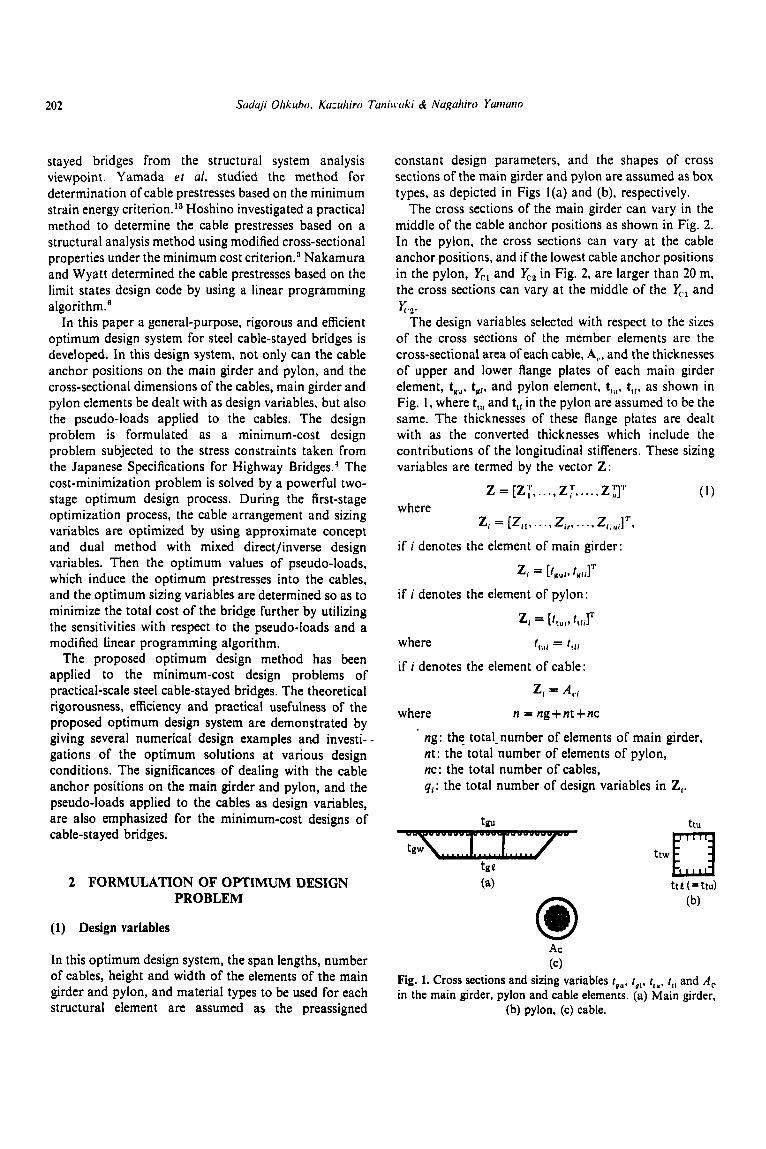
constant design parameters, and the shapes of cross sections of the main girder and pylon are assumed as box types, as depicted in Figs I(a) and (b), respectively.
The cross sections of the main girder can vary in the middle of the cable anchor positions as shown in Fig. 2. In the pylon, the cross sections can vary at the cable anchor positions, and if the lowest cable anchor positions in the pylon, x:l and V,, in Fig. 2, are larger than 20 m, the cross sections can vary at the middle of the q.l and
The design variables selected with respect to the sizes of the cross sections of the member elements are the cross-sectional area of each cable, A,,, and the thicknesses of upper and lower flange plates of each main girder element, tyu, t,,, and pylon element, t,,,, t,[, as shown in Fig. 1, where t,, and ttl in the pylon are assumed to be the same. The thicknesses of these flange plates are dealt with as the converted thicknesses which include the contributions of the longitudinal stiffeners. These sizing variables are termed by the vector Z:
( 1 ) where
if i denotes the element of main girder:
yc,.
z = [ZT, .. ., z;,. .., Z y "
z, = [Z , , , . . . , zi,. . . ., z I . , , i]''',
if i denotes the element of pylon:
where L,, = 4 1 , if i denotes the element of cable:
Z, = A,,
where n = ng+nt+nc
ng: the total-number of elements of main girder, nt: the- total number of elements of pylon, nc: the total number of cables, qr: the total number of design variables in Z,.
trm
Ac (c)
Fig. 1. Cross sections and sizing variables tvu, r g , , t,,, t , , and A , in the main girder, pylon and cable elements. (a) Main girder,
(b) pylon, (c) cable.
203
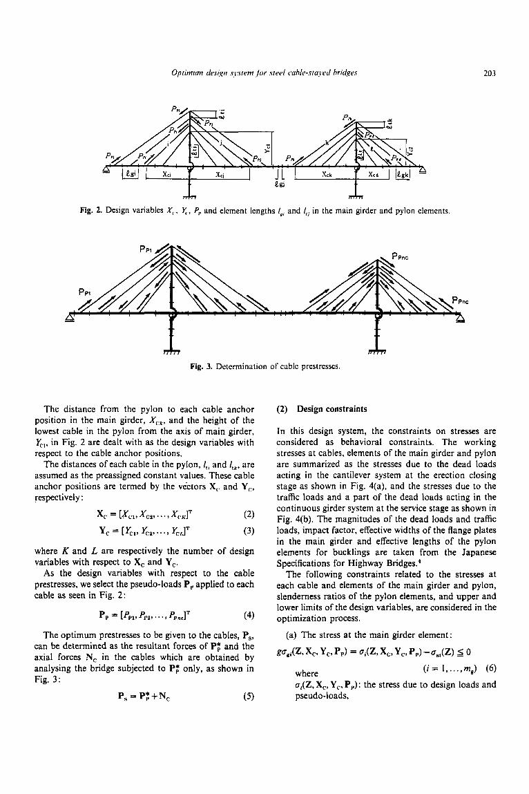
Fig. 2
T
. Design variables X,. x., f,, and element lengths lg, and I,, in the main girder and pylon elements.
Fig. 3. Dctcrmination of cable prestresses.
The distance from the pylon to each cable anchor position in the main girder, XC.*, and the height of the lowest cable in the pylon from the axis of main girder, U,.,, in Fig. 2 are dealt with as the design variables with respect to the cable anchor positions.
The distances of each cable in the pylon, I,, and ltkr are assumed as the preassigned constant values. These cable anchor positions are termed by the vectors X,. and Y,, respectively :
x, = [Xcp X C 2 , * * * , &KIT
y, = [&I, G2, * . . , &LIT
(2)
(3)
where K and L are respectively the number of design variables with respect to X, and Y,.
As the design variables with respect to the cable prestresses, we select the pseudo-loads Pp applied to each cable as seen in Fig. 2:
(4) P P = [PPl, PPZ,. - * 9 PpnclT
The optimum prestresses to be given to the cables, P,, can be determined as the resultant forces of P$ and the axial forces N, in the cables which are obtained by analysing the bridge subjected to P: only, as shown in Fig. 3 :
P, = P$+N, ( 5 )
(2) Design constraints
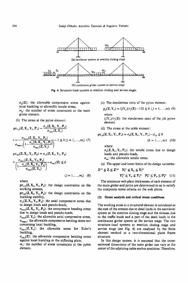
In this design system, the constraints on stresses are considered as behavioral constraints. The working stresses at cables, elements of the main girder and pylon are summarized as the stresses due to the dead loads acting in the cantilever system at the erection closing stage as shown in Fig. 4(a). and the stresses due to the traffic loads and a part of the dead loads acting in the continuous girder system at the service stage as shown in Fig. 4(b). The magnitudes of the dead loads and traffic loads, impact factor, effective widths of the flange plates in the main girder and effective lengths of the pylon elements for bucklings are taken from the Japanese Specifications for Highway bridge^.^
The following constraints related to the stresses at each cable and elements of the main girder and pylon, slenderness ratios of the pylon elements, and upper and lower limits of the design variables, are considered in the optimization process.
(a) The stress at the main girder element:
Vg*(Z, x,, y,, PP) = Oi(Z, x,, y,, Pp) -a,,(Z) 5 0 (i = 1, ..., mg) (6 ) where
a,(Z, X,, Y,. P,): the stress due to design loads and pseudo-loads,
204 Sadaji Ohkubo. Kazuhiro Taniwaki & Nagaliiro Yaniano
(a) cantilever system at erection closing stage
(b) continuous girder system at service stage
Fig. 4. Structure-load systems at erection closing and service stages.
o,,(Z) : the allowable compressive stress against (c) The slenderness ratio of the pylon element local buckling or allowable tensile stress, mm: the number of stress constraints at the main g,,(Z, Y,) = / , (Y , ) / r , (Z ) - 120 S 0 ( j = 1, . . . , nr) (9)
giider element. where
(b) The stress at the pylon element: /,(YJ/r,(Z): the slenderness ratio of the j t h pylon element.
(d) The stress at the cable element:
oak: the allowable tensile stress.
(e) The upper and lower limits of the design variables:
z = (I) < z s - Z(”) xg) 6 x, xy
where go,,,(Z, Xc, Yc, Pp): the design constraints on the working stresses, go,,,(Z, Xc, Y,, Pp): the design constraints on the buckling stability, ac,(Z, X,, Y,, Pp) : the axial compressive stress due to design loads and pseudo-loads, bbcyj(z, X,, Yc, Pp) : the compressive bending stress due to design loads and pseudo-loads, ocaz,(Z, Yc) : the allowable axial compressive stress, oh,,, : the allowable compressive bending stress not concerning local buckling, oeayl(Z, Y,): the allowable stress for Euler’s buckling, oca,,(Z) : the allowable compressive bending stress against local buckling in the stiffening plate, m,: the number of stress constraints at the pylon element.
The minimum web plate thicknesses of each element of the main girder and pylon are determined so as to satisfy the composite stress criteria on the web plates.
(3) Stress analysis and critical stress conditions
The working stress at a structural element is calculated as the sum of the stresses due to dead loads in the cantilever system at the erection closing stage and the stresses due to the traffic loads and a part of the dead loads in the continuous girder system at the service stage. The two structure-load systems at erection closing stage and service stage (see Fig. 4) are analysed by the finite element method as a two-dimensional plane frame structure. In this design system, it is assumed that the cross-
sectional dimensions of the main girder can vary at the center of the adjoining cable anchor positions. Therefore,
Oplimirm design
I cable
s.4
system ,for steel cable-stayed bridges
4tj I SB
205
subject to / upper flange plate
M.4 MR
- - 4
4 ni I SB sA lower flange plate
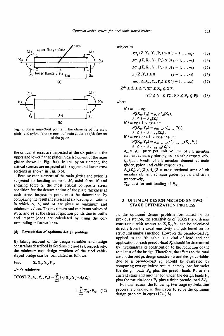
the critical stresses are inspected at the six points in the upper and lower flange plates in each element of the main girder shown in Fig. 5(a). In the pylon element, the critical stresses are inspected at the upper and lower cross sections as shown in Fig. 5(b).
Because each element of the main girder and pylon is subjected to bending moment M , axial force N and shearing force S, the most critical composite stress condition for the determination of the plate thickness at each stress inspection point must be determined by comparing the resultant stresses at six loading conditions in which N, S, and M are given as maximum and minimum values. The maximum and minimum values of N, S, and M at the stress inspection points due to traffic and impact loads are calculated by using the cor- responding influence lines.
(4) Formulation of optimum design problem
By taking account of the design variables and design constraints described in Sections (1) and (2), respectively, the minimum-cost design problem of the steel cable- stayed bridge can be formulated as follows:
Find z, x,, y,, p,,
which minimize
TCOST(Z, X,, Y,, P,) = n
ct: (X,, Yc) -A&) L-1
nc
+ c TPk*PPk (12) k-1
where
if i = 1 - ng: wx,, YC) = Pgi * /JXCL Ai(Zi) = Agi(Zi);
Y(X,, Y,) = Ptci-au) .ft(i-,ig)(Y(.)- Adz,) = At(l-ng)(Zi);
if i = ng+ 1 - ng+nr:
if i = ng+nt+ 1 - ng+nt+nc: KK.9 YJ = P c ( i - n y - r d t ) .'c(i-ng-rit)(X(:, Yc.), Ai(Zi) = Ac(i-ng-rit)(Zi);
pai,pti,p,.i: price per unit volume of ith member element at main girder, pylon and cable respectively, l K i , / t i , / c i : length of ith member element at main girder, pylon and cable respectively, AKi(Zi), Ati(Zi), A,,(Zi) : cross-sectional area of ith member element at main girder, pylon and cable respectively, Tpk: cost for unit loading of P,,.
3 OPTIMUM DESIGN METHOD BY TWO- STAGE OPTIMIZATION PROCESS
In the optimum design problem formulated in the previous section, the sensitivities of TCOST and design constraints with respect to Z, X,, Y, can be calculated directly from the usual sensitivity analysis based on the structural analysis method. However the pseudo-load Ppt applied to the ith cable is a kind of load and the application of each pseudo-load Ppt should be determined by investigating its contribution to the reduction of the total cost of the bridge. Therefore, the effects to the total cost of the bridge, design constraints and design variables due to a pseudo-load PpL should be evaluated by comparing two optimized results, namely, one for under the design loads P, plus the pseudo-loads P, at the current stage and another for under the design loads P, plus the pseudo-loads P, plus a finite pseudo-load UP1.
For this reason, the following two-stage optimization process is proposed in this paper to solve the optimum design problem in eqns (12)-( 18).
206 Saduji Ohkubo, Kazrihiro Tuniwki & Naguhirn Yaniano
At the first-stage optimization process, Z, X,, Y, or the selected design variables among Z, X[,, Y, by the designer are dealt with as the design variables."' Utilizing the convex and linear approximation concept developed by Fleury et al.,1.7*10a11 the objective function and the behavior constraints are approximated by using first- order partial derivattves and Z, Xr, Y, and the inverse variables 1 /Z, I /X(,, I /Y,. The approximate subproblem is solved by the dual method. In this optimization process, the adaptive move limit constraints, maximum lo%, are imposed on the changing rates of X, and Y,, to ensure smooth convergence to the optimum solutions. The optimized TCOST, Z, X, and Y, under the design loads at this stage are denoted as TCOST*(P,), Z*(P,), X:(P,) and Y,t(P,,).
As it will be described in the design examples, the effects of the optimum pseudo-loads to the optimum cable anchor positions X,* and Y r are negligibly small. Therefore, after the first-stage optimization process, X,*(P,) and Y:(Plt) are fixed, and a finite value of pseudo-load DC,[ is applied to the ith cable in addition to the design loads P,, and the pseudo-loads P,, at the current stage. The cable-stayed bridge is optimized again dealing with Z only, by utilizing the first-stage optim- ization algorithm described above. The optimized TCOST, g and Z by this process are denoted as TCOST"(P,+P,2+D,,), go(P,+P,+D,,) and Zo(P, + P, +bP,,). The approximate sensitivities of TCOST, g and 2 with respect to P,, are then calculated by a finite difference formula using the two optimum solutions obtained under the loads P, + P, and the loads P,+P,+D, , . Then a linear programming problem in terms of the finite increments or decrements of pseudo- loads, + A P , or -APE (where k denotes the iteration number), is formulated utilizing the sensitivities obtained above and the move limit constraints on +APE and -APE. The increments or decrements of pseudo-loads, +Apt or -APE, to be applied to the cables for minimizing the objective function are determined with the aid of a modified linear programming algorithm, and the changes in 2, AZk, due to +Apt or -APE are calculated from the sensitivities of Z with respect to P,,.
The cable-stayed bridge with Zk = Z* + C AZk is re- optimized for the combined effect of the design loads P,
and the improved pseudo-loads PE = CAPE (or P*p = Pt-' + AP",. The improvements of P, are iterated until TCOST converges to the minimum value.
k
k
4 FIRST-STAGE OPTIMIZATION
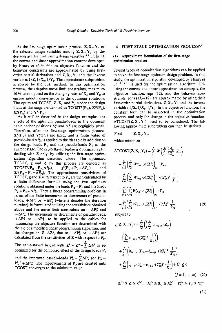
(1) Approximate formulation of the first-stage optimization problem
Several types of optimization algorithms can be applied to solve the first-stage optimum design problem. In this study, the optimization algorithm developed by Fleury el ~ f . ' ~ ' * ' ~ . " is used for the optimization algorithm. Uti- lizing the convex and linear approximation concepts, the objective function, eqn ( 1 2), and the behavior con- straints, eqns ( 1 3)-( 18), are approximated by using their first-order partial derivatives, Z, X,, Y,. and the inverse variables l/Z, l/X(., l /Yr. In the objective function, the constant term can be neglected in the optimization process, and only the change in the objective function, ATCOST(Z, Xr, Y(.), need to be considered. The fol- lowing approximate subproblem can then be derived :
Find z, X[V YC.
which minimize
'li 3AIr ATCOST( Z. X[~, Y (.) = H( (C -..I.> i - 1 r -1 azir
(92)
(sz)
LO2
208 Suduji Ohkubo, Kuzuhiro Tuniwaki & Nugahiro Yurnuno
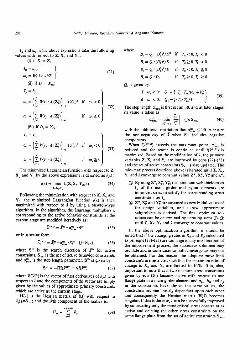
Ti and w, in the above expressions take the following values with respect to Z, X, and Y,:
(i) if D, = Zir:
(iii) if D, = Yo:
Ti = 5 1
if w, 2 0 w, = [i -1 wu,;a,(z:,) (+)
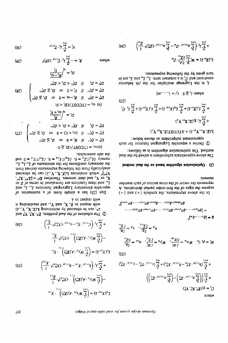
The minimized Lagrangian function with respect to Z, X, and Y, by the above expressions is denoted as / ( A ) :
/ (A ) = min L(Z, X,, Y,, A ) (34) z. xc, Yc
Following the minimization with respect to Z, X, and Y,, the minimized Lagrangian function / ( I ) is then maximized with respect to I by using a Newton-type algorithm. In the algorithm, the Lagrange multipliers I corresponding to the active behavior constraints at the current stage are modified iteratively as:
(35)
( j c S A G ) (36) where S” is the search direction of 2’) for active constraints, SAG is the set of active behavior constraints and a:;x is the step length parameter. St) is given by
(37)
where V/(z”,) is the vector of first derivatives of [(A) with respect to Xand the components of the vector are simply given by the values of approximate primary constraints which are active at the current stage.
H ( I ) is the Hessian matrix of / ( I ) with respect to A1(jcSAa) and the jkth component of the matrix is:
z(t+l) zt) .+ s(t)
or in a scalar form qttl) = n7”’ + .141,, qt)
S(t) = - [H(lt7”)]-’ * V@”)
n+K+L
H j k = c B,Y (38) I-1
where B, = Q,.(D:)4/D: if q, c 0, q, < 0
B, = Q;(D;)*/D, if 2 0, &, < 0
B, = Q i . (Dp)‘/D, if Ti < 0, q, 2 0
B, = Q i * D i if q, 2 0, q, 2 0
Qi is given by:
if o, 2 0: Q, = i.T,,-T,,/(w,+ K ) \ (39)
if o , < o : Q , = ~ . T , - T , , / ~ J The step length a:\x is first set as 1.0, and at later stages its value is taken as
with the additional restriction that 1.0 to ensure the non-negativity of X when S’) includes negative components.
When exceeds the maximum point, is reduced and the search is continued until /($‘+”) is maximized. Based on the modification of 1, the primary variables Z, X, and Y,, are improved by eqns (27)-(33) and the set of active constraints SAG is also updated. The min-max process described above is iterated until Z, X,, Y,. and I converge to constant values Z*. X& Y: and A*.
@ By using Z*, X:, Y,“, the minimum web thicknesses t, of the main girder and pylon elements are improved so as to satisfy the corresponding stress constraints on t,.
@ Z*, X,“ and Y: are assumed as new initial values of the design variables, and a new approximate subproblem is derived. The final optimum sol- utions can be determined by iterating steps @-@ until Z, X,, Y, and I converge to constant values.
In the above optimization algorithm, it should be noted that if the changing rates in X, and Y, calculated as per eqns (27)-(33) are too large in any one iteration of the improvement process, the successive solutions may oscillate and in some cases smooth convergence may not be obtained. For this reason, the adaptive move limit constraints are restricted such that the maximum rates of change in X, and Y, are limited to 10%. It is, also, important to note that if two or more stress constraints given by eqn (20) become active with respect to one flange plate in a main girder element and a,,,, b,, and cjI in the constraints have almost the same values, the constraints become linearly dependent upon each other and consequently the Hessian matrix H(Z) becomes singular. If this is the case, A can be successfully improved by considering only the most critical stress constraint as active and deleting the other stress constraints on the same flange plate from the set of active constraints SAG.
Oprimum design system for steel cable-stayed bridges 209
(3) Calculation of uji,, bjk and cj,
all , , b,, and clr in eqn (20) are calculated by using the partial derivatives of NE, ME, N, and 3lY with respect to Zirr X,, and Y,, respectively where N, and ME denote the axial forces and bending moments in the cantilever system at the erection closing stage and N, and M, denote those in the continuous girder system at the service stage. In this study, the partial derivatives are calculated by a finite difference method. In the cal- culation, the changes in the dead loads due to the changes in Z, X, and Y, and the changes in the loading positions of traffic loads due to the changes in X, are evaluated. However, the changes in the loading positions of the traffic loads due to the changes in Z and Y, are neglected.
The optimum TCOST, Z, X, and Y, obtained by the first-stage optimization process which accounts for the design loads only are denoted as TCOST*(P,), Z*(P,), X,*(P,) and Y:(P,), respectively.
5 SECOND-STAGE OPTIMIZATION PROCESS
(1) Calculation of sensitivities with respect to pseudo- loads P,
As described in Section 3, the optimum pseudo-loads P, are determined by using a modified linear programming algorithm. For the formulation of the linear program- ming problem, the sensitivities of the total cost, the stress constraints and cross-sectional dimensions with respect to the pseudo-loads P, need to be calculated.
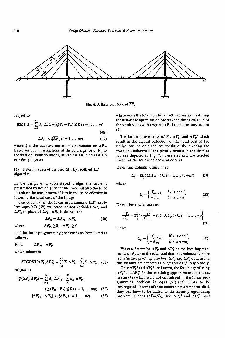
The optimum cable anchor positions X,*(P,) and Y:(P,) determined during the first-stage optimization process by considering only the design loads are found to be scarcely affected by the optimum pseudo-loads as seen in the design examples. Therefore, Xr(P,) and Y,*(P,) are fixed in the second-stage optimization process. In the calculation of the sensitivities with respect to the ith pseudo-load P,,, a finite value of pseudo-load DPf is applied to the ith cable, as shown in Fig. 6, in addition to the design loads P, and the current psuedo-loads P,. The cost minimization problem of the cable-stayed bridge subjected to P,, P, and D,, can then be formulated as :
Find Z(P,+P ,+~ , f ) , which minimize
TCOST(P, + P, +up,)
subject to gj(p,+pp+dpp{) 5 0 (i= 1 , . . . , M ) (42)
Z"' 5 Z(PR + P, + Bp,,) 5 Z(U' (43) In the above formulation, Z is the only design variable.
Tpl is the cost for unit loading of PpI and as it is reasonable to assume T,, z 0 in practice its value is taken as 0 in our design system.
The optimum design problem formulated in eqns (19)-(22) can be solved quite readily by using the first- stage optimization algorithm. The cost of computing the final optimum pseudo-load Ppf is affected considerably by the magnitude o f D P i . After an initial investigation of the convergence to the optimum P,, we determined the upper limit of the magnitude of npi as 5 % of the maximum cable tension produced by the design loads in the ith cable. The optimum TCOST, g and Z obtained by solving the optimum design problem in eqns (41)-(43) are denoted, respectively, as TCOST"(P, + P, + D,J, go(PR+Pp+Dpi) and Zo(P,+Pp+l?(pPl).
The approximate sensitivities of TCOST, g, and Z,, with respect to Ppl, denoted as I;, d,, and e,,,, are calculated using the following finite difference formula :
?;= aTCOST(hP,,)
dPPi
(44) TCOST"(P,, + PI, + DPi) - TCOSTo( P, + P,) - - -
''pi
azkr(DPi) Iu c1 z",r(plt + + DPI) - -Z",r('R + 'P)
ap,, APPi e k r i =
(46)
where TCOSTo(P, + P,), go@, + p,) and p@, + pp> are, respectively, the optimum values of TCOST, g, and z,, of the bridge subjected to the design loads P, and pseudo-loads P,.
(2) Formulation of linear programming problem
Utilizing the above sensitivities, the objective function TCOST and the design constraints g are approximated to the linear expressions on AP,. Consequently, a linear programming problem is derived for the determination of the improvements of P,, AP,, so as to reduce the total cost of the bridge. This can be stated as:
Find APP,
which minimize nc
ATCOST(AP,) = T*APpf I-1
(47)
E M C 7 16
210 Sadaji Ohkubo, Kazukiro Taniwaki & Nagahiro Yamano
Fig. 6. A finite pseudo-load Dp,.
subject to nc
&@PA= C~j , .A~pI+gj (P ,+P , ) s O ( j = l , . . . ,m)
IAP,J <tDp,(i= 1, ..., nc)
I- 1
(48)
(49)
where t is the adaptive move limit parameter on AP,,. Based on our investigations of the convergence of P,. to the final optimum solutions, its value is assumed as 4.0 in our design system.
(3) Determination of the best AP, by modified LP algorithm
In the design of a cable-stayed bridge, the cable is prestressed by not only the tensile force but also the force to reduce the tensile stress if it is found to be effective in lowering the total cost of the bridge.
Consequently, in the linear programming (LP) prob- lem, eqns (47)-(49), we introduce new variables APpl and AFpt in place of AP,,. APpi is defined as:
(50) AP,, = AP,, - A c , where AP, 20, A c t 2 0
and the linear programming problem is re-formulated as follows :
Find AP,, AP",, which minimize
ne ne ATCOST(APk,APg) = C T*APIp,- CT,*Ahp",, (51)
(-1 t-1
subject to nc ne
j $ A c , AP;) = C dj, * Ap'p, - C d,, * AP",, 1-1 (-1
+g,(P, + Pp) I 0 (j = 1, . . . , mp) (52)
IAP'pi - AGtl c tDPt (i = 1, . . . , nc) (53)
where mp is the total number of active constraints during the first-stage optimization process and the calculation of the sensitivities with respect to P, in the previous section
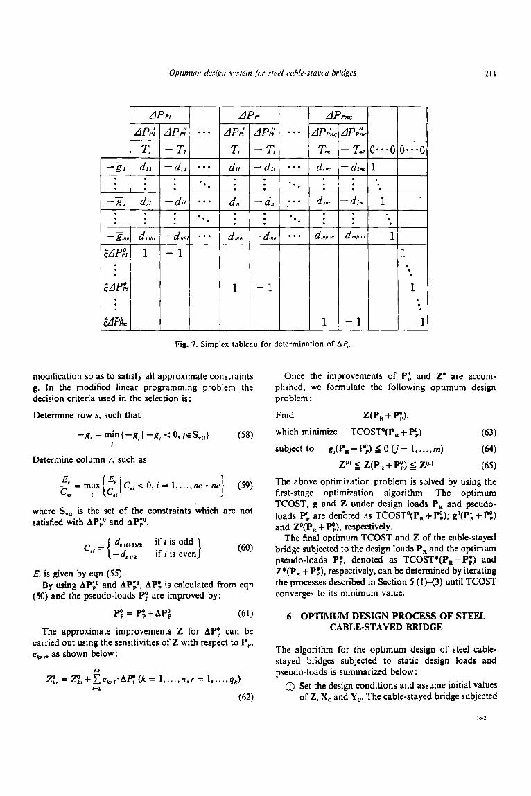
The best improvements of P,, AP;" and AP;" which result in the highest reduction of the total cost of the bridge can be obtained by continuously pivoting the rows and columns of the pivot elements in the simplex tableau depicted in Fig. 7. These elements are selected based on the following decision criteria:
Determine column r, such that
(1).
E,=min{&,IE,cO,i= 1, ..., nc+nc} (54) 1
where
( 5 5 )
Determine row s, such as
where
c,, = { dm+u/z if r is odd } (5,)
We can determine AP, and APG as the best improve- ments of P, when the total cost does not reduce any more from further pivoting. The best AF, and AP", obtained in this manner are denoted as APpo and APNp", respectively.
Once LIP,' and APgo are known, the feasibility of using APPo and AP;O for the remaining approximate constraints in eqn (48) which were not considered in the linear pro- gramming problem in eqns (51)-(53) needs to be investigated. If some of these constraints are not satisfied, they will have to be added to the linear programming problem in eqns (51)-(53), and APiO and AP;' need
- 4 r/2 if r is even
21 I
modification so as to satisfy all approximate constraints g. In the modified lineslr programming problem the decision criteria used in the selection is :
Determine row s, such that
Determine column r , such as
- max - c,, < 0, i = I , ..., nc+nc} (59) &- C,r i {:,I where S, , is the set of the constraints which are not satisfied with APP and AP;".
ds (1+1)/2 if is Odd ) (60) - d, 1,9 if i is even
E1 is given by eqn (55) .
(50) and the pseudo-loads P, are improved by: By using AP: and AP",O, AP, is calculated from eqn
PO, = PO,+APO, (61)
The approximate improvements Z for APO, can be carried out using the sensitivities of Z with respect to P,, e,,,, as shown below:
nc
ZO,, = g,+ e , , , .Ac (k = 1,. . . , n ; r = I , . . . , qr) 1-1
(62)
Once the improvements of Py> and Z" are accom- plished, we formulate the following optimum design problem :
Find w,, + PYA
which minimize TCOST"(P, + P",) (63) subject to gj(P, + P:.) S 0 ( j = I , . . . , m) (64)
Z'" Z(P,, + P;) Z(") (65) The above optimization problem is solved by using the first-stage optimization algorithm. The optimum TCOST, g and Z under design loads P, and pseudo- loads PO, are denbted 'as TCOSTo(P, + P",; go(P; + PO,) and Zo(P, + P",, respectively.
The final optimum TCOST and Z of the cable-stayed bridge subjected to the design loads P, and the optimum pseudo-loads Pp'. denoted as TCOST*(P,+Pf) and Z*(P, + P:), respectively, can be determined by iterating the processes described in Section 5 (1 H3) until TCOST converges to its minimum value.
6 OPTIMUM DESIGN PROCESS OF STEEL CABLE-STAYED BRIDGE
The algorithm for the optimum design of steel cable- stayed bridges subjected to static design loads and pseudo-loads is summarized below : 0 Set the design conditions and assume initial values
of Z, X, and Y,. The cable-stayed bridge subjected
212 Sadaji Ohkuho, Kaxhiro Tuniwaki & Nagahiro Yarnano
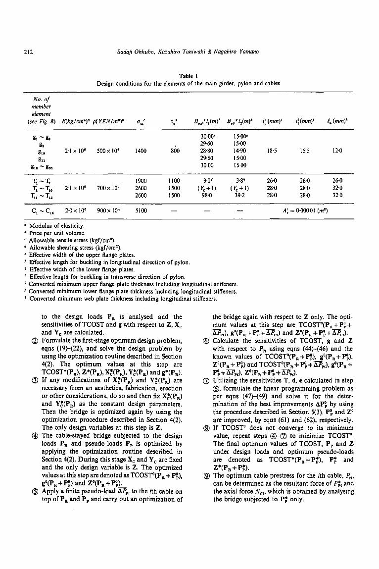
Table 1 Design conditions for the elements of the main girder, pylon and cables
No. of member element
(see Fig. 8) E(kg/cm2)" P ( Y E N / ~ ) ~ urnc r." Be,,* f,(m)* Be,: 1: (mm)' 11 (mm)' 1:. (mm)k
g, - g, 3O.0Oe 15.00~ go 29.60 15.00
g11 29.60 15.00 g10 2.1 x lo6 5 0 0 ~ lo4 1400 800 28.80 14.90 18.5 15.5 120
&a gao 3000 15.00
TI - T, I900 I100 3.0' 3%' 26.0 26.0 26.0 T, - Tl0 2.1 x 10' 700 x 10' 2600 1500 ( y , + 1 ) ( y , + 1 ) 28.0 28.0 32.0
TI1 - TI3 2600 I500 98.0 39.2 28.0 28.0 32.0 ~~~ ~ ~~
- A f = 0.00001 (ma) C, - C,, 2 0 x 10' 900 x 10' 5100 - -
(I
b
e
d
e
I
0
b
1
1
k
Modulus of elasticity. Price per unit volume. Allowable tensile stress (kgf/cm*). Allowable shearing stress (kgf/cma). Effective width of the upper flange plates. Effective length for buckling in longitudinal direction of pylon. Effective width of the lower flange plates. Effective length for buckling in transverse direction of pylon. Converted minimum upper flange plate thickness including longitudinal stiffeners. Converted minimum lower flange plate thickness including longitudinal stiffeners. Converted minimum web plate thickness including longitudinal stiffeners.
to the design loads P, is analysed and the sensitivities of TCOST and g with respect to Z, X, and Y, are calculated.
Q Formulate the first-stage optimum design problem, eqns (19)-(22), and solve the design problem by using the optimization routine described in Section 4(2). The optimum values at this step are
a If any modifications of X,+(P,J and Y,*(P,) are necessary from an aesthetics, fabrication, erection or other considerations, do so and then fix X,*(P,) and Y,*(P,) as the constant design parameters. Then the bridge is optimized again by using the optimization procedure described in Section 4(2). The only design variables at this step is Z.
@ The cable-stayed bridge subjected to the design loads P, and pseudo-loads P, is optimized by applying the optimization routine described in Section 4(2). During this stage X, and Y, are fixed and the only design variable is Z. The optimized values at this step are denoted as TCOSTo(P, + P",, go(P, + P:) and Zo(P, + P$>.
0 Apply a finite pseudo-load np, to the ith cable on top of P, and P, and carry out an optimization of
TCOST*(P,), Z*(P,), X,*(P,), Y:(P,) and g*(P,).
the bridge again with respect to Z only. The opti- mum values at this step are TCOSTO(P,+PO,+ AP,,), g"(P,+PO,+n,,) and Zo(P,+PO,+.L\pp,).
@ Calculate the sensitivities of TCOST, g and Z with respect to PpI using eqns (44H46) and the known values of TCOSTo(P, + P",, g'(P, + P,), P(P , + P:) and TCOSTo(P, + P! +n,,), go(P, +
8 Utilizing the sensitivities T, d, e calculated in step @, formulate the linear programming problem as per eqns (47)-(49) and solve it for the deter- mination of the best improvements APO, by using the procedure described in Section 5(3). P: and Zo are improved, by eqns (61) and (62), respectively.
QD If TCOSTO does not converge to its minimum value, repeat steps to minimize TCOSTO. The final optimum values of TCOST, P, and Z under design loads and optimum pseudo-loads are denoted as TCOST*(P,+P,*), Pp* and
@ The optimum cable prestress for the ith cable, P,,, can be determined as the resultant force of Pf, and the axial force Ncr, which is obtained by analysing the bridge subjected to Pp* only.
-
P: + D,,), ZO(P, + P: + D P J .
Z*(P, + P;).
Optimum design system for steel cable-stared bri&es 213
7 DESIGN EXAMPLES
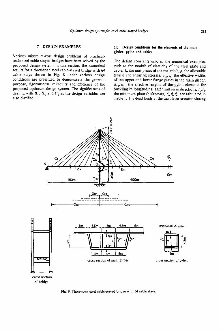
Various minimum-cost design problems of practical- scale steel cable-stayed bridges have been solved by the proposed design system. In this section, the numerical results for a three-span steel cable-stayed bridge with 64 cable stays shown in Fig. 8 under various design conditions are presented to demonstrate the general- purpose, rigorousness, reliability and efficiency of the proposed optimum design system. The significances of dealing with X,, Y, and P, as the design variables are also clarified.
(1) Design conditions for the elements of the main girder, pylon and cables
The design constants used in the numerical examples, such as the moduli of elasticity of the steel plate and cable, E, the unit prices of the materials, p, the allowable tensile and shearing stresses, nt,, r,, the effective widths of the upper and lower flange plates in the main girder, B,,,B,,, the effective lengths of the pylon elements for buckling in longitudinal and transverse directions, I,, f,, the minimum plate thicknesses, ti, t:, tfv. are tabulated in Table 1. The dead loads at the cantilever erection closing
6m - - 6.5,. . 5m . 6.5m 6m longitudinal direction
4m
cross section of pylon cross section of main girder
cross section of bridge
Fig. 8. Three-span steel cable-stayed bridge with 64 cable stays.
214 Suduji Ohkubo. Kuzuhiro Tuniwnki & Noguliiro Yuniuno
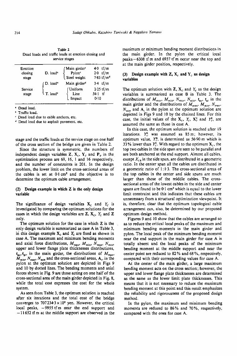
Table 2 Dead loads and traffic loads at erection closing and
service stages
Erection Main girderc 40 tf/m closing D. load" [ Pylon' 2.0 tf/m stage Steel weight 7.85 tf/m3
D. load" Main girderd 3.4 tf/m Uniform 2-25 tf/m
T. loadb 54.1 tf Service stage 1 Impact 0.10
Dead load. Traffic load. Dead load due to cable anchors, etc. Dead load due to asphalt pavement, etc.
stage and the traffic loads at the service stage on one half of the cross section of the bridge are given in Table 2.
Since the structure is symmetric, the numbers of independent design variables Z, X,, Y,: and P, in the optimization process are 69, 16, 1 and 16 respectively, and the number of constraints is 201. In the design problem, the lower limit on the cross-sectional areas of ;he cables is set at 0.1 cm2 determine the optimum cable
(2) Design example in which variable
The significance of design
and the objective is to arrangement.
Z is the only design
variables X, and Y, is investigated by comparingjhe optimum solkions for- the cases in which the design variables are 2, X,, & and Z only.
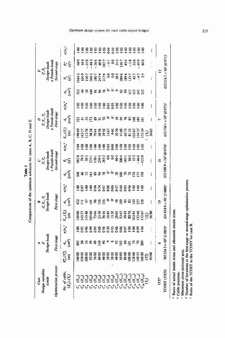
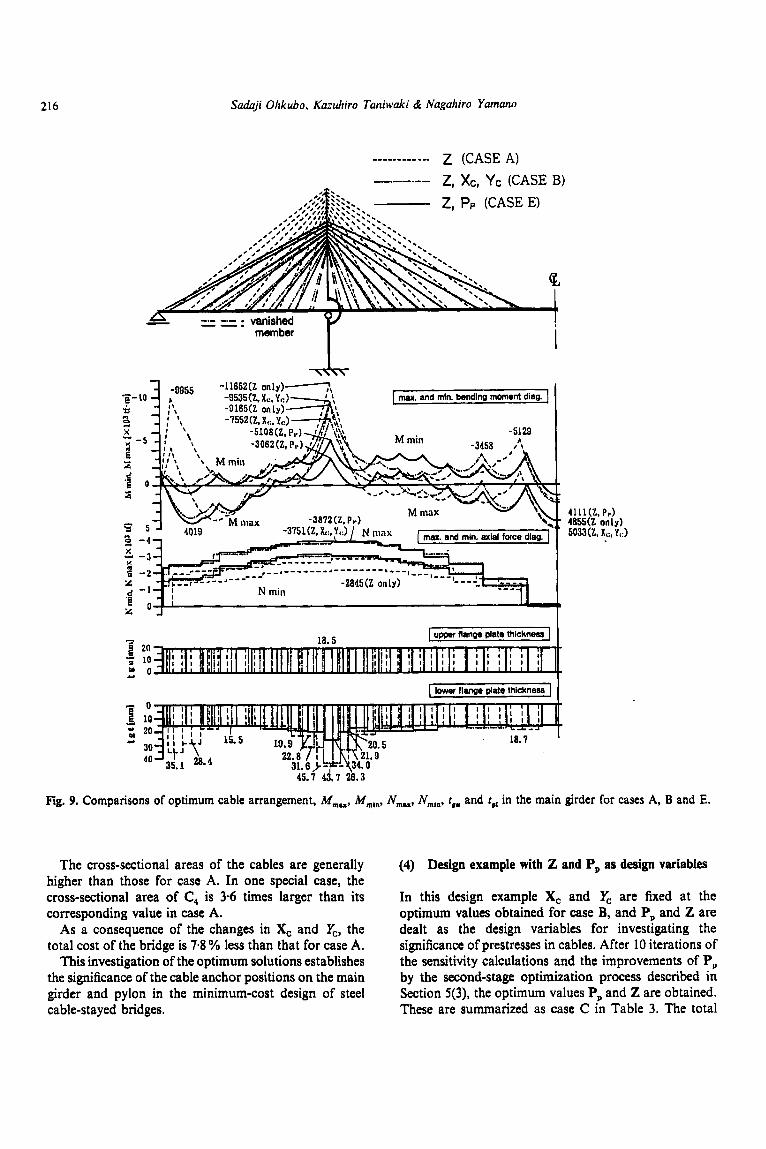
The optimum solution for the case in which Z is the only design variable is summarized as case A in Table 3, in this design example X, and U, are fixed as shown in case A. The maximum and minimum bending moments and axial force distributions, M,,, Mmin, N,,, Nmln, upper and lower flange plate thicknesses distributions, tgu, tgl, in the main girder, the distributions of M,,,, M,,,, N,,,, N,,, and the cross-sectional areas, A,, in the pylon at the optimum solution are depicted in Figs 9 and 10 by dotted lines. The bending moments and axial forces shown in Fig. 9 are those acting on one half of the cross-sectional area of the main girder depicted in Fig. 8, while the total cost expresses the cost for the whole system.
As seen from Table 3, the optimum solution is reached after six iterations and the total cost of the bridge converges to 707234.3 x lo4 yen. However, the critical local peaks, -9955 t fm near the end support and - 11 652 tf m at the middle support are observed in the
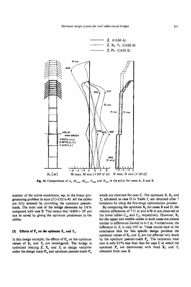
maximum or minimum bending moment distributions in the main girder. In the pylon the critical local peaks-6308 tf m and 6937 tf m occur near the top and at the main girder position, respectively.
(3) Design example with Z, X,: and Y, as design variables
The optimum solution with Z, X, and & as the design variables is summarized as case B in Table 3. The distributions of M,,,,, M,,,, N,,,, N,,,, tEU. t,, in the main girder and the distributions of M,,,,, M,,,, N,,,, Nmin and A, in the pylon at the optimum solution are depicted in Figs 9 and 10 by the chained lines. For this case, the initial values of the X(!, F., X:. and c., are assumed the same as those in case A.
In this case, the optimum solution is reached after 19 iterations. c. was assumed as 85 m ; however, its optimum value, c, is determined as 56.90 m which is 33 % lower than e.. With regard to the optimum X(,, the top two cables in the side span are seen to be parallel and are both anchored at the end support. Almost all cables, except X(.:, in the side span, are distributed in a geometric ratio. I n the center span all the cables are distributed in a geometric ratio of I : 1.3. The cross-sectional areas of the top cables in the center and side spans are much larger than those of the middle cables. The cross- sectional areas of the lowest cables in the side and center spans are found to be 0.1 cm' which is equal to the lower limit constraint and this indicates that these cables are unnecessary from a structural optimization viewpoint. It is, therefore, clear that the optimum topological cable arrangement can, also, be determined by our proposed optimum design method.
Figures 9 and 10 show that the cables are arranged so as to reduce the critical local peaks of the maximum and minimum bending moments in the main girder and pylon. The local peak of the minimum bending moment near the end support in the main girder for case A is totally absent and the local peaks of the minimum bending moment at the middle support and near the center point are reduced to 82 % and 68 %, respectively, compared with their corresponding values for case A.
At the center of the main girder, a large maximum bending moment acts on the cross section; however, the upper and lower flange plate thicknesses are determined as the same as the lower limit plate thicknesses. This means that it is not necessary to reduce the maximum bending moment at this point and this result emphasizes the reliability and rigorousness of the proposed design method. In the pylon, the maximum and minimum bending
moments are reduced to 86% and 70%, respectively, compared with the ones for case A.
Tab
le 3
C
ompa
riso
ns o
f th
e op
timum
sol
utio
ns fo
r ca
ses A
, B,
C, D
and
E
Cas
e A
B
c D
E
Load
r D
esig
n-lo
adr
Des
ign-
load
s D
esig
n-lo
ads
Des
ign-
load
s D
esig
n-lo
ads
Des
ign
vari
able
s Z
Z, x
r, Y
r z, P,
z, xc
, y,.
z, P,
Opt
imiz
atio
n pr
oces
s F
irst
-sta
ge
+ Pse
udo-
load
s + P
seud
o-lo
ads
Fir
st-s
tage
Se
cond
-sta
ge
Fir
st-s
tage
+ P
seud
o- lo
ads
Seco
nd-s
tage
140.
00
124.
00
108.
00
92.0
0 76
-00
60.00
44.0
0 28
.00
28.0
0 48
.00
68.0
0 88
-00
108.
00
128.
00
148.
53
168.
00
85.0
0 ( y
3
483 50
16
39
49
110 96 9 8 93
I02 66
10
1 75
70
289
-
1.00
14
9.00
09
2 14
3.27
0.
96
115.
48
0.99
10
3.66
0.
95
73.6
4 0.
80
:3.18
05
8 36
.16
0.30
16
.45
0.35
13
.30
0.68
?8
.01
0.86
43
.63
0.97
59
-43
1.00
80
.76
1.00
10
3:45
0-
99
133.
66
1.00
17
2.67
56.9
0 ' (
Yr)
-
432
111 47
141 96
126
116'
0'
0' 58
I09 84
82
14
0 22
7 32
8
-
1 .00
0.97
I .00
I .oo
0.94
0.
74
0.47
0.
08
0.06
03
7 06
4 0.
83
0.96
1 .00
I .oo
1 .00
-
508 40
23
163 89
96
78 0' 0'
20
I00 70
78
I70
175
350
-
982.
8 79
-3
38.5
27
3. I
170.
1 25
9.4
285.
2 0.
0 0.
0 80
5 30
0.4
143.
1 80
.3
55.2
- 46
.0
- 1
23.8
-
1.00
14
8.69
1.
00
143.
27
1.00
11
3.78
1.
00
98.2
4 1.
00
70.6
1 1.
00
48.3
6 1.
00
29.5
8 0.
03
13.6
7 0.
00
9.60
1.
00
20.7
0 1.
00
41.0
8 1.
00
60.7
3 1.
00
81.5
2 1.
00
103.
63
1.00
13
4.37
1.
00
173.
59
-
56.0
3 5
(T.)
52 1 41
25
173 89
91
70 0'
0'
18
99
78
82
I68
I89
34 I
-
1-00
51
5 I .o
o 44
1 .o
o 58
1.
00
144
I .oo
91
1 .oo
86
1 .oo
76
0.03
0'
0.
05
0'
1 .oo
9 1 .o
o 92
1 .o
o 89
1.
00
117
1.00
11
7 1.
00
197
1.00
35
2
-
-
1161
.4
101.
9 1 1
0.7
260.
3 18
0.7
247.
4 3 1
7.9
0.0
0.0
38.2
28
9.8
189.
6 13
5.7
43.7
- 6.
7 2-
5
60.9
10
.4
- 1
1.8
- 44
.3
- 26
.6
48.8
18
2.7
-0.1
0.
0 31
.3
139.
7 45
.4
- 1.
8 - 35
.8
- 49
.9
40.0
1 .oo
I .oo
I .oo
1 .oo
1 .oo
1 .oo
1 .oo
0.04
0.04
1 .oo
I .oo
1 .oo
I .oo
I .oo
I .oo
I .oo
ITEd
6
19
10
7 13
63
3218
.2 x
10'
(0.
971)
' T
CO
ST (Y
EN
) 70
7234
.3 x
lo'
(1.0
85)"
65
1 918
.9 x
10'
(1.
000)
' 63
5 10
9.9 x
10'
(0.
974)
' 63
3750
.1 x
10'
(0.9
72)'
Rat
io o
f ac
tual
tens
ile st
ress
and
allo
wab
le te
nsile
stre
ss.
Cab
le p
rest
ress
. M
inim
um c
ross
-sec
tiona
l are
a.
Num
ber
of it
erat
ions
at t
he fi
rst-s
tage
or s
econ
d-st
age o
ptim
izat
ion
proc
ess.
Rat
io o
f the
TC
OST
to th
e T
CO
ST fo
r ca
se B
.
216 Sadaji Olikubo. Kazultiro Taniwaki & Nagahiro Yamano
I member
ppperflange plate thickness 18.5
I lower I I K p l a t i thickness I
45.7 43.7 26.3
Fig. 9. Comparisons of optimum cable arrangement, M,,, M,,,,,,, N,,, Nmla, I,, and t,l in the main girder for cases A, B and E.
The cross-sectional areas of the cables are generally higher than those for case A. In one special case, the cross-sectional area of C, is 3-6 times larger than its corresponding value in case A.
As a consequence of the changes in X, and &, the total cost of the bridge is 7.8 % less than that for case A.
This investigation of the optimum solutions establishes the significance of the cable anchor positions on the main girder and pylon in the minimum-cost design of steel cable-stayed bridges.
(4) Design example with Z and P, as design variables
In this design example X, and & are fixed at the optimum values obtained for case B, and P, and Z are dealt as the design variables for investigating the significance of prestresses in cables. After 10 iterations of the sensitivity calculations and the improvements of P, by the second-stage optimization process described in Section 5(3), the optimum values P, and 2 are obtained. These are summarized as case C in Table 3. The total
Oprimuni design system for sreel cable-staj.ed bridges 217
MAIN GIRDER
- 6
z, PP (CASE E)
At [m:] M max, M min [ x 108 tf em] N max, N min [ x 10s tf]
Fig, 10. Comparisons of A, , M,,,, M,,,, N,,, and N,,, in the pylon for cases A, B and E.
number of the active constraints, mp, in the linear pro- gramming problem in eqns (51H53) is 45. All the cables are fully stressed by providing the optimum pseudo- loads. The total cost of the bridge decreases by 2.6% compared with case B. This means that 16800 x lo4 yen can be saved by giving the optimum prestresses in the cables.
(5) Effects of P, on tbe optimum X, and Y,
In this design example, the effects of P, on the optimum values of X, and & are investigated. The bridge is optimized treating Z, X, and & as design variables under the design loads P, and optimum pseudo-loads P,
which are obtained for case C. The optimum Z, X, and yC tabulated as case D in Table 3, are obtained after 7 iterations by using the first-stage optimization process.
By comparing the optimum X, for cases B and D, the relative differences of 7.31 m and 6.58 m are observed at the lower cables C,, and C,, respectively. However, X, for the upper and middle cables in both cases are almost similar to differences limited to 0-5 m. Furthermore, the difference in 6 is only 0.87 m. These results lead to the conclusion that for this specific design problem the optimum values of X, and & are not affected very much by the optimum pseudo-loads P,. The minimum total cost is only 0 2 % less than that for case C in which the optimum P, are determined with fixed X, and & obtained from case B.
218 Sadaji Ohkubo, Kaxhiro Taniwuki & Nagahiro Yariiuno
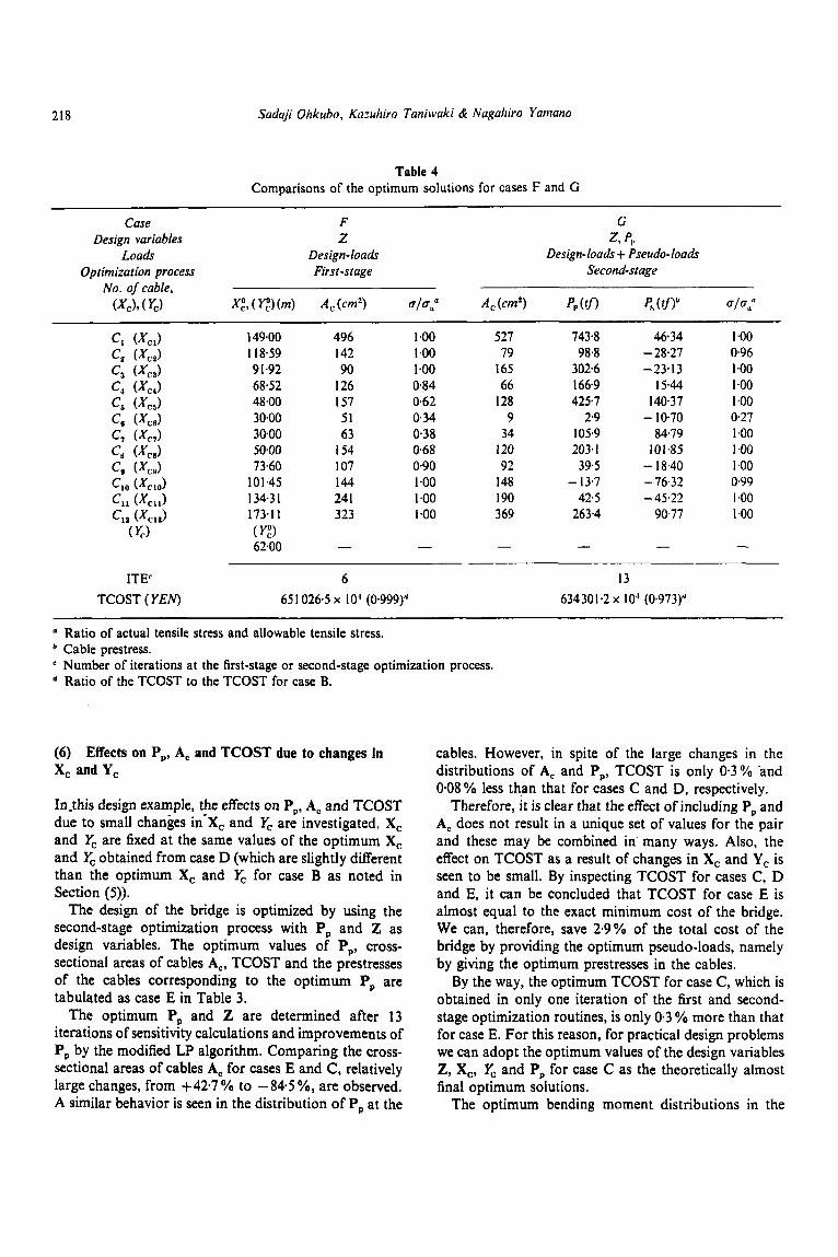
Table 4 Comparisons of the optimum solutions for cases F and G
Case F G
Loads Design-loads Design-loods + Pseudo-loads Design variables Z z, P,
Optimization process First -stage Second-stage No. of cable, (XC), ( r,) XE, ( Yt) (m) A , (cm7 ~ l ~ , ' A , (cm') pp on P, c t n b 01 0,'
c, (XCJ 149.00 496 1-00 527 7434 46.34 1 .oo
c, CXCJ 9 1.92 90 1 .oo 165 302.6 -23.13 1 .oo c4 (XCJ 68.52 I26 0.84 66 166.9 15.44 1 .oo c, (XCJ 48.00 157 0.62 128 425.7 140.37 I .oo
c, (XCJ 3000 63 0.38 34 105.9 84.79 I .oo c, (XCJ 5000 I54 068 120 203.1 101.85 1 .oo c, W C E J 73.60 I07 0.90 92 39.5 - 18.40 1 .oo
c,, ( X C J 134.3 I 24 1 1 .oo I90 42.5 -45.22 I .oo Cl, (XClJ 173.1 1 323 I -00 369 263.4 90.77 1 .oo
cz (XCJ 1 18.59 142 I ,oo 79 98.8 - 28.27 0.96
c, W C J 30.00 51 034 9 2 9 - 10.70 0.27
ClO (XCIO) 101.45 144 I .oo 148 - 13.7 - 76.32 0.99
( y,) ( y 3 - - - - - 62.00 -
ITE' 6 13 TCOST (YEN) 65 1 026.5 x 10' (0.999)'' 634301.2 x 10' (0.973)"
Ratio of actual tensile stress and allowable tensile stress. Cable prestress. Number of iterations at the first-stage or second-stage optimization process. Ratio of the TCOST to the TCOST for case B.
(6) Effects on P,, A, and TCOST due to changes in X, and Y,
In-this design example, the effects on P,, A, arid TCOST due to small changes in-X, and & are investigated. X, and & are fixed at the same values of the optimum X, and & obtained from case D (which are slightly different than the optimum X, and & for case B as noted in Section (5)) .
The design of the bridge is optimized by using the second-stage optimization process with P, and Z as design variables. The optimum values of P,, cross- sectional areas of cables A,, TCOST and the prestresses of the cables corresponding to the optimum P, are tabulated as case E in Table 3.
The optimum P, and Z are determined after 13 iterations of sensitivity calculations and improvements of P, by the modified LP algorithm. Comparing the cross- sectional areas of cables A, for cases E and C, relatively large changes, from +42.7 % to -84.5 %, are observed. A similar behavior is seen in the distribution of P, at the
cables. However, in spite of the large changes in the distributions of A, and P,, TCOST is only 0.3% .and 0.08 % less than that for cases C and D, respectively.
Therefore, i t is clear that the effect of including P, and A, does not result in a unique set of values for the pair and these may be combined in' many ways. Also, the effect on TCOST as a result of changes in X, and Y, is seen to be small. By inspecting TCOST for cases C, D and E, it can be concluded that TCOST for case E is almost equal to the exact minimum cost of the bridge. We can, therefore, save 2.9% of the total cost of the bridge by providing the optimum pseudo-loads, namely by giving the optimum prestresses in the cables.
By the way, the optimum TCOST for case C, which is obtained in only one iteration of the first and second- stage optimization routines, is only 0.3 YO more than that for case E. For this reason, for practical design problems we can adopt the optimum values of the design variables 2, X,, & and P, for case C as the theoretically almost final optimum solutions.
The optimum bending moment distributions in the
Optimum design .y-stem j i ir steel cable-staved bridges 219
-10 - E i: z 5 -5
2
'ii
- 5 4924(Z only) ," -a
may. and min. bending moment diag.
0
x
z c ' o
z 3370(Z. Pa-)
0 X
-2
.. I f f s 1 upper flange plate thickness 1 I --. - 20 10 0 I I I1111111 I I I 1 1 1 1 I I I I I I 1 1 1 :
I I [ lower flange plate thickneso
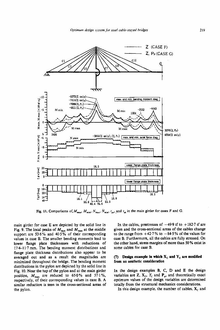
Fig. 11. Comparisons of.M,,, Mmm, N,,, NmI,, tY,,and t, in the main girder for cases F and G.
main girder for case E are depicted by the solid line in Fig. 9. The local peaks of Mmln and M,,, at the middle support are 53.6% and 405% of their corresponding values in case B. The smaller bending moments lead to lower flange plate thicknesses with reductions of 174-1 1.7 mm. The bending moment distributions and flange plate thickness distributions also appear to be averaged out and as a result the magnitudes are minimized throughout the bridge. The bending moment distributions in the pylon are depicted by the solid line in Fig. 10. Near the top of the pylon and at the main girder position, M,,, are reduced to 65.0% and 57.1 %, respectively, of their corresponding values in case B. A similar reduction is seen in the cross-sectional areas of the pylon.
In the cables, prestresses of -49-9 tf to + 182-7 tf are given and the cross-sectional areas of the cables change to the range from +42*7 % to - 84.5 % of the values for case B. Furthermore, all the cables are fully stressed. On the other hand, stress margins of more than 50 % exist in some cables for case B.
(7) Design example in which X, and Y, are modified from an aesthetic consideration
In the design examples By C, D and E the design variables are Z, X,, & and P,, and theoretically exact optimum values of the design variables are determined totally from the structural mechanics considerations.
In this design example, the number of cables, X, and
220 Sadaji Ohkubo, Karuhiro Taniwaki & Nagahiro Yamano
-
AXIS OF MAIN GIRDER
0.6234CL only) 0.5149(2. PI,)
- 6 - 4 - 2 0 2 4 6
N max
LLL 4 - 2
At [mz] M rnax, M niin [ x lo:! tf * in] N iiiax, N iiiiii [ x 103 tf]
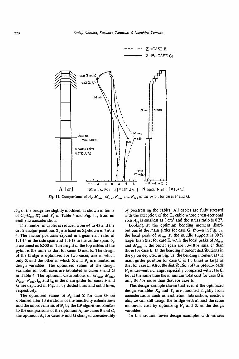
Fig. 12. Comparisons of A,, M,,,, M,,,, N,,, and N,,, in the pylon for cases F and G .
. Y, of the bridge are slightly modified, as shown in terms of C1-Cla, XO, and y", in Table 4 and Fig. 11 , from an aesthetic consideration.
The number of cables is reduced from 64 to 48 and the cable anchor positions X, are fixed as XO, shown in Table 4. The anchor positions expand in a geometric ratio of 1 : 1.14 in the side span and 1 : 1.18 in the center span. & is assumed as 62.00 m. The height of the top cables at the pylon is the same as that for cases D and E. The design of the bridge is optimized for two cases, one in which only Z and the other in which Z and P, are treated as design variables. The optimized values of the design variables for both cases are tabulated as cases F and G in Table 4. The optimum distributions of M,,,,,, M,,,,, N,,,, NmIn, t,, and tg, in the main girder for cases F and G are depicted in Fig. 11 by dotted lines and solid lines, respectively.
The optimized values of P, and Z for case G are obtained after 13 iterations of the sensitivity calculations and the improvements of P, by the LP algorithm. Similar to the comparisons of the optimum A, for cases B and C, the optimum A, for cases F and G changed considerably
by prestressing the cables. All cables are fully stressed with the exception of the C, cable whose cross-sectional area A,, is smallest as 9 cma and the stress ratio is 0.27.
Looking at the Optimum bending moment distri- butions in the main girder for case G, shown in Fig. 11, the local peak of AdmI,, at the middle support is 39% larger than that for case E, while the local peaks of M,,, and MmIn in the center span are 13-18% smaller than those for case E. In the bending moment distributions in the pylon depicted in Fig. 12, the bending moment at the main girder position for case G is 1.6 times as large as that for case E. Also, the distribution of the pseudo-loads P, underwent a change, especially compared with case E, but at the same time the minimum total cost for case G is only 0.17% more than that for case E.
This design example shows that even if the optimized design variables X, and yC are modified slightly from considerations such as aesthetics, fabrication, erection etc., we can still design the bridge with almost the same minimum cost by optimizing P, and Z as the design variables.
In this section, seven design examples with various
Optimum design system for steel cable-stuyerl bridges 22 1
design conditions were described. From the investigation of their optimum solutions, it is clear that the proposed optimum design algorithm can determine the cable prestresses besides the cross-sectional dimensions, such as upper and lower flange plate thicknesses of each member element in the main girder and pylon, cross- sectional areas of the cables and cable anchor positions, etc. quite rigorously and efficiently. We can, therefore, conclude that the proposed optimum design system is quite useful for practical design of the steel cable-stayed bridge at all design stages, from the planning stage to the detailed design stage.
8 CONCLUSIONS
The conclusions that can be drawn from this study are:
(1) The global optimum solutions of steel cable-stayed bridges for various design conditions and com- binations of the design variables Z, X,, Y, and P, can be determined quite rigorously and efficiently by the proposed two-stage optimum design method.
(2) The optimum values of pylon height, cable anchor positions, steel plate thicknesses of the main girder and pylon and cross-sectional area of each cable appear to be reasonable and well balanced.
(3) The total cost of steel cable-stayed bridge is greatly affected by the cable anchor positions on the main girder and pylon. Therefore, the cable anchor positions and the height of the pylon need to be included in the set of design variables.
(4) From structural mechanics considerations, with regard to the optimum cable arrangement in the design examples, the top two cables in the side span are seen to be parallel and are both anchored at the end suppcfrt. In the center span all the cables are distributed as the geometric ratio. The cross- sectional areas of the top cables in side and center spans are much larger than those of the middle cables. The cross-sectional areas of the unnecess-
. ary cables at the optimum solution are found to be the imposed lower limit automatically by the proposed optimum design method.
(5) By giving the optimum prestresses to the cables, the local peaks of minimum and maximum bending moment at the middle support in the main girder are reduced to 53.6403% and the cross- sectional areas of cables change from + 42.7 YO to
-84.5%. and all nontrivial cables are fully stressed. A reduction of 2.9% in the total cost of the bridge is observed by giving the optimum cable prestresses in the design examples.
(6 ) The proposed optimum design system is quite useful for practical design of the steel cable-stayed bridge at all design stages, such as from the planning stage to the detailed design stage.
REFERENCES
I . Fleury, C. & Braibant, V., Structural optimization : A new dual method using mixed variables. Int. J . Numer. Meth. Engng, 23 (1986) 409-28.
2. Gimsing, N. J., Cable Supported Bridges, Concept und Design, John Wiley & Sons, Chichester, New York. 1983.
3. Hoshino, M., A method to determine cable prestresses of cable-stayed bridges. Proc. JSCE, 374 (1-6) (1986) 487-94 (in Japanese).
4. Japan Road Association, Specifications for Highway Bridges, Steel Bridges, Maruzen Co. Ltd, Tokyo, 1980 (in Japanese).
5. Kobayashi, I., Miike, R.. Sasaki. T. & Otsuka, H., Multilevel optimal design of cable-stayed bridges with various types of anchorages. Proc. JSCE, 392 (1-9) (1988) 3 17-25 (in Japanese).
6. Nakamura, S. & Wyatt, T. A.. A parametric study on cable-stayed bridges by the limit states design. Proc. JSCE,
7. Ohkubo, S. & Asai, K., A hybrid optimal synthesis method for truss structures considering shape, material and sizing variables. Int. J . Numer. Meth. Engng. 34 (1992) 839-51
8. Ohkubo, S. & Taniwaki, K., Optimization of cable arrangement and element sizes of steel cable-stayed bridges. Proc. JSCE, 428 (1-15) (1991) 147-56 (in Japanese).
9. Ohkubo, S. & Taniwaki, K.. Shape and sizing optimization of steel cable-stayed bridges. In Optimization. of Structural Systems and Industrial Applications. Elsevier Applied Science, London, New York, 1991, pp. 529-40.
10. Prasad, B., Explicit constraint approximation forms in structural optimization-Part I : Analyses and projections. Comp. Meth. Appl. Mech. Engng, 40 (1983) 1-26.
11. Starnes, J. H. & Haftka, R. T., Preliminary design of composite wings for buckling, strength, and displacement constraints. J. Aircraft, 16 (8) (1979) 564-70.
12. Yamada, Y. & Daiguji, H., Optimum design of cable- stayed bridges using optimality criteria. Proc. JSCE, 253 (1976) 1-12 (in Japanese).
13. Yamada, Y., Furukawa, K., Egusa, T. & Inoue, K., Studies on optimization of cable prestresses of cable-stayed bridges. Proc. JSCE, 356 (1-3) (1985) 41 5-23 (in Japanese).
398 (1-10) (1988) 61-9.


![[TECH]Cable Stayed Bridges](https://img.pdfslide.us/doc/110x75/544cd985b1af9f3a0b8b4c5b/techcable-stayed-bridges.jpg)