Embed Size (px)
Citation preview

© 2018 JETIR December 2018, Volume 5, Issue 12 www.jetir.org (ISSN-2349-5162)
JETIR1812B62 Journal of Emerging Technologies and Innovative Research (JETIR) www.jetir.org 487
OPTIMIZING THE PROCESS PARAMETERS OF
EDM USING TAGUCHI METHOD AND ANOVA
ON INCONEL 718
Puttur Neelakantam Vani1 , K. Arun2 , Dr. M. Chandra Sekhara Reddy3, M.Madduleti4
1, 2, 3 Department of Mechanical Engineering, SVCE, Tirupati, 4 Ph.D scholar, Svu college of Engg , Tirupati , India.
ABSTRACT
Wire Electro - Discharge Machining (EDM) is a metal-working process whereby material is removed from a
conductive work piece by electrical erosion. This project work focuses on finding out the optimum parameters in Wire
- EDM for machining of Inconnel 718. The major application of the Inconnel material is in the aerospace industry,
both in airframes and engine components. Biocompatibility of Inconnel is excellent, especially when direct contact
with tissue or bone is required.
Input process parameters that are taken into consideration are wire feed rate, Pulse on time, Pulse off time,
Peak current, and Servo voltage. Output parameters are Material removal rate (MRR), Kerf width and Surface
roughness (SR) are measured. Also different wire materials like Half Hard Brass wire, Zn-Coated Brass wires are
used in this experiment.
For design of experiment Taguchi methodology of L18 orthogonal array is used. From the experiment, it can
be conclude that Zn-Coated Brass wire is desirable for maximum MRR and minimum SR with good surface integrity,
but Half Hard Brass wire is desirable for minimum Kerf width. An excellent combination of better flush ability, high
mechanical strength and good electrical conductivity are the advantages of Zn-Coated Brass wires in contrast to Half
Hard Brass wire.
Key words : wire feed rate, Pulse on time, Pulse off time, Peak current, and Servo voltage. Material removal
rate (MRR), Kerf width and Surface roughness (SR).
1.INTRODUCTION
1. Electrical Discharge Machining (EDM)
Electrical Discharge Machine (EDM) is now
become the most important accepted technologies
in manufacturing industries since many complex
3D shapes can be machined using a simple shaped
tool electrode. Electrical discharge machine (EDM)
is an important „non-traditional manufacturing
method‟, developed in the late 1940s and has been
accepted worldwide as a standard processing
manufacture of forming tools to produce plastics
moldings, die castings, forging dies and etc.
Major development of EDM was observed when
computer numerical control systems were applied
for the machine tool industry. Thus, the EDM
process became automatic and unattended
machining method. At the present time, Electrical
discharge machine (EDM) is a widespread
technique used in industry for high precision
machining of all types of conductive materials such
as: metals, metallic alloys, graphite, or even some
ceramic materials, of whatever hardness.
1.2 Wire Electrical Discharge Machining (WEDM)
The world‟s first WEDM was produced by the
SWISS FIRM „AGIE‟ in 1969. The first WEDM
machine worked simply without any complication
and wire choices were limited to copper and brass
only. Several researches were done on early
WEDM to modify its cutting speed and overall
capabilities. In recent decades, many attempts were
done on Wire EDM technology in order to satisfy
various manufacturing requirements, especially in
the precision mold and die industry. Wire EDM
efficiency and productivity have been improved
through progress in different aspects of WEDM
such as quality, accuracy, and precision .
1 .3 Principle of Wire - EDM
The Spark Theory on a wire EDM is basically the
same as that of the vertical EDM process. In wire
EDM, the conductive materials are machined with
a series of electrical discharges (sparks) that are
produced between an accurately positioned moving
wire (the electrode) and the work piece. High
frequency pulses of alternating or direct current is
© 2018 JETIR December 2018, Volume 5, Issue 12 www.jetir.org (ISSN-2349-5162)
JETIR1812B62 Journal of Emerging Technologies and Innovative Research (JETIR) www.jetir.org 488
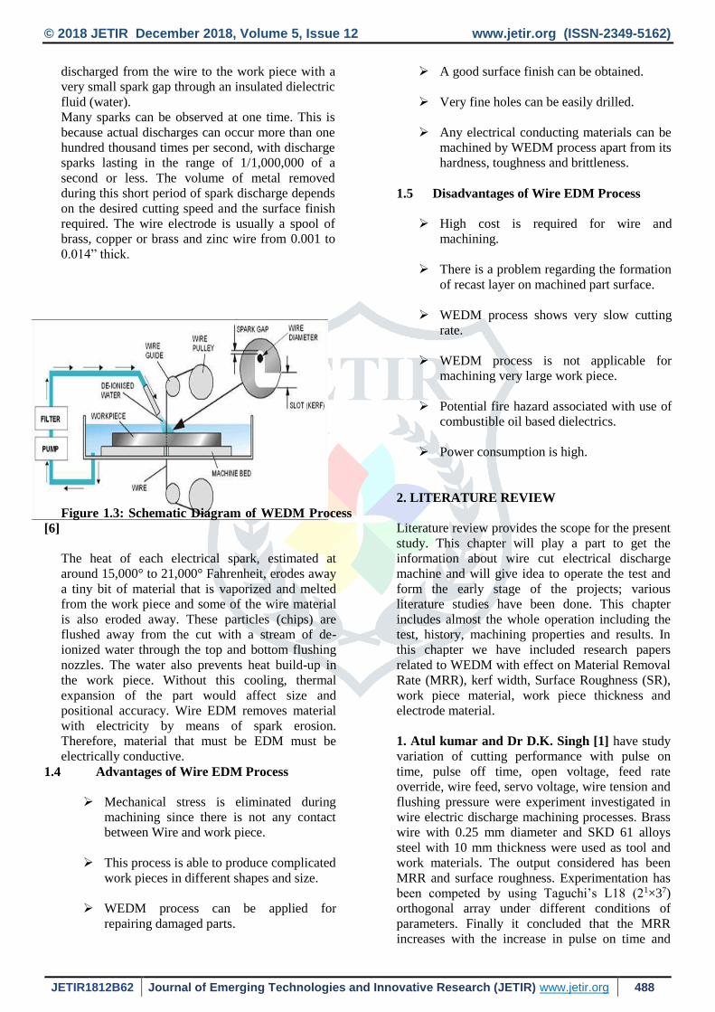
discharged from the wire to the work piece with a
very small spark gap through an insulated dielectric
fluid (water).
Many sparks can be observed at one time. This is
because actual discharges can occur more than one
hundred thousand times per second, with discharge
sparks lasting in the range of 1/1,000,000 of a
second or less. The volume of metal removed
during this short period of spark discharge depends
on the desired cutting speed and the surface finish
required. The wire electrode is usually a spool of
brass, copper or brass and zinc wire from 0.001 to
0.014” thick.
Figure 1.3: Schematic Diagram of WEDM Process
[6]
The heat of each electrical spark, estimated at
around 15,000° to 21,000° Fahrenheit, erodes away
a tiny bit of material that is vaporized and melted
from the work piece and some of the wire material
is also eroded away. These particles (chips) are
flushed away from the cut with a stream of de-
ionized water through the top and bottom flushing
nozzles. The water also prevents heat build-up in
the work piece. Without this cooling, thermal
expansion of the part would affect size and
positional accuracy. Wire EDM removes material
with electricity by means of spark erosion.
Therefore, material that must be EDM must be
electrically conductive.
1.4 Advantages of Wire EDM Process
Mechanical stress is eliminated during
machining since there is not any contact
between Wire and work piece.
This process is able to produce complicated
work pieces in different shapes and size.
WEDM process can be applied for
repairing damaged parts.
A good surface finish can be obtained.
Very fine holes can be easily drilled.
Any electrical conducting materials can be
machined by WEDM process apart from its
hardness, toughness and brittleness.
1.5 Disadvantages of Wire EDM Process
High cost is required for wire and
machining.
There is a problem regarding the formation
of recast layer on machined part surface.
WEDM process shows very slow cutting
rate.
WEDM process is not applicable for
machining very large work piece.
Potential fire hazard associated with use of
combustible oil based dielectrics.
Power consumption is high.
2. LITERATURE REVIEW
Literature review provides the scope for the present
study. This chapter will play a part to get the
information about wire cut electrical discharge
machine and will give idea to operate the test and
form the early stage of the projects; various
literature studies have been done. This chapter
includes almost the whole operation including the
test, history, machining properties and results. In
this chapter we have included research papers
related to WEDM with effect on Material Removal
Rate (MRR), kerf width, Surface Roughness (SR),
work piece material, work piece thickness and
electrode material.
1. Atul kumar and Dr D.K. Singh [1] have study
variation of cutting performance with pulse on
time, pulse off time, open voltage, feed rate
override, wire feed, servo voltage, wire tension and
flushing pressure were experiment investigated in
wire electric discharge machining processes. Brass
wire with 0.25 mm diameter and SKD 61 alloys
steel with 10 mm thickness were used as tool and
work materials. The output considered has been
MRR and surface roughness. Experimentation has
been competed by using Taguchi’s L18 (21×37)
orthogonal array under different conditions of
parameters. Finally it concluded that the MRR
increases with the increase in pulse on time and

© 2018 JETIR December 2018, Volume 5, Issue 12 www.jetir.org (ISSN-2349-5162)
JETIR1812B62 Journal of Emerging Technologies and Innovative Research (JETIR) www.jetir.org 489
decrease with increase in pulse off time and open
voltage. The effect of feed rate overdrive, wire
feed, servo voltage, wire tension and flushing
pressure on MRR is not very significant. For the
surface roughness it decrease with increase of pulse
off time open voltage and wire feed and increases
with increase in feed rate override and servo
voltage. The effect of other parameter is not
significant.
2. Pujari Srinivasa Rao, Koona Ramji, Beela
Satyanarayana [2] studied Wire-cut electric
discharge machining of Aluminum-24345.
Experimentation has been done by using Taguchi’s
L18 (21x37) orthogonal array under different
conditions of parameters. The response of surface
roughness is considered for improving the
machining efficiency. Optimal combinations of
parameters were obtained by this method. The
confirmation experiment shows, the significant
improvement in surface finish (1.03μm) was
obtained with this method. The study shows that
with the minimum number of experiments the
stated problem can be solved when compared to
full factorial design. All the experiments were
conducted on Ultra Cut 843/ ULTRA CUT f2 CNC
Wire-cut EDM machine.
3. Kuriachen Basil, Dr. Josephkunju Paul, Dr.
Jeoju M.Issac [3] investigates the effect of
voltage, dielectric pressure, pulse on-time and pulse
off-time on spark gap of Ti6AL4V alloy. It has
been found that pulse on time and pulse off time
have the more impact on the spark gap. The
minimum spark gap was obtained as 0.040407mm.
The WEDM experiments were conducted in
Electronic Ultracut S1 machine using 0.25 mm
brass wire as the tool electrode. Pulse on time,
pulse off time, voltage and dielectric pressure are
the four WEDM parameters that were selected for
investigations. In this experimental study two level
full factorial experiment is adopted because this
gives all possible combinations of machine
parameters. It can be noticed from that
corresponding to minimum value of pulse off time
the spark gap decreases with increase in dielectric
pressure, whereas the spark gap increases with
increase in dielectric pressure corresponding to
maximum value of pulse off time.
4.Saurav Datta, Siba Sankar Mahapatra [4]
experimented with six process parameters are
discharge current, pulse duration, pulse frequency,
wire speed, wire tension and dielectric flow rate; to
be varied in three different levels.
mm Predicted data given by the models as per
Taguchi’s L18 (3*6) Orthogonal Array (OA)
design have been used in search of an optimal
parametric combination to achieve desired yield of
the process, maximum MRR, good surface finish
and dimensional accuracy of the product. Grey
relational analysis has been adopted to convert this
multi-objective criterion into an equivalent single
objective function. It has been found that that the
spark gap increases with increase in pulse on time,
whereas spark gap decreases with increase in pulse
off time. The pulse on time, pulse off time, the
interaction of dielectric pressure and pulse off time,
and interaction of pulse on time and pulse off time
are significant parameters which affect the spark
gap of WEDM.
5. Nihat, Can, Gul [5] investigated on the effect
and optimization of machining parameters on kerf
and material removal rate (MRR) in WEDM
operations. Experimental studies were conducted
using different pulse duration, open circuit voltage,
wire speed, and dielectric flushing pressure.
Importance levels of parameters were analysed
using analysis of variance (ANOVA). The
optimum machining parameter combination was
obtained by using the analysis of signal-to-nois
(S/N) ratio. The variation of kerf and MRR with
machining parameters is mathematically modelled
by using regression analysis method. Objective of
minimum kerf together with maximum MRR was
performed. The experimental studies were
performed on a Sodick A320D/EX21 WEDM
machine tool. CuZn37 Master Brass wire with
0.25mm diameter was used in the experiments. As
work piece material, AISI 4140 steel with 200mm
× 40mm × 10mm size was used. The results show
that open circuit voltage was three times more
important than pulse duration for controlling kerf,
while for MRR, open circuit voltage was about six
times more important than pulse duration.
6. Mustafa Ilhan et al. [6] aims to select the most
suitable parameter combination for the wire
electrical discharge machining process in order to
get the desired surface roughness value for the
machined work pieces. A series of experiments
have been performed on 1040 steel material of
thicknesses 30, 60 and 80 mm, and on 2379 and
2738 steel materials of thicknesses 30 and 60 mm.
The test specimens have been cut by using different
cutting and offset parameter combinations of the
“Sodick Mark XI A500 EDW” wire electrical
discharge machine. The related tables and charts
have been prepared for 1040, 2379, 2738 steel
materials. The tables and charts can be practically
used for WEDM parameter selection for the desired
work piece surface roughness. And finding out that
increasing work piece thickness more stable &
better SR characteristics.
7. G.Rajyalakshmi, Dr.P.Venkata Ramaiah [7]
presented experiments with eight process
parameters: pulse on time, pulse off time, corner
servo voltage, wire feed, wire tension, dielectric
flow rate, spark gap voltage and servo feed to be
varied in three different levels. Data related to the

© 2018 JETIR December 2018, Volume 5, Issue 12 www.jetir.org (ISSN-2349-5162)
JETIR1812B62 Journal of Emerging Technologies and Innovative Research (JETIR) www.jetir.org 490
process response is SR which corresponds to
randomly chosen different combinations of factor
setting. The electrode material used was a 0.25 mm
diameter brass wire. A small gap of 0.025 mm to
0.05 mm is maintained in between the wire and
work-piece. Inconel825 is used as work piece
material. Pulse on time and wire feed rate have
been most significant effect on SR.
8. Chiang et al [8]. have been investigated on
“Optimization of the WEDM process of particle-
reinforced material with multiple performance
characteristics using grey relational analysis”
employed grey relational analysis to optimize the
input parameters are pulse on time, pulse off time,
arc on time, arc off time, servo voltage, wire feed
and water flow are optimized parameters for Al2O3
particle reinforced material with two response
parameters are material removal rate and surface
roughness. It have concluded the response table and
response graph for each level of the machining
parameters are obtained from the grey relational
grade, and select the optimal levels of machining
parameters.
3.DESIGN OF EXPERIMENT
WEDM Process Parameters
The process parameters that can affect the
quality of machining or cutting or drilling in
Wire EDM process are shown through
Ishikawa cause – effect diagram as shown in
Figure 3.1.
The major parameters are as follows:-
Electrical parameters: Peak current,
pulse on time, pulse off time, supply
voltage and polarity.
Non – electrical parameters: wire
speed; work feed rate, machining time,
gain and rate of flushing.
Electrode based parameters: Material
and size of wire.
Figure 3.1: Process Parameters and Performance
Measures of WEDM
3.1 Wire Cut Electro Discharge Machine [WEDM]
This experimental work performed at Shubham
wire cut, Odhav, Ahmedabad. The experiment work is
carried out in sprintcut wire cut electro discharge
machine (ELEKTRONICA SPRINTCUT 734) of
Inconnel 718 material by varying machining
parameters.
The sprintcut wire cut electric discharge machine is
consist of a machine tool, a power supply unit and
dielectric supply unit. A schematic diagram of the
sprintcut wire cut EDM is shown in Figure 4.1.
Figure 3.1: Sprintcut Wire Cut EDM.
Table No 3.1: Final Measurement Data (Half Hard
Brass wire (0.25mm))

© 2018 JETIR December 2018, Volume 5, Issue 12 www.jetir.org (ISSN-2349-5162)
JETIR1812B62 Journal of Emerging Technologies and Innovative Research (JETIR) www.jetir.org 491
3.2 Results of Zn-Coated Brass wire (0.25mm)
4.Analysis of Variance (ANOVA) ANOVA is a standard statistical technique to interpret the
experimental results. The percentage contribution of various
process parameters to the selected performance characteristic
can be estimated by ANOVA. Thus information about how
significant the effect of each controlled parameter is on the
quality characteristic of interest can be obtained. ANOVAs
for raw data has been performed to identify the significant
parameters and to quantify their effect on the performance
characteristic. The ANOVA based on the raw data identifies
the factors which affect the average response rather than
reducing variation.
ANOVA helps in formally testing the significance
of all main factors and their interactions by
comparing the mean square against an estimate of
the experimental errors at specific confidence
levels. Study of ANOVA table for a given analysis
helps to determine which of the factors need
control and which do not. Once the optimum
condition is determined, it is usually good practice
to run a confirmation experiment. The analysis of
the partial experiment must include an analysis of
confidence that can be placed in the results. So
analysis of variance is used to provide a measure of
confidence.
First the formula finding for the Pure Sum of
Square (SS’) is given below:
SS’= Seq SS – DF * (Adj MS Error)
And the Percentage Contribution formula is
given below:
Percentage contribution = (SS’/ Total Seq. SS)
* 100% Percentage contribution of input
Sr. WF Ton Toff Ip SV MRR KERF SR
No.
(m/mi
n) (µs) (µs) (Amp) (Volt)
(mm2/mi
n) (mm) (µm)
1 6 110 50 120 15 15.20 0.2908 2.5569
2 6 110 55 140 20 14.90 0.2989 2.5011
3 6 110 60 160 25 8.92 0.3102 2.4235
4 6 115 50 120 20 23.76 0.3086 2.8834
5 6 115 55 140 25 19.80 0.3179 3.1024
6 6 115 60 160 15 21.14 0.2788 3.2561
7 6 120 50 140 15 28.91 0.3385 3.7236
8 6 120 55 160 20 29.80 0.3028 3.3842
9 6 120 60 120 25 20.08 0.2739 2.8923
10 8 110 50 160 25 18.80 0.2633 2.3908
11 8 110 55 120 15 16.90 0.1934 2.4198
12 8 110 60 140 20 14.20 0.2031 2.1600
13 8 115 50 140 25 25.20 0.2897 2.9785
14 8 115 55 160 15 26.84 0.2332 3.4236
15 8 115 60 120 20 18.00 0.1989 2.6039
16 8 120 50 160 20 31.60 0.3310 3.5139
17 8 120 55 120 25 29.10 0.2697 3.0667
18 8 120 60 140 15 27.60 0.2381 3.1522
No.
WF
(m/mi
n)
Ton
(µs)
Toff
(µs)
Ip
(Am
p)
SV
(Volt
)
MRR
(mm2/
min)
KERF
(mm)
SR
(µm)
1 6 110 50 120 15 22.12 0.3178 2.2702
2 6 110 55 140 20 17.70 0.3296 2.2372
3 6 110 60 160 25 16.22 0.3584 2.1223
4 6 115 50 120 20 27.80 0.3714 2.7865
5 6 115 55 140 25 25.80 0.3602 2.6851
6 6 115 60 160 15 27.08 0.3489 2.5604
7 6 120 50 140 15 38.04 0.3642 2.9653
8 6 120 55 160 20 33.08 0.3789 2.8116
9 6 120 60 120 25 26.33 0.3447 2.2608
10 8 110 50 160 25 23.08 0.3322 2.2992
11 8 110 55 120 15 19.80 0.2842 2.1893
12 8 110 60 140 20 18.10 0.2983 1.8632
13 8 115 50 140 25 31.50 0.3463 2.5792
14 8 115 55 160 15 32.12 0.3207 2.7323
15 8 115 60 120 20 21.80 0.3144 2.3725
16 8 120 50 160 20 37.58 0.3519 2.9865
17 8 120 55 120 25 32.75 0.3315 2.6012
18 8 120 60 140 15 36.44 0.3088 2.498
Source DF Seq SS Adj SS
Adj
MS F P
%
Contrib
ution
WF
(m/min) 1 36.78 36.780 36.78 19.54 0.002 4.93
Ton (µs) 2 514.25 514.25 257.1 136.6 0.000 72.12
Toff (µs) 2 106.25 106.25 53.12 28.23 0.000 14.48
Ip (Amp) 2 16.506 16.506 8.253 4.39 0.052 1.80
Sv (Volt) 2 18.993 18.99 9.497 5.05 0.038 2.15
Error 8 15.056 15.05 1.882 4.52
Total 17 707.84 100

© 2018 JETIR December 2018, Volume 5, Issue 12 www.jetir.org (ISSN-2349-5162)
JETIR1812B62 Journal of Emerging Technologies and Innovative Research (JETIR) www.jetir.org 492
parameters to outputs MRR, Kerf width, and
Surface Roughness
4.1 ANOVA for MRR (Half Hard Brass
Wire (0.25mm))
In this research work, ANOVA Table for
MRR Half Hard Brass wire (0.25mm) is
shown in Table 5.15
Calculation of SS’ and Percentage Contribution of
MRR for Half Hard Brass wire.
1) Pure Sum of Square (SS’) - For WF SS’:
36.780 – (1*1.882)
36.780 – 1.882
34.898
For Ton SS’:
514.252 – (2*1.882)
514.252 – 3.764
510.488
For Toff SS’:
106.255 – (2*1.882)
106.255 – 3.764
102.491
For Ip SS’:
16.506 – (2*1.882)
16.506 – 3.764
12.742
For SV SS’:
18.993 – (2*1.882)
18.993 – 3.764
15.229
Percentage Contribution - For WF Percentage Contribution:
2) WEDM on Inconnel 718 for Material
removal rate for Half Hard Brass Wire. The
percentage contribution of Wire feed rate is
4.93%, Pulse on time is 72.12%, Pulse off time is
14.48%, Peak current is 1.80%, Servo voltage is
2.15%, and error is 4.52%. This error is due to
machine vibration.
3)
4) Percentage Contribution -
For WF Percentage Contribution:
=34.898/707.842* 100%
=4.93 %
For Ton Percentage Contribution:
=510.488/707.842* 100%
=72.12 %
For Toff Percentage Contribution:
=102.491/707.842* 100%
=14.48 %
For Ip Percentage Contribution:
=12.742/707.842* 100%
=1.80 %
For SV Percentage Contribution:
=15.229/707.842* 100%\
=2.15 %
Above analysis shows the percentage contribution of
individual process input parameters of WEDM on
Inconnel 718 for Material removal rate for Half Hard
Brass Wire. The percentage contribution of Wire feed
rate is 4.93%, Pulse on time is 72.12%, Pulse off time
is 14.48%, Peak current is 1.80%, Servo voltage is
2.15%, and error is 4.52%. This error is due to
machine vibration.
ANOVA for Kerf Width (Half Hard Brass wire
(0.25mm))
4.2ANOVA Table for Kerf Width for Half Hard
Brass wire (0.25mm)
Percentage Contribution - For WF Percentage Contribution:
=0.013500/0.0340906* 100%
=39.60 %
For Ton Percentage Contribution:
=0.002467/0.0340906* 100%
=7.23 %
For Toff Percentage Contribution:
Source DF Seq SS Adj SS Adj MS F P
Percentage
Contributio
n
WF
(m/min) 1 0.0138889 0.0138889 0.0138889 35.74 0.000 39.60
Ton (µs) 2 0.0032444 0.0032444 0.0016222 4.17 0.057 7.23
Toff (µs) 2 0.0087155 0.0087155 0.0043578 11.21 0.005 23.29
Ip
(Amp) 2 0.0032068 0.0032068 0.0016034 4.13 0.059 7.13
Sv
(Volt) 2 0.0019261 0.0019261 0.0009631 2.48 0.145 3.37
Error 8 0.0031089 0.0031089 0.0003886
19.38
Total 17 0.03409
100

© 2018 JETIR December 2018, Volume 5, Issue 12 www.jetir.org (ISSN-2349-5162)
JETIR1812B62 Journal of Emerging Technologies and Innovative Research (JETIR) www.jetir.org 493
=0.007938/0.0340906* 100%
=23.29 %
For Ip Percentage Contribution:
=0.0024296/0.0340906* 100%
=7.13 %
For SV Percentage Contribution:
=0.0011489/0.0340906* 100%
=3.37 %
Above analysis shows the percentage contribution of
individual process input parameters of WEDM on
Inconnel 718 for Kerf Width for Half Hard Brass
Wire. The percentage contribution of Wire feed rate is
39.60%, Pulse on time is 7.23%, Pulse off time is
23.29%, Peak current is 7.13%, Servo voltage is
3.37%, and error is 19.38%. This error is due to
machine vibration.
ANOVA for Surface Roughness (Half Hard Brass
wire (0.25mm))
In this research work, ANOVA Table for Surface
Roughness for Half Hard Brass wire (0.25mm) is
shown in Table
Table ANOVA for Surface Roughness (Half Hard
Brass wire (0.25mm))
• Percentage Contribution -
– For WF Percentage Contribution:
– 0.04834/3.45549*
100%
– 1.40 %
– For Ton Percentage Contribution:
– 2.45465/3.45549*
100%
– 71.04 %
– For Toff Percentage Contribution:
– 0.22912/3.45549*
100%
– 6.63 %
– For Ip Percentage Contribution:
– 0.31044/3.45549*
100%
– 8.98 %
– For SV Percentage Contribution:
– 0.26353/3.45549*
100%
– 7.63 %
•
Above analysis shows the percentage
contribution of individual process input parameters of
WEDM on Inconnel 718 for Surface Roughness for
Half Hard Brass Wire. The percentage contribution of
Wire feed rate is 1.40%, Pulse on time is 71.04%,
Pulse off time is 6.63%, Peak current is 8.98%, Servo
voltage is 7.63%, and error is 4.32%. This error is due
to machine vibration.
5.RESULTS
ANOVA analysis result for the Half Hard Brass
wire on Material Removal Rate, percentage
contribution of wire feed 4.93%, pulse on time is
72.12%, pulse off time 14.48%, peak current is 1.80%,
and servo voltage is 2.15%. The optimal level
combination factor for MRR in Half Hard Brass wire
is 30m/min for Wire feed, 120 µs for Pulse on time, 50
µs for Pulse off time, 2Amp for Peak Current and 20 V
for Servo Voltage.
ANOVA analysis result for the Zn-Coated Brass
wire on Material Removal Rate, percentage
contribution of wire feed 2.25%, pulse on time is
75.41%, pulse off time 11.33%, peak current is 3.93%,
and servo voltage is 4.88%. For the various parameters
show that pulse on time is the greatest effect on MRR
and is followed by pulse off time, servo voltage, peak
current, and wire feed rate in that order. The optimal
level combination factor for MRR in Zn-Coated Brass
wire is 30 m/min for Wire feed, 120 µs for Pulse on
time, 50 µs for Pulse off time, 2 Amp for Peak Current
and 20 V for Servo Voltage.
ANOVA analysis result for the Half Hard Brass
wire on kerf width (Kw), the percentage contribution
of wire feed 39.60%, pulse on time is 7.23%, pulse off
time 23.29%, peak current is 7.13%, and servo voltage
is 3.37%. For the wire feed is the greatest effect on
kerf width and is followed by pulse off time, pulse on
time, peak current, and servo voltage in that order. The
optimal level combination factor for kerf width in Half
Hard wire is 8m/min for Wire feed, 110 µs for Pulse
on time, 60 µs for Pulse off time, 120 Amp for Peak
current and 15 V for Servo Voltage.
ANOVA analysis result for the Zn-Coated Brass
wire on kerf width (Kw), the percentage contribution
of wire feed 38.91%, pulse on time is 21.09%, pulse
off time 8.35%, peak current is 11.08%, and servo
voltage is 12.22%. For the wire feed is the greatest
effect on kerf width and is followed by pulse on time,
servo voltage, peak current, and pulse off time in that
Source DF Seq SS Adj SS
Adj
MS F P
Percent
age
Contrib
ution
WF
(m/min) 1 0.0571 0.0571 0.057 6.50 0.034 1.40
Ton (µs) 2 2.4722 2.4722 1.236 140.69 0.000 71.04
Toff (µs) 2 0.2467 0.2467 0.123 14.04 0.002 6.63
Ip (Amp 2 0.3280 0.3280 0.164 18.67 0.001 8.98
Sv (Volt) 2 0.2811 0.2811 0.140 16.00 0.002 7.63
Error 8
0.0702`
2 0.0702 0.008
4.32
Total 17
3.4554
9
100
© 2018 JETIR December 2018, Volume 5, Issue 12 www.jetir.org (ISSN-2349-5162)
JETIR1812B62 Journal of Emerging Technologies and Innovative Research (JETIR) www.jetir.org 494
order. The optimal level combination factor for kerf
width in Zn-Coated Brass wire is 8m/min for Wire
feed, 110 µs for Pulse on time, 60 µs for Pulse off
time, 120 Amp for Peak current and 15 V for Servo
Voltage.
6.CONCLUSION
In the presented work, experiments are carried out on
Inconnel 718 work-piece and used two wires like Half
Hard Brass wire (0.25mm) and Zn-Coated Brass wire.
The experiments are carried out for Material Removal
Rate (MRR), Kerf width (Kw) and Surface Roughness
with variables as wire feed, pulse on time, pulse off
time, peak current and servo voltage. There are 18
experimental readings taken for both Half Hard Brass
wire and Zn-Coated Brass wire for all variables to
conduct the parametric study.
Finally it can be concluded that:
Experimental results show that the increasing the pulse
on time and peak current increasing the material
removal rate (MRR), kerf width, and surface
roughness. This is because the discharge energy
increases with pulse on time and the number of
discharges within a given period becomes more.
From the experiment results pulse on time is the
greatest effect on MRR and surface roughness
compare to other parameters in both the wires. Kerf
width is largely affect by wire feed rate in both the
wires.
At higher pulse off time, less number of discharges in
a given time during machining, and results in small
MRR, and Kerf width. Due to less no. of discharge,
small craters on the surface. Hence, surface roughness
is getting minimum. Increasing servo voltage
decreases the discharge energy across the electrodes
which results in reduce MRR.
7.REFERENCES 1.Atul Kumar and Dr. D. K. Singh, 2012.
“Performance Analysis of Wire Electric Discharge
Machining (W-EDM).” International Journal of
Engineering Research & Technology (IJERT) Vol. 1
Issue 4, June – 2012, ISSN: 2278-0181.
2.Pujari Srinivasa Rao, Koona Ramji, Beela
Satyanarayana. “Effect of WEDM Conditions on
Surface Roughness: A Parametric Optimization Using
Taguchi Method.” IJAEST, Volume No. 6, Issue No.
1, pp. 041 – 048.
3.Kuriachen Basil, Dr. Josephkunju Paul, Dr. Jeoju
M.Issac, 2013. “Spark Gap Optimization of WEDM
Process on Ti6Al4V.” ISSN: 2319-5967, ISO
9001:2008 Certified. International Journal of
Engineering Science and Innovative Technology
(IJESIT). Volume 2, Issue 1, January 2013.
4.Saurav Datta, Siba Sankar Mahapatra. “Modeling
Simulation And Parametric Optimization Of Wire
EDM Process Using Response Surface Methodology
Coupled With Grey-Taguchi Technique.”
International Journal of Engineering, Science and
Technology. Vol. 2, No. 5, 2010, pp. 162-183.
5.Mustafa I˙lhan Go¨kler, Alp Mithat Ozano¨zgu,
2000. “Experimental Investigation of Effects Of
Cutting Parameters On Surface Roughness In The
WEDM Process.” International Journal of Machine
Tools & Manufacture 40 (2000) 1831–1848.
6.G.Rajyalakshmi, Dr.P.Venkata Ramaiah.
“Simulation, Modelling and Optimization of Process
parameters of Wire EDM using Taguchi – Grey
Relational Analysis”, IJAIR, ISSN: 2278-7844.


![Untitled-3 [] · electroeroziune electrod masiv (EDM) electroeroziune fir (WEDM) BEC INDUSTRIE, TECNO EDM, RTC Materiale folosite la mentenanta masinilor de electroeroziune precizie](https://img.pdfslide.us/doc/110x75/5e0453dba4d63c677554180c/untitled-3-electroeroziune-electrod-masiv-edm-electroeroziune-fir-wedm-bec.jpg)


![A REVIEW ON MACHINING OF TITANIUM BASED ALLOYS ...mp.ipme.ru/e-journals/RAMS/no_23614/01_23614_manjaiah.pdfA review on machining of titanium based alloys using EDM and WEDM 89 p( 4SeP]RTSFcdSh6T]cTa6A](https://img.pdfslide.us/doc/110x75/60c7b1dbc85722288063bed5/a-review-on-machining-of-titanium-based-alloys-mpipmerue-journalsramsno236140123614.jpg)