Embed Size (px)
Citation preview

ISSN 1 746-7233, England, UKWorld Journal of Modelling and Simulation
Vol. 7 (2011) No. 2, pp. 139-154
Optimizing reliability modeling of MEMS devices based on their applications
Rohit Pathak1∗ , Satyadhar Joshi2
1 Acropolis Institute of Technology & Research, Indore 452001, India2 Shri Vaishnav Institute of Technology & Science, Indore 452001, India
(Received August 23 2009, Accepted July 19 2010)
Abstract. Modern Computational methods have brought powerful techniques to calculate reliability by multiscale modeling supported by experimental and classical theoretical methods. These approaches play an im-portant role in Micro Electro Mechanical Systems (MEMS) technology where the analysis is based on ab-straction level theories and no comprehensive explanation of micro and nano scale phenomenon are proposed.In this work we have implemented High Performance Computing (HPC) with multi scale optimization forreliability calculations. In this work we have also developed a formulation where we can select the variousphysical properties at different level and then calculated reliability for better accuracy and to calculate the de-sired feature of reliability modeling. In this work, Modeling and Computation is performed using MATLABdistributed computing toolbox, Sugar MEMS simulation library, Microsoft compute cluster server (MCCS)and other functionaries of the same. Device level applications for MEMS have been shown with their relevantmodels.
Keywords: modern computational methods, MEMS, HPC
1 Introduction
MEMS devices offer great potential benefits not only as sensors and actuators but also as antenna inMEMS based RFID systems[26], MEMS Fuel cells systems[25], MEMS based HDD systems[14] and alsoMEMS based WSN systems[15]. In our previous work [13, 27, 28], we proposed the techniques of MEMSreliability calculation which has been implemented and presented in this project in greater details with imple-mentation. MEMS reliability is becoming an important area with the advent of novel packaging and innovativeanalysis methodologies. Recent trends in MEMS and wireless technology together enable remote sensing andalso development of Nano-RFID systems[22].
Quantum Mechanical plays a very important role and its calculation for electronic studies has been madeeasier in recent years by HPC[56], which was the first introduction of HPC in complex technologies. Optimiz-ing HPC for nanotechnology based computation has been shown by Rohit et al.[29] where the analysis of HPCon Windows Platform was made. MATLAB has tools which provide easy access to utilize HPC resources[2],such as its distributive computing toolbox which allows user to harness the power of a cluster of computersfor computational intensive tasks. HPC is being used for analysis in many research domains which remainedstagnant for many decades due to lack of cheap computation power. HPC setup for multi scale modelingin various programming environments has been shown by Rohit et al in [16] which show that we can workon Open Source or Windows platform. Modeling and Computation is performed using MATLAB distributedcomputing toolbox and Sugar MEMS simulation library.
In this paper the Reliability modeling codes to calculate reliability function, failure rate function, Meantime to failure (MTTF) and Mean Residual time (MRT) are proposed for MEMS technology, using MATLABHPC toolbox. This has been done by developing a library for MEMS reliability which allows the user to
∗ Corresponding author. E-mail address: [email protected].
Published by World Academic Press, World Academic Union
140 R. Pathak & S. Joshi: Optimizing reliability modeling of MEMS
perform simulation of a MEMS device in different environments and compute various aspects of systemreliability such as Survival function and failure rate.
2 Reliability analysis of MEMS devices and multi-scale modelling
Trends toward smaller size, higher performance, and greater functionality for electronic devices aremade possible by the success of solid-state microelectronics technology. In the late 1980s, the silicon Very-Large-Scale-Integrated (VLSI) design and manufacturing was developed for use in field of Micro-Electro-Mechanical System (MEMS). This field is called by a wide variety of names in different parts of the world:micro-electromechanical systems (MEMS), micro-system technology (MST), micromechanics, and micro to-tal analysis systems (µ-TAS) etc. These systems interface with both electronic and non-electronic signals andinteract with non-electrical physical world as well as the electronic world by merging signal processing withsensing and/or actuation. Instead of dealing with electrical signals, MEMS also deals with moving-part me-chanical elements, making miniature systems possible such as accelerometers, fluid-pressure and flow sensors,gyroscopes, and micro-optical devices.
2.1 WSN based system using MEMS device and its analysis
Recent developments in MEMS and wireless technology together enable remote sensing of the environ-ment using a large number of miniaturized wireless sensor nodes[54]. A wireless sensor node typically consistsof three major subsystems: Computation, Communication and Sensing where MEMS devices are extensivelyused in the sensing portion to sense various parameters as reliant on the need of the system.
A sensor node AccuMicroMotion based on MEMS is proposed in [31] that has the ability to detect mo-tion in six degrees of freedom for the application of physiological activity monitoring. MEMS based sensorsused in WSN for environmental monitoring, traffic monitoring and water quality monitoring can be used forprevention of undesirable events has been shown in [30]. Batteryless-Wireless MEMS Sensor System witha 3D Loop Antenna RFID based device has been proposed by Sasaki which can be used for passive RFIDbased sensors[34]. MEMS based sensors networks utilization for space application has been shown by Erfu in[55]. MEMS capacitive sensor for chemical detection has been put forth in [35]. Thus we can see that MEMSdevices playing an important role in Sensors and giving many advantages over their traditional counterparts.WSN in space application has been shown in [10] which use adaptive MEMS antennas.
Effects of the failure of sensor nodes are studied and no compromise data acquisition methods have beenproposed in [47]. Requirement for sustained, reliable and fault-tolerant operations have been conferred anda solution has been proposed by Kaminska in [17].In this regard the reliability calculations by probabilisticgraph models and algorithm have been demonstrated by Hosam M. F. AboElFotoh[1].
Reliability studies in respect to Common Cause Failures have been examined[41]. Modeling and evalu-ating the reliability of Wireless Sensor Networks as subject to common cause failure has been described in[40]. Data transport and the reliability of data transport protocols have been discussed in [37]. Thus if we canpredict the cause of failure then we can modify the protocols in our system accordingly. In Nano domainsthe failure can be caused due to large number of problems and errors which needs to be modeled and pre-dicted in advance. Ad hoc wireless architecture has been introduced by Kamiska in [17] for the sustainabilityof self-configuring Wireless Sensor Networks and the routing scheme forwards sensor data along fuzzy andintentionally redundant paths to provide for reliability and fault-tolerance has been proposed. In [57] ZhandDingxing discusses coverage algorithm based on probability to evaluate point coverage. Reliability in Wire-less Sensor Networks using Soft Sensing and Artificial Neural Network methodology has been demonstratedby Rubina Sultan[47]. Optimizing availability and reliability in Wireless Sensor Networks applications by theuse of middle wares has been shown in [48]. Thus we need to develop middleware in accordance with thechallenges that exist.
Reliability and failure mechanism in MEMS, its implications for WSN and the changes that are neededto be made in the modeling of the nodal software and operating system have been the major challenges inMEMS based WSNs. The following has been developed from an elementary analysis which we have worked
WJMS email for contribution: [email protected]
World Journal of Modelling and Simulation, Vol. 7 (2011) No. 2, pp. 139-154 141
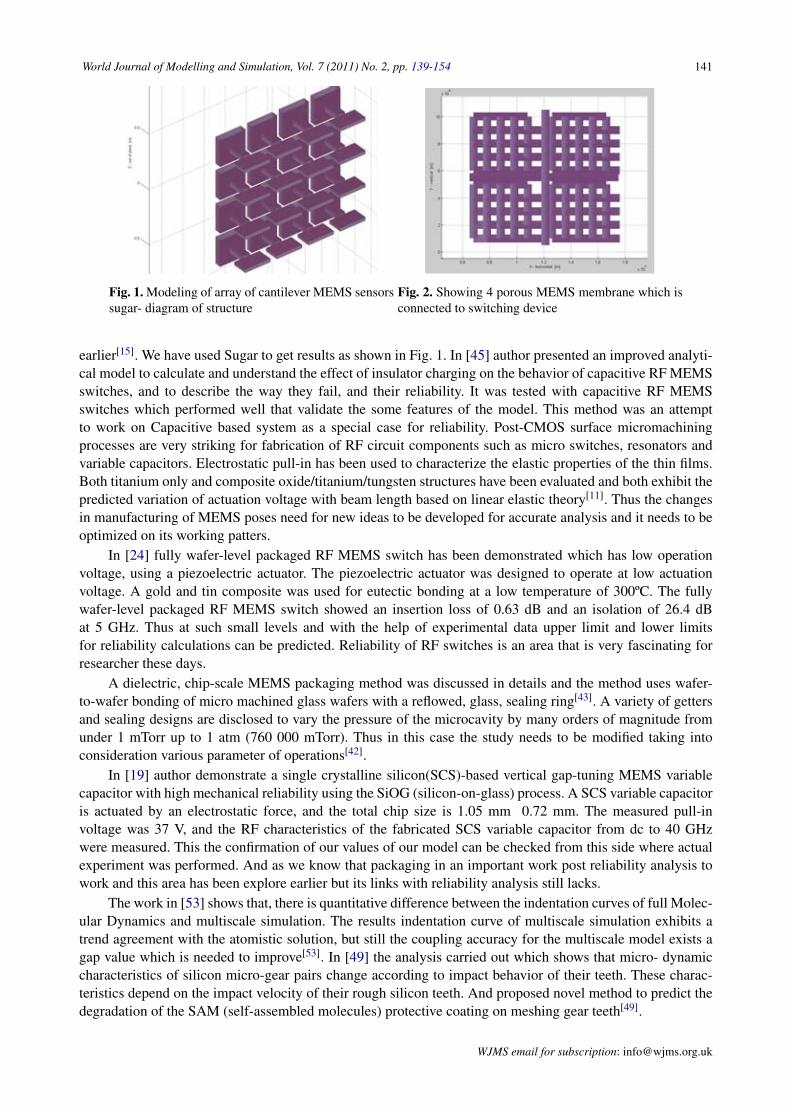
Fig. 1. Modeling of array of cantilever MEMS sensorssugar- diagram of structure
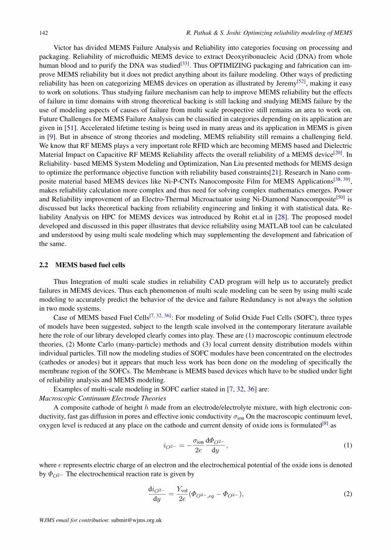
Fig. 2. Showing 4 porous MEMS membrane which isconnected to switching device
earlier[15]. We have used Sugar to get results as shown in Fig. 1. In [45] author presented an improved analyti-cal model to calculate and understand the effect of insulator charging on the behavior of capacitive RF MEMSswitches, and to describe the way they fail, and their reliability. It was tested with capacitive RF MEMSswitches which performed well that validate the some features of the model. This method was an attemptto work on Capacitive based system as a special case for reliability. Post-CMOS surface micromachiningprocesses are very striking for fabrication of RF circuit components such as micro switches, resonators andvariable capacitors. Electrostatic pull-in has been used to characterize the elastic properties of the thin films.Both titanium only and composite oxide/titanium/tungsten structures have been evaluated and both exhibit thepredicted variation of actuation voltage with beam length based on linear elastic theory[11]. Thus the changesin manufacturing of MEMS poses need for new ideas to be developed for accurate analysis and it needs to beoptimized on its working patters.
In [24] fully wafer-level packaged RF MEMS switch has been demonstrated which has low operationvoltage, using a piezoelectric actuator. The piezoelectric actuator was designed to operate at low actuationvoltage. A gold and tin composite was used for eutectic bonding at a low temperature of 300ºC. The fullywafer-level packaged RF MEMS switch showed an insertion loss of 0.63 dB and an isolation of 26.4 dBat 5 GHz. Thus at such small levels and with the help of experimental data upper limit and lower limitsfor reliability calculations can be predicted. Reliability of RF switches is an area that is very fascinating forresearcher these days.
A dielectric, chip-scale MEMS packaging method was discussed in details and the method uses wafer-to-wafer bonding of micro machined glass wafers with a reflowed, glass, sealing ring[43]. A variety of gettersand sealing designs are disclosed to vary the pressure of the microcavity by many orders of magnitude fromunder 1 mTorr up to 1 atm (760 000 mTorr). Thus in this case the study needs to be modified taking intoconsideration various parameter of operations[42].
In [19] author demonstrate a single crystalline silicon(SCS)-based vertical gap-tuning MEMS variablecapacitor with high mechanical reliability using the SiOG (silicon-on-glass) process. A SCS variable capacitoris actuated by an electrostatic force, and the total chip size is 1.05 mm 0.72 mm. The measured pull-involtage was 37 V, and the RF characteristics of the fabricated SCS variable capacitor from dc to 40 GHzwere measured. This the confirmation of our values of our model can be checked from this side where actualexperiment was performed. And as we know that packaging in an important work post reliability analysis towork and this area has been explore earlier but its links with reliability analysis still lacks.
The work in [53] shows that, there is quantitative difference between the indentation curves of full Molec-ular Dynamics and multiscale simulation. The results indentation curve of multiscale simulation exhibits atrend agreement with the atomistic solution, but still the coupling accuracy for the multiscale model exists agap value which is needed to improve[53]. In [49] the analysis carried out which shows that micro- dynamiccharacteristics of silicon micro-gear pairs change according to impact behavior of their teeth. These charac-teristics depend on the impact velocity of their rough silicon teeth. And proposed novel method to predict thedegradation of the SAM (self-assembled molecules) protective coating on meshing gear teeth[49].
WJMS email for subscription: [email protected]
142 R. Pathak & S. Joshi: Optimizing reliability modeling of MEMS
Victor has divided MEMS Failure Analysis and Reliability into categories focusing on processing andpackaging. Reliability of microfluidic MEMS device to extract Deoxyribonucleic Acid (DNA) from wholehuman blood and to purify the DNA was studied[33]. Thus OPTIMIZING packaging and fabrication can im-prove MEMS reliability but it does not predict anything about its failure modeling. Other ways of predictingreliability has been on categorizing MEMS devices on operation as illustrated by Jeremy[52], making it easyto work on solutions. Thus studying failure mechanism can help to improve MEMS reliability but the effectsof failure in time domains with strong theoretical backing is still lacking and studying MEMS failure by theuse of modeling aspects of causes of failure from multi scale prospective still remains an area to work on.Future Challenges for MEMS Failure Analysis can be classified in categories depending on its application aregiven in [51]. Accelerated lifetime testing is being used in many areas and its application in MEMS is givenin [9]. But in absence of strong theories and modeling, MEMS reliability still remains a challenging field.We know that RF MEMS plays a very important role RFID which are becoming MEMS based and DielectricMaterial Impact on Capacitive RF MEMS Reliability affects the overall reliability of a MEMS device[20]. InReliability- based MEMS System Modeling and Optimization, Nan Liu presented methods for MEMS designto optimize the performance objective function with reliability based constraints[21]. Research in Nano com-posite material based MEMS devices like Ni-P-CNTs Nanocomposite Film for MEMS Applications[38, 39],makes reliability calculation more complex and thus need for solving complex mathematics emerges. Powerand Reliability improvement of an Electro-Thermal Microactuator using Ni-Diamond Nanocomposite[50] isdiscussed but lacks theoretical backing from reliability engineering and linking it with statistical data. Re-liability Analysis on HPC for MEMS devices was introduced by Rohit et.al in [28]. The proposed modeldeveloped and discussed in this paper illustrates that device reliability using MATLAB tool can be calculatedand understood by using multi scale modeling which may supplementing the development and fabrication ofthe same.
2.2 MEMS based fuel cells
Thus Integration of multi scale studies in reliability CAD program will help us to accurately predictfailures in MEMS devices. Thus each phenomenon of multi scale modeling can be seen by using multi scalemodeling to accurately predict the behavior of the device and failure Redundancy is not always the solutionin two mode systems.
Case of MEMS based Fuel Cells[7, 32, 36]: For modeling of Solid Oxide Fuel Cells (SOFC), three typesof models have been suggested, subject to the length scale involved in the contemporary literature availablehere the role of our library developed clearly comes into play. These are (1) macroscopic continuum electrodetheories, (2) Monte Carlo (many-particle) methods and (3) local current density distribution models withinindividual particles. Till now the modeling studies of SOFC modules have been concentrated on the electrodes(cathodes or anodes) but it appears that much less work has been done on the modeling of specifically themembrane region of the SOFCs. The Membrane is MEMS based devices which have to be studied under lightof reliability analysis and MEMS modeling.
Examples of multi-scale modeling in SOFC earlier stated in [7, 32, 36] are:Macroscopic Continuum Electrode Theories
A composite cathode of height h made from an electrode/electrolyte mixture, with high electronic con-ductivity, fast gas diffusion in pores and effective ionic conductivity σion On the macroscopic continuum level,oxygen level is reduced at any place on the cathode and current density of oxide ions is formulated[8] as
iO2− = −σion
2e
dΦO2−
dy, (1)
where e represents electric charge of an electron and the electrochemical potential of the oxide ions is denotedby ΦO2− The electrochemical reaction rate is given by
diO2−
dy=
Yvol
2e(ΦO2−,eq − ΦO2−), (2)
WJMS email for contribution: [email protected]
World Journal of Modelling and Simulation, Vol. 7 (2011) No. 2, pp. 139-154 143
where Yvol is a rate constant for the volumetric reaction and ΦO2−,eq denotes the electrochemical potential ofO2− at zero current density.Monte Carlo (Many-Particle) Methods
In the Monte Carlo models the electrode is treated as a random mixture of particles of threephases:electrode, electrolyte, and gas. The electrochemical and electrical properties are analyzed using mul-tifarious types of resistors each for a different characteristic that needs to be measured. The current betweentwo solid particles of phase k is controlled by a resistor rk. It is related to the phase conductivity σk and ageometric factor fgeo mathematically as
rk =fgeo
σk, (3)
where fgeo justifies the particle shape and the contact necks between the adjacent particles.Local Current Density Distribution Models
The studies that have been performed on the modeling of local current density distributions on the in-dividual particle length scale have been implemented by finite element method, finite difference method orresistor network simulations carried out with many resistors in a single particle[7, 23]. This has been alsoshown in [32, 36].
The above model shows the requirements of reliability calculations for a MEMS based device. Herewe have to define the following for fuel cell, where intermittent failure is Membrane blockage, extendedfailure includes Partial damage to membrane and anodes which can be partial of complete, which may lead tocomplete failure or degraded failure in case of MEMS based fuel cell as shown in Fig. 2 and Fig. 3. Thus inthe system we can see how various systems needs to be considered and develop it in the failure distributionsystem. After studying the system and the failure classification we need to study the failure causes by whichcan calculate the complete system reliability. Need for switching device, has been shown in the figure below.
at any place on the cathode and current density of oxide ions is formulated [25] as
2
2 2ion O
O
di
e dyσ −
−
Φ= − (1)
where e represents electric charge of an electron and the electrochemical potential of the oxide ions is denoted by 2O −Φ . The electrochemical reaction rate is given by
( )2
2 2,2O vol
O eq O
di Ydy e
−
− −= Φ −Φ (2)
where volY is a rate constant for the volumetric reaction and
2 ,O eq−Φ denotes the electrochemical potential of 2O − at zero
current density. 2. Monte Carlo (Many-Particle) Methods
In the Monte Carlo models the electrode is treated as a random mixture of particles of three phases- (a) electrode, (2) electrolyte, and (3) gas . The electrochemical and electrical properties are analyzed using multifarious types of resistors each for a different characteristic that needs to be measured. The current between two solid particles of phase k is controlled by a resistor kr . It is related to the phase conductivity kσ and a
geometric factor geof mathematically as
/k geo kr f σ= (3)
where geof justifies the particle shape and the contact necks
between the adjacent particles. 3. Local Current Density Distribution Models The studies that have been performed on the modeling of
local current density distributions on the individual particle length scale have been implemented by finite element method, finite difference method or resistor network simulations carried out with many resistors in a single particle [24, 18]. This has been also shown in [17, 16].
The above model shows the requirements of reliability calculations for a MEMS based device. Here we have to define the following for fuel cell, where intermittent failure is Membrane blockage, extended failure includes Partial damage to membrane and anodes which can be partial of complete, which may lead to complete failure or degraded failure in case of MEMS based fuel cell as shown in fig. 2 and fig 3. Thus in the system we can see how various systems needs to be considered and develop it in the failure distribution system. After studying the system and the failure classification we need to study the failure causes by which can calculate the complete system reliability.
Need for switching device, has been shown in the figure below.
Fig.2 Showing 4 porous MEMS membrane which is connected to Switching
device
Fig. 3. Failure Classification of a MEMS device.
C. HDD modeling as per reliability constrains As given in [41] the electrostatic force in a parallel-plate actuator is given by (5) and it is derived from (4)
(4) and
Outputs V
Intermittent Failure
Extended Failure
Complete Failure
Partial Failure
Sudden Failure
Gradual Failure
Catastrophic Failure
Sudden Failure
Gradual Failure
Degraded Failure
1 2 01 2
1 1( ) ( )
C C C nhlg x g x
ε⎧ ⎫
= + = +⎨ ⎬− +⎩ ⎭
2
( )2
V CF xx
∂= − ⋅
∂
Fig. 3. Failure classification of a MEMS device
beam3d { junc[1], junc[2] ; material=p1, l=beamLength, w=2u }
f3d { junc[2] ; F=20u, oz=90 } beam3d { junc[2], junc[3] ; material=p1, l=prbl, w=2u,
oz=90 } end
III. MULTI-SCALE MODELING FOR MEMS
During the last two decades, the field of MEMS envisaged the progressive path starting from production of simple-function devices to more complex systems that includes many areas which changed wireless communications. They are useful in wide domains and are based on the same manufacturing technology. Although these tools have been successful in simulating the behavior of simple-function devices but fails when it goes to more complex areas because the physics developed cannot explain accurately all the properties, also they have not been as successful in simulating the behavior of more complex systems on a personal computer (PC) nor within a practical amount of time. Software proves its utility in technological advancements in MEMS by facilitating the design process and reducing the time of computation. Some of the features are packaged in a CAE for MEMS tool called SUGAR [12].
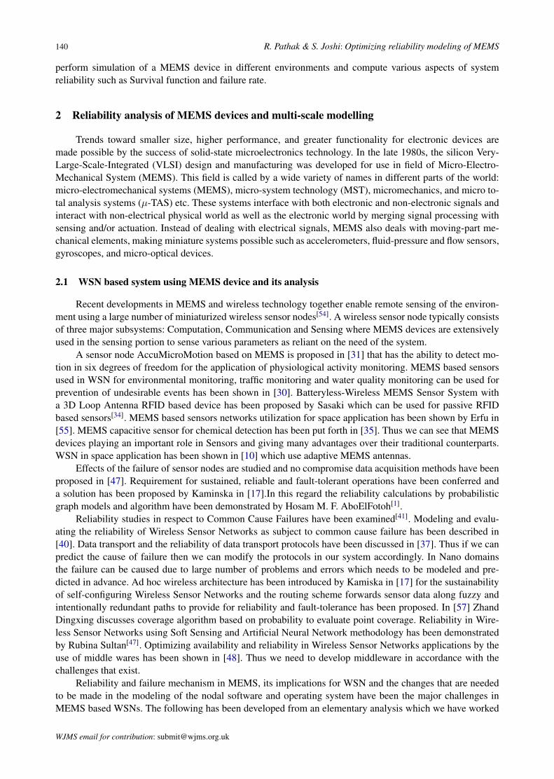
Fig. 6. Failure cause classification of MEMS based Device.
Although these tools have been successful in simulating the behavior of simple-function devices but fails when it goes to more complex areas because the physics developed cannot explain accurately all the properties, also they have not been as successful in simulating the behavior of more complex systems on a personal computer (PC) nor within a practical amount of time. Software proves its utility in technological advancements in MEMS by facilitating the design process and reducing the
time of computation. Some of the features are packaged in a CAE for MEMS tool called SUGAR [12].
With the ultimate goal of quickly and accurately simulating complex systems, we present efficient methods to configure, model, and simulate MEMS that are composed of a large number of lumped components, using HPC. Thus we can calculate various parameters required in reliability calculations from SUGAR as shown above. Now we need to build up a model and mathematical ground to integrate multi scale modeling with reliability.
TABLE I TABLE ABSTRACTION LAYERS IN MULTI-SCALE SETUP
Abstraction Scale Properties Nano CMOS 30-100nm Capacitance in CMOS RF MEMS 100-500nm Properties of antenna CNT 10-30 nm Conductance
Mechanical modeling 100-500nm, Electrical Modeling, Macro level modeling has been shown which are the part of the library developed. Mechanical modeling 100-500nm, Electrical Modeling, Macro level modeling has been shown which are the part of the library developed. This is the part of the code to distribute the computation among various nodes and synchronize the results. Thus after using the multi scale model, we need to get the mathematical backgrounds that need to be calculated with the HPC setup for reliability.
This analysis will be used on molding failure distribution function which is done in part 4. Mechanical modeling as from RF-MEMS prospective is given in [24] where MA (Nm) is the reaction moment at the left end, and RA (N) is the vertical reaction at the left end. The equations are:-
( )22A
PaM l al
= − − (10)
( )23 ( ) 2A
PR l a l al
= − + (11)
Mechanical modeling is an important part of the analysis which can be useful for mechanical failure analysis. Electrical Modeling it is the physics of 30-100nm, direct-tunneling current is formulated in a Nano CMOS circuit as per [25] is given by
( )3/233 8 2
, , , exp 1 18 3 | |
ox b oxG ox ox b
b ox ox b
m V qqJ C V V th hq E
π φφ
π φ ε φ
⎧ ⎫⎡ ⎤⎛ ⎞⎪ ⎪⎢ ⎥= − − −⎨ ⎬⎜ ⎟⎢ ⎥⎝ ⎠⎪ ⎪⎣ ⎦⎩ ⎭ (12)
Equivalent Circuit parameters it’s a macro level’ is the study of things at abstraction scale. MEMS-Based Inductively Coupled RFID Transponder for Implantable Wireless Sensor Applications has been shown in [23]. And the formulae for induced voltage at the MEMS based transponder is, which of macro level given [23] below
Design Failure
Weakness Failure
Sudden Failure
Gradual Failure
Use
Failure Causes
Manufacturin
Design
Manufacturing Failure
Fig. 4. Failure cause classification of MEMS based de-vice
2.3 HDD modeling as per reliability constrains
As given in [12] the electrostatic force in a parallel-plate actuator is given by Eq. (5) and it is derivedfrom Eq. (4)
C = C1 + C2 = nhlε0
{1
(g1 − x)+
1(g2 + x)
}, (4)
WJMS email for subscription: [email protected]
144 R. Pathak & S. Joshi: Optimizing reliability modeling of MEMS
F (x) = −v2
2· ∂C
∂x=
nhlε0
2
{1
(g1 − x)2+
1(g2 + x)2
}V 2, (5)
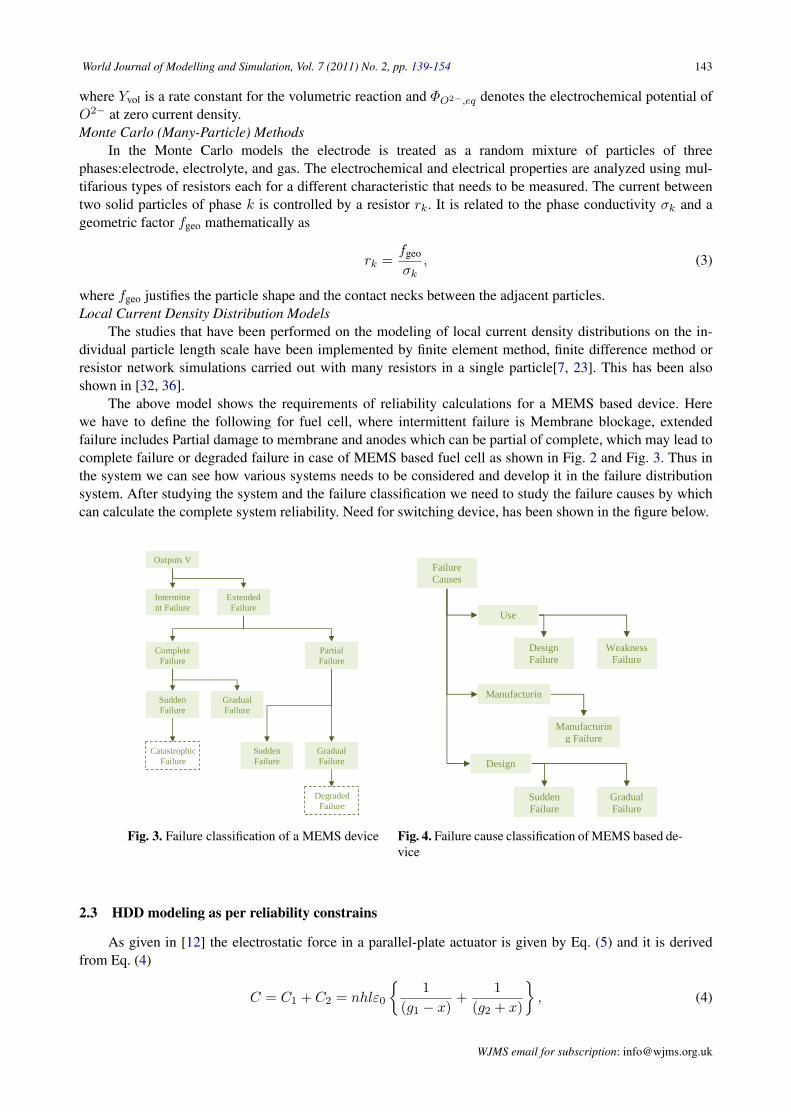
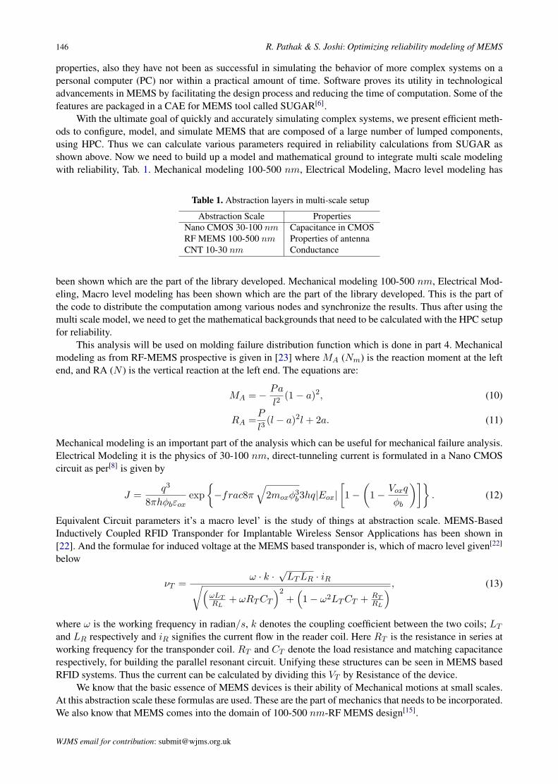
where C1 and C2 are the capacitances of gaps g1 and g2 respectively, x is the lateral distance along the strokefrom the resting point, and ε0 is the dielectric constant in a vacuum. Given below, Fig. 5 is the MATLABM-File code to generate a graph between Force and Distance of a parallel plate actuator, depicting Eq. (4).The generated graph is shown in Fig. 8. Thus we have proposed the interlinking of reliability and modelinganalysis in MATLAB which gives us liberty and power to do work on case specific reliability analysis whichis not included in any CAD today. As specified in [46] the folded springs have a spring force that is given by
System with a 3D Loop Antenna RFID based device has been proposed by Sasaki which can be used for passive RFID based sensors [49]. MEMS based sensors networks utilization for space application has been shown by Erfu in [48]. MEMS capacitive sensor for chemical detection has been put forth in [46]. Thus we can see that MEMS devices playing an important role in Sensors and giving many advantages over their traditional counterparts. WSN in space application has been shown in [47] which use adaptive MEMS antennas.
Effects of the failure of sensor nodes are studied and no compromise data acquisition methods have been proposed in [56]. Requirement for sustained, reliable and fault-tolerant operations have been conferred and a solution has been proposed by Kaminska in [50].In this regard the reliability calculations by probabilistic graph models and algorithm have been demonstrated by Hosam M. F. AboElFotoh [52].
Reliability studies in respect to Common Cause Failures have been examined [55]. Modeling and evaluating the reliability of Wireless Sensor Networks as subject to common cause failure has been described in [53]. Data transport and the reliability of data transport protocols have been discussed in [54]. Thus if we can predict the cause of failure then we can modify the protocols in our system accordingly. In Nano domains the failure can be caused due to large number of problems and errors which needs to be modeled and predicted in advance. Ad hoc wireless architecture has been introduced by Kamiska in [50] for the sustainability of self-configuring Wireless Sensor Networks and the routing scheme forwards sensor data along fuzzy and intentionally redundant paths to provide for reliability and fault-tolerance has been proposed. In [57] Zhand Dingxing discusses coverage algorithm based on probability to evaluate point coverage. Reliability in Wireless Sensor Networks using Soft Sensing and Artificial Neural Network methodology has been demonstrated by Rubina Sultan [56]. Optimizing availability and reliability in Wireless Sensor Networks applications by the use of middle wares has been shown in [51]. Thus we need to develop middleware in accordance with the challenges that exist.
Reliability and failure mechanism in MEMS, its implications for WSN and the changes that are needed to be made in the modeling of the nodal software and operating system have been the major challenges in MEMS based WSNs. The following has been developed from an elementary analysis which we have worked earlier [38]. We have used Sugar to get results as shown in Fig. 1.
CODE I ARRAY OF SENSORS
use("mumps.net") use("stdlib.net") gap=300u gridDim=gap/3 fringeDim=40u beamw = gridDim-fringeDim beaml=200u --Array junction junction = { node{} } for n=0,3 do --z for m=0,3 do --y --Nodes junction[n] = node{0, m*gap, n*gap} junction[n+1] = node{} junction[n+2] = node{} junction[n+3] = node{} junction[n+4] = node{0, (m*gap), (n*gap)-(gap-beamw)/2} --Beams beam3d { junction[n], junction[n+1] ; material=p1, l=gap-
beamw, w=gap-beamw, h=beamw, oy=90} anchor { junction[n] ; material=p1, l=gap-beamw, w=gap-
beamw, h=beamw, oy=90} beam3d { junction[n+4], junction[n+2] ; material=p1,
l=beaml, w=beamw, h=beamw, ox=90} beam3d { junction[n+2], junction[n+3] ; material=p1,
l=beaml/1.5, w=beamw/2, h=beamw*4, ox=90} end end
Fig. 1. Modeling of Array of cantilever MEMS sensors SUGAR- Diagram of Structure.
In [26] author presented an improved analytical model to calculate and understand the effect of insulator charging on the behavior of capacitive RF MEMS switches, and to describe the way they fail, and their reliability. It was tested with capacitive RF MEMS switches which performed well that validate the some features of the model. This method was an attempt to work on Capacitive based system as a special case for
Fig. 5. CODE I Array of sensors
Fig. 10. F(t), R(t), f(t) shown for an assumed exponential function.
V. HPC CODE FOR COMPUTATION
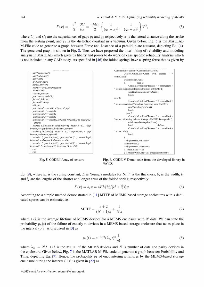
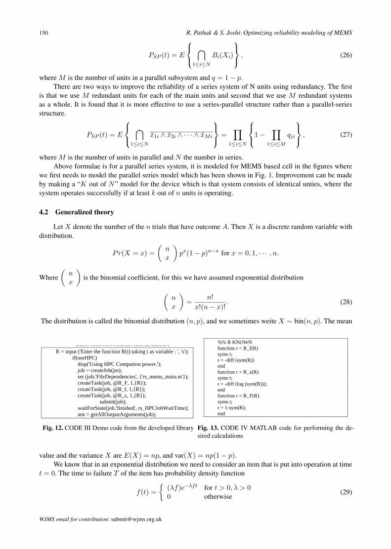
Parallel MATLAB has been used in Signal Processing as shown by Nadya T. to solve many problems [13]. Efficiently use Parallel MATLAB is the ket to its proper optimization something regarding which are shown by RON CHOY [14] helps us in optimizing MATLAB for HPC in reliability calculations. Thus we can see that MATLAB provided an excellent platform to work with Distributive computing and HPC. We have calculated the following using MATLAB HPC Distributed computing toolbox. This is the part of the code to distribute the computation among various nodes. It is being developed for Microsoft Compute Cluster Server Environment. We have included this in the paper because it’s the best alternative for multi scale computation and was used for verification of the results obtained on other setups. This is an alternative approach for computation which is being explored for such computations.
CODE V DEMO CODE FROM THE DEVELOPED LIBRARY IN WCCS
Communicator comm = Communicator.world; Console.WriteLine("Check from process " + comm.Rank); switch (comm.Rank) { case 0: Console.WriteLine("Process " + comm.Rank + " status: calculating Reaction Moment of MEMS"); calcReactionMomentFrmCase(); break; case 1: Console.WriteLine("Process " + comm.Rank + " status: calculating Tunneling Current of nano CMOS"); calcTunnelingFrmCase(); break; case 2: Console.WriteLine("Process " + comm.Rank + "status: calculating Induced Voltage of MEMS Transponder"); calcInducedVoltageFrmCase(); break; default: Console.WriteLine("Process " + comm.Rank + " status: Idle"); break; } /*All processes join here*/ comm.Barrier(); /*All processes completed*/ if (comm.Rank == 0) { Console.WriteLine ("All processes finished"); } Thus after using the multi scale model, we need to get the mathematical backgrounds that need to be calculated with the HPC setup for reliability. The out of the computation are shown in fig. 11.
Fig. 11. Results of the multi scale computations.
VI. SPEEDUP OPTIMIZED WITH MULTI-SCALE MODELING
As shown in the speed up diagram we can significantly speed up calculations using MATLAB distributive computing
Fig. 6. CODE V Demo code from the developed library inWCCS
Eq. (9), where ks is the spring constant, E is Young’s modulus for Ni, h is the thickness, bs is the width, l1and l2 are the lengths of the shorter and longer arms of the folded spring, respectively:
F (x) = ksx = 4Eh{b3s/(l31 + l32)}x. (6)
According to a simple method demonstrated in [11] MTTF of MEMS-based storage enclosures with s dedi-cated spares can be estimated as
MTTF =s + 2
(N + 1)λ+
1Nλ
, (7)
where 1/λ is the average lifetime of MEMS devices for a MEMS enclosure with N data. We can state theprobability pn(t) of the failure of exactly n devices in a MEMS-based storage enclosure that takes place inthe interval (0, t] as discussed in [3] as
pn(t) = e−λN t(λN t)n 1n!
, (8)
where λN = Nλ, 1/λ is the MTTF of the MEMS devices and N is number of data and parity devices inthe enclosure. Given below, Fig. 7 is the MATLAB M-File code to generate a graph between Probability andTime, depicting Eq. (7). Hence, the probability pk of encountering k failures by the MEMS-based storageenclosure during the interval (0, t] is given in [22] as
WJMS email for contribution: [email protected]
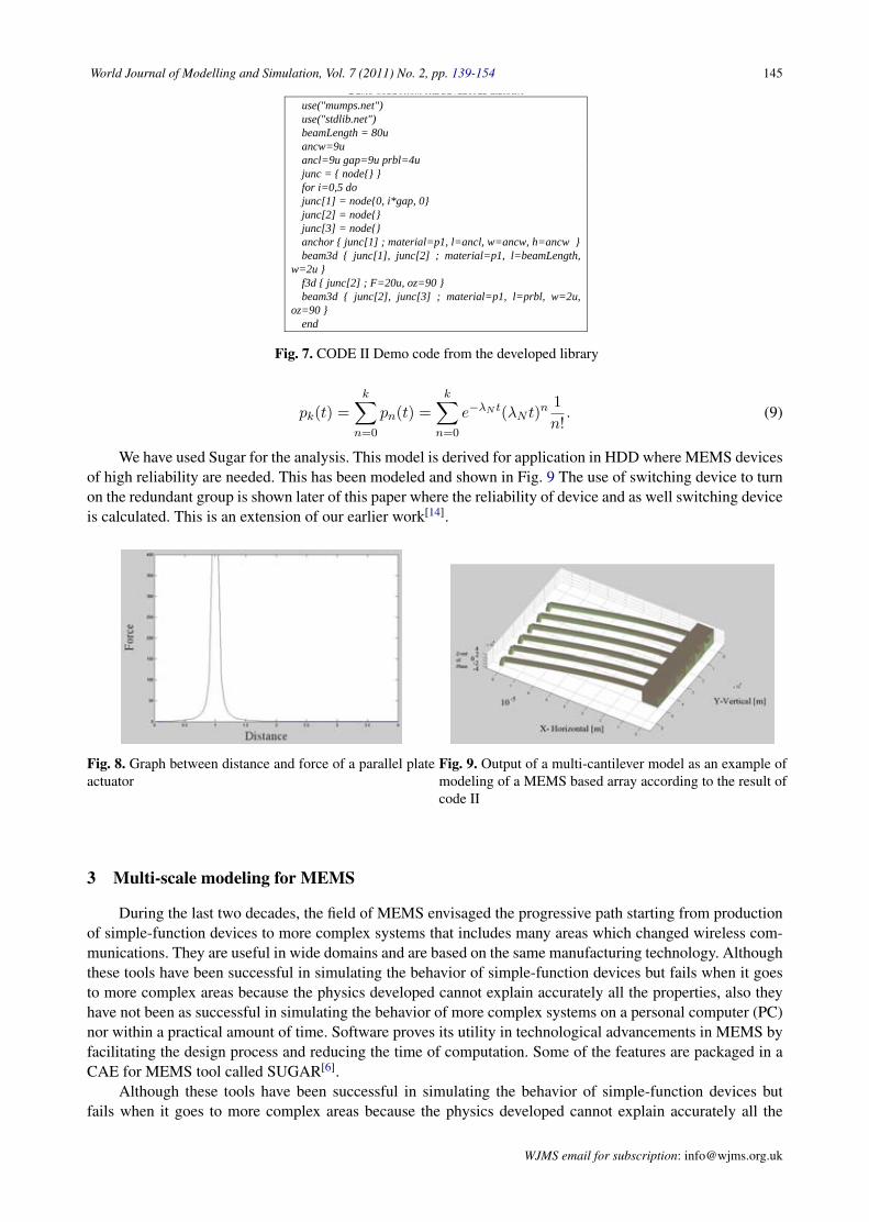
World Journal of Modelling and Simulation, Vol. 7 (2011) No. 2, pp. 139-154 145CODE II DEMO CODE FROM THE DEVELOPED LIBRARY
use("mumps.net") use("stdlib.net") beamLength = 80u ancw=9u ancl=9u gap=9u prbl=4u junc = { node{} } for i=0,5 do junc[1] = node{0, i*gap, 0} junc[2] = node{} junc[3] = node{} anchor { junc[1] ; material=p1, l=ancl, w=ancw, h=ancw } beam3d { junc[1], junc[2] ; material=p1, l=beamLength,
w=2u } f3d { junc[2] ; F=20u, oz=90 } beam3d { junc[2], junc[3] ; material=p1, l=prbl, w=2u,
oz=90 } end
III. MULTI-SCALE MODELING FOR MEMS
During the last two decades, the field of MEMS envisaged the progressive path starting from production of simple-function devices to more complex systems that includes many areas which changed wireless communications. They are useful in wide domains and are based on the same manufacturing technology. Although these tools have been successful in simulating the behavior of simple-function devices but fails when it goes to more complex areas because the physics developed cannot explain accurately all the properties, also they have not been as successful in simulating the behavior of more complex systems on a personal computer (PC) nor within a practical amount of time. Software proves its utility in technological advancements in MEMS by facilitating the design process and reducing the time of computation. Some of the features are packaged in a CAE for MEMS tool called SUGAR [12].
Fig. 6. Failure cause classification of MEMS based Device.
Although these tools have been successful in simulating the behavior of simple-function devices but fails when it goes to more complex areas because the physics developed cannot explain accurately all the properties, also they have not been as successful in simulating the behavior of more complex systems on a personal computer (PC) nor within a practical amount of time. Software proves its utility in technological advancements in MEMS by facilitating the design process and reducing the time of computation. Some of the features are packaged in a CAE for MEMS tool called SUGAR [12].
With the ultimate goal of quickly and accurately simulating complex systems, we present efficient methods to configure, model, and simulate MEMS that are composed of a large number of lumped components, using HPC. Thus we can calculate various parameters required in reliability calculations from SUGAR as shown above. Now we need to build up a model and mathematical ground to integrate multi scale modeling with reliability.
TABLE I TABLE ABSTRACTION LAYERS IN MULTI-SCALE SETUP
Abstraction Scale Properties Nano CMOS 30-100nm Capacitance in CMOS RF MEMS 100-500nm Properties of antenna CNT 10-30 nm Conductance
Mechanical modeling 100-500nm, Electrical Modeling, Macro level modeling has been shown which are the part of the library developed. Mechanical modeling 100-500nm, Electrical Modeling, Macro level modeling has been shown which are the part of the library developed. This is the part of the code to distribute the computation among various nodes and synchronize the results. Thus after using the multi scale model,
Design Failure
Weakness Failure
Sudden Failure
Gradual Failure
Use
Failure Causes
Manufacturin
Design
Manufacturing Failure
Fig. 7. CODE II Demo code from the developed library
pk(t) =k∑
n=0
pn(t) =k∑
n=0
e−λN t(λN t)n 1n!
. (9)
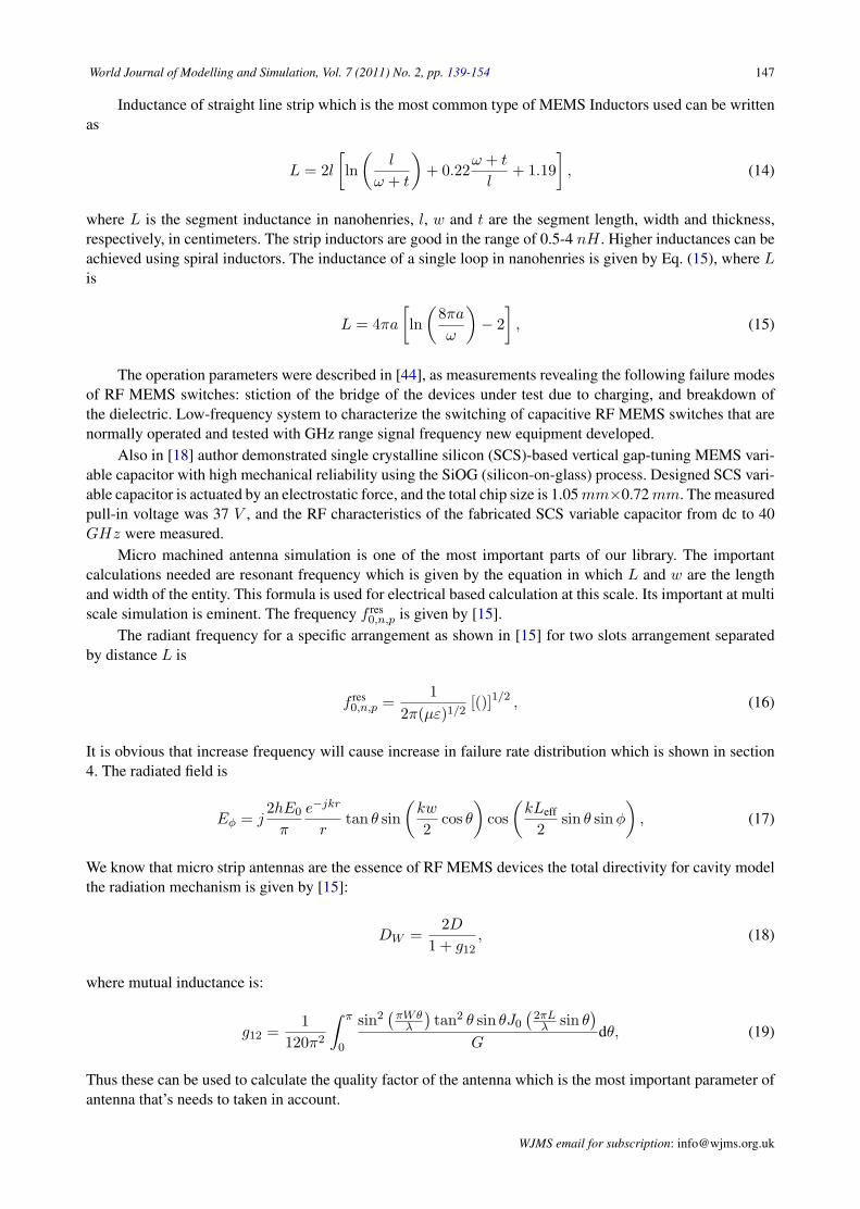
We have used Sugar for the analysis. This model is derived for application in HDD where MEMS devicesof high reliability are needed. This has been modeled and shown in Fig. 9 The use of switching device to turnon the redundant group is shown later of this paper where the reliability of device and as well switching deviceis calculated. This is an extension of our earlier work[14].
Fig. 8. Graph between distance and force of a parallel plateactuator
Fig. 9. Output of a multi-cantilever model as an example ofmodeling of a MEMS based array according to the result ofcode II
3 Multi-scale modeling for MEMS
During the last two decades, the field of MEMS envisaged the progressive path starting from productionof simple-function devices to more complex systems that includes many areas which changed wireless com-munications. They are useful in wide domains and are based on the same manufacturing technology. Althoughthese tools have been successful in simulating the behavior of simple-function devices but fails when it goesto more complex areas because the physics developed cannot explain accurately all the properties, also theyhave not been as successful in simulating the behavior of more complex systems on a personal computer (PC)nor within a practical amount of time. Software proves its utility in technological advancements in MEMS byfacilitating the design process and reducing the time of computation. Some of the features are packaged in aCAE for MEMS tool called SUGAR[6].
Although these tools have been successful in simulating the behavior of simple-function devices butfails when it goes to more complex areas because the physics developed cannot explain accurately all the
WJMS email for subscription: [email protected]
146 R. Pathak & S. Joshi: Optimizing reliability modeling of MEMS
properties, also they have not been as successful in simulating the behavior of more complex systems on apersonal computer (PC) nor within a practical amount of time. Software proves its utility in technologicaladvancements in MEMS by facilitating the design process and reducing the time of computation. Some of thefeatures are packaged in a CAE for MEMS tool called SUGAR[6].
With the ultimate goal of quickly and accurately simulating complex systems, we present efficient meth-ods to configure, model, and simulate MEMS that are composed of a large number of lumped components,using HPC. Thus we can calculate various parameters required in reliability calculations from SUGAR asshown above. Now we need to build up a model and mathematical ground to integrate multi scale modelingwith reliability, Tab. 1. Mechanical modeling 100-500 nm, Electrical Modeling, Macro level modeling has
Table 1. Abstraction layers in multi-scale setup
Abstraction Scale PropertiesNano CMOS 30-100 nm Capacitance in CMOSRF MEMS 100-500 nm Properties of antennaCNT 10-30 nm Conductance
been shown which are the part of the library developed. Mechanical modeling 100-500 nm, Electrical Mod-eling, Macro level modeling has been shown which are the part of the library developed. This is the part ofthe code to distribute the computation among various nodes and synchronize the results. Thus after using themulti scale model, we need to get the mathematical backgrounds that need to be calculated with the HPC setupfor reliability.
This analysis will be used on molding failure distribution function which is done in part 4. Mechanicalmodeling as from RF-MEMS prospective is given in [23] where MA (Nm) is the reaction moment at the leftend, and RA (N ) is the vertical reaction at the left end. The equations are:
MA =− Pa
l2(1− a)2, (10)
RA =P
l3(l − a)2l + 2a. (11)
Mechanical modeling is an important part of the analysis which can be useful for mechanical failure analysis.Electrical Modeling it is the physics of 30-100 nm, direct-tunneling current is formulated in a Nano CMOScircuit as per[8] is given by
J =q3
8πhφbεoxexp
{−frac8π
√2moxφ3
b3hq|Eox|[1−
(1− Voxq
φb
)]}. (12)
Equivalent Circuit parameters it’s a macro level’ is the study of things at abstraction scale. MEMS-BasedInductively Coupled RFID Transponder for Implantable Wireless Sensor Applications has been shown in[22]. And the formulae for induced voltage at the MEMS based transponder is, which of macro level given[22]
below
νT =ω · k ·
√LT LR · iR√(
ωLTRL
+ ωRT CT
)2+(1− ω2LT CT + RT
RL
) , (13)
where ω is the working frequency in radian/s, k denotes the coupling coefficient between the two coils; LT
and LR respectively and iR signifies the current flow in the reader coil. Here RT is the resistance in series atworking frequency for the transponder coil. RT and CT denote the load resistance and matching capacitancerespectively, for building the parallel resonant circuit. Unifying these structures can be seen in MEMS basedRFID systems. Thus the current can be calculated by dividing this VT by Resistance of the device.
We know that the basic essence of MEMS devices is their ability of Mechanical motions at small scales.At this abstraction scale these formulas are used. These are the part of mechanics that needs to be incorporated.We also know that MEMS comes into the domain of 100-500 nm-RF MEMS design[15].
WJMS email for contribution: [email protected]
World Journal of Modelling and Simulation, Vol. 7 (2011) No. 2, pp. 139-154 147
Inductance of straight line strip which is the most common type of MEMS Inductors used can be writtenas
L = 2l
[ln(
l
ω + t
)+ 0.22
ω + t
l+ 1.19
], (14)
where L is the segment inductance in nanohenries, l, w and t are the segment length, width and thickness,respectively, in centimeters. The strip inductors are good in the range of 0.5-4 nH . Higher inductances can beachieved using spiral inductors. The inductance of a single loop in nanohenries is given by Eq. (15), where Lis
L = 4πa
[ln(
8πa
ω
)− 2]
, (15)
The operation parameters were described in [44], as measurements revealing the following failure modesof RF MEMS switches: stiction of the bridge of the devices under test due to charging, and breakdown ofthe dielectric. Low-frequency system to characterize the switching of capacitive RF MEMS switches that arenormally operated and tested with GHz range signal frequency new equipment developed.
Also in [18] author demonstrated single crystalline silicon (SCS)-based vertical gap-tuning MEMS vari-able capacitor with high mechanical reliability using the SiOG (silicon-on-glass) process. Designed SCS vari-able capacitor is actuated by an electrostatic force, and the total chip size is 1.05 mm×0.72 mm. The measuredpull-in voltage was 37 V , and the RF characteristics of the fabricated SCS variable capacitor from dc to 40GHz were measured.
Micro machined antenna simulation is one of the most important parts of our library. The importantcalculations needed are resonant frequency which is given by the equation in which L and w are the lengthand width of the entity. This formula is used for electrical based calculation at this scale. Its important at multiscale simulation is eminent. The frequency f res
0,n,p is given by [15].The radiant frequency for a specific arrangement as shown in [15] for two slots arrangement separated
by distance L is
f res0,n,p =
12π(µε)1/2
[()]1/2 , (16)
It is obvious that increase frequency will cause increase in failure rate distribution which is shown in section4. The radiated field is
Eφ = j2hE0
π
e−jkr
rtan θ sin
(kw
2cos θ
)cos(
kLeff
2sin θ sinφ
), (17)
We know that micro strip antennas are the essence of RF MEMS devices the total directivity for cavity modelthe radiation mechanism is given by [15]:
DW =2D
1 + g12, (18)
where mutual inductance is:
g12 =1
120π2
∫ π
0
sin2(
πWθλ
)tan2 θ sin θJ0
(2πLλ sin θ
)G
dθ, (19)
Thus these can be used to calculate the quality factor of the antenna which is the most important parameter ofantenna that’s needs to taken in account.
WJMS email for subscription: [email protected]
148 R. Pathak & S. Joshi: Optimizing reliability modeling of MEMS
4 Developed reliability model and calculations
Multi scale analysis also is useful because it gives an idea about failure at different scales.We have assumed the analysis for MEMS devices to follow either of three distributions of reliability
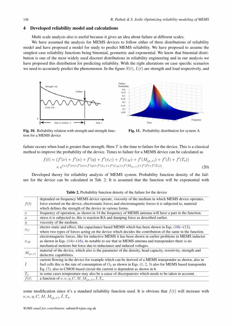
model and have proposed a model for study to predict MEMS reliability. We have proposed to assume thesimplest case reliability functions being binomial, geometric and exponential. We know that binomial distri-bution is one of the most widely used discreet distributions in reliability engineering and in our analysis wehave proposed this distribution for predicting reliability. With the right alterations on case specific scenarioswe need to accurately predict the phenomenon. In the figure S(t), L(t) are strength and load respectively, and
Fig. 7. Reliability relation with strength and strength function for a MEMS
device In the figure S(t), L(t) are strength and load respectively, and
failure occurs when load is greater than strength. Here T is the time to failure for the device. This is a classical method to improve the probability of the device.
Times to failure for a MEMS device can be calculated as
( , , )
( , , )
( ( ) ( ) ( ) ( ) ( ) ( ) ( ) ( ))
( ) ( ( ) ( ) ( ) ( ) ( ) ( ) ( ) ( ))
C M С r o
C M
С r o
t f f f f Є f Є f M f I f T
f t f f f f Є f Єf M f I f T
e ρ
ρ
υ κ η
υ κ η
′ ′ ′ ′ ′ ′ ′ ′− × + + + + + + +
′ ′ ′ ′ ′= + + + +′ ′ ′+ + + ×
(20) Developed theory for reliability analysis of MEMS system Probability function density of the failure for the device can
be calculated as follows:- f(t) is depended on frequency MEMS device operate,
viscosity of the medium in which MEMS device operates, force exerted on the device, electrostatic forces and electromagnetic forces it is subjected to, material which defines the strength of the device in various forms. υ= frequency of operation, as shown in 14 the frequency of MEMS antenna will have a part in the function κ = stress it is subjected to, this is reaction RA and damping
force as described earlier η = viscosity of the medium
ЄC = electro static and effect, like capacitance based MEMS which has been shown in equation 10, 11, 12 and 13, where two types of forces acting on the device which decides the contribution of the same in the function ЄM=electromagnetic forces, like for inductive MEMS it has been shown in earlier problems in MEMS inductor as shown in equation 14, 15 and 16, its notable to see that in MEMS antenna and transponders there is no mechanical motions but force due to inductance and induced voltages M (ρ, С, r) = material of the device, which also is the parameter of the density, head capacity, resistivity, strength and dielectric capabilities Ī=current flowing in the device for example which can be derived of a MEMS transponder as shown, also in fuel cells
this is the rate of consumption of O2 as shown in equation in equation 1, 2 and 3 also for MEMS based transponder equation 7, also in CMOS based circuit the current is dependent as shown in 6 To=in some cases temperature may also be a cause of discrepancies which needs to be taken in account
f(t) is a function of υ, κ, η, ЄC, ЄM, M (ρ, С, r), Ī, To We have discussed the physics of these devices which is It is assumed that the function will be exponential with some
modification since it’s a standard reliability function used. It is obvious that f(t) will increase with υ, κ, η, ЄC, ЄM,
M (ρ, С, r), Ī, To As these parameters are linked to the failure rate therefore to
insert their equivalent they are calculated by operator f’ where increase in any of them will increase the failure of the device, this operator converts the respective value to a function that needs to be inserted in the main failure probability distribution equation.
Also it is obvious that the variation will have an exponential distribution for the failure rate distribution which can be derived from the basic principle of exponential distribution of reliability theory
So, f(t) = (f(υ) + f(κ) + f(η) + f(ЄC) + f(ЄM ) + f(M (ρ, С, r)) + f(Ī) + f(To)) ×e– ( υ + κ + η + ЄC + ЄM + M (ρ, С, r) + Ī + To ))t (21)
( , , )( ( ) ( ) ( ) ( ) ( ) ( )C M С rf f f f Є f Є f M ρλ υ κ η′ ′ ′ ′ ′ ′= + + + + + (22) We have assumed we are given all parameters and they remain constant throughout the cycle of the MEMS device then (f(υ) + f(κ) + f(η) + f(ЄC) + f(ЄM ) + f(M (ρ, С, r)) + f(Ī) + f(To)) = λ is assumed constant for computation that is being done on MATLAB.
This formulation developed need to be modified as the exact dependencies of a case specific MEMS device for example MEMS based RFID or MEMS based fuel cell. For example ƛ need to derive for RFID which has MEMS based antenna and transponders.
This is a generic failure probability distribution, Thus the system can be taken to have probability
0, 0( )
0
te for tf t
otherwise
λλ λ−⎧ > >= ⎨⎩
(23)
This function is approximated by a continuous variable where we assume the Time to failure T is continuously distributed with probability density f(t) and distribution function is
HDD it depends in the frequency of operation, air drag, total number of times it has operated. WSN based sensors and system is depends the sensors and deformation, the air drag. Fuel cells it depends on the flow of material thorough the porous Membrane. Thus depending on the requirements we need to work on reliability formulations.
Fig. 10. Reliability relation with strength and strength func-tion for a MEMS device
Fig. 11. Probability distribution for system A
failure occurs when load is greater than strength. Here T is the time to failure for the device. This is a classicalmethod to improve the probability of the device. Times to failure for a MEMS device can be calculated as
f(t) = (f ′(ν) + f ′(κ) + f ′(η) + f ′(∈C) + f ′(∈M ) + f ′(M(ρ,,r)) + f ′(I) + f ′(To))
× et×(f ′(ν)+f ′(κ)+f ′(η)+f ′(∈C)+f ′(∈M )+f ′(M(ρ,,r))+f ′(I)+f ′(To)). (20)
Developed theory for reliability analysis of MEMS system. Probability function density of the fail-ure for the device can be calculated in Tab. 2: It is assumed that the function will be exponential with
Table 2. Probability function density of the failure for the device
f(t)depended on frequency MEMS device operate, viscosity of the medium in which MEMS device operates,force exerted on the device, electrostatic forces and electromagnetic forces it is subjected to, materialwhich defines the strength of the device in various forms.
ν frequency of operation, as shown in 14 the frequency of MEMS antenna will have a part in the function.κ stress it is subjected to, this is reaction RA and damping force as described earlier.η viscosity of the medium.
∈Celectro static and effect, like capacitance based MEMS which has been shown in Eqs. (10)∼(13),where two types of forces acting on the device which decides the contribution of the same in the function.
∈M
electromagnetic forces, like for inductive MEMS it has been shown in earlier problems in MEMS inductoras shown in Eqs. (14)∼(16), its notable to see that in MEMS antenna and transponders there is nomechanical motions but force due to inductance and induced voltages.
M(ρ,,r)material of the device, which also is the parameter of the density, head capacity, resistivity, strength anddielectric capabilities.
Icurrent flowing in the device for example which can be derived of a MEMS transponder as shown, also infuel cells this is the rate of consumption of O2 as shown in Eqs. (1, 2, 3) also for MEMS based transponderEq. (7), also in CMOS based circuit the current is dependent as shown in 6.
To in some cases temperature may also be a cause of discrepancies which needs to be taken in account.f(t) a function of ν, κ, η, C,M,M(ρ,,r), I, To.
some modification since it’s a standard reliability function used. It is obvious that f(t) will increase withν, κ, η, C,M,M(ρ,,r), I, To.
WJMS email for contribution: [email protected]
World Journal of Modelling and Simulation, Vol. 7 (2011) No. 2, pp. 139-154 149
As these parameters are linked to the failure rate therefore to insert their equivalent they are calculatedby operator f ′ where increase in any of them will increase the failure of the device, this operator converts therespective value to a function that needs to be inserted in the main failure probability distribution equation.
Also it is obvious that the variation will have an exponential distribution for the failure rate distributionwhich can be derived from the basic principle of exponential distribution of reliability theory. So
f(t) =(f ′(ν) + f ′(κ) + f ′(η) + f ′(∈C) + f ′(∈M ) + f ′(M(ρ,,r)) + f ′(I) + f ′(To))
× e(ν+κ+η+∈C+∈M+M(ρ,,r)+I+To)t, (21)
λ =f ′(ν) + f ′(κ) + f ′(η) + f ′(∈C) + f ′(∈M ) + f ′(M(ρ,,r)). (22)
We have assumed we are given all parameters and they remain constant throughout the cycle of the MEMSdevice then f ′(ν)+f ′(κ)+f ′(η)+f ′(∈C)+f ′(∈M )+f ′(M(ρ,,r))+f ′(I)+f ′(To) = λ is assumed constantfor computation that is being done on MATLAB, Fig. 12.
This formulation developed need to be modified as the exact dependencies of a case specific MEMSdevice for example MEMS based RFID or MEMS based fuel cell. For example λ need to derive for RFIDwhich has MEMS based antenna and transponders.
This is a generic failure probability distribution, Thus the system can be taken to have probability. Thisfunction is approximated by a continuous variable where we assume the time to failure T is continuouslydistributed with probability density f(t) and distribution function is:
f(t) ={
λe−λt for t > 0, λ > 00 otherwise
(23)
HDD it depends in the frequency of operation, air drag, total number of times it has operated. WSN basedsensors and system is depends the sensors and deformation, the air drag. Fuel cells it depends on the flow ofmaterial thorough the porous Membrane. Thus depending on the requirements we need to work on reliabilityformulations.
We have defined three systems with variation that are possible for calculations of exponential failuredistribution in the system. System A is defined as
f(t) ={
(λf)e−λft for t > 0, λ > 00 otherwise
(24)
4.1 Use of switching device
Switching technology has been used very effectively and since at MEMS devices we have MEMSswitches to shift to the redundant part of the system we need to analyze the reliability of the system withswitch added.
Psyst(t) = PSD(t)Pm(t) where Pm(t) is the probability of failure free operation of redundant group,PSD(t) of switching device and Psyst(t) of the system as a whole.
A specific reliability function of switching device can be calculated. This structure depicts the changesthat need to be made in the MEMS structures for redundant operation with switching device. In fuel cells thisswitching technology can prove to be very useful.
E
⋂i≤i≤n
=∏
i≤i≤n
e{xi = 1} =∏
i≤i≤n
ρi. (25)
A series system’s reliability decreases (increases) if the reliability of any unit decreases (increases). A seriessystem’s reliability decreases (increases) if the number of units increases (decreases). A series system’s reli-ability is worse than the reliability of any of its units. Thus these structures can be considered as parallel andseries structures for reliability calculations. For a series parallel structure, we know that
WJMS email for subscription: [email protected]
150 R. Pathak & S. Joshi: Optimizing reliability modeling of MEMS
PSP (t) = E
⋂1≤i≤N
Bi(Xi)
, (26)
where M is the number of units in a parallel subsystem and q = 1− p.There are two ways to improve the reliability of a series system of N units using redundancy. The first
is that we use M redundant units for each of the main units and second that we use M redundant systemsas a whole. It is found that it is more effective to use a series-parallel structure rather than a parallel-seriesstructure.
PSP (t) = E
⋂1≤i≤N
x1i ∧ x2i ∧ · · · ∧ xMi
=∏
1≤i≤N
1−∏
1≤i≤M
qji
, (27)
where M is the number of units in parallel and N the number in series.Above formulae is for a parallel series system, it is modeled for MEMS based cell in the figures where
we first needs to model the parallel series model which has been shown in Fig. 1. Improvement can be madeby making a “K out of N” model for the device which is that system consists of identical unties, where thesystem operates successfully if at least k out of n units is operating.
4.2 Generalized theory
Let X denote the number of the n trials that have outcome A. Then X is a discrete random variable withdistribution.
Pr(X = x) =(
nx
)px(1− p)n−x for x = 0, 1, · · · , n.
Where(
nx
)is the binomial coefficient, for this we have assumed exponential distribution
(nx
)=
n!x!(n− x)!
. (28)
The distribution is called the binomial distribution (n, p), and we sometimes weite X ∼ bin(n, p). The mean
We have distributed the 6 functions on reliability to 6 workers and results show that we can achieve considerable speed-up. The reliability functions area as follows:
Distribution function F(t)
( ) 1 ( )F t R t= − (30)
Probability density function f(t)
( ) ( )df t R tdt
= (31)
Failure Rate function z(t)
( ) ln ( )dz t R tdt
= − (32)
Reliability Survival function R(t)
( ) ( )t
R t f u du∞
= ∫ (33)
Mean time to failure MTTF
0
( )MTTF R t dt∞
= ∫ (34)
Mean residual life MRL
1( ) ( )( ) t
MRL t R x dxR t
∞
= ∫ (35)
Our Investigation was confined to calculation for exponential distribution
( ) ( 0, 0)tR t e tλ λ−= > > (36)
though we have included many others in our library.
The reliability (survivor) function of the item is
( ) Pr( ) ( ) 0t
t
R t T t f u du e fortλ∞
−= > = = >∫ (37)
Here we have assumed 9
11( )t
z t e−
= (38)
have calculated the following using MATLAB HPC Distributed computing toolbox [15]. The out of the various reliability parameters are shown in fig. 9 and 10.
CODE III DEMO CODE FROM THE DEVELOPED LIBRARY
R = input ('Enter the function R(t) taking t as variable : ', 's'); if(useHPC) disp('Using HPC Compution power.'); job = createJob(jm); set (job,'FileDependencies', {'rs_mems_main.m'}); createTask(job, @R_F, 1,{R}); createTask(job, @R_f, 1,{R}); createTask(job, @R_z, 1,{R}); submit(job); waitForState(job,'finished', rs_HPCJobWaitTime); ans = getAllOutputArguments(job);
CODE IV MATLAB CODE FOR PERFORMING THE DESIRED CALCULATIONS
%% R KNOWN function r = R_f(R) syms t; r = -diff (sym(R)) end function r = R_z(R) syms t; r = -diff (log (sym(R))); end function r = R_F(R) syms t; r = 1-sym(R); end
Fig. 9. Description of node status and number of workers.
The status of the HPC setup can be seen from the fig.9 which depends the number of workers that are assigned the task for the computation in MATLABTM distributive computing toolbox.
Fig. 12. CODE III Demo code from the developed library
We have distributed the 6 functions on reliability to 6 workers and results show that we can achieve considerable speed-up. The reliability functions area as follows:
Distribution function F(t)
( ) 1 ( )F t R t= − (30)
Probability density function f(t)
( ) ( )df t R tdt
= (31)
Failure Rate function z(t)
( ) ln ( )dz t R tdt
= − (32)
Reliability Survival function R(t)
( ) ( )t
R t f u du∞
= ∫ (33)
Mean time to failure MTTF
0
( )MTTF R t dt∞
= ∫ (34)
Mean residual life MRL
1( ) ( )( ) t
MRL t R x dxR t
∞
= ∫ (35)
Our Investigation was confined to calculation for exponential distribution
( ) ( 0, 0)tR t e tλ λ−= > > (36)
though we have included many others in our library.
The reliability (survivor) function of the item is
( ) Pr( ) ( ) 0t
t
R t T t f u du e fortλ∞
−= > = = >∫ (37)
Here we have assumed 9
11( )t
z t e−
= (38)
have calculated the following using MATLAB HPC Distributed computing toolbox [15]. The out of the various reliability parameters are shown in fig. 9 and 10.
CODE III DEMO CODE FROM THE DEVELOPED LIBRARY
R = input ('Enter the function R(t) taking t as variable : ', 's'); if(useHPC) disp('Using HPC Compution power.'); job = createJob(jm); set (job,'FileDependencies', {'rs_mems_main.m'}); createTask(job, @R_F, 1,{R}); createTask(job, @R_f, 1,{R}); createTask(job, @R_z, 1,{R}); submit(job); waitForState(job,'finished', rs_HPCJobWaitTime); ans = getAllOutputArguments(job);
CODE IV MATLAB CODE FOR PERFORMING THE DESIRED CALCULATIONS
%% R KNOWN function r = R_f(R) syms t; r = -diff (sym(R)) end function r = R_z(R) syms t; r = -diff (log (sym(R))); end function r = R_F(R) syms t; r = 1-sym(R); end
Fig. 9. Description of node status and number of workers.
The status of the HPC setup can be seen from the fig.9 which depends the number of workers that are assigned the task for the computation in MATLABTM distributive computing toolbox.
Fig. 13. CODE IV MATLAB code for performing the de-sired calculations
value and the variance X are E(X) = np, and var(X) = np(1− p).We know that in an exponential distribution we need to consider an item that is put into operation at time
t = 0. The time to failure T of the item has probability density function
f(t) ={
(λf)e−λft for t > 0, λ > 00 otherwise
(29)
WJMS email for contribution: [email protected]
World Journal of Modelling and Simulation, Vol. 7 (2011) No. 2, pp. 139-154 151
Table 3. The reliability functions area
Distribution function F (t) F (t) = 1−R(t)
Probability density function f(t) f(t) = ddtR(t)
Failure Rate function z(t) z(t) = − ddt lnR(t)
Reliability Survival function R(t) R(t) =∫∞
tf(u)du
Mean time to failure MTTF MITF =∫∞0
R(t)dt
Mean residual life MRL MRL(t) = 1R(t)
∫∞t
R(x)dx
This distribution is called the exponential distribution with parameter λ, and we sometimes write T ∼ exp(λ).We have distributed the 6 functions on reliability to 6 workers and results show that we can achieve consid-erable speed-up. The reliability functions area as Tab. 3: Our Investigation was confined to calculation forexponential distribution
R(t) = e−λt(t > 0, λ > 0), (30)
though we have included many others in our library. The reliability (survivor) function of the item is
R(t) = Pr(T > t) =∫ ∞
tf(u)du = e−λt for t > 0. (31)
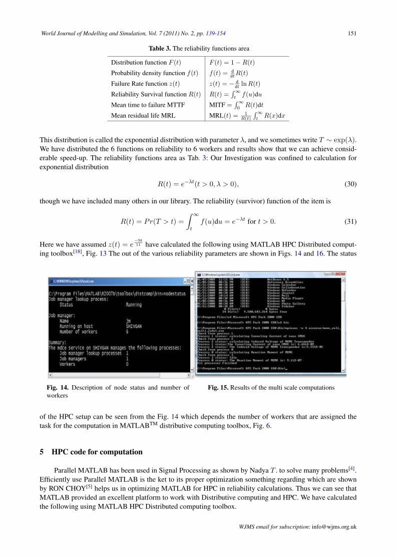
Here we have assumed z(t) = e−9t11 have calculated the following using MATLAB HPC Distributed comput-
ing toolbox[18], Fig. 13 The out of the various reliability parameters are shown in Figs. 14 and 16. The statusReliability Survival function R(t)
( ) ( )t
R t f u du∞
= ∫ (33)
Mean time to failure MTTF
0
( )MTTF R t dt∞
= ∫ (34)
Mean residual life MRL
1( ) ( )( ) t
MRL t R x dxR t
∞
= ∫ (35)
Our Investigation was confined to calculation for exponential distribution
( ) ( 0, 0)tR t e tλ λ−= > > (36)
though we have included many others in our library.
The reliability (survivor) function of the item is
( ) Pr( ) ( ) 0t
t
R t T t f u du e fortλ∞
−= > = = >∫ (37)
Here we have assumed 9
11( )t
z t e−
= (38)
have calculated the following using MATLAB HPC Distributed computing toolbox [15]. The out of the various reliability parameters are shown in fig. 9 and 10.
CODE III DEMO CODE FROM THE DEVELOPED LIBRARY
R = input ('Enter the function R(t) taking t as variable : ', 's');
if(useHPC) disp('Using HPC Compution power.'); job = createJob(jm); set (job,'FileDependencies', {'rs_mems_main.m'}); createTask(job, @R_F, 1,{R}); createTask(job, @R_f, 1,{R}); createTask(job, @R_z, 1,{R}); submit(job); waitForState(job, 'finished',
rs_HPCJobWaitTime); ans = getAllOutputArguments(job);
CODE IV MATLAB CODE FOR PERFORMING THE DESIRED CALCULATIONS
%% R KNOWN function r = R_f(R) syms t; r = -diff (sym(R)) end function r = R_z(R) syms t; r = -diff (log (sym(R)));
end function r = R_F(R) syms t; r = 1-sym(R); end
Fig. 9. Description of node status and number of workers.
The status of the HPC setup can be seen from the fig.9 which depends the number of workers that are assigned the task for the computation in MATLABTM distributive computing toolbox.
Fig. 10. F(t), R(t), f(t) shown for an assumed exponential function.
V. HPC CODE FOR COMPUTATION
Parallel MATLAB has been used in Signal Processing as shown by Nadya T. to solve many problems [13]. Efficiently use Parallel MATLAB is the ket to its proper optimization something regarding which are shown by RON CHOY [14] helps us in optimizing MATLAB for HPC in reliability calculations. Thus we can see that MATLAB provided an excellent platform to work with Distributive computing and HPC. We have calculated the following using MATLAB HPC Distributed computing toolbox. This is the part of the code to distribute the computation among various nodes. It is being developed for Microsoft Compute Cluster Server Environment. We have included this in the paper because it’s the best alternative for multi scale computation and was used for verification of the results
Fig. 14. Description of node status and number ofworkers
Fig. 15. Results of the multi scale computations
of the HPC setup can be seen from the Fig. 14 which depends the number of workers that are assigned thetask for the computation in MATLABTM distributive computing toolbox, Fig. 6.
5 HPC code for computation
Parallel MATLAB has been used in Signal Processing as shown by Nadya T . to solve many problems[4].Efficiently use Parallel MATLAB is the ket to its proper optimization something regarding which are shownby RON CHOY[5] helps us in optimizing MATLAB for HPC in reliability calculations. Thus we can see thatMATLAB provided an excellent platform to work with Distributive computing and HPC. We have calculatedthe following using MATLAB HPC Distributed computing toolbox.
WJMS email for subscription: [email protected]
152 R. Pathak & S. Joshi: Optimizing reliability modeling of MEMS
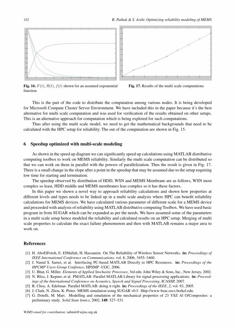
Fig. 16. F (t), R(t), f(t) shown for an assumed exponentialfunction
Fig. 17. Results of the multi scale computations
This is the part of the code to distribute the computation among various nodes. It is being developedfor Microsoft Compute Cluster Server Environment. We have included this in the paper because it’s the bestalternative for multi scale computation and was used for verification of the results obtained on other setups.This is an alternative approach for computation which is being explored for such computations.
Thus after using the multi scale model, we need to get the mathematical backgrounds that need to becalculated with the HPC setup for reliability. The out of the computation are shown in Fig. 15.
6 Speedup optimized with multi-scale modeling
As shown in the speed up diagram we can significantly speed up calculations using MATLAB distributivecomputing toolbox to work on MEMS reliability. Similarly the multi scale computation can be distributed sothat we can work on them in parallel with the powers of parallelization. Thus the result is given in Fig. 17.There is a small change in the slope after a point in the speedup that may be assumed due to the setup requiringlow time for starting and termination.
The speedup observed by distribution of HDD, WSN and MEMS Membrane are as follows, WSN mostcomplex so least, HDD middle and MEMS membranes leas complex so it has these factors.
In this paper we shown a novel way to approach reliability calculations and shown how properties atdifferent levels and types needs to be linked up in a multi scale analysis where HPC can benefit reliabilitycalculations for MEMS devices. We have calculated various parameter of different scale for a MEMS deviceand proceeded with analysis of reliability using MATLAB distributive computing Toolbox. We have used basicprogram in from SUGAR which can be expanded as per the needs. We have assumed some of the parametersin a multi scale setup hence modeled the reliability and calculated results on an HPC setup. Merging of multiscale properties to calculate the exact failure phenomenon and then with MATLAB remains a major area towork on.
References
[1] H. AboElFotoh, E. ElMallah, H. Hassanein. On The Reliability of Wireless Sensor Networks. in: Proceedings ofIEEE International Conference on Communications, vol. 8, 2006, 3455–3460.
[2] J. Namd S. Samsi, et al. Interfacing PC-based MATLAB Directly to HPC Resources. in: Proceedings of theHPCMP Users Group Confrence, HPSMP -UGC, 2006.
[3] U. Bhat, G. Miller. Elements of Applied Stochastic Processes, 3rd edn. John Wiley & Sons, Inc., New Jersey, 2002.[4] N. Bliss, J. Kepner, et al. PMATLAB: Parallel MATLAB Library for signal processing applications. in: Proceed-
ings of the International Conference on Acoustics, Speech and Signal Processing, ICASSP, 2007.[5] R. Choy, A. Edelman. Parallel MATLAB: doing it right. in: Proceedings of the IEEE, 2, vol. 93, 2005.[6] J. Clark, N. Zhou, K. Pister. MEMS simulation using SUGAR v0.5. Http://www-bsac.eecs.berkel.edu.[7] G. Dotelli, M. Mari. Modelling and simulation of the mechanical properties of 23 YSZ Al O/Composites: a
preliminary study. Solid State Ionics, 2002, 148: 527–531.
WJMS email for contribution: [email protected]
World Journal of Modelling and Simulation, Vol. 7 (2011) No. 2, pp. 139-154 153
[8] J. Fleig. Solid oxide fuel cell cathodes: Polarization mechanisms and modeling of the electrochemical performance.Annual Review of Materials Research, 2003, 33: 361–382.
[9] C. Fung. Issues of MEMS reliability and accelerated life time testing. in: Proceedings of the 43rd Annual Interna-tional Physics Symposium on Reliability, San Jose, 2005.
[10] E. Gaura, R. Newman. Wireless sensor networks: the quest for planetary field sensing. in: Proceedings of 31stIEEE Conference on Local Computer Networks, 2006, 596–603.
[11] M. Hill, C. Mahony, et al. Performance and reliability of post-CMOS metal/oxide MEMS for RF application. IOPJournal of Micromechanics and Microengineering, 2003, S131–S138.
[12] T. Imamura, M. Katayama, et al. MEMS-based integrated head/actuator/slider for hard disk drives. IEEE/ASMETransactions on Mechatronics, 1998, 3(3): 166–174.
[13] S. Joshi, R. Pathak. Reliability modeling and optimization of MEMS elements in various devices using multi-scaleconcepts. in: Conference on Innovative Technologies in Intelligent Systems & Industrial Applications, 2009.
[14] S. Joshi, R. Pathak, S. Ahmed. MATLAB modeling of HDD in light of the advances in nanotechnology and MEMS-based innovations. in: Conference on Innovative Technologies in Intelligent Systems & Industrial Applications,2009.
[15] S. Joshi, R. Pathak, S. Ahmed. Wireless sensor network: simulink modeling and reliability of Nano-Nodes. in:2nd International Workshop on Electron Devices and Semiconductor Technology, Indian Institute of TechnologyBombay, Mumbai, India, 2009.
[16] S. Joshi, R. Pathak, D. Mishra. MPI & PVM based HPC setup for multi-scale modeling. in: Proceedings IEEEInternational Advance Computing Conference, 2009.
[17] B. Kaminska, P. Gburzynski. Sustainability of self-configuring wireless sensor Networks. in: Proceedings of 14thIEEE International Conference on Electronics, Circuits and Systems, December, 2007, 1348–1351.
[18] J. Kim, S. Lee, et al. A mechanically reliable digital-type single crystalline silicon (SCS) RF MEMS variablecapacitor. IOP Journal of Micromechanics and Microengineering, 2005, 1854–1863.
[19] J. Kim, S. Lee, et al. A mechanically reliable digital-type single crystalline silicon (SCS) RF MEMS variablecapacitor. IOP Journal of Micromechanics and Microengineering, 2005, 1854–1863.
[20] T. Lisec, C. Huth, B. Wagner. Dielectric material impact on capacitive RF MEMS Reliability. in: Proceedings ofthe 34th European Microwave Conference, Amsterdam, 2004.
[21] N. Liu, S. Manoochehri. Reliability based MEMS system modeling and optimization. in: Proceedings of the 44thAnnual International Physics Symposium on Reliability, San Jose, 2006.
[22] H. Lu, C. Goldsmith, et al. MEMS-based inductively coupled RFID transponder for implantable wireless sensorapplications. IEEE Transactions on Magnetics, 2007, 43(6): 2412 – 2414.
[23] C. Mari, G. Dotelli. A random resistor model to forecast the electrical properties of crystalline ionic conductorcomposites. Solid State Ionics, 2000, 136: 1315–1319.
[24] J. Park, H. Lee, et al. A fully wafer-level packaged rf mems switch with low actuation voltage using a piezoelectricactuator. IOP Journal of Micromechanics and Microengineering, 2006, 2281–2286.
[25] R. Pathak, S. Joshi. Modeling nano enabled elements of solar cells and fuel cells. in: Conference on InnovativeTechnologies in Intelligent Systems & Industrial Applications, 2009.
[26] R. Pathak, S. Joshi. Multi scale modeling and intricate study of MEMS based elements in RFID systems. in:Conference on Innovative Technologies in Intelligent Systems & Industrial Applications, 2009.
[27] R. Pathak, S. Joshi. Optimizing reliability analysis of MEMS devices on an HPC setup using multi-scale modeling.in: Internation Conference on Software Technology & Engineering ICSTE2009 Organized by the InternationalAssociation of Computer Science & Information Technology, 2009.
[28] R. Pathak, S. Joshi, D. Mishra. Distributive computing for reliability Analysis of MEMS Devices using MATLAB.in: Proceedings ACM International Conference on Computing, Communication and Control, 2009.
[29] R. Pathak, S. Joshi, D. Mishra. Optimizing HPC for computational nanotechnology in MCCS environment. in:Proceedings 6th International Conference on Electrical Engineering/Electronics, Computer, Telecommunications,and Information Technology, 2009.
[30] A. Pathan, C. Hong, H. Lee. Smartening the Environment using wireless sensor networks in a developing country.in: Proc. ICACT, 2006.
[31] A. Sadat, H. Qu, et al. Low-Power CMOS wireless MEMS motion sensor for physiological activity monitoring.Transaction of IEEE on Circuits and Systems-I: Regular Papers, 2005, 52(12).
[32] N. Sammes. Fuel cell technology: reaching towards commercialization. Springer-Verlag, Amsterdam, 2006, 137–139.
[33] V. Samper, A. Trigg. MEMS failure analysis and Reliability. in: Proceedings of IPFA, Singapore, 2003.[34] S. Sasaki, T. Seki, et al. Batteryless-Wireless MEMS sensor system with a 3D loop antenna. Transaction of
Sensors, 2007, 252–255.
WJMS email for subscription: [email protected]
154 R. Pathak & S. Joshi: Optimizing reliability modeling of MEMS
[35] V. Saxena, T. Plum, et al. Design and fabrication of a MEMS capacitive chemical sensor system. in: Proceedingsof IEEE Workshop on Microelectronics and Electron Devices, 2006.
[36] Y. Seo, Y. Cho. A miniature direct methanol fuel cell using platinum sputtered microcolumn electrodes with limitedamount of fuel. in: IEEE The Sixteenth Annual International Conference on Micro Electro Mechanical Systems,Kyoto, 2003, 375–378.
[37] F. Shaikh, A. Khelil, N. Suri. On Modeling the reliability of data transport in wireless sensor networks. in: Pro-ceedings of 15th EUROMICRO International Conference on Parallel, Distributed and Network-Based Processing,2007, 395–402.
[38] G. Shen, Y. Cheng, et al. Synthesis and characterization of Ni-P-CNT’s Nanocomposite film for MEMS applica-tions. IEEE Transaction on Nanotechnology, 2005, 4(5).
[39] G. Shen, L. Tsai, et al. Ni-P-CNTs nanocomposite film for MEMS applications. in: Proceedings of the 4th IEEEConference on Nanotechnology, 2004.
[40] A. Shrestha, L. Xing, H. Liu. Modeling and evaluating the reliability of wireless sensor networks. in: AnnualReliability and Maintainability Symposium, Dept. of Electr. & Comput. Eng., Univ. of Massachusetts Dartmouth,MA, 2007, 186–191.
[41] A. Shrestha, L. Xing, H. Liu. Reliability modeling and analysis of wireless sensor networks. in: Proceedings ofIEEE Long Island Systems, Applications and Technology Conference, 2007, 1–4.
[42] D. Sparks, J. Trevino, et al. An all-glass chip-scale MEMS package with variable cavity pressure. IOP Journal ofMicromechanics and Microengineering, 2006, 2488–2491.
[43] D. Sparks, J. Trevino, et al. An all-glass chip-scale mems package with variable cavity pressure. IOP Journal ofMicromechanics and Microengineering, 2006, 2488–2491.
[44] W. Spengen, R. Puers, et al. A low frequency electrical test set-up for the reliability assessment of capacitive RFMEMS switches. IOP Journal of Micromechanics and Microengineering, 2003, 604–612.
[45] W. Spengen, R. Puers, et al. A comprehensive model to predict the charging and reliability of capacitive RF MEMSswitch. IOP Journal of Micromechanics and Microengineering, 2004, 514–521.
[46] W. Spengen, R. Puers, et al. A comprehensive model to predict the charging and reliability of capacitive RF MEMSswitch. IOP Journal of Micromechanics and Microengineering, 2004, 514–521.
[47] R. Sultan, M. Shafiq, N. Khan. Reliability in wireless sensor networks using soft sensing. in: Proceedings of 7thComputer Information Systems and Industrial Management Applications Conference, 2008, 139–144.
[48] A. Taherkordi, M. Taleghan, M. Sharifi. Achieving availability and reliability in wireless sensor networks ap-plications. in: Proceedings of The First International Conference on Availability, Reliability and Security, 2006,7.
[49] M. Teodorescu, S. Theodossiades, H. Rahnejat. Impact dynamics of rough and surface protected MEMS gears.Elsevier Journal of Trainbology International, 2009, 42: 197–205. DOI: 10.1016/j.triboint.2008.05.019.
[50] L. Tsai, G. Shen, et al. Power and reliability improvement of an electro-thermal microactuator using Ni-Diamondnanocomposite. in: Proceedings of the Electronic Components and Technology Conference, 2004.
[51] J. Walraven. Future challenges for MEMS failure analysis. in: Proceedings of International Test Conference, 2003,33.4.
[52] J. Walraven. Failure mechanisms in MEMS. in: Proceedings of the International Test Conference, 2006, 33.1.[53] C. Wang, S. Jian, et al. Multiscale simulation of nanoindentation on Ni (100) thin film. Elsevier Journal of Applied
Surface Science, 2008, 255: 3240–3250. DOI : 10.1016/j.apsusc.2008.09.034.[54] B. Warneke, K. Pister. MEMS for distributed wireless sensor networks. in: Proceedings of 9th International
Conference on Electronics, vol. 1, 2002, 291–294.[55] E. Yang, N. Haridas, et al. Multiobjective optimal design of MEMS-based reconfigurable and evolvable sensor
networks for space applications. in: Proceedings of Second NASA/ESA Conference on Adaptive Hardware andSystems, 2007, 27–34.
[56] M. Yoshiyuki, T. Hiroshi. Nano-scale simulation by the use of supercomputer electronic structure calculation ofmaterials. NEC Technical Journal, 2007, 2(1).
[57] D. Zhang, M. Xu, et al. Probabilistic coverage configuration for wireless sensor networks. Proceedings of Inter-national Conference on Wireless Communications, Networking and Mobile Computing, 2006, 1–4.
WJMS email for contribution: [email protected]