Embed Size (px)
Citation preview
Optimizing MEG Recovery Systems on Long Subsea Tiebacks
Patrick Wan, Senior Flow Assurance Engineer05 June 2013
� Overview
� Flow Assurance and MEG Design
� MEG Management
� Summary
2
Session Outline
� Various flow assurance challenges associated with a
long deepwater subsea tie-back of a gas-condensate
field
• Hydrate management
� Most long subsea tiebacks (> 30km) in cold waters tend
to be un-insulated and require hydrate inhibition
� Continuous hydrate inhibition using MEG or LDHI
• LDHI injection for low water production systems
• MEG injection for high water production systems
3
Overview
� MEG can be recovered at the host facility (low losses)
and recycled
� Depending on the location of the host facility (onshore /
offshore), the slug catcher size and MEG storage
requirements become important design factors (weight
and space) for offshore facilities.
4
Overview
� Flow Assurance (relative to MEG Design)
• Lean MEG flow from topside to wellhead
• Rich MEG flow from wellhead to inlet separator / slug catcher
� Hydrocarbons Process Group (relative to MEG Design)
• Rich MEG from inlet separator / slug catcher to MEG Regenerator
• Lean MEG from MEG Regenerator to Lean MEG injection Pump
5
FA & MEG Design
� Important for FA and HC Process Group to work together
• Optimization of Lean/Rich MEG flows/composition
• Total solution for hydrate prevention and MEG system design
� For more information:
• OTC 24177 - Flow Assurance Impacts on Lean / Rich MEG Circuit Chemistry and MEG Regenerator / Reclaimer Design
6
FA & MEG Design
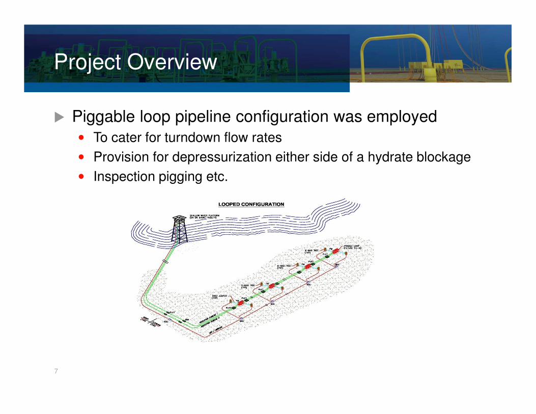
� Piggable loop pipeline configuration was employed
• To cater for turndown flow rates
• Provision for depressurization either side of a hydrate blockage
• Inspection pigging etc.
Project Overview
7
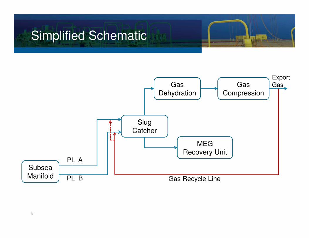
Simplified Schematic
Slug
Catcher
Gas
Dehydration
MEG
Recovery Unit
Subsea
Manifold
Gas
Compression
Export
Gas
8
PL A
PL B Gas Recycle Line
� Initially, depending on requirement, a single flowline can
be used for production and the other as a gas recycle
line
� Gas recycle facility in order to maintain high flow rates /
velocities in the single production line and hence limit
liquid holdup in the production line.
Gas Recycling
9
� Deep water gas field development, hydrates will form in
the presence of free water at low temperatures and high
pressures
� Hydrate blockages can result in long downtimes
� Rely on continuous hydrate inhibition (MEG) for hydrate
prevention
Hydrates
10
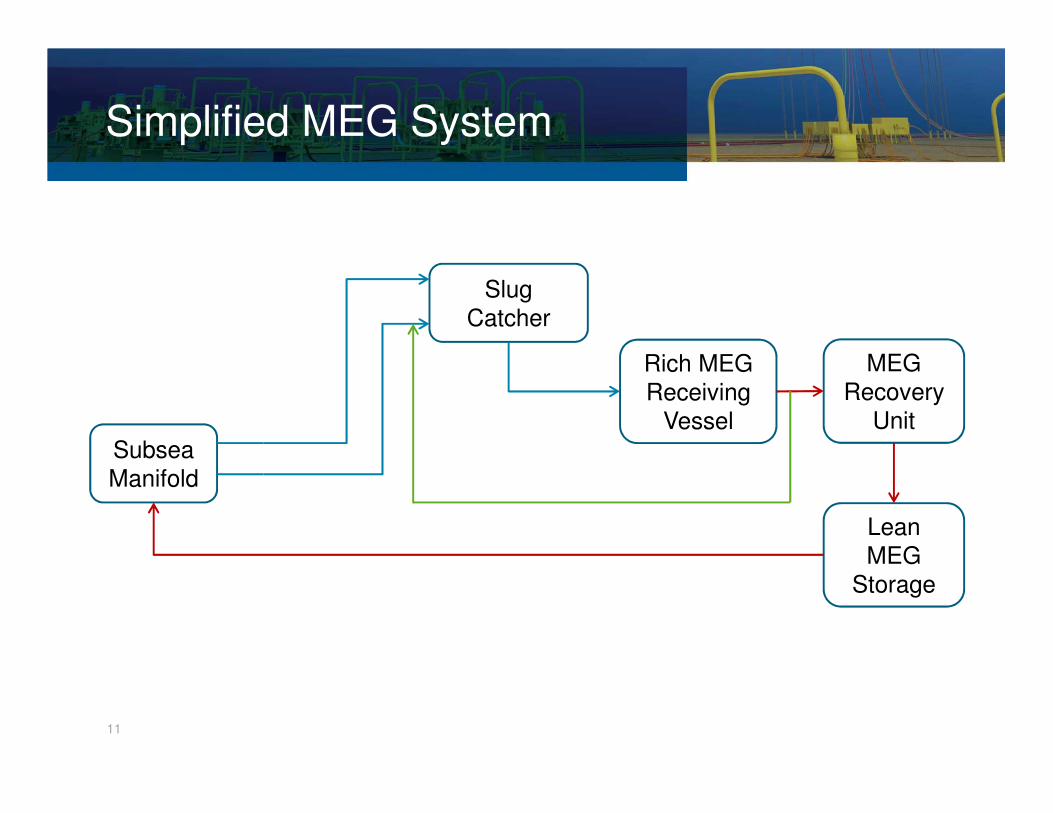
Simplified MEG System
Slug
Catcher
Rich MEG
Receiving
Vessel
Subsea
Manifold
MEG
Recovery
Unit
Lean
MEG
Storage
11
� MEG injection rates
• Increases with higher produced water rates
• Increases with higher SITHP
• Increases with higher degree of hydrate depression
� MEG design rates could be based on early / late life
production scenarios
12
MEG Management
� Slug catcher receives the well fluids• Gas – gas dehydration
• Condensate – condensate stabilization
• Water (with injected MEG) - sent to the Rich MEG vessel forrecovery
� During periods of low flow (turndown), flowline liquidholdups will increased
� There may be periods of Rich MEG starvation until newsteady state conditions are established (at turndown)
� The starvation period is important in terms of lean MEGstorage• Continuous lean MEG injection during starvation period
• No Rich MEG supply (starvation period) for recovery.
Issues
13
14
Arrival Rates Without Gas Recycle
15
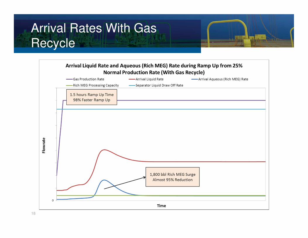
Arrival Rates With Gas Recycle
� By re-circulating gas during turndown conditions via one
flowline and producing through the other flowline the
liquid holdups do not increase significantly during
turndown.
� This reduces the effects of rich MEG starvation periods,
thus reducing lean MEG storage requirements during
turndown
16
17
Arrival Rates Without Gas Recycle
18
Arrival Rates With Gas Recycle
19
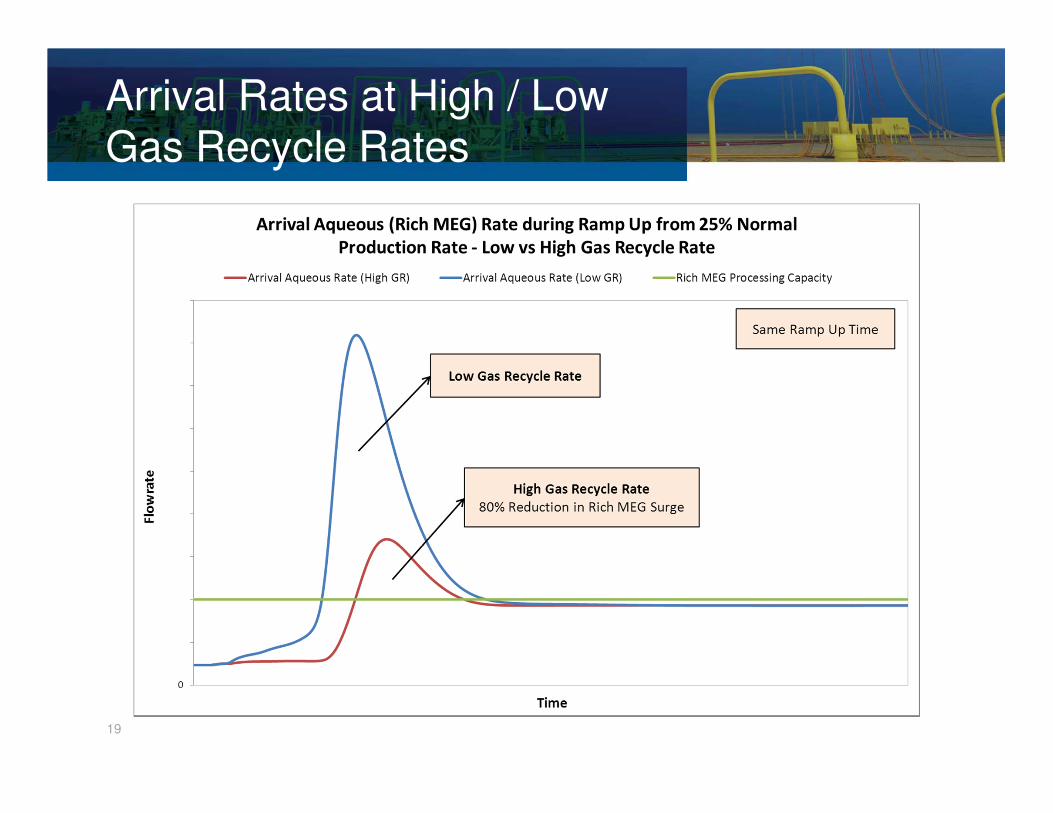
Arrival Rates at High / Low Gas Recycle Rates
� When flow is ramped up to normal design rates, ramp up
slugs are generated.
• May trip process on high liquid levels
� Water draw-off rate tends to be based on the
MEG + water processing capacity.
� To avoid large surge volume in the slug catcher or high
liquid processing capacity during flow ramp-up, ramp-up
period would need to be over a much longer time.
� Alternatively, a larger rich MEG receiving vessel or some
temporary storage can be considered for high liquid
draw-off rates for the water / MEG phase from the slug
catcher during ramp ups.
20
� There are a number of benefits of employing gas re-
circulation during low flow rate periods to limit liquid
holdups in flowlines for a looped configuration.
• Help optimize slug catcher size
• Help optimize MEG storage requirements
• Allow for faster ramp-up rates from turndown period
• Reduce / eliminate the severity of slugging during turndown /ramp up
Summary
21
Thank you
22