Embed Size (px)
Citation preview

© 2013 IEEE
Proceedings of the 28th Applied Power Electronics Conference and Exposition (APEC 2013), Long Beach, California, USA,March 17-21, 2013
Optimized Magnetic Design for Inductive Power Transfer Coils
R. Bosshard,J. Mühlethaler,J. W. Kolar,I. Stevanovic
This material is published in order to provide access to research results of the Power Electronic Systems Laboratory / D-ITET / ETH Zurich. Internal or personal use of this material is permitted. However, permission to reprint/republish this material for advertising or promotional purposes or for creating new collective works for resale or redistribution must be obtained from the copyright holder. By choosing to view this document, you agree to all provisions of the copyright laws protecting it.
Optimized Magnetic Design for InductivePower Transfer Coils
R. Bosshard∗, J. Muhlethaler∗, J. W. Kolar∗, and I. Stevanovic†∗Power Electronic Systems Laboratory, ETH Zurich, Switzerland, Email: [email protected]
†ABB Switzerland Ltd., Corporate Research, 5405 Baden-Dattwil, Switzerland
Abstract—Inductive Power Transfer (IPT) is well-established for ap-plications with biomedical implants and radio-frequency identificationsystems. Recently, also systems for the charging of the batteries ofconsumer electronic devices and of electric and hybrid electric vehicleshave been developed. The efficiency η of the power transfer of IPTsystems is given by the inductor quality factor Q and the magneticcoupling k of the transmission coils. In this paper, the influence of thetransmission frequency on the inductor quality factor and the efficiencyis analyzed taking also the admissible field emissions as limited bystandards into account. Aspects of an optimization of the magnetic designwith respect to a high magnetic coupling and a high quality factor arediscussed for IPT at any power level. It is shown that the magneticcoupling mainly depends on the area enclosed by the coils and that theirexact shape has only a minor influence. The results are verified with anexperimental prototype.
I. INTRODUCTION
Inductive Power Transfer (IPT) is well-established as a technique todeliver small amounts of energy to remote devices. It has been usedfor the supply of microelectronic implants such as neuromuscularstimulators, visual prostheses, and cortical implants [1]–[4] or even todeliver power to an artificial heart [5], [6]. In biomedical applications,IPT offers the possibility to reduce infections due to the eliminationof the previously required wired connections for the power and datatransmission that were running trough the patient’s skin.
Similarly, Radio-Frequency Identification (RFID) is a mature tech-nology that makes use of IPT to gather information from identifica-tion tags or remote sensors [7], [8]. Lately, also consumer electronicsapplications have emerged, for instance in the form of charging padsfor mobile phones [9], and IPT has been proposed for the chargingof the traction batteries of Electric and Hybrid Electric Vehicles(EV/HEV) in recent publications [10]–[15]. Domestic inductioncooking shall be mentioned as a related application [16]–[18], wheresimilar coil geometries and power electronic circuits are used atcomparable power levels.
Among the different IPT applications, similar performance criteriaexist for all power levels. For instance in biomedical applications,the amount of available space for an implant in the patients bodyis limited. Similar limitations also exist with EV/HEV applications.There, the space for the receiver coil on the underfloor of thevehicle is typically specified by the vehicle manufacturer. Hence,the size of the inductor coils and the power electronics is limited,which implies the requirement for a high power density of thetransmission coils. Additionally, the transmission efficiency shouldbe as high as possible to deliver the required output power with alow power loss and, in many applications, only a small resultingincrease of the operating temperature of the devices [13]. For anoptimal performance, the alignment of the transmission coils is ofhigh importance. In a practical system a misalignment of the coils islikely if no additional positioning aids are used. Therefore, an IPTsystem must also be capable of operating under these conditions.Another design constraint arises from the limitations on the leakageflux in the vicinity of the coils. In order to prevent health risks
resulting from induced electric fields in human tissue, specificallyin the brain and the retina, the emitted leakage fields are limited bystandards [19], [20].
The magnetic design of the transmission coils is of key importancein order to satisfy these requirements. Even though a large numberof magnetic structures for IPT inductors have been proposed inliterature, no systematic way for optimizing the magnetic design ofthe IPT coils was presented so far. Therefore, this paper aims toprovide a set of design guidelines for the magnetic optimization,namely the used operating frequency, the geometric design of thecoils and the use of core materials.
It was shown in [21], [22] that a Figure-of-Merit FOM = kQ givenby the product of the magnetic coupling k and the inductor qualityfactor Q limits the maximum efficiency of the power transmissionto approximately ηmax ≈ 1 − 2/(kQ). Hence, these two parametersshould be maximized in the design of the coils in order to achieve ahigh efficiency.
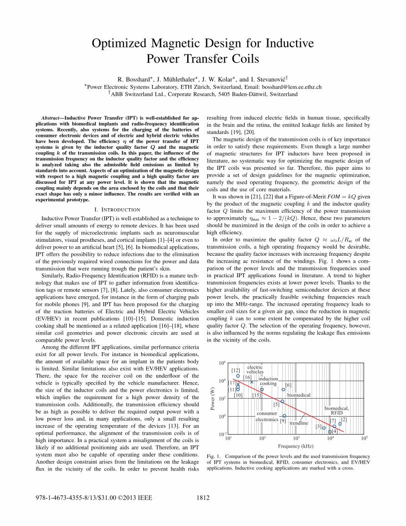
In order to maximize the quality factor Q ≈ ω0L/Rac of thetransmission coils, a high operating frequency would be desirable,because the quality factor increases with increasing frequency despitethe increasing ac resistance of the windings. Fig. 1 shows a com-parison of the power levels and the transmission frequencies usedin practical IPT applications found in literature. A trend to highertransmission frequencies exists at lower power levels. Thanks to thehigher availability of fast-switching semiconductor devices at thesepower levels, the practically feasible switching frequencies reachup into the MHz-range. The increased operating frequency leads tosmaller coil sizes for a given air gap, since the reduction in magneticcoupling k can to some extent be compensated by the higher coilquality factor Q. The selection of the operating frequency, however,is also influenced by the norms regulating the leakage flux emissionsin the vicinity of the coils.
101 102 103 104 10510-2
100
102
104
106
Frequency (kHz)
Pow
er (W
)
biomedical
biomedical,RFID
electricvehicles
inductioncooking
trendline
consumerelectronics [9]
[5]
[6]
[15]
[16][17][11]
[10]
[12]
[3][4]
[2][7]
Fig. 1. Comparison of the power levels and the used transmission frequencyof IPT systems in biomedical, RFID, consumer electronics, and EV/HEVapplications. Inductive cooking applications are marked with a cross.
978-1-4673-4355-8/13/$31.00 ©2013 IEEE 1812
How the switching frequency should be chosen taking all aspectsinto consideration is analyzed in more detail in Section II. A studyof the influence of the inductor geometry on the magnetic couplingk is presented in Section III. Later, in Section IV, the question ofan optimal selection and placement of the windings on the coil areais addressed. The size of the transmitter coil can still be adjusted,because in typical IPT applications only the size of the receiver coilis limited. The relative size of the receiver and transmitter coils arecommonly believed to be equal for an optimal coil design. However,this assumption can be disproved with a numerical calculation. Fromthe obtained results, suggestions for an optimal selection of thetransmitter coil size for a given receiver coil size and air gap widthare derived.
Especially at higher power levels, where the thermal constraintsbecome more restrictive, the use of magnetic materials for guidingthe magnetic flux is proposed to improve the coupling of the coils.Section V provides an insight into the advantages and disadvantagesof different core structures for IPT systems.
In order to support the obtained theoretical results, 2D and 3DFinite Element (FE) simulations are used throughout this paper. Ad-ditionally, a prototype inductor was constructed and an experimentalverification of the results is presented in Section VI.
II. SELECTION OF THE TRANSMISSION FREQUENCY
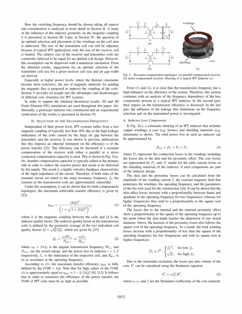
Independent of their power level, IPT systems suffer from a lowmagnetic coupling of typically less than 30% due to the high leakageinductance of the coils caused by the large air gap between thetransmitter and the receiver. It was shown in previous publicationsthat this imposes an inherent limitation on the efficiency η of thepower transfer [22]. The efficiency can be increased if a resonantcompensation of the receiver with either a parallel or a seriesconnected compensation capacitor is used. This is shown in Fig. 2(a)-(b). Another compensation capacitor is typically added at the primaryside in order to reduce the reactive power that needs to be deliveredby the supply. The result is a highly selective bandpass characteristicof the input impedance of the circuit. Therefore, if both sides of theresonant circuit are tuned to the same resonance frequency f0, thecurrents in the transmission coils are approximately sinusoidal.
Under this assumption, it can be shown that for both compensationtopologies, the maximum achievable transfer efficiency is given by[22]
ηmax =(kQ)2(
1 +√
1 + (kQ)2)2, (1)
where k is the magnetic coupling between the coils and Q is theinductor quality factor. The inductor quality factor of the transmissioncoils is defined by the geometric average of the two individual coilquality factors Q =
√Q1Q2, which are given by [23]
Qi =ω0WLi
Ploss,i≈ ω0LiRac,i
, (2)
where ω0 = 2πf0 is the angular transmission frequency, WLi andPloss,i are the stored energy and the power loss in inductor i = 1, 2respectively, Li is the inductance of the respective coil, and Rac,i isits ac resistance at the operating frequency.
According to (1), the maximum transfer efficiency ηmax is fullydefined by the FOM = kQ. Note that for high values of the FOM,(1) is approximately equal to ηmax ≈ 1−2/(kQ) [9], [13]. It followsthat in order to maximize the efficiency of the power transfer, theFOM of IPT coils must be as high as possible.
ÎL2C1
C2p
Î1
L1 L2
k
Û1 Û2
Î2
ÎL2C1 C2sÎ1
L1 L2
k
Û1 Û2
(a)
(b) (c)
windings
coreshielding
Fig. 2. Resonant compensation topologies: (a) parallel compensated receiver;(b) series compensated receiver. Drawing of a typical IPT inductor (c).
From (1) and (2), it is clear that the transmission frequency has ahigh influence on the efficiency of the system. Therefore, this sectioncontinues with an analysis of the frequency dependency of the losscomponents present in a typical IPT inductor. In the second part,their impact on the transmission efficiency is discussed. In the lastpart, the influence of the leakage flux limitations on the frequencyselection and on the transmitted power is investigated.
A. Inductor Loss Components
In Fig. 2(c), a schematic drawing of an IPT inductor that includescopper windings, a core (e.g. ferrite), and shielding materials (e.g.aluminum) is shown. The total power loss in such an inductor canbe approximated by
Ploss = Pw + Pc + Ps, (3)
where Pw represents the conduction losses in the windings includingthe losses due to the skin and the proximity effect. The core lossesare represented by Pc, and Ps stands for the eddy current losses inthe shielding materials of the inductor, if such components are partof the inductor design.
The skin and the proximity losses can be calculated from theamplitude of the winding current I , the external magnetic field thatpenetrates the windings, the operating frequency, and the parametersof the litz wire used for the construction [24]. It can be shown that theskin effect losses increase with a proportionality between linear andquadratic to the operating frequency for low frequencies, whereas forhigher frequencies they tend to a proportionality to the square rootof the operating frequency.
The losses due to the internal and the external proximity effectshow a proportionality to the square of the operating frequency up tothe point where the skin depth reaches the dimension of one stranddiameter. Above, the increase of the proximity losses also follows thesquare root of the operating frequency. As a result, the total windinglosses increase with a proportionality of less than the square of theoperating frequency for low frequencies and with its square root athigher frequencies
Pw ∝ I2 ·
{f<20 , for low f0√f0, for high f0.
(4)
Due to the sinusoidal excitation, the losses per unit volume of thecore P ′c can be calculated using the Steinmetz equation
P ′c = κfα0 Bβ , (5)
where κ, α, and β are the Steinmetz coefficients of the core material.
1813
100 101 102 103 104101
102
103
104
105
Frequency (kHz)
Q
self-resonance
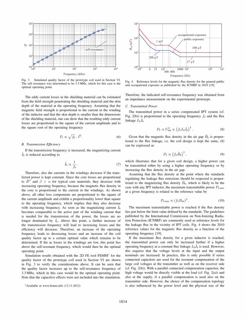
Fig. 3. Simulated quality factor of the prototype coil used in Section VI.The self resonance was determined to be 3.3 MHz, which for this case is theoptimal operating point.
The eddy current losses in the shielding material can be estimatedfrom the field strength penetrating the shielding material and the skindepth of the material at the operating frequency. Assuming that themagnetic field strength is proportional to the current in the windingof the inductor and that the skin depth is smaller than the dimensionsof the shielding material, one can show that the resulting eddy currentlosses are proportional to the square of the current amplitude and tothe square root of the operating frequency
Ps ∝√f0 · I2. (6)
B. Transmission Efficiency
If the transmission frequency is increased, the magnetizing currentIh is reduced according to
Ih ∝1
f0. (7)
Therefore, also the currents in the windings decrease if the trans-ferred power is kept constant. Since the core losses are proportionalto Bβ and β > α for typical core materials, they decrease withincreasing operating frequency, because the magnetic flux density inthe core is proportional to the current in the windings. As shownabove, all other loss components are proportional to the square ofthe current amplitude and exhibit a proportionality lower than squareto the operating frequency, which implies that they also decreasewith increasing frequency. As soon as the magnetizing current Ih
becomes comparable to the active part of the winding current thatis needed for the transmission of the power, the losses are nolonger dominated by Ih. Above this point, a further increase ofthe transmission frequency will lead to increasing losses and theefficiency will decrease. Therefore, an increase of the operatingfrequency leads to decreasing losses and an increase of the coilquality factor up to a certain optimal value which remains to bedetermined. If the ac losses in the windings are low, this point liesabove the self-resonant frequency, which would then be the optimaloperating point.
Simulation results obtained with the 2D FE tool FEMM1 for thequality factor of the prototype coil used in Section VI are shownin Fig. 3 to verify the considerations above. It can be seen thatthe quality factor increases up to the self-resonance frequency of3.3 MHz, which in this case would be the optimal operating point.Note that the capacitive effects were not included into the simulation.
1Available at www.femm.info (12.11.2012)
100 102 104 106 107100
102
104
106
Frequency (Hz)
B ref
(µT) public exposure
occupational exposure
200 µT
100 µT
1 mT
27 µT
25400300
8 3000
Fig. 4. Reference levels for the magnetic flux density for the general publicand occupational exposure as published by the ICNIRP in 2010 [19].
Therefore, the indicated self-resonance frequency was obtained froman impedance measurement on the experimental prototype.
C. Transmitted Power
The transmitted power in a series compensated IPT system (cf.Fig. 2(b)) is proportional to the operating frequency f0 and the fluxlinkage LhIh
Pδ ∝ U2ind ∝
(f0LhIh
)2. (8)
Given that the magnetic flux density in the air gap Bh is propor-tional to the flux linkage, i.e. the coil design is kept the same, (8)can be expressed as
Pδ ∝(f0Bh
)2, (9)
which illustrates that for a given coil design, a higher power canbe transmitted either by using a higher operating frequency or byincreasing the flux density in the air gap.
Assuming that the flux density at the point where the standardsregulating the leakage flux emissions should be respected is propor-tional to the magnetizing flux density Bh, which is likely to be thecase with any IPT inductor, the maximum transmittable power Pδ,max
at a given frequency is related to the reference value by
Pδ,max ∝ (f0Bref)2 . (10)
The maximum transmittable power is reached if the flux densitylies just below the limit value defined by the standards. The guidelinespublished by the International Commission on Non-Ionizing Radia-tion Protection (ICNIRP) are commonly used as reference levels forthe leakage flux in the vicinity of IPT coils. Fig. 4 shows the 2010reference values for the magnetic flux density as a function of theoperating frequency [19].
If the maximum flux density for a given inductor is reached,the transmitted power can only be increased further if a higheroperating frequency at a constant flux linkage LhIh is used. However,this requires that the voltage levels at the input and the outputterminals are increased. In practice, this is only possible if seriesconnected capacitors are used for the resonant compensation of thelarge coil voltages at the transmitter as well as on the receiver side(cf. Fig. 2(b)). With a parallel connected compensation capacitor, thehigh voltage would be directly visible at the load (cf. Fig. 2(a)) andalso at the supply, if a parallel compensation is used also on thetransmitter side. However, the choice of the compensation topologyis also influenced by the power level and the physical size of the
1814
system [13], [21]. To reach the maximum efficiency ηmax with a seriescompensation of the receiver coil, large inductors are required whichcould be undesirable. Therefore, an increase of the transmissionfrequency at a constant flux linkage LhIh may not be possible.
Additionally, note that a frequency increase only allows a higherpower transmission in the range from 25 to 300 Hz for the occupa-tional exposure reference level or to 400 Hz for the general publicexposure reference level, and between 3 kHz and 10 MHz, where therespective reference value is constant. In the range from 300 Hz or400 Hz to 3 kHz, however, the reference value is decreasing withBref ∝ 1/f0. In this region, a higher frequency requires a reductionof the magnetic flux density in the air gap. Therefore, the transmittedpower must remain constant
Pδ,max ∝(f0 ·
1
f0
)2
≡ 1 (11)
if the frequency is increased.
D. Discussion
In order to maximize the efficiency of an IPT system, the qualityfactor should be maximized. According to the considerations above,the operating frequency can be used for that purpose as was done forinstance in [25]. However, the quality factor only increases up to acertain maximum value. This frequency would then be the optimaloperating point from the point of view of the transmission efficiency.If this operating point lies above the self-resonance frequency of thecoils, i.e. if the ac losses in the windings are low, the self-resonantfrequency would be the optimal operating point. This was proposedfor instance in [26].
However, the losses in the power electronic circuits were not dis-cussed in these considerations. Even if soft-switching control methodsare used to reduce the switching losses at the higher frequencies [14],for instance the losses in conventional gate drivers will still increasefor a higher switching frequency. Additionally, if IGBTs are used forthe switches of the supply inverter, also high switching losses wouldoccur [27]. An optimum operating frequency could be determined ifthese factors were also included into the calculation. In conclusion,this shows that the power electronics are an important limiting partof an IPT system and must, therefore, be considered in an overallsystem optimization.
III. OUTER SHAPE OF THE INDUCTOR
Apart from the quality factor of the inductor, the magnetic couplingk defines the efficiency of the power transfer. For its maximization,an optimized magnetic design of the inductor is of high importance.
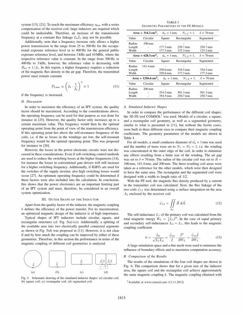
Typical shapes of IPT inductors include circular, square, andrectangular structures (cf. Fig. 5(a)-(c)). Additionally, a splitting ofthe available area into two electrically parallel connected segmentsas shown in Fig. 5(d) was proposed in [11]. However, it is not clearif and by how much the coupling can be improved by either of thesegeometries. Therefore, in this section the performance in terms of themagnetic coupling of different coil geometries is analyzed.
Î1Î1
Î1 Î1/2Î1/2
(a) (b) (c) (d)
Fig. 5. Schematic drawing of the simulated inductor shapes: (a) circular coil;(b) square coil; (c) rectangular coil; (d) segmented coil.
TABLE IGEOMETRY PARAMETERS OF THE FE MODELS
Area = 314.2 cm2, dw = 1 mm, N1,2 = 1, δ = 70 mm
Value Circular Square Rectangular Segmented
Radius 100 mm - - -Length - 177.3 mm 250.7 mm 250.7 mmWidth - 177.3 mm 125.3 mm 125.3 mm
Area = 628.3 cm2, dw = 1 mm, N1,2 = 1, δ = 70 mm
Value Circular Square Rectangular Segmented
Radius 141.4 mm - - -Length - 250.6 mm 354.5 mm 354.5 mmWidth - 250.6 mm 177.3 mm 177.3 mm
Area = 1256.6 cm2, dw = 1 mm, N1,2 = 1, δ = 70 mm
Value Circular Square Rectangular Segmented
Radius 200 mm - - -Length - 354.5 mm 501.3 mm 501.3 mmWidth - 354.5 mm 250.7 mm 250.7 mm
A. Simulated Inductor Shapes
In order to compare the performance of the different coil shapes,the 3D FE tool COMSOL2 was used. Models of a circular, a square,and a rectangular coil geometry, as well as a segmented geometry,similar to what is presented in [11], but without the ferrite cores,were built in three different sizes to compare their magnetic couplingcoefficients. The geometry parameters of the models are shown inTable I.
For all models, a small conductor diameter of dw = 1 mm was usedand the number of turns were set to N1 = N2 = 1, i.e. the windingwas concentrated at the outer edge of the coil, in order to minimizeany effects resulting from a finite size of the winding. The air gapwas set to δ = 70 mm. The radius of the circular coil was set to R =100 mm, 141.4 mm, and 200 mm. The three resulting coil areas weretaken as a reference for the other models, which were then designedto have the same area. The rectangular and the segmented coil weredesigned with a width to length ratio of 1/2.
With the FE tool, the magnetic flux density produced by a currentin the transmitter coil was calculated. Next, the flux linkage of thetwo coils ψ12 was determined using a surface integration on the areaA2 enclosed by the receiver coil
ψ12 =
∫A2
∫~B d ~A. (12)
The self-inductance L1 of the primary coil was calculated from thetotal magnetic energy WL = 1
2L1I
2. In the case of equal primaryand secondary self-inductances L2 = L1, this leads to the magneticcoupling coefficient
k =Lh√L1L2
=ψ12
I· I2
2WL=ψ12I
2WL. (13)
A large simulation space and a fine mesh were used to minimize theinfluence of boundary effects and to maximize computation accuracy.
B. Comparison of the Results
The results of the simulations of the four coil shapes are shown inFig. 6. The comparison shows that for a given size of the inductorarea, the square coil and the rectangular coil achieve approximatelythe same magnetic coupling k. The magnetic coupling obtained with
2Available at www.comsol.com (12.11.2012)
1815

0 0.05 0.1 0.15 0.2 0.25
1256.6
628.3
314.2
k
Are
a (c
m2 )
circularsquarerectangular
segmented
circularsquare
rectangularsegmented
circularsquare
rectangularsegmented
Fig. 6. Comparison of the results of the 3D FE simulations for the magneticcoupling k of the four inductor shapes shown in Fig. 5.
a circular coil of the same area is somewhat higher than that of thesquare and the rectangular coil. Presumably, this can be explainedby the distortion of the field distribution around the corners of thoseshapes. With good accuracy, it can be concluded from theses resultsthat the parameter that mainly influences the magnetic coupling isthe area enclosed by the inductor. The exact shape of the coil hasonly a minor influence.
Additionally, the results show that the segmented coil achievesa magnetic coupling that approximately corresponds to that of arectangular coil with only half the size. This can be explainedwith the example of two parallel connected transformers: if twoequal transformers are connected in parallel at their primary andsecondary terminals, the self-inductance of the combined device ishalf of that of a single transformer. The same holds for the mutualinductance. Therefore, the parallel connected transformers have thesame magnetic coupling than a single transformer. In the case ofthe segmented coil, each segment of the primary inductor togetherwith the corresponding segment of the secondary inductor can beconsidered a separate transformer, if the cross-coupling between thetwo transformers is considered to be small. Then it is clear that thecoupling of the complete inductor is approximately the same as thatof a single pair of segments, which in turn corresponds to that of arectangular coil with half the size.
In most IPT applications, the size of the receiver coil is limited.For biomedical systems, a small size of the implanted receiver isdesired to minimize the space that is required for its placement withinthe patient’s body. In applications with EV/HEV, a similar boundarycondition exists: the space that is available at the underfloor of avehicle is typically limited and relatively small when compared tothe air gap. Additionally, for this case often a rectangular area isspecified. According to the results presented in this section, the bestoption under these conditions is to fully utilize the available area forthe receiver and keep the provided area shape.
IV. UTILIZATION OF THE INDUCTOR AREA
It was shown in the previous section, that the exact shape of thecoils is less important than their size. Therefore, a set of circular spiralcoils is used for the analysis presented in this section. This allows touse an exact calculation instead of FE simulations, which simplifiesthe analysis significantly. The next step after the selection of aninductor shape is the design and the placement of the windings. In thefollowing, the influence of each of the remaining design parametersas shown in Fig. 7 on the magnetic coupling k of the coils is studied.
A. Calculation Method
For the calculation of the mutual inductance between two spiralcoils without core materials, semi-analytical equations3 exist [28].These equations can also be used for the calculation of the self-inductance, if they are adapted accordingly. Note that the equationsused in [28] are exact, if the numerical parts are evaluated withsufficient accuracy. A deviation of less than 5% from the inductancevalues obtained from FE simulations was observed.
In order to determine the influence of each of the design parametersoutlined in Fig. 7, a series of calculations was conducted wherethe parameters were varied one-by-one. For this process, the outerreceiver coil radius was assumed to be fixed to Ra,2 = 100 mm.All results are shown for the three different air gaps δ = 25, 75,and 150 mm. The number of turns of the receiver was set to N2 =15. The conductor diameter and the separation of the windings wereadjusted as described below.
B. Influence of the Conductor Diameter
In a first step, the diameter of the conductors in both coils wasvaried between 0.5 mm and 5 mm. The outer radius of the transmittercoil and the primary number of turns were constantly maintained atRa,1 = 100 mm and N1 = 15, equal to the parameters of the receiver.Also the inner radius was kept equal and constant at Ri = 11.5 mmfor both coils. This means that for a smaller conductor diameter, thewindings are separated more than for a large conductor diameter.
The result of the calculation of the magnetic coupling k at thethree different values of the air gap δ is shown in Fig. 8(a). Only alow variation of the coupling results from the variation of dw and sw.Apparently, the conductor diameter and the separation of the windingshave no significant influence on k.
C. Influence of the Number of Turns
A similar study can also be conducted for a variable number ofturns. The inner and outer radii of the coils were kept constant atthe same values as before. This time, the separation of the windingswas kept constant at sw = 1mm. The secondary number of turnswas also kept constant at N2 = 15. The primary number of turnsN1 was varied from 5 to 30 turns, while the conductor diameter wasadjusted such that the windings were equally distributed between theinner and the outer coil radius.
The calculated coupling coefficient is shown in Fig. 8(b). Becausethe secondary number of turns was not varied in this calculation,
3Due to the complexity of these equations, they are not repeated here forthe sake of clarity. However, their application is straight forward from thecited publication.
Ra
area coveredby winding
Ri
Symmetry swdw
N
Fig. 7. The design parameters of a circular spiral coils are the windingdiameter dw, the separation of the windings sw, the number of turns N , andthe inner and outer coil radius Ri, Ra respectively.
1816

1 2 3 4 50
0.2
0.4
0.6
dw (mm)
k
10 20 300
0.2
0.4
0.6
N1
k
10 30 50 70 900
0.2
0.4
0.6
Ri (mm)
k
100 200 300 400 5000
0.2
0.4
0.6
Ra,1 (mm)
k
(a) (b)
(c) (d)
15 255
δ = 25 mm
δ = 25 mm
δ = 75 mm
δ = 75 mm
δ = 150 mm
δ = 150 mm
δ = 25 mmδ = 75 mmδ = 150 mm
δ = 25 mm
δ = 75 mmδ = 150 mm
Fig. 8. Calculated coupling coefficient k for the air gaps δ = 25, 75, and150 mm: (a) variation of the conductor diameter in both coils; (b) variationof the primary number of turns; (c) variation of both inner coil radii; (d)variation of the outer radius of the transmitter coil.
the ratio N1/N2 was not constant. Except for the smallest air gapand for the lowest N1 values, where the separation of the windingsis largest, also the primary number of turns and the ratio N1/N2
have no significant impact on the coupling coefficient. This result isintuitively clear considering k = Lh/
√L1L2, where the number of
turns cancels out for conventional transformers.
D. Influence of the Inner Coil Radius
In the next step, the inner radii of the two coils were varied equallyfrom 10 mm to 90 mm (Ri,1 = Ri,2). The outer coil radii were againkept constant at 100 mm. This time, also the winding separation andthe conductor thickness were kept constant at sw = 1mm and dw =4.9mm respectively. The primary and the secondary number of turnswere adjusted to the variable inner radius.
The resulting coupling coefficients are shown in Fig. 8(c). Clearly,the inner coil radius has a significant influence on the magneticcoupling of the two coils. The magnetic coupling increases withdecreasing inner radius of the coils, which was also observed in [1].Accordingly, the inner radius of the spiral coil should be made assmall as possible to achieve a high magnetic coupling.
E. Influence of the Outer Coil Radius
In a last series of calculations, the magnetic coupling was deter-mined for a variable outer radius of the transmitter coil for a fixedsize of the receiver coil Ra,2 = 100mm. As a conclusion from theprevious step, the inner radii of both coils were set to zero, whichimplies N2 = 16 for these calculations. The conductor diameterand the winding separation were held constant at sw = 1mm anddw = 4.9mm, which means that the increased outer radius of thetransmitter coil was obtained by adding more primary windings.
The calculated magnetic coupling values are shown in Fig. 8(d).A maximum of the coupling coefficient can be observed at a certainouter radius of the transmitter coil, which is larger than that of thereceiver coil. Contrary to a common assumption, for larger air gapsthe maximum of the magnetic coupling k cannot be reached withcoils of equal size. Fig. 9 shows the contour lines of the magneticcoupling k for different air gaps and transmitter coil radii for a given
δ (mm)
R a,1 (m
m)
0.1
0.2
0.3
20 40 60 80 100 120 140 160 180 200100
150
200
250
300
350
400
450
500
0.05
0.05
0.05
0.1
0.15
0.250.350.4
optimal radius
Fig. 9. Contour lines of the magnetic coupling obtained for different valuesof the air gap δ and the transmitter coil radius Ra,1 for a given receiver coilwith Ra,2 = 100mm and N1 = N2 = 15 with dw = 4.9mm, sw = 1mm.
10-1 100 1010
1000
2000
3000
sw (mm)
Q
100 1010
1000
2000
3000
dw (mm)
Q
(a) (b)
sw = 0.7 mm dw = 4.9 mm
Fig. 10. Simulated quality factor at 100 kHz: (a) as a function of theconductor diameter dw at a constant separation sw = 0.7 mm of the windings;(b) as a function of the winding separation sw for a constant conductordiameter dw = 4.9 mm. The number of turns was adjusted to keep the innerand outer radii constant at Ri,1 = Ri,2 = 10 mm, Ra,1 = 105 mm, and Ra,2 =82 mm.
receiver coil radius of Ra,2 = 100mm and N1 = N2 = 15 withdw = 4.9mm, sw = 1mm. As indicated in the figure, the maximumof the magnetic coupling for a given air gap tends to larger valuesof Ra,1 > Ra,2. For larger air gaps, the effect is stronger.
It can be shown that for a fixed size of the receiver the mutualinductance Lh exhibits a maximum value at a certain transmitterradius, that is larger than the receiver radius. This explains why alsothe magnetic coupling shows a maximum at a larger transmitter thanreceiver coil radius.
F. Quality Factor
The above calculations show, that neither the conductor diameter,nor the winding separation, nor the number of turns have an influenceon the magnetic coupling. This allows the conclusion, that thedetermining factor for the magnetic coupling is the area covered bythe winding, as indicated in Fig. 7. Even though this analysis onlycovered a circular spiral coil, similar results are also expected forrectangular or square coil shapes.
However, the placement of the windings and the absolute length lwof the litz wire also influence the inductance and the resistance of thecoil, which define the inductor quality factor. Fig. 10(a) and (b) showsimulation results for the inductor quality factor Q as a function of theconductor diameter dw and the winding separation sw respectively.In the simulations, the number of turns was adjusted to keep theinner and the outer coil radius constant. Thus, the number of turnsincreases with N ∝ 1/dw if the conductor diameter is set to smaller
1817

Fig. 11. Photograph of one of the prototype IPT coils used in the experiments.
TABLE IIDATA OF THE EXPERIMENTAL PROTOTYPE
Variable Min. Value Max. Value
Outer radius 15.9 mm 105 mmInner radius 10 mm 99.1 mmNumber of turns 1 15
Variable Value
Litz wire 350 x 0.2 mmFerrite radius 105 mmFerrite thickness 3.75 mmRelative permeability 2000
values and it decreases if the winding separation is chosen larger. Itcan be seen in Fig. 10(a) that an increasing conductor diameter leadsto an improvement of the quality factor Q ≈ ω0L/R approximatelywith Q ∝ dw. If ac effects are neglected the winding resistance isreduced with R ∝ lw/d2w ∝ N3 and the inductance with L ∝ N2 ifa larger conductor diameter and a smaller number of turns is used.Hence, increasing the number of turns by using a thinner conductorleads to a reduction of the quality factor with Q ∝ 1/N .
Fig. 10(b) shows that a reduction of the winding separation sw
with an increasing number of turns leads to an increasing qualityfactor. This is because the conductor diameter dw is kept constant,therefore, the resistance R ∝ N is increased less than the inductance.Thus, increasing the number of turns by placing more windings ofthe same conductor on the coil area leads to a higher quality factor.This confirms that a spiral coil should have a small inner radius.
G. Discussion
Because the number of turns, the conductor diameter, and the sep-aration of the windings have no influence on the magnetic couplingk, these relations can be used to optimize the quality factor. Thebest option for a maximization of the FOM = kQ is to fully utilizethe available area by keeping its outer shape, and to fill the coilarea with closely spaced windings of a large diameter. However, notethat a small separation of the windings also increases the parasiticcapacitance and lowers the self-resonance frequency of the coils,which presents an upper limit for the operating frequency.
V. USE OF CORE MATERIALS
In order to improve the magnetic coupling of the inductor further,core materials can be used to guide the flux. They also help reducingthe leakage flux. If the available space for the coils is small, asfor instance those in biomedical applications, the addition of corematerial also offers the possibility to produce a higher inductance in
20 40 60 80 100 120 1400
0.2
0.4
0.6
0.8
δ (mm)
k
SimulatedMeasured
Fig. 12. Comparison between simulated and measured magnetic coupling kof the experimental prototype for different values of the air gap δ.
a given space. This can be required for the impedance matching withrespect to the load [22]. Among the potential core materials, ferriteis the most promising option due to its high relative permeabilityand the low losses at high frequencies, which is required to limitthe reduction of the quality factor that results from the core losses.The lower saturation flux density of this material can be tolerated,because the flux is distributed over a relatively large core volume.
For the designs investigated in this paper, mainly two core ar-rangements are possible: either a ferrite plane can be placed belowthe windings or a structure similar to a pot-core could be built.With a pot-core, the additional core material in the center of thecoil and around the outer radius of the windings would lead to thebest performance. A pot-core, however, leads to an increased inductorsize. Additionally, for a larger inductor, as would be required for anEV/HEV application, a pot-core has some disadvantages. A ferritestructure of a large size would be fragile and add significant weightto the coil. Moreover, it would need to be custom-made due to thelimited availability of large ferrite structures, which would increasethe manufacturing cost of inductor. Therefore, most solutions forlarger IPT coils found in literature use a ferrite plane built fromangular core segments or distributed I-cores as in [10]. This is alsotypically used in the related induction cooking applications [16]–[18].
VI. MEASUREMENT RESULTS
Based on the results of the presented analysis, an experimentalprototype system was constructed. Fig. 11 shows a photograph ofone of the designed IPT coils. The coils are constructed from a 350strand litz wire with a strand diameter of 0.2 mm. The outer diameterof the wire, including the insulation, is 5.2 mm and the windings areseparated by 0.7 mm. A coil former made from PVC was designedwith an outlet at every turn. In this way, the number of turns aswell as the inner and the outer coil diameters can be adjusted. Four90◦ ferrite core segments are placed in a compartment below thewindings. An aluminum shielding ring can be added at the outerradius of the coil to reduce the leakage flux. Table II contains thegeometry data of the prototype.
In order to verify the results of the FE analysis, the prototypetransmitter coil was wound with 15 turns. Therefore, its outer radiuswas Ra,1 = 105 mm and the inner radius was Ri,1 = 10 mm. Thereceiver had only 7 turns at an outer radius radius of Ra,2 = 82 mmand an inner radius of Ri,2 = 41 mm. The primary coil was fed with asinusoidal current with a peak value of 20 A and the induced voltagewas measured at the open terminals of the secondary while the airgap was increased from 32 mm to 132 mm. The measured couplingcoefficients together with the results of the FE simulation are shown
1818

in Fig. 12. The measured values and the simulation results are in goodagreement. The small deviation of the simulated values is presumablycaused by the (low) conductivity of the ferrite material, which wasassumed to be zero for the simulation. Note that for small air gaps,there is a slight increase of the self-inductances of the coils causedby the close proximity of the core of the opposite coil. Therefore, theself-inductances were re-measured for every air gap and the correctedvalues were included in the results shown in Fig. 12.
VII. CONCLUSION & FUTURE WORK
In this paper it was shown that the magnetic design is crucial fora high transmission efficiency of IPT systems of all power levels. Itwas shown that for a maximization of the inductor quality factor andthe transmission efficiency, the operating frequency can be increasedin order to reduce the magnetizing current. This leads to an efficiencyimprovement as long as the magnetizing current dominates the losses.At the frequency, where the active currents dominate the losses, anoptimal transmission frequency exists for a maximum transmissionefficiency. However, in a practical system the losses in the powerelectronics of the supply are likely to limit the operating frequencyto lower values. This trade-off will be analyzed in a future work.
It was shown that for a maximization of the magnetic coupling,the enclosed area of the coils is the most important parameter. Acomparison of circular, square, and rectangular inductor showed thatthe exact shape of the coil has only a minor influence. A more detailedcomparison of the robustness to misalignment and the leakage fluxemissions of these designs will be part of the future work.
It was shown for a circular spiral coil that the design parametersconductor diameter, winding separation, and the number of turns onlyhave a small influence on the magnetic coupling and that the areacovered by the winding is the most important factor. However, theinductor quality factor can be improved with an optimized placementof the windings. This can be used to optimize the FOM = kQ, forinstance if the operating frequency is limited to low values.
An experimental prototype was build to verify the results ofthe used FE simulations. A measurement of the magnetic couplingshowed that the simulations used in this paper are accurate withinless than a few percent.
ACKNOWLEDGMENT
The authors would like to thank ABB Switzerland Ltd. for theirfunding and for their support regarding many aspects of this researchproject. Additionally, the authors would like to thank E. Waffen-schmidt for the fruitful discussions that lead to this publication.
REFERENCES
[1] C. M. Zierhofer and E. S. Hochmair, “Geometric approach for couplingenhancement of magnetically coupled coils,” IEEE Trans. on BiomedicalEngineering, vol. 43, no. 7, pp. 708–714, 1996.
[2] M. Ghovanloo and S. Atluri, “A wide-band power-efficient inductivewireless link for implantable microelectronic devices using multiplecarriers,” IEEE Trans. on Circuits and Systems, vol. 54, no. 10, pp.2211–2221, 2007.
[3] R. R. Harrison, “Designing efficient inductive power links for im-plantable devices,” in Proc. of the IEEE International Symposium onCircuits and Systems (ISCAS), 2007, pp. 2080–2083.
[4] K. M. Silay, C. Dehollain, and M. Declercq, “Inductive power link fora wireless cortical implant with biocompatible packaging,” in Proc. ofthe IEEE Sensors Conference, 2010, pp. 94–98.
[5] J. C. Schuder, “Powering an artificial heart: birth of the inductivelycoupled-radio frequency system in 1960,” Artificial Organs, vol. 26,no. 11, pp. 909–915, 2002.
[6] J. C. Schuder, J. H. Gold, and H. E. Stephenson, “An inductively coupledrf system for the transmission of 1 kW of power through the skin,” IEEETrans. on Biomedical Engineering, vol. 18, no. 4, pp. 265–273, 1971.
[7] C. Reinhold, P. Scholz, W. John, and U. Hilleringmann, “Efficientantenna design of inductive coupled RFID-systems with high powerdemand,” Journal of Communications, vol. 2, no. 6, pp. 14–23, 2007.
[8] K. Finkenzeller, RFID-Handbook: Fundamentals and Applications inContactless Smart Cards, Radio Frequency Identification and Near-FieldCommunication, 3rd ed. John Wiley & Sons, 2010.
[9] E. Waffenschmidt and T. Staring, “Limitation of inductive power transferfor consumer applications,” in Proc. of the 13th European Conferenceon Power Electronics and Applications (EPE), 2009, pp. 1–10.
[10] M. Budhia, G. A. Covic, and J. T. Boys, “Design and optimizationof circular magnetic structures for lumped inductive power transfersystems,” IEEE Trans. on Power Electronics, vol. 26, no. 11, pp. 3096–3108, 2011.
[11] M. Budhia, J. Boys, G. Covic, and C. Huang, “Development of a single-sided flux magnetic coupler for electric vehicle IPT charging systems,”IEEE Trans. on Industrial Electronics, vol. 60, no. 1, pp. 318–328, 2013.
[12] J. Huh, S. W. Lee, W. Y. Lee, G. H. Cho, and C. T. Rim, “Narrow-widthinductive power transfer system for online electrical vehicles,” IEEETrans. on Power Electronics, vol. 26, no. 12, pp. 3666–3679, 2011.
[13] R. Bosshard, J. Muhlethaler, J. W. Kolar, and I. Stevanovic, “The η-α-Pareto front of inductive power transfer coils,” in Proc. of the 38th IEEEIndustrial Electronics Conference (IECON), 2012.
[14] R. Bosshard, U. Badstubner, J. W. Kolar, and I. Stevanovic, “Compara-tive evaluation of control methods for inductive power transfer,” in Proc.of the 1st International Conference on Renewable Energy Research andApplications (ICRERA), 2012.
[15] D. Kurschner, “Methodischer Entwurf toleranzbehafteter induktiverEnergieubertragungssysteme,” Ph.D. dissertation, Otto-von-GuerickeUniversity, Magdeburg, 2009.
[16] M. Kamil, S. Yamamoto, and M. Abe, “A 50-150 kHz half-bridgeinverter for induction heating applications,” IEEE Trans. on IndustrialElectronics, vol. 43, no. 1, pp. 163–172, 1996.
[17] O. Lucıa, L. A. Barragan, J. M. Burdıo, O. Jimenez, and D. Navarro, “Aversatile power electronics test-bench architecture applied to domesticinduction heating,” IEEE Trans. on Industrial Electronics, vol. 58, no. 3,pp. 998–1007, 2011.
[18] J. Acero, J. M. Burdıo, L. A. Barragan, D. Navarro, R. Alonso, J. R.Garcıa, F. Monterde, P. Hernandez, S. Llorente, and I. Garde, “Thedomestic induction heating appliance: An overview of recent research,”Proc. of the 23th IEEE Applied Power Electronics Conference andExhibition (APEC), pp. 651–657, 2008.
[19] Guidelines for Limiting Exposure to Time-Varying Electric and MagneticFields (1 Hz to 100 kHz), International Commission on Non-IonizingRadiation Protection (ICNIRP) Std., 2010.
[20] Guidelines for Limiting Exposure to Time-Varying Electric, Magneticand Electromagnetic Fields (up to 300 GHz), International Commissionon Non-Ionizing Radiation Protection (ICNIRP) Std., 1998.
[21] G. Vandevoorde and R. Puers, “Wireless energy tranfer for stand-alonesystems: A comparison between low and high power applicability,”Sensors A, vol. 92, no. 1-3, pp. 305–311, 2000.
[22] K. Van Schuylenbergh and R. Puers, Inductive Powering: Basic Theoryand Application to Biomedical Systems, 1st ed. Springer Science, 2009.
[23] R. W. Erickson and D. Maksimovic, Fundamentals of Power Electronics,2nd ed. Springer Science, 2001.
[24] J. Muhlethaler, “Modeling and multi-objective optimization of induc-tive power components,” Ph.D. dissertation, Swiss Federal Institute ofTechnology Zurich (ETHZ), 2012.
[25] S.-H. Lee and R. D. Lorenz, “A design methodology for multi-kW, largeairgap, MHz frequency, wireless power transfer systems,” Proc. of theIEEE Energy Conversion Congress and Exposition (ECCE), pp. 3503 –3510, 2011.
[26] A. Kurs, A. Karalis, R. Moffatt, J. D. Joannopoulos, P. Fisher, andM. Soljacic, “Wireless power transfer via strongly coupled magneticresonances,” Science, vol. 1143254, pp. 83–86, 2007.
[27] G. Ortiz, D. Bortis, J. W. Kolar, and O. Apeldoorn, “Soft-switchingtechniques for medium-voltage isolated bidirectional DC/DC convertersin solid state transformers,” in Proc. of the 38th IEEE IndustrialElectronics Conference (IECON), 2012.
[28] S. I. Babic and C. Akyel, “Calculating mutual inductance betweencircular coils with inclined axes in air,” IEEE Trans. on Magnetics,vol. 44, no. 7, pp. 1743–1750, 2008.
1819


![Design of Magneto-Inductive Magnetic Resonance … 16]. Unfortunately, the conductors are often closely Abstract— A catheter-based RF receiver for internal magnetic resonance imaging](https://img.pdfslide.us/doc/110x75/5ab786897f8b9a684c8b9908/design-of-magneto-inductive-magnetic-resonance-16-unfortunately-the-conductors.jpg)