Embed Size (px)
Citation preview
1
Final Report
Optimized cervical plate designBased on biodegradable natural polymer material Project
Team 12Andrew Carney, Casey McDermott, Kyle Ward
Project 23For
Dr. Krystyna GieloPerczakDr. Sangamesh KumbarDr. Cato LaurencinMs. Gloria Kolbe
Sangamesh G. Kumbar Ph.D.University of Connecticut Health Center
263 Farmington AvenueFarmington, CT 060303711
Phone: 8606793955

2
Table Of Contents
Section PageNumber
Abstract 3
Introduction 3
Project Design 7
Realistic Constraints 30
Safety Issues 32
Impact of Engineering Solutions 33
Lifelong Learning 34
Budget and Timeline 35
Team Members Contributions 39
Conclusion 40
References 41
Acknowledgments 42
Appendix 43

3
AbstractOur senior design project focused around the creation of a spinal fusion plate. Our
clients, Dr. Sangamesh Kumbar and Ms. Gloria Kolbe, have researched to find a newmaterial that may be useful for spinal fusion applications. The proposed device is acervical plate that is inserted during surgery on the spine and is used to hold anintervertebral disc (IVD) graft in place. This is done due to degeneration of theintervertebral discs, which occurs in most people during their lifetime. Along with a set ofscrews, the system will work to hold the vertebrae in place while fusion occurs. Thecervical plate, and the screws, will be made of a biodegradable polymer that will breakdown and dissolve over time. This new material that is being used has possibility foradvancing the field, and is the main motivation behind our project, as there are very fewbiodegradable spinal fusion plates currently on the market. During the fusion process, thedevice will not only help to heal the degenerated discs in a patient’s spine, but will alsonegate the need for a second surgery to remove the plate and screws. The polymer beingused degrades into biocompatible products so that the patient’s body does not reactnegatively to the degradation of the plate and screws in any way.
The device will be designed using ANSYS and SolidWorks, CAD programs.In doing this, the device will be able to be designed to match or exceed the mechanicalstrength of competing devices, which is critical as a main problem with these cervicalplates is being able to bear the loads that the body places on the device. This makes thedevice quite unique, as all other cervical plates with this mechanical strength either must beremoved or degrade into harmful products. Also, by almost exclusively modeling thedevice using software, the device becomes extremely reasonably priced to fund. Once thedevice had been fully designed and optimized, it was tested to compare the CAD designversus the prototype. Once verified, mechanical strength testing was done to analyze thematerial and ensure its functionality.
1 Introduction
1.1 Background
Our clients Dr. Sangamesh Kumbar and Ms. Gloria Kolbe conduct research at theUniversity of Connecticut Health Center and are looking to complete their design for a

4
cervical fixation plate to support the fusion of vertebrae. Degenerative disc disorder, orDDD, is a disease that affects the intervertebral disc of the spine. The intervertebral discswithin the spine can be injured in many different ways, such as trauma. Along with this,degeneration of the discs in the spine automatically occurs as a person ages throughoutlife. While all intervertebral discs will degenerate over time, not all people experienceDDD, which causes extreme back pain for the patient. Currently, in order to solve theproblem, surgeons must remove the damaged disc and put in place a bone graft to fusethe two vertebrae together. The process of fusion of the graft can take up to a year before itcan fully bear the necessary weight. While the process of fusion is occurring, something isneeded to hold the graft in place. Otherwise, the graft would not be able to hold thevertebrae together and fusion would not be able to occur. In order to achieve this, acervical plate is placed into the body. Using screws that enter the vertebrae, the cervicalplate system is able to hold the vertebrae in place, allowing the bone graft to fuse the twovertebrae together. Most commonly, titanium metal is used to create the cervical plate andscrews used in the device. This is not an ideal material to use because it requires asecond surgery to remove the plate after fusion has occurred. To overcome this, Dr.Kumbar and Ms. Gloria Kolbe want to design a biodegradable plate that will dissolve awaysafely into the body once the graft is fused. To achieve this, they have created a naturalpolymer that is biodegradable. The issue with a polymeric plate is that it has weakermechanical properties compared to a plate that is made of titanium, so the plate must bedesigned to enhance its mechanical strength.
1.2 Purpose of ProjectThe purpose of the project is to design a cervical plate that will hold the graft in
place while fusion of the vertebrae occurs, which will usually take about a year toaccomplish. Because the cervical plate system will be made with a biodegradablepolymer, it must be designed to maximize the mechanical strength of the system. This isextremely important because if the system is not able to withstand the loads and forcesplaced on it by the body, the plate may fracture or loosen itself from the vertebrae. Thiswould not allow the bone graft to fuse the two vertebrae together, making mechanicalstrength the main objective of the design. After fusion has fully occurred, the plate shouldthen degrade away into biocompatible products, making it impossible for any further harmor inflammation to occur in the surrounding area of the body. Lastly, the plate should bedesigned to keep the fixating screws in place in the vertebrae. This is important becauseone of the major problems when using cervical plate systems is that the screws willsometimes back out of the vertebrae and loosen the device from the spinal cord. A lockingmechanism must be put in place in order to keep the screws in place.
The plate we wish to create will use a biodegradable polymer that contains naturalcellulose, along with calcium phosphate, also known as hydroxyapatite. This material isbiocompatible and will degrade safely into glucose, a biocompatible product that will not

5
cause inflammation or damage to the surrounding tissue. The material will be processedand created by either injection molding, compression molding, or 3D printing. The platewill be designed for a twolevel fusion system, which involves screws being used on threevertebrae with two bone grafts between the vertebrae. This increases the stability of thepatient’s spine, while also allowing for two degenerated discs to be removed and replacedat the same time. The twolevel fusion will include three set of holes to accompany sixscrews that fixate the plate to the vertebrae. The screws will be formed with the samepolymer as the plate and degrade away at the same rate. To keep the screws frombacking out of the vertebrae a locking system will be incorporated into the plate. There willbe six locking mechanism for each individual screw, and will be located within each of thescrew holes.
The CAD program ANSYS will be used to create an optimal design for the plate. Toallow for minimal manufacturing, ANSYS will be used to simulate all loads and forces thatthe plate will encounter when inserted into the human body. By using this program tosimulate the forces of the body, the mechanical strength of the plate can be computed toensure that the cervical plate system will be strong enough to hold the vertebrae in placeduring the process of fusion. Using these simulations, a plate will be designed to optimizeits mechanical strength to withstand the loads that will be placed on the plate, as well as thescrews within the system. After the design has been optimized, the cervical plate systemwill be manufactured, using one of the methods mentioned above. It will then be testedusing different techniques, such as tensile, compression, and torsion testing. This willensure that the system is mechanically strong enough in real life, as well as within thecomputer modeling system.
1.3 Previous Work Done by Others
1.3.1 ProductsOther plate designs use either titanium or different biodegradable polymers which
differ because of their degradation products. Titanium is the standard material usedbecause of its mechanical strength, but it is not an optimal material because it is notbiodegradable and must be removed with a second surgery after fusion occurs. Withinproducts that are biodegradable, PLA and PGA are the most commonly used materials,but are not as efficient because they break down into acidic compounds that can causeinflammation, as well as lowering the pH of surrounding tissue, causing necrosis. Also,these types of plates undergo bulk degradation, meaning that the entire material willdegrade simultaneously, which can result in premature failure if the plate breaks apart toosoon. This is not the case for a cellulose based polymer, as it will not undergo bulkdegradation. The cellulose based polymer undergoes surface degradation, causing it todegrade from the outside in, allowing it to keep its mechanical strength for a longer period

6
of time. The locking system for this project is also quite unique because the plate systemwill be made with a polymer. Because titanium is normally used, the locking system for thescrews is also created with metal. By using a degradable polymer, the locking system willalso be made with the same polymer to ensure that the entire system degrades as one.With this change in material, it allows for great flexibility for the locking system and fordifferent possibilities in the design of the locking system.
Zephir anterior cervical plate system
Zephir cervical plate system was one of the earlier designs patented with variablescrew trajectory and orientation. The design was also impressive for its time due to thesize which measured only 1.6mm thickness and 15mm wide while still maintain necessarymechanical properties. This is important because many patients often complain about theimplant causing discomfort in the throat as well as difficulty swallowing. Another importantaspect of the design is a locking system for the screws which keeps them from backing outand therefore keeping the plate in place.
Inion Cervical Spine system:
Inion Cervical spine system is a modern novel system that uses a degradablepolymer to form the cervical plate and screws. As opposed to the normal titanium baseddesigns, the polymer will degrade through the body once the bone graft has fused tosupport the spine. Inion’s current polymer design metabolizes into carbon dioxide andwater once hydrolyzed.
1.3.2 Patent Search Results
Search results for anterior cervical plate system result in hundreds of results datingback a couple decades.
Patent: D603962One such patent result gives us a twolevel plate filed in 2009. This design
claims an original design for a titanium plate more importantly specifying an originallocking system. This locking system uses cuts in the plate to fixate the screw once it isdrilled in a certain distance.

7
Patent: 0195085Another patent filled in 2005 claims various intricacies regarding the orientation and
trajectory of the screw holes. These details also claim the system with a biodegradablepolymer. This system however only deals with extra discal fixation of the sacral, lumbar andthoracic regions of the spine.
Patent:6916320A titanium plate that is unique in its design and use of an extra fixation screw. This
plate minimizes plate surface area with a thin geometry but uses a third angled screw foreach vertebrae. Our design will need the most plate material possible so a third screw isnot optimal.
1.4 Map for the Rest of the Report
The rest of the report will take an indepth look at the final design, alternativedesigns and what lead to the design changes. We will look into the design constraintsand parameters. We will dissect the subunits and individual parts of the design. We willlook into our simulations and testing of the successive designs. Lastly, we will describe indetail the factors that affected our design alterations including mechanical propertiesand ergonomics.
2 Project Design
2.1 Introduction
Our design for the cervical plate will consist of optimizing three subunits, the platesitself, the locking screws and the locking mechanism. In the following section we willdescribe the important details of each subunits and how it affects the system as a whole.We will discuss the testing methods used to help us achieve these optimal designs as wellas our research into previous products and experiments.
In order to work toward an optimal design we first put together three alternativedesigns, each focusing on different attributes necessary for a successful optimal design.These attributes include a sturdy body, screw trajectory and a viable locking system.Combining these attributes will give us a design that meets the needs of FDA andapplication.
Our first design would take the shape of a very common model of cervical spinalplates consisting of a double layer design which would span three cervical vertebras. On

8
each of the vertebra, there will be a set of holes designated for the custom screws whichwill hold the plate in place for the duration of its use. These holes are mirror images of oneanother if the cervical plate is cut symmetrically. These holes will be spaced approximately5mm apart allowing for 56mm screw heads and 1.52mm on the distal sides of each. Inbetween each screw set will be a secondary hole in the center of the plate that is in theshape of a hexagon. The purpose of this hole is twofold; it allows for the surgeon to seeand operate on the intervertebral discs while putting the plate in place, and secondly, itallows for more of the body’s fluids to reach the area where the fusion is going to takeplace. This allows for the hydroxyapatite to encourage the synthesis of bone more rapidly.
Additionally, this plate design includes inlets in between the screw locationsLabeled by the “Corners of cutout” on figure i. These inlets will allow for less material to beused which will save cost on the overall production of the plate. In addition, this willcontribute to the ease of implantation much like the medial circles located between the setsof screw holes. These will make it considerably easier for the surgeon to operate andaccess the spine once the plate is put into place.
The plate will also include a locking system at each of the screw holes toallow the plate to be held even more securely in place.
Along with these designs, the device will also follow a 5° curvature which willallow the plate to naturally fit on the curve of the body of the cervical vertebra. This isespecially important in ensuring that the device is immobilized and ensuring the overallcomfort for the recipient.
Alternative Design 2:
9
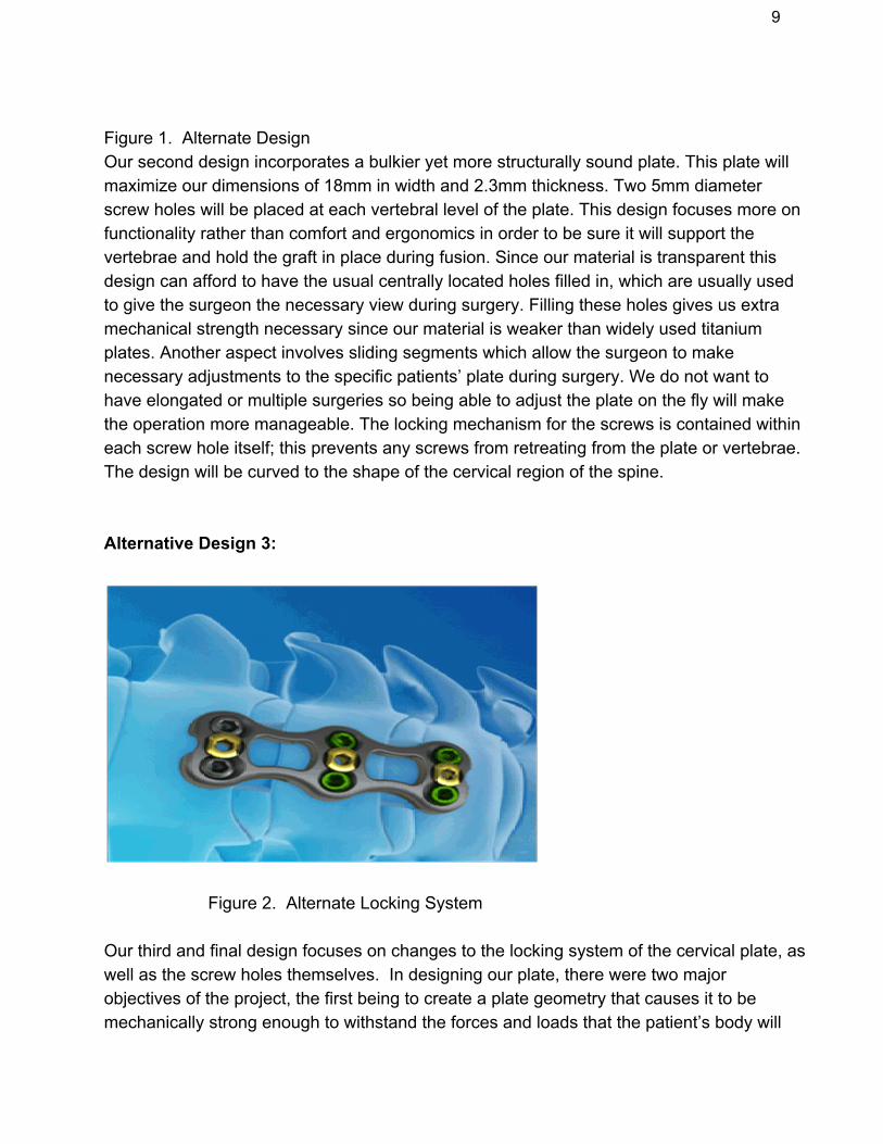
Figure 1. Alternate DesignOur second design incorporates a bulkier yet more structurally sound plate. This plate willmaximize our dimensions of 18mm in width and 2.3mm thickness. Two 5mm diameterscrew holes will be placed at each vertebral level of the plate. This design focuses more onfunctionality rather than comfort and ergonomics in order to be sure it will support thevertebrae and hold the graft in place during fusion. Since our material is transparent thisdesign can afford to have the usual centrally located holes filled in, which are usually usedto give the surgeon the necessary view during surgery. Filling these holes gives us extramechanical strength necessary since our material is weaker than widely used titaniumplates. Another aspect involves sliding segments which allow the surgeon to makenecessary adjustments to the specific patients’ plate during surgery. We do not want tohave elongated or multiple surgeries so being able to adjust the plate on the fly will makethe operation more manageable. The locking mechanism for the screws is contained withineach screw hole itself; this prevents any screws from retreating from the plate or vertebrae.The design will be curved to the shape of the cervical region of the spine.
Alternative Design 3:
Figure 2. Alternate Locking System
Our third and final design focuses on changes to the locking system of the cervical plate, aswell as the screw holes themselves. In designing our plate, there were two majorobjectives of the project, the first being to create a plate geometry that causes it to bemechanically strong enough to withstand the forces and loads that the patient’s body will

10
place on it. The second main objective was to create a locking system that would keep thescrews from backing out of the vertebrae while fusion occurs. This is a major point ofemphasis because most cervical plates are created using metals such as titanium.Because our design will be using a biodegradable polymer, the locking system must alsobe created with this polymer. This makes it imperative that the locking system is designedto be strong enough that it will not allow the screws to back out. Our first two designs focuson the first parameter, showing different possible geometry of the plate that could enhanceits mechanical strength, as well as other properties of the device. As this third designfocuses on the second main objective, it is important to note that it can use the plategeometry from either the first or second alternative design. While Figure 3 shows ageometry closer to alternative design 1, it is shown above only to give an illustration of adifferent possible locking system for the device. Instead of using six individual lockingsystems within each of the screw holes, this design uses only three locking systems, withone locking system being placed on each of the three vertebrae. The locking system in thefirst two designs works by locking each screw into place by rotating the locking device intoa position that the screw can no longer move. This alternative design works similarly, but isable to lock a pair of screws into place by simply rotating the locking system 90 degrees.Figure 3 shows the locking device in the locked position, but it can clearly be seen that byrotating the locking system, the screws will gain the ability to rotate freely. This alternativedesign could possibly be much more viable than individual locking systems for a fewreasons. Firstly, there are no constraints that would keep this from being possible,especially because the plate must be symmetric in order to balance the forces on the platefrom the body. Secondly, because the majority of the load placed on the plate will becentered at the screw holes, connecting each pair of screw holes with one locking systemcould help to balance and center the load a bit. This would make it much less likely for thedevice to fail because of its mechanical strength. Finally, because this design only useshalf the number of locking systems, it becomes easier to manufacture as well as much lesscostly. Along with changes to the locking system, this design will also look to possiblychange things about the screw holes themselves. Obviously, the holes are alreadychanging because there would no longer be a locking system within each hole, but thisdesign would also look to change the diameter of the screw holes as well. In the first twodesigns, the hole sizes are designed to accommodate 4mm screws. Because this devicewill be using a new material, the optimal screw size to use may very possibly differ from thestandard size used by other devices. Because of this, we will test different screw holesizes in this third alternative design. It will change from a 4mm screw to a 3mm or 5mmscrew in order to find the optimal size for this specific device. As the screw size will bechanging, the hole sizes will also be changed accordingly to fit the new screw size.
Our optimal design was chosen for a few different reasons. The most prevalent

11
goal of our project was to design our system to maximize the mechanical strength of thedevice so that it would be able to withstand the loads and forces placed on it by the bodyduring the fusion process. With that in mind, our optimal design most closely resembledthe second alternative design because it had the most sound structure and focused on themechanical strength of the device. It did away with the holes in the middle of the plate,which are common in cervical plates mostly so that the surgeon can have a better visualinto the body. Because our biodegradable polymer is transparent as opposed to titanium,which is the normal material used, there is really no need for the holes, and they would onlylower the mechanical strength of the material. With respect to the locking system, wechose to create the design with the intention of having six individual locking mechanisms,one for each of the screws that will be used. We decided to design our device in thisfashion because by using individual locking systems, each of the mechanisms only needsto support a single screw as opposed to having to hold multiple screws in place. Otherthan the cost reduction of using only half the amount of locking mechanisms, there wasn’tmuch of a reason to not use individual locking mechanisms, as they would clearly be betterwith respect to the mechanical strength of the overall device. While our optimal designdoes lean towards one of the alternative designs, there were aspects from each of thealternative designs and more that were incorporated into the optimal design.
2.2 Optimal Design
2.2.1 Objective
Our design is an approach to fixing the spine with a degradable plate followinganterior cervical spine surgery. When an intervertebral disc is herniated or bulged it canpress against the spinal nerve and cause severe pain for the patient. Anterior cervicalfusion surgery involves removal of the damaged disc followed by insertion of a bone graftor substitute that will fuse the vertebrae together. The plate is then screwed into the fusedvertebrae. Anterior plates were first introduced to aid in multilevel spinal fusion to fixate thegraft and spine but are now widely used in onelevel fusion to decrease recovery time fromthe procedure. The majority of plates still used today are made out of titanium which musteither be left in the patient permanently or require a second surgery. Our design hopes touse a novel polymer to create a biodegradable plate that stills meets the mechanicalproperties necessary for the plate.
To be certain our design meets the industry standards we will be utilizing ANSYSFEA program to design our plate and simulate the loads that it would undergo in the body.Our design must follow the natural curvature of the spine as not to prevent any naturalmotion. Other challenges we face include creating an integrated locking system for the
12
4mm screws to prevent them from backing out. The screws will be locked in place usingthe flexible properties of the polymer to snap into place. The new plate must not be largerthan the current plate design to prevent affecting the patients comfort prior to degradation.
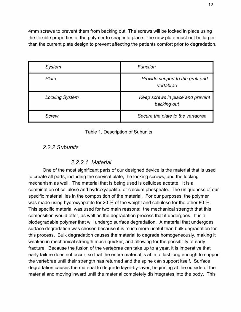
System Function
Plate Provide support to the graft andvertabrae
Locking System Keep screws in place and preventbacking out
Screw Secure the plate to the vertabrae
Table 1. Description of Subunits
2.2.2 Subunits
2.2.2.1 MaterialOne of the most significant parts of our designed device is the material that is used
to create all parts, including the cervical plate, the locking screws, and the lockingmechanism as well. The material that is being used is cellulose acetate. It is acombination of cellulose and hydroxyapatite, or calcium phosphate. The uniqueness of ourspecific material lies in the composition of the material. For our purposes, the polymerwas made using hydroxyapatite for 20 % of the weight and cellulose for the other 80 %.This specific material was used for two main reasons: the mechanical strength that thiscomposition would offer, as well as the degradation process that it undergoes. It is abiodegradable polymer that will undergo surface degradation. A material that undergoessurface degradation was chosen because it is much more useful than bulk degradation forthis process. Bulk degradation causes the material to degrade homogeneously, making itweaken in mechanical strength much quicker, and allowing for the possibility of earlyfracture. Because the fusion of the vertebrae can take up to a year, it is imperative thatearly failure does not occur, so that the entire material is able to last long enough to supportthe vertebrae until their strength has returned and the spine can support itself. Surfacedegradation causes the material to degrade layerbylayer, beginning at the outside of thematerial and moving inward until the material completely disintegrates into the body. This

13
allows for the device to last longer, as well as keeping its mechanical strength for a longeramount of time as well. Along with the process of how it degrades, this material was alsochosen because when it degrades, it has safe degradation products. Unlike manybiodegradable polymers, the cellulose acetate degrades into biocompatible products thatwill not cause any sort of inflammation or harm to the surrounding tissue or to the body.Because it is a biodegradable product, it is necessary to create all parts of the deviceusing the material, so that they all degrade simultaneously. Below, the chemical structureof cellulose acetate is shown in the form of a monomer.
Figure 3: Shows the chemical structure of cellulose acetate.
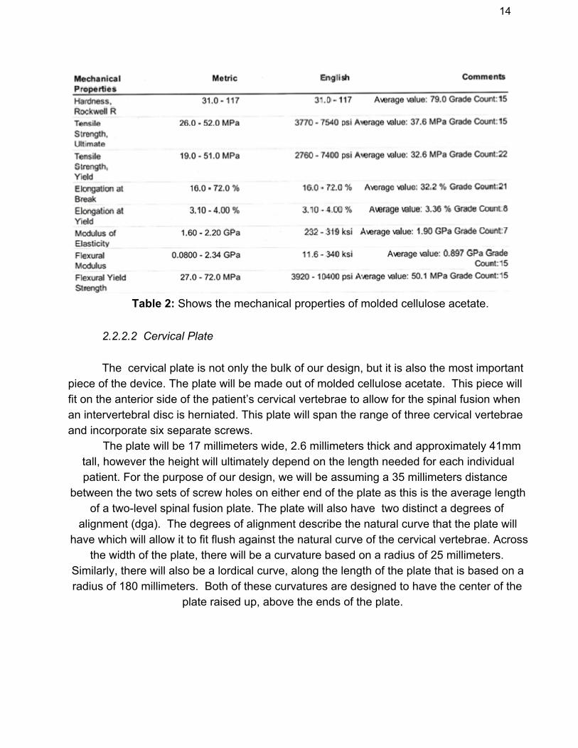
Below, a table is shown with the mechanical properties of the cellulose acetatematerial. These are very significant within our design as these values are used when doingsimulations to test the mechanical strength of the material.
14
Table 2: Shows the mechanical properties of molded cellulose acetate.
2.2.2.2 Cervical Plate
The cervical plate is not only the bulk of our design, but it is also the most importantpiece of the device. The plate will be made out of molded cellulose acetate. This piece willfit on the anterior side of the patient’s cervical vertebrae to allow for the spinal fusion whenan intervertebral disc is herniated. This plate will span the range of three cervical vertebraeand incorporate six separate screws.
The plate will be 17 millimeters wide, 2.6 millimeters thick and approximately 41mmtall, however the height will ultimately depend on the length needed for each individualpatient. For the purpose of our design, we will be assuming a 35 millimeters distance
between the two sets of screw holes on either end of the plate as this is the average lengthof a twolevel spinal fusion plate. The plate will also have two distinct a degrees of
alignment (dga). The degrees of alignment describe the natural curve that the plate willhave which will allow it to fit flush against the natural curve of the cervical vertebrae. Across
the width of the plate, there will be a curvature based on a radius of 25 millimeters.Similarly, there will also be a lordical curve, along the length of the plate that is based on aradius of 180 millimeters. Both of these curvatures are designed to have the center of the
plate raised up, above the ends of the plate.

15
.
Figure 4: Shows the curve along the width defined by a 25mm radius.
Figure 5: Shows the curve along the length defined by a 180mm radius.
The plate will feature two holes for the screws on each of the vertebrae. These holeswill be spaced 3.75 millimeters from the side of the plate, and will be 4.35 millimeters fromeither end of the plate with one set of screw holes lying directly on the midline of the plate.These holes will also be slightly tapered, with a smaller diameter on the bottom of the plateand a larger diameter on the top. This will allow the screw head to sit flush with the plateand eliminate any possible movement or shifting that could occur. On the distal side ofeach of the screw holes will be 1.52 millimeters of space.

16
Figure 6: Shows the location and layout of the screw holes on the plate.
At the midpoint between the sets of screw holes will be an additional hole which willbe situated directly on the midline of the plate. This hole serves two functions; it allows forthe surgeon to see and operate on the intervertebral discs while putting the plate in place,and secondly, it allows for more of the body’s fluids to reach the area where the fusion isgoing to take place. This allows for the hydroxyapatite to encourage the synthesis of bonemore rapidly. These holes will be 5.2 millimeters in diameter and will be hexagonallyshaped.

17
Figure 7:Highlights the location and dimensions of the mid cuts.
The last major innovation this design will feature is the inclusion of inlets located oneither side of the medial openings and between the two screw holes on both the top andthe bottom of the plate. The indents on the sides of the plate will be two millimeters deepand four millimeters long. The indents on the top and bottom of the plate will be 2millimeters deep and 3 millimeters wide. These indents would allow for the use of lessmaterial, saving money on the production of the plate. It would also allow for the surgeon tohave more space to operate when putting the plate into place.
Figure 8: Shows the design of the plate from the side view.

18
To test the design we will be using the program ANSYS Workbench. ANSYSprovides a fully functioning platform for building custom object and analyzing them. ANSYSWorkbench provides a framework for design exploration and optimization by enablingparametric modeling of geometric configurations, mesh controls, material properties, andoperating conditions, leading to an automated simulation process. It also serves as a fullfinite element analysis software. This allows the user to test the object when the system isstatic, dynamic and to also account for heat transfer. These properties make it an ideal toolto use for building our plate.
Figure 7: Shows the original plate design with the first ANSYS simulation

19
Figure 8: Shows a simulation with countersink width decreased to 0.2mm
Figure 9: Shows the simulation with sidecut depth decreased to 1.75mm

20
The three examples above show the different ways we were able to use ANSYS todetermine which of our designs would best meet our needs. By adjusting the thickness,width, and the differing sizes of the attributes we were able to determine what the bestdimensions. We will use ANSYS to test the mechanical limits and properties to ensure thatour design will be successful before it is ever made.
For our design to be successful, our client wished that the plate meet current marketstandards so that it can measure up to what other current cervical plates can do. Fos us,this meant we must first look at the mechanical properties of current plates used on themarket.
Ti6Al4V
Ultimate TensileStrength
950 MPa 183k psi
Ultimate Tensile Yield 880 MPa 128k psi
Elastic Modulus 114 GPa 16510k psi
Table 3: Shows the mechanical values for Biomet’s MaAn plate (titanium).
Table 3 shows the mechanical properties of a plate made of high grade titanium.These plates are exceptionally strong and are able to withstand more than the necessaryforce required to support the spine during fusion. These are the most commonly usedplates currently due to their durability. Unfortunately, these plates are not biodegradableand are permanently implanted into the patient. We took these numbers as a high point forwhat our plate must withstand as most doctors say the strength far exceeds what is neededto support the vertebrae.
PLLA/PDLA
Ultimate TensileStrength
45 MPa 6530 psi
Ultimate YieldStrength
5% 5%
Elastic Modulus 3 GPa 435k psi
Table 4: Shows the mechanical values for Inion’s Plate which is biodegradable (polymer).

21
Table 4 shows the mechanical properties of a biodegradable plate that is currentlyon the market and has been approved by the FDA. This plate has been used in patientsbut is not favored by doctors due to the fact that it is not quite strong enough to support theload it needs to and because the components it degrades into can be harmful to the spinalarea. For this reason, we took these to be an absolute minimum standard for our plate tomeet in order to be successful.
For our plate, we want to at least match the numbers for ultimate tensile strength,ultimate yield strength and elastic modulus of the Inion plate. Ideally, we would like to seeour plate exceed the numbers of the Inion plate and have an ultimate tensile strength ofaround 90 MPa, an ultimate yield strength of 10%, and an elastic modulus of 6 GPa. Onceagain, those numbers are an ideal desire; the plate must only meet the numbers that thecurrent Inion plate has to be viable for use on the open market.
In order to test and compare our own plate to current plates on the market, our clientprovided us with an ANSYS simulation that was run on a competing plate made by thecompany Inion. We were able to use our own design and run an equivalent analysis. Indoing this, we were able to compare the results of our product versus a competing product,in simulation at least. This will give us the information needed to determine whether ourplate will be viable to be used on the market or whether it needs to be further optimized.
2.2.2.3 Locking System
While the cervical plate is the base of the device, there are a few differentaccessories that are attached to the cervical plate that are essential to its function. Themost important of these accessories is the locking system for the screws that keep thevertebrae in place while fusion is occurring. The locking system is meant only to keep thescrews from moving during the time of implantation. This is necessary because one of themajor issues and concerns with the cervical plate is keeping the system locked in place. Ifthe plate were to come loose before fusion of the vertebrae is fully completed, there is avery good possibility that the vertebrae would also become loose and not allow the discs tofully regenerate as they are meant to. There are a few different ways in which the cervicalplate could lose its tight hold on the vertebrae in the spinal cord including things such asearly fracture to the plate, but the most common problem during the fusion process is forthe screws to back out of the vertebrae they are attached to. If the screws back out of thevertebrae, it is normally due to the fact that the locking system has failed because thelocking system’s only true function is to hold the screws in the correct location.
In order to hold the screws in place, six locking mechanisms are included in the
22
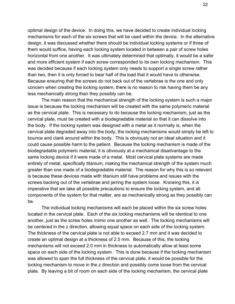
optimal design of the device. In doing this, we have decided to create individual lockingmechanisms for each of the six screws that will be used within the device. In the alternativedesign, it was discussed whether there should be individual locking systems or if three ofthem would suffice, having each locking system located in between a pair of screw holeshorizontal from one another. It was ultimately determined that optimally, it would be a saferand more efficient system if each screw corresponded to its own locking mechanism. Thiswas decided because if each locking system only needs to support a single screw ratherthan two, then it is only forced to bear half of the load that it would have to otherwise.Because ensuring that the screws do not back out of the vertebrae is the one and onlyconcern when creating the locking system, there is no reason to risk having them be anyless mechanically strong than they possibly can be.
The main reason that the mechanical strength of the locking system is such a majorissue is because the locking mechanism will be created with the same polymeric materialas the cervical plate. This is necessary to do because the locking mechanism, just as thecervical plate, must be created with a biodegradable material so that it can dissolve intothe body. If the locking system was designed with a metal as it normally is, when thecervical plate degraded away into the body, the locking mechanisms would simply be left tobounce and clank around within the body. This is obviously not an ideal situation and itcould cause possible harm to the patient. Because the locking mechanism is made of thebiodegradable polymeric material, it is obviously at a mechanical disadvantage to thesame locking device if it were made of a metal. Most cervical plate systems are madeentirely of metal, specifically titanium, making the mechanical strength of the system muchgreater than one made of a biodegradable material. The reason for why this is so relevantis because these devices made with titanium still have problems and issues with thescrews backing out of the vertebrae and jarring the system loose. Knowing this, it isimperative that we take all possible precautions to ensure the locking system, and allcomponents of the system for that matter, are as mechanically strong as they possibly canbe.
The individual locking mechanisms will each be placed within the six screw holeslocated in the cervical plate. Each of the six locking mechanisms will be identical to oneanother, just as the screw holes mimic one another as well. The locking mechanisms willbe centered in the z direction, allowing equal space on each side of the locking system.The thickness of the cervical plate is not able to exceed 2.7 mm and it was decided tocreate an optimal design at a thickness of 2.5 mm. Because of this, the lockingmechanisms will not exceed 2.0 mm in thickness to automatically allow at least somespace on each side of the locking system. This is done because if the locking mechanismwas allowed to span the full thickness of the cervical plate, it would be possible for thelocking mechanism to move in the z direction and possibly come loose from the cervicalplate. By leaving a bit of room on each side of the locking mechanism, the cervical plate

23
will be able to press down on each side of the locking system, essentially constraining it inplace.
The locking systems will follow the shape of the screw holes that they will be locatedin. The screw holes are designed to accommodate 4.0 mm screws. Because of this, thediameter of the screw holes, and thus the locking mechanisms, are a little greater than 4millimeters. The locking systems will also rotate fully around the screw hole, allowing thelocking mechanism to complete 360 degrees of rotation. In using the locking mechanism,the main necessity is to create a system in which there is a locked and unlocked position.While in the locked position, the screw is unable to rotate in either direction and is heldstably. While in unlocked position, the screw is able to rotate in both directions, screwinginto or out of the vertebra. During the procedure, the surgeon will have to screw the lockingscrews into the vertebrae to lock the system into place. As the screws approach their finallocation, they will also move the locking system and click it into the locked position. Oncethis has occurred, the screws will not be allowed to move in a counterclockwise direction,making it impossible for the screws to back out of the vertebrae.
In the end, we created a few different possible locking mechanisms that allfollow the constraints listed above. We were not able to actually implement the lockingmechanism into our device because of manufacturing methods, but the theoretical designscan all be utilized if the product continues past this design process. One of the mostpopular locking mechanism design incorporates expansionhead screws. These work byhollowing out the screw head. This allows a second screw to enter the primary screw androtate to lock both pieces into place. While accurate and functional, we also createdsimpler designs in case this was found to be too expensive or difficult to procure. The firstdesign we created is a notched locking mechanisms, with a pattern of slots cut into the topof the system. With male counterparts on the screw head, it will allow the screw notches tofall into the slots and lock into place. The second possibility is a slotted locking mechanismthat has a slot cut horizontally through almost two thirds of the locking system. This causesthe part to slightly compress in on itself. When the screw is tightened within the lockingmechanism though, it causes the locking system to return to original form using tension.This is able to lock the screw in place, with the locking mechanism gripping it in place,utilizing mostly frictional forces to do so. These designs are much simpler and would bemuch cheaper to manufacture, but have not been tested and shown to be functionallyequivalent to current locking mechanisms on the market.
2.2.2.4 Locking Screws
The locking screws for this system are provided by our client. The screws are 4 mmin diameter with six full threads, roughly being 15 mm in length. They also have a head that

24
is 5 mm in diameter and is 2 mm in thickness. These screws are self tapping, whichmeans that they do not require a predrilled hole. They can be immediately screwed intothe vertebrae with no previous work done and will thread the hole themselves as they moveinto the vertebrae of the spine. We will need to take into account both the screw hole size,placement of the screw holes, and the possible trajectory the screw will take into thevertebrae. Along with this, the design of the locking mechanism will obviously have to bebased upon the screw and screw hole size. The plate will consist of two screw holes perlevel, having six overall holes. The screw holes will be countersunk so that the screws willbe flush with the plate throughout. The holes will be placed in the further mechanicallycorners and edges of the plate as to allow for maximum mechanical strength toward theinside of the plate. Currently, the screws will be drilled perpendicular to the plate, but it ispossible to have a different trajectory in order to increase the security and have a betterentry angle into the vertebrae. Previous designs using titanium for the plate materialinvolve a trajectory which is used to help prevent the screws from backing out of thevertebrae. Another aspect to the screw is the possibility of either unicortical or bicorticalinsertion. Unicortical is only drilled partially through the vertebrae, while bicortical drills thefull distance. [1] Previous studies have been performed and show that bicortical insertioncauses an increase in strength, but it is in question due to the risks posed by the bicorticalscrew interfering with the internal carotid artery.
2.3 Prototype
2.3.1 Spinal Fusion PlateAfter the initial design of the cervical spinal fusion plate was created, it next needed
to be enhanced, in order to improve its mechanical strength and match the properties ofother plates on the market currently. In order to do this, we began by breaking down all ofthe different parameters that make up the cervical plate. While there are some geometricalconstraints that must remain in place and cannot be changed, there are many that can bevaried and cause changes to the mechanical strength of the overall device. By optimizingall of the different parameters of the plate, it allows the mechanical properties of the deviceto be enhanced as much as possible within the CAD program.
The first parameter that we began to optimize was the length of the sidecuts. Alongthe length of the plate, there are two rectangular cutouts on either side of the plate. Theseare necessary in order to distribute the loads and forces placed on the plate. A simplerectangular plate is not a possibility because of many reasons such as the distribution ofloads, the comfortability of the patient, and safety hazards. Rectangular cut outs werechosen due mostly to the fact that they remove the smallest amount of material from thedevice, which allows mechanical strength of the plate to be maximized. We redesignedand simulated our plate using a range of side cut lengths in order to determine the optimum

25
length for our design. Below, a table shows the different side cut lengths that were tested.Along with this, the maximum equivalent von Mises stress is shown for each simulation.The von Mises stress shows the overall deformation of the plate, and is the variable that weare using to compare our plate to that of other competitive plates.
Side cut Length (mm) Max von Mises Stress (psi)
5.2 20047
5.6 20569
6 21204
6.2 21416
6.4 21697Table 5. Side cut Length Optimization
Looking at the table, it shows that as the length of side cut is decreased, themaximum von Mises stress is as well. Because of this, we chose the lowest possible sidecut we were able to incorporate into the device, which is 5.2 millimeters. The simulation atthis length is shown below:
Figure 10. 5.2 mm side cut length

26
Similarly to the side cut length, we then optimized the side cut depth. This showsthe distance the side cut extends into the body of the plate. Again, we tested the plate witha range of depths, and found the optimal level. The testing results are shown below, withan optimal side cut depth of 1.0 millimeters being chosen.
Side cut depth (mm) Max Von Mises (psi)
2 21204
1.8 21268
1.6 20947
1.4 20616
1.2 20204
1.0 19904Table 6. Side cut depth
The next parameter that was optimized was the thickness of the plate. Becauseincreases in the thickness of the plate causes discomfort to the patient, it cannot exceed2.7 millimeters. Similar tests to other parameters were done, but the optimal thicknesswas not chosen strictly based on mechanical strength.
Plate thickness (mm) Max von Mises (psi)
2.3 21204
2.4 19703
2.5 18917
2.6 15661
2.7 16893Table 7. Thickness
An optimal level of 2.5 millimeters was chosen even though it was not the lowest vonMises stress. This is due to the fact that while allowable, higher values still run the risk ofcausing discomfort. Due to the fact that our design has been optimized past its goal, wewere able to choose a lower value to ensure comfortability, while still retaining thenecessary mechanical properties for proper functionality.

27
The final noteworthy parameter that was optimized was the center cuts locatedbetween the pairs of screw holes, in the middle of the plate widthwise. These holes arenecessary for the surgeon to have visibility of the vertebrae and intervertebral discs duringthe surgical procedure. Because they are used simply for vision, there are no shapeconstraints, only the constraint of needing to be large enough to provide a viewing area.Knowing this, we tested different shapes to use for center cuts, testing the von Misesstress. Results are shown below:
Cut Shape Max von Mises stress (psi)
Triangle 21204
Circle 19703
Square 18914
Hexagon 19345Table 8. Center cut shape
With these results, we chose a square shape for our model. Along with providingthe plate with the greatest mechanical properties, it also was able to distribute the loadsand forces more efficiently than any of the other shapes, which will be helpful in reducingthe risk of cracks and fractures.
After we were able to optimize all of the different parameters, we combined theminto a final model. While having all of these parameters incorporated into a single device,the von Mises stress was very significantly reduced, showing the enhancement of themechanical properties of the cervical plate. After this, they were again reoptimized toensure that the optimal levels were not changed because of the changes in otherparameters. With our spinal fusion plate fully optimized and well beyond our goal for themaximum von Mises stress, we began manufacturing of the plate.
Our initial plan had been to use either compression or injection molding tomanufacture our prototype of our plate, as this is the most optimal way to create thesespinal fusion plates. Unfortunately, compression molding was not able to be used becausethere was no access to one. Injection molding also was not possible because of monetaryrestrictions based on the budget of the project. Due to this, we were forced to attempt tomachine the cervical plate ourselves, using a milling machine. We received a block ofcellulose acetate from our client and attempted to manually manufacture the plate.Unfortunately, it was not possible to do because of the precise geometry of the plate, alongwith the brittle nature of the material. On multiple attempts, cracks propagated and causedthe plate to snap during the milling process. Because of the very small dimensions used

28
within the plate, along with the fact that the material is not extremely strong to begin with,manual machining simply was not an option.
In response to this, we were able to gain access to a 3D printer that was capable ofcreating a prototype of our plate out of PLA fibers. While it is not the exact material that willbe used for this fusion plate, it is still a viable prototype for testing. This is because we areable to run simulations using FEA testing in ANSYS using the properties of the PLAfilament. With this, we are still able to validate our design of the plate by testing theprototype similarly. Along with this, it also allows us to more closely compare our model tothat of the competing Inion plate. The 3D printer used was a MakerBot: Replicator 2. Apicture of the manufactured prototype is shown in the figure below:
Figure 11. 3D printed prototype
For the testing of the plate, we first had to verify that our design was acceptable andthat it matched up to the properties of our prototype. In order to do this, we performed athreepoint bending test on our 3D printed model. A TiniusOlsen machine was used toperform the testing of the prototype. The model was placed on two balance points, while athird part was pressed down onto the center of the plate. In doing this, it caused the plateto bend until it finally fractured and failed. A graph of the results is shown below:

29
Figure 12. 3Point bend test
The results of the test showed that fracture occurred at a force of 114.63 Newtons.This force was applied to the spinal plate after a displacement of 2.25 millimeters. In orderto compare these results to that of our CAD design, we ran an identical simulation withinthe FEA testing of ANSYS. The 3point bending test was mimicked and a force of 114.63Newtons was placed upon the plate. The analysis is shown below:
Figure 13. ANSYS 3point bed

30
As the results show, the maximum displacement is shown to be around 2.8millimeters. Looking at these results comparatively to our 3D printed model, it shows aclose similarity and verifies the validity of our design. The difference in value is most likelyaccounted for by slight differences in the mechanical properties of the PLA fibers used forthe prototype and that inputted into the ANSYS simulation. Once the design of the devicewas verified, standard testing could begin in order to move closer to public exposure of theproduct. ASTM F1717 requirements were followed, as they pertain to spinal implantconstruct biaxial testing. The model was analyzed based on four different testing methods:compression, tension, torsion, and fatigue.
3.0 Realistic Constraints
3.1 Economic ConstraintsThere are many different constraints that must be considered when designing the
cervical plate device. Economically, there are not too many factors because it is a veryinexpensive project overall. The only thing that must be limited is the number ofmanufactured devices for testing purposes. Because the plates must be designedindividually for patients, many different lengths and sizes of devices must be tested toensure that they will all efficiently work. This will be done by using the program ANSYS.Within the program, we are able to create, test, and analyze the mechanical strength of thecervical plate using any different geometry that might possibly be needed.
3.2 Environmental ConstraintsWhen dealing with environmental constraints, the main concern is ensuring that the
device is biocompatible and will not cause any adverse reactions from the host tissue. Thematerial being used to create all parts of the device is a biodegradable polymer that ismade up of mostly cellulose, along with hydroxyapatite. Both of these materials arebiocompatible and will not cause any negative effects from the body. Along with the initialmaterial being biocompatible, it must also not cause any adverse reactions from the bodyas the polymer degrades. The polymer chosen for the design also has biocompatibledegradation products to address this issue and make sure that the body does not reactnegatively at any time.
3.3 Sustainability ConstraintsAnother major constraint that needs to be considered is sustainability of the device.
All parts of the device must remain intact until the vertebrae have fully fused. Fusionnormally takes up to one year to occur so the polymer must not degrade for at least thislong. The amounts of cellulose and hydroxyapatite combined were used in order to ensure

31
that the polymer would last for a long enough time. Along with this, the polymer alsoundergoes surface degradation as opposed to bulk degradation. Bulk degradation canlead to early failure of the device because the entire material degrades at the same time,making a fracture or break possible. Surface degradation removes the outer layer first andslowly degrades to the middle of the material, sustaining the mechanical integrity of thematerial for a longer period of time.
3.4 Manufacturing ConstraintsThe foremost manufacturing constraint, spoken about briefly above, is the
necessary variability of the size and dimensions of the cervical plate. Because all peopleare unique and have different attributes such as height, the distance between vertebrae inthe spine changes from person to person. To account for this, the length of the cervicalplate and its overall geometry must be changed to make sure that the screws of the deviceare positioned in the correct location. The second manufacturing constraint to consider isthe actual process of manufacturing the device. Based on the material and the designparameters, the device will be manufactured by either injection molding or compressionmolding.
3.5 Ethical ConstraintsThere are not really any concerning ethical constraints that pertain to the design of
our device. Ethically, the only constraint is to ensure that our group creates a safe andhealthy product for the public, but these issues will be covered below in the health andsafety section. Otherwise, the only ethical concern that may arise would be during possiblein vitro and in vivo testing of the product. Regardless of what negative effects it would haveon the release of our product, it is an engineer’s ethical responsibility to report any and alltesting results. While we do not plan or expect any negative side effects to occur duringtesting, anything can happen during the process and that is the reason that testing of theproduct is necessary to begin with. If anything were to happen, the food and drugadministration (FDA) would be notified to ensure that we act in an ethical manner.
3.6 Health and Safety ConstraintsIt is extremely important to ensure that the health and safety of the patient is being
considered. This begins by making sure that the cervical plate system is properly cleanedand sterilized before it is implanted in the body during surgery. Also, as discussed above,the material being used is biocompatible and is very safe to implant into the body. Alongwith this, the cervical plate must be designed so that there is no discomfort for the patientwhile it remains in the body. In order to do this, the plate is designed to be quite thin.Patients seem to feel discomfort whenever the plate thickness is greater than or equal to 3mm. Because of this, the optimal design parameters do not allow the cervical plate to

32
exceed 2.7 mm. The cervical plate is also designed to have no sharp edges or anythingthat could poke and prod the patient to cause any discomfort.
3.7 Social ConstraintsWe have not found any social constraints that would pertain to our cervical plate
device. None of the materials that are used to create the cervical plate are objectionableto people in the general public. They are not materials that are debated such as the use ofstem cells, for example. The surgical procedure and use of cervical plates to curedegenerative disc disorder are also not objectionable to the general public as far as weknow.
3.8 Political ConstraintsFinally, political constraints must be considered when designing the device.
Possibly the most important constraint, the cervical plate must get the FDA to approve itbefore it can be placed on the market. The FDA has long and rigorous testing that amedical device must pass before they will allow the device to be used on the generalpublic. This will normally include in vitro testing as well as in vivo testing to ensure that thedevice is safe and has no negative side effects.
4.0 Safety Issues
Many of the common safety issues are not relevant to our project because thecervical plate design does not contain the necessary components to cause these possiblehazards. For example, there are no circuit boards or electrical work within the design, andtherefore, there are no electrical safety issues. The main safety issue that our design mustaccount for is mechanical safety issues. The cervical plate must be able to withstand themechanical forces and loads that the body places on the plate during the time of fusion. Ifthe plate is not mechanically strong enough, fracture could occur due to the forces andstresses of the body. This is obviously a main safety issue with the cervical plate becausethe vertebrae would not be able to stay in place if fracture occurred, leading to fusion nottaking place.
Similarly, the locking system must also be mechanically strong enough to hold thescrews in place in the vertebrae. A common problem that occurs during fusion is thescrews backing out of the vertebrae, causing the entire device to loosen and fall out ofplace. This is due to the locking system either accidentally rotating into the unlockedposition or not being mechanically strong to hold the screws in place.
Other than mechanical issues, the only other safety issues involve the host reactionto biomaterials as well as the degradation of the device. Unlike the majority of cervical

33
plates on the market, which use metals such as titanium, our design uses a biodegradablepolymer that is made up of cellulose and hydroxyapatite. Both of these materials arebiocompatible, so there will be no host reaction to the device. The design must alsoensure that there will not be a host reaction to the device while it degrades. The polymerbeing used undergoes surface degradation as opposed to bulk degradation. When apolymer undergoes surface degradation, it slowly erodes, starting with the surface of thematerial and slowly removes layer after layer until the entire material has degraded. This ismuch safer than using a polymer that undergoes bulk degradation because bulkdegradation can lead to early fracture and failure before fusion has fully occurred.Whenever using a material that is biodegradable, there is a safety issue involving the hostreaction to the degradation products of the original material. The biodegradable polymerbeing used for the cervical plate device degrades away into biocompatible products.Therefore, there will not be a negative host reaction to the biodegradable polymer or to thedegradation products of the material. When considering thermal safety issues, there is nocause for concern as the device only has to withstand normal body temperatures, which thepolymeric material is easily capable of doing. There are no safety issues regarding thingssuch as chemical hazards or radiation.
5.0 Impact of Engineering Solutions
With the creation of this new cervical plate design, there will be an impact fromengineers to the medical world as well as to the general public. There is a lot of room fornew applications because of the material that is being used for the cervical plate design. Itis a fairly new polymer that has been patented by our client. This means that as of rightnow, it is not able to be used by the rest of the general public. Knowing this, it shows thepossibilities of being used in a multitude of different ways within the engineeringcommunity.
The material used to create the cervical plate is made up of cellulose andhydroxyapatite, but more importantly, it undergoes surface degradation and breaks downinto biocompatible and harmless products. Within the field of cervical plate systems, thereare a few that use biodegradable polymers; the majority of these are made up of polylacticacid (PLA) and polyglycolic acid (PGA). There are two major advantages of thebiodegradable polymer used on our device that can cause a major impact within the field.Firstly, PLA and PGA based biodegradable polymers undergo bulk degradation ratherthan surface degradation. Because this causes the entire material to degrade at the sametime rather than degrading layerbylayer from the outside, it allows for the possibility thatthe device will fracture before it is meant to. Surface degradation is a much more useful

34
property within this field, as well as with other applications such as drug delivery. Thesecond advantage of the polymer we have used for our optimal design is that thedegradation products of the polymer are harmless and biocompatible. Polylactic acid andpolyglocolic acid have acidic degradation products that can cause a host reaction whenthe material degrades.
Another major impact that may be caused by this device is the fact that it can savetime and money for the general public and medical facilities. Right now, the majority ofcervical plate systems that are placed in patients are made of a metal, such as titanium.Because this is a nondegrading material, it means that once fusion of the vertebrae hasfully occurred, the patient must either undergo a second surgery to remove the device orthey must decide to simply continue living with a titanium plate attached to their spinal cord.Using a safe, biodegradable polymer such as the one being used in our optimal design,this is no longer an issue. The cervical plate and screws will simply degrade away into thebody after fusion has occurred, making it unnecessary for patients to spend the money on asecond surgery, as well as not requiring the hospital and doctor to take the time and moneyto perform the extraneous procedure.
All of these applications are realistic prospects for the cervical plate device once itis completed. The device in itself has the possibility of becoming the new standardprocedure for curing degenerative disc disorder with a plate implant. Along with this, thematerial used to create the device has many possible applications that have not beendiscovered yet, as it is a newly used polymeric material that has only been researched forits applications to this field of study so far.
6.0 Lifelong Learning
Researching and beginning to design this project has taught us a multitude ofknowledge, as well as engineering techniques that were not previously known. We firstlylearned about the background of cervical plate implants and the reason why they arenecessary. The implants are needed because of degenerative disc disorder, or DDD,which is a disease that can cause extreme pain and discomfort for people as the vertebraldiscs in their spine degrade. Degradation of the vertebral discs can happen because oftrauma, but it will occur over the course of a person’s life regardless of what precautionsare taken. While time will automatically take its toll on a person’s vertebrae as well as therest of the body, only a portion of people will suffer from degenerative disc disorder. Whena person does suffer from the disorder though, a cervical plate and screws such as the one
35
designed by our team must be implanted to hold the vertebrae of the spine together,allowing them to fuse to one another and create a stronger attachment. We have learnedabout the current techniques used to create cervical plates and the main concerns andissues that are problematic within the field at this time as well.
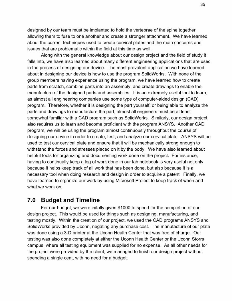
Along with the general knowledge about our design project and the field of study itfalls into, we have also learned about many different engineering applications that are usedin the process of designing our device. The most prevalent application we have learnedabout in designing our device is how to use the program SolidWorks. With none of thegroup members having experience using the program, we have learned how to createparts from scratch, combine parts into an assembly, and create drawings to enable themanufacture of the designed parts and assemblies. It is an extremely useful tool to learn,as almost all engineering companies use some type of computeraided design (CAD)program. Therefore, whether it is designing the part yourself, or being able to analyze theparts and drawings to manufacture the part, almost all engineers must be at leastsomewhat familiar with a CAD program such as SolidWorks. Similarly, our design projectalso requires us to learn and become proficient with the program ANSYS. Another CADprogram, we will be using the program almost continuously throughout the course ofdesigning our device in order to create, test, and analyze our cervical plate. ANSYS will beused to test our cervical plate and ensure that it will be mechanically strong enough towithstand the forces and stresses placed on it by the body. We have also learned abouthelpful tools for organizing and documenting work done on the project. For instance,having to continually keep a log of work done in our lab notebook is very useful not onlybecause it helps keep track of all work that has been done, but also because it is anecessary tool when doing research and design in order to acquire a patent. Finally, wehave learned to organize our work by using Microsoft Project to keep track of when andwhat we work on.
7.0 Budget and TimelineFor our budget, we were initally given $1000 to spend for the completion of our
design project. This would be used for things such as designing, manufacturing, andtesting mostly. Within the creation of our project, we used the CAD programs ANSYS andSolidWorks provided by Uconn, negating any purchase cost. The manufacture of our platewas done using a 3D printer at the Uconn Health Center that was free of charge. Ourtesting was also done completely at either the Uconn Health Center or the Uconn Storrscampus, where all testing equipment was supplied for no expense. As all other needs forthe project were provided by the client, we managed to finish our design project withoutspending a single cent, with no need for a budget.

36
Task Name Duration Start Finish
Alternative DesignResearch
7 Mon 9/24/12 Tue 10/2/12
Market ProductResearch
5 Mon 9/24/12 Fri 9/28/12
Patent Research 5 Wed 9/26/12 Tue 10/2/12Geometry LituratureResearch
5 Wed 9/26/12 Tue 10/2/12
ASTM Research 5 Tue 9/25/12 Mon 10/1/12Optimal Design 7 Wed 10/10/12 Thu 10/18/12Material Design inANSYS
2 Wed 10/10/12 Thu 10/11/12
ANSYS Tutorials 2 Wed 10/17/12 Thu 10/18/12Plate Design inANSYS
20 Wed 10/17/12 Tue 11/13/12
SolidWorksTutorials
8 Wed 10/17/12 Fri 10/26/12
Plate Design inSolidWorks
8 Wed 10/17/12 Fri 11/23/12
Original DimensionANSYS Simulations
2 Tue 11/13/12 Wed 11/14/12
Plate ProcessingResearch
4 Wed 10/24/12 Mon 10/29/12
Final Report Part 1 6 Wed 10/3/12 Wed 10/10/12IndividualParameterSimulations(SidecutDepth)
3 Thu 11/15/12 Mon 11/19/12
IndividualParameterSimulations(SidecutWidth)
3 Tue 11/20/12 Thu 11/22/12
IndividualParameterSimulations(PlateThickness)
3 Fri 11/23/12 Tue 11/27/12

37
Final Report part 2 6 Wed 10/17/12 Wed 10/24/12Final Report Part 3 6 Wed 11/14/12 Wed 11/21/12Scale PrototypeMachining
3 Mon 11/26/12 Wed 11/28/12
Scale PrototypeTesting
1 Thu 11/29/12 Thu 11/29/12
Realistic ForcesResearch
4 Mon 11/12/12 Thu 11/15/12
4900 SemesterPresentation
1 Mon 12/3/12 Mon 12/3/12
IndividualParameterSimulations(EndcutDepth)
3 Thu 1/3/13 Mon 1/7/13
IndividualParameterSimulations(EndcutLength)
3 Thu 1/10/13 Mon 1/14/13
IndividualParameterSimulations(Countersink width)
3 Mon 1/14/13 Wed 1/16/13
IndividualParameterSimulations(PlateWidth)
3 Tue 1/22/13 Thu 1/24/13
Optimal Platesimulationscombining 2parameters
2 Fri 1/25/13 Mon 1/28/13
Optimal Platesimulationscombining 3parameters
2 Tue 1/29/13 Wed 1/30/13
Optimal Platesimulationscombining 4
2 days Thu 1/31/13 Fri 2/1/13

38
parametersOptimal Platesimulationscombining 5parameters
2 Sat 2/2/13 Mon 2/4/13
Optimal Platesimulationscombining 6parameters
2 Mon 2/4/13 Tue 2/5/13
Optimal Platesimulationscombining 7parameters
2 Tue 2/5/13 Wed 2/6/13
Plate CompressionMolding processing
7 Mon 2/11/13 Tue 2/19/13
Prototype TorsionTesting
3 Mon 2/25/13 Wed 2/27/13
Prototype 3pointBending Testing
3 Mon 2/25/13 Wed 2/27/13
Prototype TensileTesting
3 Mon 2/25/13 Wed 2/27/13
Locking mechanismDesign
7 Fri 3/1/13 Mon 3/11/13
Locking MechanismANSYS
3 Tue 3/12/13 Thu 3/14/13
Locking mechanismprototype
1 Mon 3/18/13 Mon 3/18/13
Locking MechanismTesting
1 Thu 3/21/13 Thu 3/21/13
Locking ScrewsDesign
7 Fri 3/1/13 Mon 3/11/13
Locking ScrewsANSYS
3 Tue 3/12/13 Thu 3/14/13
Locking ScrewsPrototype
1 Mon 3/18/13 Mon 3/18/13
Locking ScrewsTesting
1 Thu 3/21/13 Thu 3/21/13
39
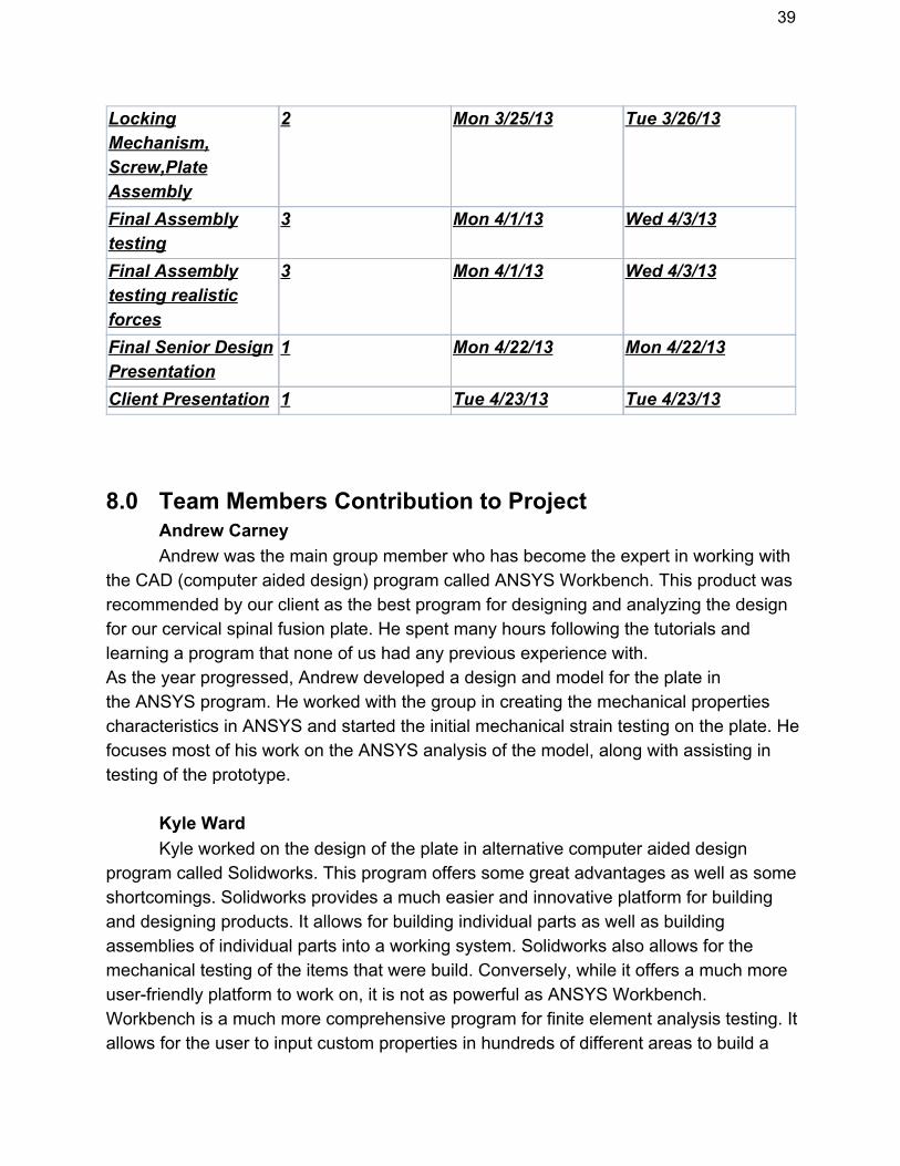
LockingMechanism,Screw,PlateAssembly
2 Mon 3/25/13 Tue 3/26/13
Final Assemblytesting
3 Mon 4/1/13 Wed 4/3/13
Final Assemblytesting realisticforces
3 Mon 4/1/13 Wed 4/3/13
Final Senior DesignPresentation
1 Mon 4/22/13 Mon 4/22/13
Client Presentation 1 Tue 4/23/13 Tue 4/23/13
8.0 Team Members Contribution to ProjectAndrew CarneyAndrew was the main group member who has become the expert in working with
the CAD (computer aided design) program called ANSYS Workbench. This product wasrecommended by our client as the best program for designing and analyzing the designfor our cervical spinal fusion plate. He spent many hours following the tutorials andlearning a program that none of us had any previous experience with.As the year progressed, Andrew developed a design and model for the plate inthe ANSYS program. He worked with the group in creating the mechanical propertiescharacteristics in ANSYS and started the initial mechanical strain testing on the plate. Hefocuses most of his work on the ANSYS analysis of the model, along with assisting intesting of the prototype.
Kyle WardKyle worked on the design of the plate in alternative computer aided design
program called Solidworks. This program offers some great advantages as well as someshortcomings. Solidworks provides a much easier and innovative platform for buildingand designing products. It allows for building individual parts as well as buildingassemblies of individual parts into a working system. Solidworks also allows for themechanical testing of the items that were build. Conversely, while it offers a much moreuserfriendly platform to work on, it is not as powerful as ANSYS Workbench.Workbench is a much more comprehensive program for finite element analysis testing. Itallows for the user to input custom properties in hundreds of different areas to build a

40
custom material.For this reason, Kyle worked to build the model in Solidworks and then import it
into ANSYS Workbench for strain testing. Importing into ANSYS kept presenting issues,so the mechanical testing was performed in Solidworks. While the ideal material couldnot be synthesized in Solidworks, the testing was performed in order to minimize thepeak von Mises in the material being used.As the final form of the plate takes shape, Kyle has taken an active role in manufacturingthe plates, taking care of the 3D printing of the parts.
Casey McDermottCasey acted as the jack of all trades for this senior design group. Early on,
Casey assisted Andrew in the initial understanding and building in the ANSYSWorkbench program. Having worked all summer at an internship where he had to workwith a similar computer aided design program, ProEngineer, Casey was able to provideinvaluable knowledge on basic workings and operations in Workbench.Casey also assisted Kyle on the design and building of much of his Solidworksdesign. After much of a struggle working on the plate without being able to correctlybend the plate, Casey came up with the idea to use alternate plans for building toconstruct a mesh of the plate and build it by connecting the planes together.In addition to all of the assistance provided on the design of both the ANSYS andSolidworks plates, Casey provided much of the background research as well as designingthe possible locking mechanisms that could be used. Along with this, he worked tomanage the group, as well as assisting in the testing of the product.
9.0 Conclusion
Throughout the process of our design project, we have created a suitable design fora cervical plate system. The plate system is used to hold a bone graft in place in order torepair damaged intervertebral discs. This is extremely useful in curing degenerative discdisease, or DDD. The cervical plate consists of three levels, allowing screws to enter intothree different vertebrae. This will allow the system to hold the graft in place for the time offusion before degrading away into the body. Two screws will enter each of the vertebraethrough the screw holes located in the cervical plate. The screws being used are standardfour millimeter screws made out of cellulose acetate. They are selftapping screws andthere will be a total of six screws incorporated into the device. There will also be a lockingmechanism that is used to keep the screws in place and not allow them to back out of thevertebrae during the time of fusion. In the device are six individual locking systems located

41
within each of the screw holes. These locking mechanisms will lock into place when thescrews are fully screwed into the vertebrae and not allow the screws to rotate or turn, whichwould allow them to unscrew and back out of the vertebrae. We have designed a cervicalplate with the maximum mechanical strength possible, using the CAD programsSolidWorks and ANSYS to design the geometry of our cervical plate. Our initial designbegan with certain set parameters such as the length of the plate, a maximum thickness,and a set curvature that was necessary for the plate alignment with the spinal cord. Usingthese as the basis of our design, our group continually worked to change around otherparameters in order to maximize their efficiency within the project. The goal of the designwas to create the cervical plate to have a maximum von Mises stress lower than 18,000pounds per square inch, or psi. With our most optimized design, our cervical plate analysismeets this criteria, allowing our plate to pass FDA standards for approval and showing thatit will be able to withstand the forces and loads that will be placed on it by the body.Our design was optimized before a prototype was manufactured utilizing a 3D printer.The prototype was compared to the CAD model to ensure correctness, before testing themodel based on ASTM testing requirements. Hopefully, with the successful testing, thedevice will move forwards towards a final goal of being able to be utilized by the public.
10.0 References"Biodegradable solutions to spinal surgery." Inion. Inion, 14 2012. Web. 27 Nov 2012.<http://www.inion.com/Products/spine/>.
"Cervical plate assembly." Google Patents. The University of Toledo, 06 2009. Web. 27Nov 2012. <http://www.google.com/patents/US8287574?dq=cervicalplate&hl=en&sa=X&ei=5Yq1UOTbHqvI0AHj2oCIDw&ved=0CEAQ6AEwBA>.
"Cervical plate/screw system for immobilizing vertebral bodies." Google Patents.SeaSpine, inc., 22 2007. Web. 27 Nov 2012.<http://www.google.com/patents/US7220263?dq=cervicalplate&hl=en&sa=X&ei=JJy1UISOHeji0gHg2IHoAg&ved=0CEkQ6AEwBzgK>.
"Cervical Spinal Fusion." WebMD n.pag. WebMD. Web. 27 Nov 2012.<http://www.webmd.com/backpain/cervicalspinalfusion>.
"Degenerative Disc Disease Topic Overview." WebMDn.pag. WebMD. Web. 27 Nov2012. <http://www.webmd.com/backpain/tc/degenerativediscdiseasetopicoverview>.
Eck, JC, MP Walker, BL Currir, and Q. Chen. "Biomechanical Comparison of

42
Unicortical versus Bicortical C1 Lateral Mass Screw Fixation." Journal of SpinalDisorders & Techniques Oct 20.7 (2007): 50508. PubMed.gov. Web. 7 Oct.2012. <http://www.ncbi.nlm.nih.gov/pubmed/17912127>
"The Cervical Spine Locking Plate CSLP." Synthes Spine. Synthes Spine, 23 2000.Web. 27 Nov 2012. <http://www.synthes.com/MediaBin/US
11 Acknowledgements
There are many people who need to be acknowledged and thanked for their helpwith the design of this device for our project. The first and most obvious of these people isour clients, Dr. Sangamesh Kumbar and Ms. Gloria Kolbe. Not only giving us our project,they provided us with the material that would be used for the entire creation of the device.Along with this, they helped greatly in giving us a basic design for a cervical plate, alongwith an analysis of a competitive cervical plate system to base our analysis off of. Withoutthem, we would have no project to speak of and their help in getting our project running outof the gates has been invaluable to our group.The next person that must be acknowledgedfor their help throughout this design process is Dr. Krystyna GieloPerczak, our mentorthroughout the project. She has continually helped us with how to approach the designprocess and specifically helping us to focus on the necessary things that must be done toachieve success. She has pushed us to complete our objectives for the project, as well asbeing a great help with our presentation of our design project. We must also acknowledgeanother Uconn employee, Orlando, who has been a great help to all of the senior designprojects. He has set up and been of help to all concerning the website that is used by allsenior design projects. Without him, we would be able to share our project with the publicso easily. The University of Connecticut, and specifically its Biomedical Engineeringprogram must be acknowledged. It is because of this program and the university that ourgroup and all senior design groups are able to have the opportunity to work on designingand building a device for our senior design project. It is also because of the University thatour group has any sort of budget to speak of. This enables us to have the creation of ourdevice, as well as prototypes, and any testing that we need in order to achieve successwith our project. Along with this, it is due to the University that we are able to use thefacilities at the Storrs campus as well as the Uconn Health Center to work on designing ourproject and using the testing equipment at the facilities to enable our analysis of our device.The workers within the machine shop in the Castleman building at Uconn must beacknowledged. Because of them, we are able to machine prototypes for our project. Usingthis, we are able to use the prototypes for testing purposes, as well as ensuring that ourdevice is viable for manufacture and usage. Without them, we would not be able to do any
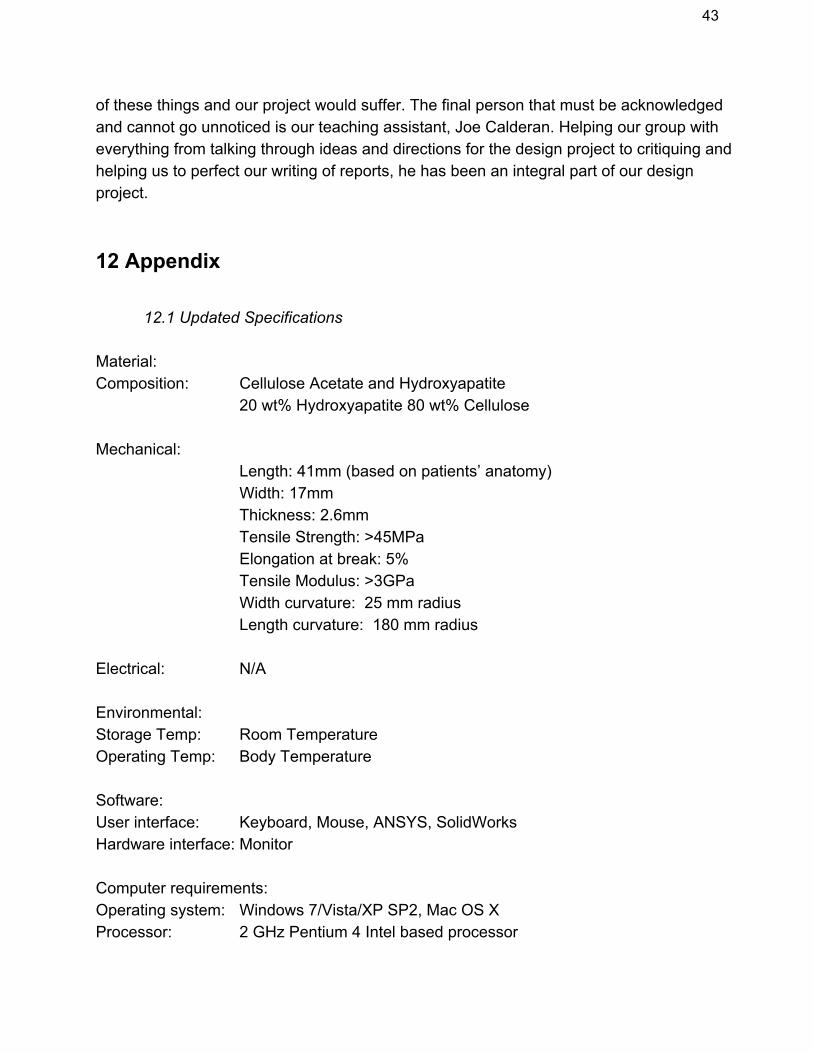
43
of these things and our project would suffer. The final person that must be acknowledgedand cannot go unnoticed is our teaching assistant, Joe Calderan. Helping our group witheverything from talking through ideas and directions for the design project to critiquing andhelping us to perfect our writing of reports, he has been an integral part of our designproject.
12 Appendix
12.1 Updated Specifications
Material:Composition: Cellulose Acetate and Hydroxyapatite
20 wt% Hydroxyapatite 80 wt% Cellulose
Mechanical:Length: 41mm (based on patients’ anatomy)Width: 17mmThickness: 2.6mmTensile Strength: >45MPaElongation at break: 5%Tensile Modulus: >3GPaWidth curvature: 25 mm radiusLength curvature: 180 mm radius
Electrical: N/A
Environmental:Storage Temp: Room TemperatureOperating Temp: Body Temperature
Software:User interface: Keyboard, Mouse, ANSYS, SolidWorksHardware interface: Monitor
Computer requirements:Operating system: Windows 7/Vista/XP SP2, Mac OS XProcessor: 2 GHz Pentium 4 Intel based processor

44
Memory: 1 GHz
Safety: N/A
Maintenance: Sterilization