Embed Size (px)
Citation preview
ELEKTRONIKA IR ELEKTROTECHNIKA, ISSN 1392-1215, VOL. 22, NO. 1, 2016
1Abstract—A realized frequency and amplitude controlledpower converter for driving electromagnetic vibratory feedersis presented. By using a microcontroller-based control systemdesigned for the converter, it was possible to accomplishcontinuous variation of the frequency and amplitude ofvibrations, perform search of the resonant frequency of themechanical vibratory system, and maintain the system in thestate of resonance. Operation in the resonance mode isconvenient since consumption of the system is kept at minimum.Finally, the corresponding experimental results are presented.
Index Terms—Control, frequency, microprocessor,switching converter, vibration.
I. INTRODUCTION
Vibratory movement is one of the most efficient methodsof conveyance of granular and particulate materials.Vibratory conveyors are widely applied in manytechnological processes involving gravimetric transport,processing, and dosing of granular materials. From themacroscopic point of view, the process of vibratoryconveyance is based on recurrent micro-throws of particlesof the material being conveyed [1]–[4]. Classical solutionsfor power converters used in industrial systems for feedingand transportation of granular materials are based onthyristors or triacs [5], [6]. These solutions have shown veryflexible and reliable in industry, but they implied a fixedfrequency of vibrations. By applying phase control, one canaccomplish amplitude control (vibration width), while thefrequency of vibrations is dictated by the power distributionnetwork (50 Hz/60 Hz) [5], [7]. With these converters,depending on the control method, it is possible toaccomplish frequencies 25 Hz/30 Hz or 100 Hz/120 Hz.Even though these frequencies meet the requirements fortransportation of majority of granular materials, in sometechnological processes a continuously variable frequency ofvibrations is required. One of the deficiencies of the phasecontrolled converters is generation of detrimental harmonicsin the power network thereby causing deterioration of thepower factor. This is particularly pronounced when a largenumber of transporters operate in a system for feeding
Manuscript received 3 April, 2015; accepted 21 December, 2015.This research was funded by a grant No. TR33022 founded by Ministry
of Education, Science an Technological Development of Republic Serbia.
and/or transportation of granular materials [3]. Applicationof modern flexible automatic systems implies that thefeeding units have to fulfill specific requirements. Thisprimarily concerns the output power converter which has tobe capable of driving different types of electromagneticvibrators. A considerable problem is the influence ofvariations of parameters of the system. Variation of the massof the material in the compartment for transportation, or forfeeding, changes the resonant frequency of the system. Also,a change of resonant frequency occurs with variation ofcharacteristics of the springs due to ageing, since they areexposed to very large dynamic stresses. Owing to theseinfluences, any vibration system will not operate with itsoptimum efficiency. Since a conventional thyristor converteroperates at 50 Hz or 100 Hz, the vibration mechanism has tobe readjusted. This is accomplished by varying the system ofsprings or by balancing masses with the use of thecorresponding tools. For feeder applications in countrieshaving power distribution network frequency 60 Hz, thevibratory system has to be adjusted to this frequency, i.e. tofrequencies 60 Hz/120 Hz in order to accomplishoscillations of 3600/7200 cycles/min. This includes doublingthe mechanical components.
II. FREQUENCY CONTROLLED VIBRATORY FEEDERS
The basis of these systems consists of the power converterand the associated control/regulation electronic circuitrywhich serves for: adjusting the power taken by the vibratoryfeeder from the network, making continuous search for, andmonitoring, the mechanical resonance frequency of thesystem. A power converter consists of the input rectifier,containing a built-in intermediate DC filtering circuit, andthe output transistor stage [7]–[9]. It could also contain apower factor corrector. Then, instead of an input dioderectifier, a transistor rectifier, consisting of two transistors,two diodes, and a choke on the AC side, is used. One suchconverter performing power factor correction, havingadvantages over the conventional “boost” power factorcorrector (diode rectifier, switch, diode, and choke in the DCintermediate circuit), is described in [10] and [11].
One of the methods of obtaining sinusoidal form ofcurrent of vibrator’s electromagnet is the use of transistorconverters having programmed current control. If a
Optimization of the Operation and FrequencyControl of Electromagnetic Vibratory Feeders
Vladimir Sinik1, Zeljko Despotovic2, Ivan Palinkas1
1University of Novi Sad, Technical faculty “Mihajlo Pupin”,Djure Djakovica BB, 23000 Zrenjanin, Serbia
2University of Belgrade, Institute “Mihajlo Pupin”,Volgina 15, 11000 Belgrade, Serbia
http://dx.doi.org/10.5755/j01.eee.22.1.14095
24
ELEKTRONIKA IR ELEKTROTECHNIKA, ISSN 1392-1215, VOL. 22, NO. 1, 2016
bidirectional control is to be accomplished, the outputconverter can be realized as a bridge configuration (full-bridge), whereas for unidirectional control a half-bridgeconfiguration is used. The output converter generatessinusoidal current wave for the case of a full-bridgeconfiguration, or a sinusoidal current half-wave for the caseof a half-bridge configuration. Frequency of the sinusoidalwave is adjustable within the range from 10 Hz to 150 Hz, itis independent of the network frequency, and serves fordriving vibrator’s electromagnet.
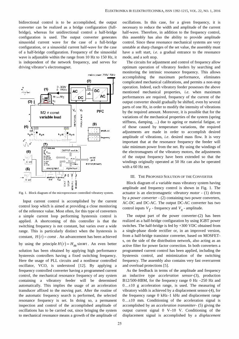
Fig. 1. Block diagram of the microprocessor controlled vibratory system.
Input current control is accomplished by the currentcontrol loop which is aimed at providing a close monitoringof the reference value. Most often, for this type of convertersa simple current loop performing hysteresis control isapplied. A shortcoming of this controller is that theswitching frequency is not constant, but varies over a widerange. This is particularly distinct when the hysteresis isconstant, H t const . An advancement has been achieved
by using the principle sinH t H tm . An even better
solution has been obtained by applying high performancehysteresis controllers having a fixed switching frequency.Here the usage of PLL circuits and a nonlinear controlledoscillator, VCO, is understood [12]. By applying afrequency controlled converter having a programmed currentcontrol, the mechanical resonance frequency of any systemcontaining a vibratory feeder will be determinedautomatically. This implies the usage of an accelerationtransducer affixed to the moving part. After the routine ofthe automatic frequency search is performed, the selectedresonance frequency is set. In doing so, a permanentinspection and control of the accomplished amplitude ofoscillations has to be carried out, since bringing the systemto mechanical resonance means a growth of the amplitude of
oscillations. In this case, for a given frequency, it isnecessary to reduce the width and amplitude of the currenthalf-wave. Therefore, in addition to the frequency control,this assembly has also the ability to provide amplitudecontrol. Since these resonance mechanical systems are veryunstable at sharp changes of the set value, the assembly musthave a soft start, i.e. a gradual entrance to the resonancemode, and a soft stop.
The circuits for adjustment and control of frequency allowoptimum operation of vibratory feeders by searching andmonitoring the intrinsic resonance frequency. This allowsaccomplishing the maximum performance, eliminatescomplicated mechanical calibrations, and permits a non-stopoperation. Indeed, each vibratory feeder possesses the abovementioned mechanical properties, i.e. when maximumperformances are required, frequency of the current of theoutput converter should gradually be shifted, even by severalparts of one Hz, in order to modify the intensity of vibrationsby the required amount. Moreover, it is possible that for thevariations of the mechanical properties of the system (springstiffness, damping, ...) due to ageing or material fatigue, orof those caused by temperature variations, the requiredadjustments are made in order to accomplish desiredamplitude of vibrations, i.e. desired mass flow. It is veryimportant that at the resonance frequency the feeder willtake minimum power from the net. By using the windings ofthe electromagnets of the vibratory motors, the adjustmentsof the output frequency have been extended so that thewindings originally operated at 50 Hz can also be operatedwith a 60 Hz net.
III. THE PROPOSED SOLUTION OF THE CONVERTER
Block diagram of a variable mass vibratory system havingamplitude and frequency control is shown in Fig. 1. Theactuator is an electromagnetic vibratory motor - (1) drivenby a power converter - (2) containing two power converters,AC-DC and DC-AC. The output DC-AC converter has twocontrol inputs V f - frequency and Vx - amplitude.
The output part of the power converter-(2) has beenrealized as a half-bridge configuration by using IGBT powerswitches. The half-bridge is fed by +300 VDC obtained froma single-phase diode rectifier or, in an improved version,from a half-bridge transistor converter, based on MOSFET-s, on the side of the distribution network, also acting as anactive filter for power factor correction. In both converters aprogrammed current control has been applied, including thehysteresis control, and minimization of the switchingfrequency. The assembly also contains very fast overcurrentand overload protections [5].
As the feedback in terms of the amplitude and frequencyan inductive type acceleration sensor-(3), productionB12/500-HBM, for the frequency range 0 Hz –250 Hz and0…±10 g acceleration range, is used. The measuring ofvibratory width is achieved by a displacement sensor-(4), forthe frequency range 0 kHz–1 kHz and displacement range0…±10 mm. Conditioning of the acceleration signal isaccomplished by an acceleration transmitter- (5) giving theoutput current signal 0 V–10 V. Conditioning of thedisplacement signal is accomplished by a displacement
25
ELEKTRONIKA IR ELEKTROTECHNIKA, ISSN 1392-1215, VOL. 22, NO. 1, 2016
transmitter-(6) giving the output signal 0 kHz–10 V. Bothsignals are connected to the printed circuit board containinganalogue inputs of the controller assembly.
Setting the reference current values is performed by aseparate assembly operating at a stable frequency (over therange 0 Hz–200 Hz) and amplitude (0 V–10 V), which alsocontains the soft-start and soft-stop circuits havingadjustable times of starting and stopping the drive. Theconverter may produce output currents up to 40 A and iscapable of driving high power mechanical resonance systems(up to several tens of kW).
The microprocessor assembly-(7) serving for control ofthe converter is based on microcontroller 80C537-SIEMENS and it consists of several modules: CPU, I/O,keyboard for setting values, display, and LED indicators forstatus presentation. Setting the amplitude and frequency ofvibrations is accomplished by externally addedpotentiometers or by the keyboard if in manual mode ordirectly by the microcontroller in automatic mode. Inaddition to this function, a series of other functions is alsorealized, such as maintenance of amplitude, searching forresonance frequency, supervision, and control. The assemblycontains also an RS232 (RS485) interface, a voltage output0 V–10 V, and a current output 4 mA–20 mA.
The output module consists of two serial D/A converterswhere the microprocessor enters (writes-in serially) thedesired values of the frequency and amplitude. The serialwriting implies a synchronous one-sided serial access whenthe microcontroller generates the clock signal, data signal forD/A converter, as well as the write-in signal to the buffer ofD/A converter. The two mentioned D/A converters are 12bit, with the output voltage from 0 V to 4.25 V. Thedisplays-(8) showing values of the amplitude and frequencyof vibrations entered by the microcontroller, are standard 4-digit, 7-segment LED’s, adjusted to industrial applications.The displays are of serial types and contain displaycontrollers. The desired data are written-in serially by themicroprocessor. The connection is one-sided of synchronoustype: CLOCK+DATA+ WRITE IN SIGNAL.
IV. DETERMINATION OF THE RESONANCE FREQUENCY OFTHE SYSTEM
At the start it is necessary to determine the resonancefrequency of the system. There are two acceptable methodsof determination of the resonance frequency. These are “on-line” search and analysis in the frequency domain. Thefrequency analysis implies obtaining frequency response ofthe system to a step-up Heaviside function. The appliedmicrocontroller, unfortunately, is not sufficiently fast for thistype of signal processing which requires the application ofthe modern DSP methods.
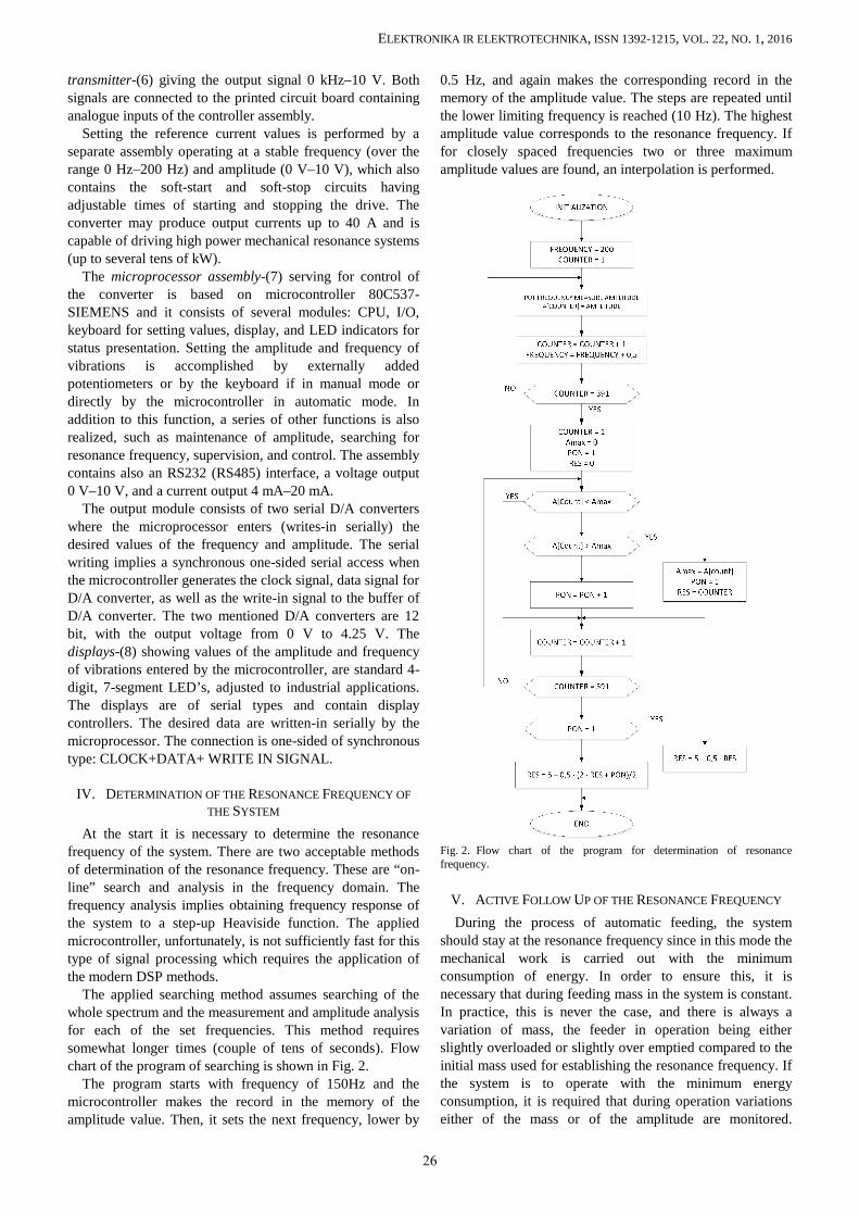
The applied searching method assumes searching of thewhole spectrum and the measurement and amplitude analysisfor each of the set frequencies. This method requiressomewhat longer times (couple of tens of seconds). Flowchart of the program of searching is shown in Fig. 2.
The program starts with frequency of 150Hz and themicrocontroller makes the record in the memory of theamplitude value. Then, it sets the next frequency, lower by
0.5 Hz, and again makes the corresponding record in thememory of the amplitude value. The steps are repeated untilthe lower limiting frequency is reached (10 Hz). The highestamplitude value corresponds to the resonance frequency. Iffor closely spaced frequencies two or three maximumamplitude values are found, an interpolation is performed.
Fig. 2. Flow chart of the program for determination of resonancefrequency.
V. ACTIVE FOLLOW UP OF THE RESONANCE FREQUENCY
During the process of automatic feeding, the systemshould stay at the resonance frequency since in this mode themechanical work is carried out with the minimumconsumption of energy. In order to ensure this, it isnecessary that during feeding mass in the system is constant.In practice, this is never the case, and there is always avariation of mass, the feeder in operation being eitherslightly overloaded or slightly over emptied compared to theinitial mass used for establishing the resonance frequency. Ifthe system is to operate with the minimum energyconsumption, it is required that during operation variationseither of the mass or of the amplitude are monitored.
26
ELEKTRONIKA IR ELEKTROTECHNIKA, ISSN 1392-1215, VOL. 22, NO. 1, 2016
Amplitudes outside the resonance will always be smallerthan in the resonance.
At standard operating mode, 3 s after the controller isturned on, there follows a search for the resonance frequencywithin the range from 150 Hz to 10 Hz.
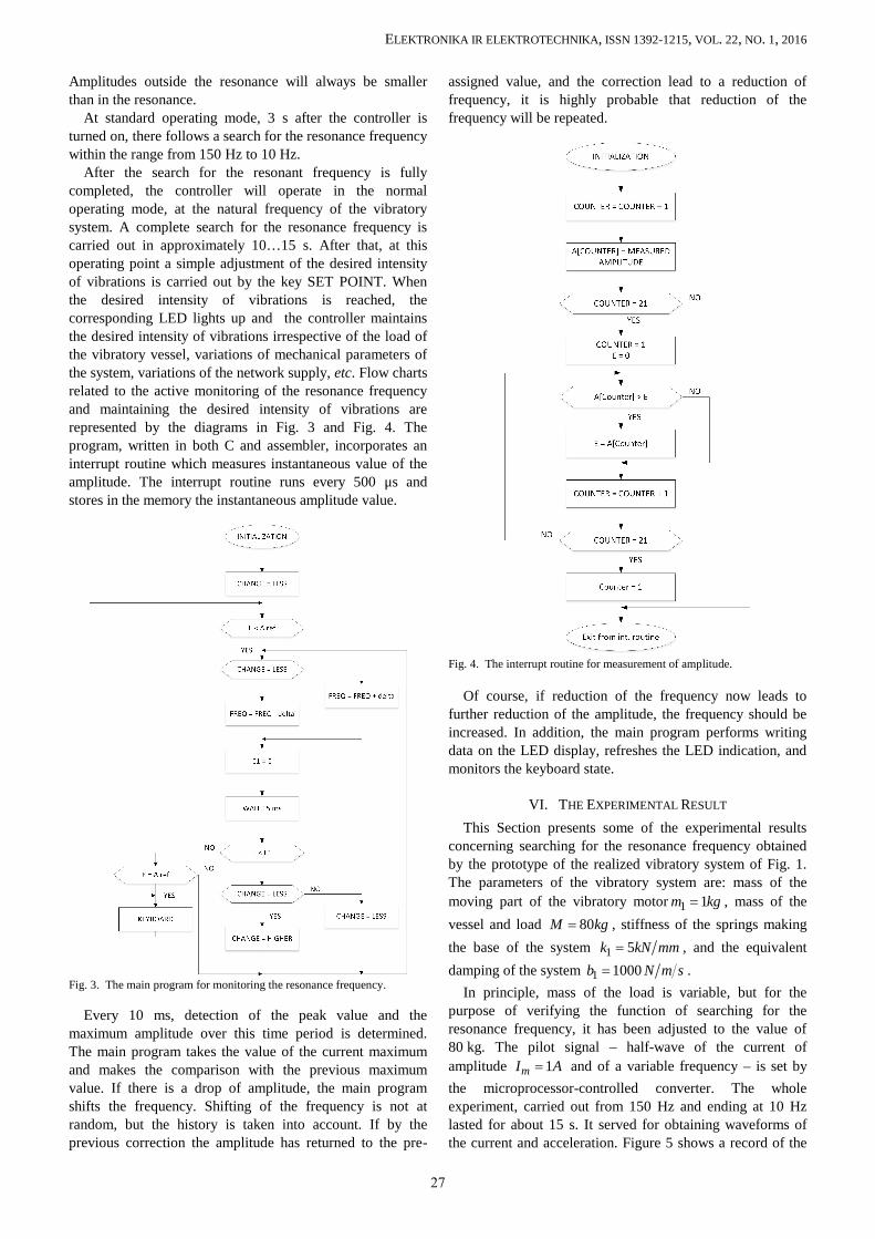
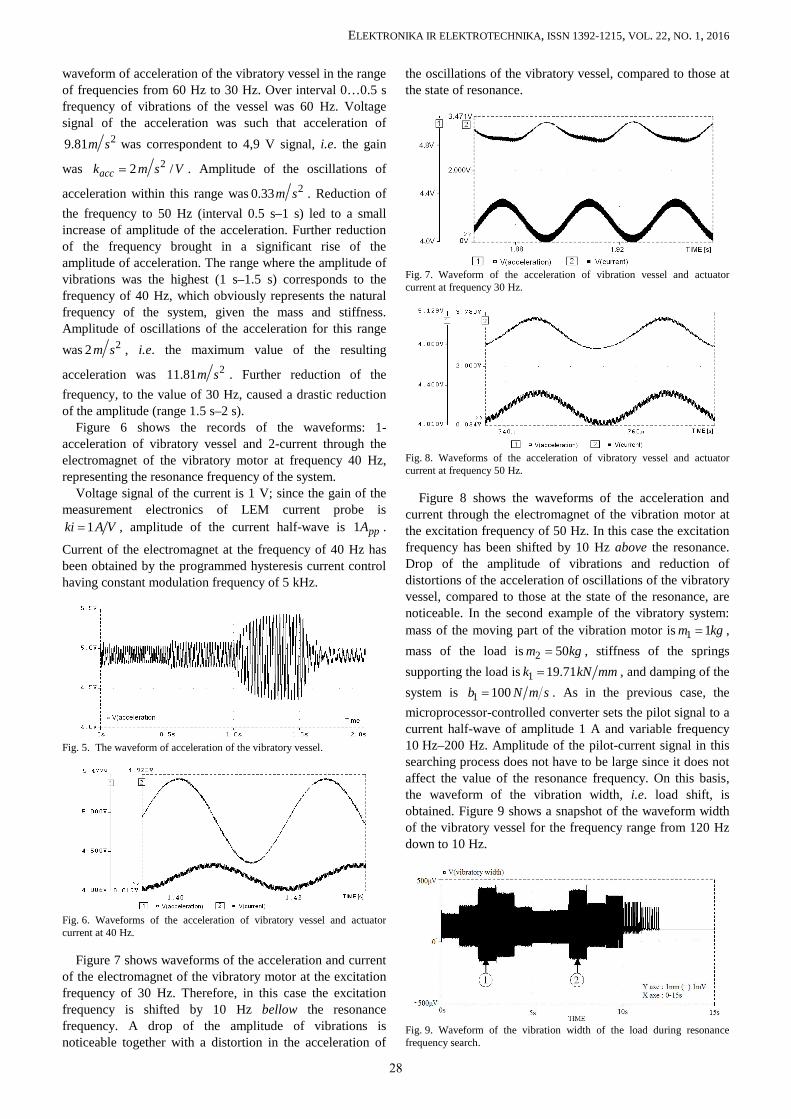
After the search for the resonant frequency is fullycompleted, the controller will operate in the normaloperating mode, at the natural frequency of the vibratorysystem. A complete search for the resonance frequency iscarried out in approximately 10…15 s. After that, at thisoperating point a simple adjustment of the desired intensityof vibrations is carried out by the key SET POINT. Whenthe desired intensity of vibrations is reached, thecorresponding LED lights up and the controller maintainsthe desired intensity of vibrations irrespective of the load ofthe vibratory vessel, variations of mechanical parameters ofthe system, variations of the network supply, etc. Flow chartsrelated to the active monitoring of the resonance frequencyand maintaining the desired intensity of vibrations arerepresented by the diagrams in Fig. 3 and Fig. 4. Theprogram, written in both C and assembler, incorporates aninterrupt routine which measures instantaneous value of theamplitude. The interrupt routine runs every 500 μs andstores in the memory the instantaneous amplitude value.
Fig. 3. The main program for monitoring the resonance frequency.
Every 10 ms, detection of the peak value and themaximum amplitude over this time period is determined.The main program takes the value of the current maximumand makes the comparison with the previous maximumvalue. If there is a drop of amplitude, the main programshifts the frequency. Shifting of the frequency is not atrandom, but the history is taken into account. If by theprevious correction the amplitude has returned to the pre-
assigned value, and the correction lead to a reduction offrequency, it is highly probable that reduction of thefrequency will be repeated.
Fig. 4. The interrupt routine for measurement of amplitude.
Of course, if reduction of the frequency now leads tofurther reduction of the amplitude, the frequency should beincreased. In addition, the main program performs writingdata on the LED display, refreshes the LED indication, andmonitors the keyboard state.
VI. THE EXPERIMENTAL RESULT
This Section presents some of the experimental resultsconcerning searching for the resonance frequency obtainedby the prototype of the realized vibratory system of Fig. 1.The parameters of the vibratory system are: mass of themoving part of the vibratory motor 1 1m kg , mass of thevessel and load 80M kg , stiffness of the springs makingthe base of the system 1 5k kN mm , and the equivalentdamping of the system 1 1000b N m s .
In principle, mass of the load is variable, but for thepurpose of verifying the function of searching for theresonance frequency, it has been adjusted to the value of80 kg. The pilot signal – half-wave of the current ofamplitude 1mI A and of a variable frequency – is set bythe microprocessor-controlled converter. The wholeexperiment, carried out from 150 Hz and ending at 10 Hzlasted for about 15 s. It served for obtaining waveforms ofthe current and acceleration. Figure 5 shows a record of the
27
ELEKTRONIKA IR ELEKTROTECHNIKA, ISSN 1392-1215, VOL. 22, NO. 1, 2016
waveform of acceleration of the vibratory vessel in the rangeof frequencies from 60 Hz to 30 Hz. Over interval 0…0.5 sfrequency of vibrations of the vessel was 60 Hz. Voltagesignal of the acceleration was such that acceleration of
29.81m s was correspondent to 4,9 V signal, i.e. the gain
was 22 /acck m s V . Amplitude of the oscillations of
acceleration within this range was 20.33m s . Reduction ofthe frequency to 50 Hz (interval 0.5 s–1 s) led to a smallincrease of amplitude of the acceleration. Further reductionof the frequency brought in a significant rise of theamplitude of acceleration. The range where the amplitude ofvibrations was the highest (1 s–1.5 s) corresponds to thefrequency of 40 Hz, which obviously represents the naturalfrequency of the system, given the mass and stiffness.Amplitude of oscillations of the acceleration for this rangewas 22m s , i.e. the maximum value of the resulting
acceleration was 211.81m s . Further reduction of thefrequency, to the value of 30 Hz, caused a drastic reductionof the amplitude (range 1.5 s–2 s).
Figure 6 shows the records of the waveforms: 1-acceleration of vibratory vessel and 2-current through theelectromagnet of the vibratory motor at frequency 40 Hz,representing the resonance frequency of the system.
Voltage signal of the current is 1 V; since the gain of themeasurement electronics of LEM current probe is
1ki A V , amplitude of the current half-wave is 1 ppA .
Current of the electromagnet at the frequency of 40 Hz hasbeen obtained by the programmed hysteresis current controlhaving constant modulation frequency of 5 kHz.
Fig. 5. The waveform of acceleration of the vibratory vessel.
Fig. 6. Waveforms of the acceleration of vibratory vessel and actuatorcurrent at 40 Hz.
Figure 7 shows waveforms of the acceleration and currentof the electromagnet of the vibratory motor at the excitationfrequency of 30 Hz. Therefore, in this case the excitationfrequency is shifted by 10 Hz bellow the resonancefrequency. A drop of the amplitude of vibrations isnoticeable together with a distortion in the acceleration of
the oscillations of the vibratory vessel, compared to those atthe state of resonance.
Fig. 7. Waveform of the acceleration of vibration vessel and actuatorcurrent at frequency 30 Hz.
Fig. 8. Waveforms of the acceleration of vibratory vessel and actuatorcurrent at frequency 50 Hz.
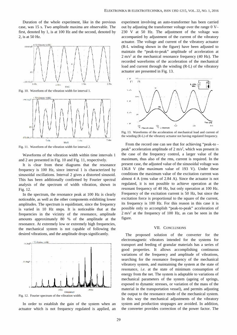
Figure 8 shows the waveforms of the acceleration andcurrent through the electromagnet of the vibration motor atthe excitation frequency of 50 Hz. In this case the excitationfrequency has been shifted by 10 Hz above the resonance.Drop of the amplitude of vibrations and reduction ofdistortions of the acceleration of oscillations of the vibratoryvessel, compared to those at the state of the resonance, arenoticeable. In the second example of the vibratory system:mass of the moving part of the vibration motor is 1 1m kg ,mass of the load is 2 50m kg , stiffness of the springssupporting the load is 1 19.71k kN mm , and damping of thesystem is 1 100b N m s . As in the previous case, themicroprocessor-controlled converter sets the pilot signal to acurrent half-wave of amplitude 1 A and variable frequency10 Hz–200 Hz. Amplitude of the pilot-current signal in thissearching process does not have to be large since it does notaffect the value of the resonance frequency. On this basis,the waveform of the vibration width, i.e. load shift, isobtained. Figure 9 shows a snapshot of the waveform widthof the vibratory vessel for the frequency range from 120 Hzdown to 10 Hz.
Fig. 9. Waveform of the vibration width of the load during resonancefrequency search.
28
ELEKTRONIKA IR ELEKTROTECHNIKA, ISSN 1392-1215, VOL. 22, NO. 1, 2016
Duration of the whole experiment, like in the previouscase, was 15 s. Two amplitude maxima are observable. Thefirst, denoted by 1, is at 100 Hz and the second, denoted by2, is at 50 Hz.
Fig. 10. Waveform of the vibration width for interval 1.
Fig. 11. Waveform of the vibration width for interval 2.
Waveforms of the vibration width within time intervals 1and 2 are presented in Fig. 10 and Fig. 11, respectively.
It is clear from these diagrams that the resonancefrequency is 100 Hz, since interval 1 is characterized bysinusoidal oscillations. Interval 2 gives a distorted sinusoid.This has been additionally confirmed by Fourier spectralanalysis of the spectrum of width vibration, shown inFig. 12.
In the spectrum, the resonance peak at 100 Hz is clearlynoticeable, as well as the other components exhibiting loweramplitudes. The spectrum is equidistant, since the frequencyis varied in 10 Hz steps. It is noticeable that at thefrequencies in the vicinity of the resonance, amplitudeamounts approximately 80 % of the amplitude at theresonance. At extremely low or extremely high frequencies,the mechanical system is not capable of following thedesired vibrations, and the amplitude drops significantly.
Fig. 12. Fourier spectrum of the vibration width.
In order to establish the gain of the system when anactuator which is not frequency regulated is applied, an
experiment involving an auto-transformer has been carriedout by adjusting the transformer voltage over the range 0 V–230 V at 50 Hz. The adjustment of the voltage wasaccompanied by adjustment of the current of the vibratoryactuator. The voltage and current of the vibratory actuator(R-L winding shown in the figure) have been adjusted tomaintain the “peak-to-peak” amplitude of acceleration at2 m/s2 at the mechanical resonance frequency (40 Hz). Therecorded waveforms of the acceleration of the mechanicalload and current through the winding (R-L) of the vibratoryactuator are presented in Fig. 13.
Fig. 13. Waveforms of the acceleration of mechanical load and current ofthe winding (R-L) of the vibratory actuator not having regulated frequency.
From the record one can see that for achieving “peak-to -peak” acceleration amplitude of 2 m/s2, which was present inthe case of the frequency control, a larger value of themaximum, thus also of the rms, current is required. In thepresent case, the adjusted value of the sinusoidal voltage was136.8 V (the maximum value of 193 V). Under theseconditions the maximum value of the excitation current wasalmost 4 A (rms value of 2.84 A). Since the actuator is notregulated, it is not possible to achieve operation at theresonant frequency of 40 Hz, but only operation at 100 Hz.Frequency of the excitation current is 50 Hz, but since theexcitation force is proportional to the square of the current,its frequency is 100 Hz. For this reason in this case it ispossible only to accomplish “peak-to-peak” acceleration of2 m/s2 at the frequency of 100 Hz, as can be seen in thefigure.
VII. CONCLUSIONS
The proposed solution of the converter for theelectromagnetic vibrators intended for the systems fortransport and feeding of granular materials has a series ofgood properties. It allows accomplishing continuousvariations of the frequency and amplitude of vibrations,searching for the resonance frequency of the mechanicalvibratory system, and maintaining the system at the state ofresonance, i.e. at the state of minimum consumption ofenergy from the net. The system is adaptable to variations ofmechanical parameters of the system (ageing of springs,exposed to dynamic stresses, or variation of the mass of thematerial in the transportation vessel), and permits adjustingthe output to the resonance mode of the mechanical system.In this way the mechanical adjustments of the vibratorysystem and production stoppages are avoided. In addition,the converter provides correction of the power factor. The
29
ELEKTRONIKA IR ELEKTROTECHNIKA, ISSN 1392-1215, VOL. 22, NO. 1, 2016
converter can be applied in distribution networksirrespective of the network frequency (50 Hz or 60 Hz).
The idea for development of this converter originatedfrom the experience acquired from realization of thethyristor- or triac-based converters and evaluation of theirdeficiencies while they were applied in the system forfeeding of clinker in the Factory of cement “Novi Popovac”in Serbia. The converter could also be applied in otherindustrial processes which include transportation of granularmaterials (pharmaceutical, foods, civil engineering materials,etc.).
REFERENCES
[1] E. M. Sloot, N. P. Kruyt, “Theoretical and experimental study of theconveyance of granular materials by inclined vibratory conveyors”,Powder Technology, vol. 87, no. 3, pp. 203–210, 1996. [Online].Available: http://dx.doi.org/10.1016/0032-5910(96)03091-4
[2] G. Rein, A. Andrés, “Computer simulation of granular material:vibrating feeders”, Powder Handling and Processing, vol. 13, no. 2,2001.
[3] I. F. Goncharevich, K. V. Frolov, E. I. Rivin, Theory of vibratorytechnology. Hemisphere Publishing Corporation: New York, 1990.
[4] T. Dyr, P. Wodzinski, “Model particle velocity on a vibratingsurface”, Physicochemical Problems of Mineral Processing, vol. 36,pp. 147–157, 2002.
[5] Z. Despotovic, Z. Stojiljkovic, “Power converter control circuits fortwo-mass vibratory conveying system with electromagnetic drive:
simulations and experimental results”, IEEE Trans. IndustrialElectronics, vol. 54, no. 1, pp. 453–466, 2007. [Online]. Available:http://dx.doi.org/10.1109/TIE.2006.888798
[6] Z. Despotovic, Z. Stojiljkovic, “PSPICE simulation of two massvibratory conveying system with electromagnetic drive”, in Proc. ofInt. Conf. “Computer as a tool”, Belgrade, 2005, pp.1509–1512.[Online]. Available: http://dx.doi.org/10.1109/eurcon.2005.1630251
[7] Z. V. Despotovic, A. I. Ribic, V. Sinik, “Power current control of aresonant vibratory conveyor having electromagnetic drive”, Journalof Power Electronics, vol. 12, no. 4, 2012. [Online]. Available:http://dx.doi.org/10.6113/JPE.2012.12.4.677
[8] A. I. Ribic, Z. Despotovic, “High-performance feedback control ofelectromagnetic vibratory feeder”, IEEE Trans. IndustrialElectronics, vol. 57, no. 9, 2010, pp. 3087–3094. [Online]. Available:http://dx.doi.org/10.1109/TIE.2009.2037677
[9] I. J. Sokolov, V. I. Babitsky, N. A. Halliwell, “Autoresonant vibro-impact system with electromagnetic excitation”, Journal of Soundand Vibration, no. 308, pp. 375–391, 2007. [Online]. Available:http://dx.doi.org/10.1016/j.jsv.2007.04.010
[10] R. Martinez, P. N. Enjeti, “A high performance single phase rectifierwith input power factor correction”, IEEE Trans. Power Electron.,vol. 11, no. 2, pp. 311–317, 1996. [Online]. Available:http://dx.doi.org/10.1109/63.486181
[11] A. Ferrari de Souza, I. Barbi, “A New ZVS-PWM unity power factorrectifier with reduced conduction losses”, IEEE Trans. PowerElectron., vol. 10, no. 6, pp. 746–752, 1996. [Online]. Available:http://dx.doi.org/10.1109/63.471294
[12] L. Malesani, P. Mattavelli, P. Tomasin, “High-performance hysteresismodulation technique for active filters”, IEEE Trans. PowerElectron., vol. 12, no. 5, pp. 876–884, 1996.[Online]. Available:http://dx.doi.org/10.1109/63.623006
30