Embed Size (px)
Citation preview

F.Maviglia 1 (27) 7th Workshop on Fusion Data Processing Validation and Analysis. Frascati 26 - 28 March 2012
Optimization of the magnetic field Optimization of the magnetic field configuration for JET breakdownconfiguration for JET breakdown
F. MavigliaF. Maviglia
with contribution from
R. Albanese, P.J. R. Albanese, P.J. LomasLomas, A. , A. ManzanaresManzanares, M. , M. MatteiMattei, A. , A. NetoNeto, F.G. , F.G. RiminiRimini, P.C. de , P.C. de VriesVries
and JET EFDA Contributorsand JET EFDA Contributors
F.Maviglia 2 (27) 7th Workshop on Fusion Data Processing Validation and Analysis. Frascati 26 - 28 March 2012
Introduction
Modelling activity
Static and dynamic simulations
Intensified Visible Fast Camera KL8A
Experimental results
Conclusions
OutlineOutline

F.Maviglia 3 (27) 7th Workshop on Fusion Data Processing Validation and Analysis. Frascati 26 - 28 March 2012
filling pressure;
toroidal electric field (E0
≈1V/m in present Tokamaks, E0
≈0.33V/m ITER);
magnetic field configuration (null position and extension of the low field region);
Breakdown optimization parameters:
1 2 3 4 5 6
−4
−3
−2
−1
0
1
2
3
4
ΔΨ = 0.01 Vs
R (m)
Z (m
)
IPRIM −15 (kA)IP4T 180 (A) IERFA 0(A)
1
2
3
4
5
6 7
8 9 10 11 12 13
14
15
16
17
18
P3ML
P3MU
P1
P2RU
P2RL
P3RU
P3RL
P4U
P4L
Static simulation
IPRIM transformer (open loop):• mode D,C initial value(=premag)[-7,-40] kA, iron fully saturated;• mode B premag ≈
0, iron with residual magnetization;
IP4 Vertical field (open loop)IERFA radial field (feedback)
Circuits used for breakdown at JET:
IntroductionIntroduction
Hexapolar field

F.Maviglia 4 (27) 7th Workshop on Fusion Data Processing Validation and Analysis. Frascati 26 - 28 March 2012
IntroductionIntroduction
;41
z
nullc B
BaL
z
null
BBa
= size of the field min.
P = pressure;
E = electric field;
= avg. stray field over the null;
;103.1exp102 43
EP
Pi
Avalanche
successful
if
Lc
/λi
>> 1minimize
<δBz
>, maximize
anull
•Connection length Lc
[1]:
•Ionization length
λi
:
= toroidal field;
1 2 3 4 5
−3
−2
−1
0
1
2
3
R [m]
Z [m
] ΔΨ = 0.01 Vs iso B= [0.5;1;1.5;2;2.5] mT
IP1 −15 [kA]IP4 180 [A]
with:
with:
Magnetic field configuration
[1] B. LLoyd, et al., Nucl. Fus. 31 (1991) 2031.
F.Maviglia 5 (27) 7th Workshop on Fusion Data Processing Validation and Analysis. Frascati 26 - 28 March 2012
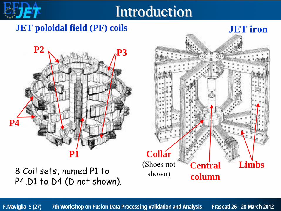
JET poloidal field (PF) coils JET iron
8 Coil sets, named P1 to P4,D1 to D4 (D not shown).
P4
P3
LimbsP1
P2
Central column
Collar(Shoes not
shown)
IntroductionIntroduction

F.Maviglia 6 (27) 7th Workshop on Fusion Data Processing Validation and Analysis. Frascati 26 - 28 March 2012
•CREATE Model [1] based on 2D FEM:•Passive structures: MS, VV, RR, MK2. Resistivity value of MS has been refined via best fit of the simulations with the experimental data. Resistivity of VV, RR, MK2 in agreement with [2-3].
References:[1] R. Albanese et
al., Nucl. Fusion, 38, 1998, pp. 723–738.[2] R. Albanese, et.al. Nucl. Fusion 44 (2004) 999–1007.[3] S.Gerasimov, ‘
JET_PassiveSimpleModel.pdf ‘.
Passive structures
#78021 (Ipre = -15kA)
Dyn. Sim. v.s. exp. estimations of mk2 current
ModellingModelling

F.Maviglia 7 (27) 7th Workshop on Fusion Data Processing Validation and Analysis. Frascati 26 - 28 March 2012
0 2 4 6−6
−4
−2
0
2
4
6
CREATE−NL/CREATE−L model
R [m]Z
[m
]
JET Iron Model
Centre limb pad
Outer limb pad3 mm gap present in the magnetic circuit at z=4.5m, and not at z=-4.5m, present at JET and considered in the model: up-down asymmetry.
-Outer limb pad: thickness 3mm
-Centre limb pad: thickness 3mm
CREATE iron model
ModellingModelling

F.Maviglia 8 (27) 7th Workshop on Fusion Data Processing Validation and Analysis. Frascati 26 - 28 March 2012
E
Mode D breakdownStatic simulation using as input primary and vertical field current (other noisy curr. set to 0).
-Hexapole null splits in two quadrupole nulls in the direction of the radial field given by the upper iron gaps.
-Inboard-low null expected to be preferred for plasma formation for the higher electrical field.
|Br|≈0.35mT
Critical points for JET breakdown magnetic reconstruction: Residual iron magnetization, not included in present exp. measurements; Perturbing effect of vessel and in-vessel passive currents.
StaticStatic simulationssimulations

F.Maviglia 9 (27) 7th Workshop on Fusion Data Processing Validation and Analysis. Frascati 26 - 28 March 2012
Configurations used for breakdown:Configuration 1 Configuration 2 Improved
2 2.5 3 3.5
−1.5
−1
−0.5
0
0.5
1
1.5
2
R [m]
Z [m
]
Z [m
]
IntensifiedIntensified
VisibleVisible
Fast Camera KL8AFast Camera KL8A
Specifications
Region of interest
272 x 384 px
Freq. 1.0 kHz
Exposur e Time
142.9 s
Filter none
Intensifi er Gain 700 v
Specifications
Region of interest
176 x 256 px
Freq. 7.5 kHz
Exposur e Time
125.0 s
Filter none
Intensifi er Gain 750 v

F.Maviglia 10 (27) 7th Workshop on Fusion Data Processing Validation and Analysis. Frascati 26 - 28 March 2012
Comparison between dynamic simulation
and fast camera [1] (carbon wall):-Inner field null preferred for plasma formation.-Plasma pushed against the inboard and included in the region between the two lines where Btg
= 0. -The ionization cloud appears to be pushed down in the divertor region. -For a successful breakdown the plasma is pushed up toward the outer wall.
-0.5
0
0.5
1.0
1.5
2.0
Pulse No: 78369t = 0.006028s
Pulse No: 78369CREATE L flux-map
2.5
-1.0
-1.5
-2.0
-2.5 2.01.5 2.5 3.0 3.5 4.0 4.5
Z (m
)
IPRIM = -19.4(kA)IP4T = 123(A)IFRFA = 138(A)Other 0(A)
6ms
Force
Δψ = 0.02Vs
R (m)
JG10
.248
-4c
1.5
2.0
1.0
0.5
0
-0.5
-1.0
-1.5
2.52.0 3.0 3.5
Z (m
)
R (m)
1.5
2.0
1.0
0.5
0
-0.5
-1.0
-1.5
2.52.0 3.0 3.5
Z (m
)
R (m)
1.5
2.0
1.0
0.5
0
-0.5
-1.0
-1.5
2.52.0 3.0 3.5
Z (m
)
R (m)
JG10
.248
-5c
Pulse No: 78369t = 0.014028s
Pulse No: 78369t = 0.028028s
Pulse No: 78369t = 0.038028s
time increasing
[1] F.Mavilgia et al.,Fus. Eng. and Des. 86 (2011) 675–679.
Standard non optimized breakdown dynamic evolution
H
L

F.Maviglia 11 (27) 7th Workshop on Fusion Data Processing Validation and Analysis. Frascati 26 - 28 March 2012
Multi-pole field (2D plane geometry):
Hexapole
splits in 2 quadrupole nulls
in the direction of the perturbation field with vertical and radial components.
-
Hexapole
null.
Perturbed hexapolar field, represents iron-gapsSymmetric multipolar field: np=6
filaments added represent JET irongaps
StaticStatic simulationssimulations
F.Maviglia 12 (27) 7th Workshop on Fusion Data Processing Validation and Analysis. Frascati 26 - 28 March 2012
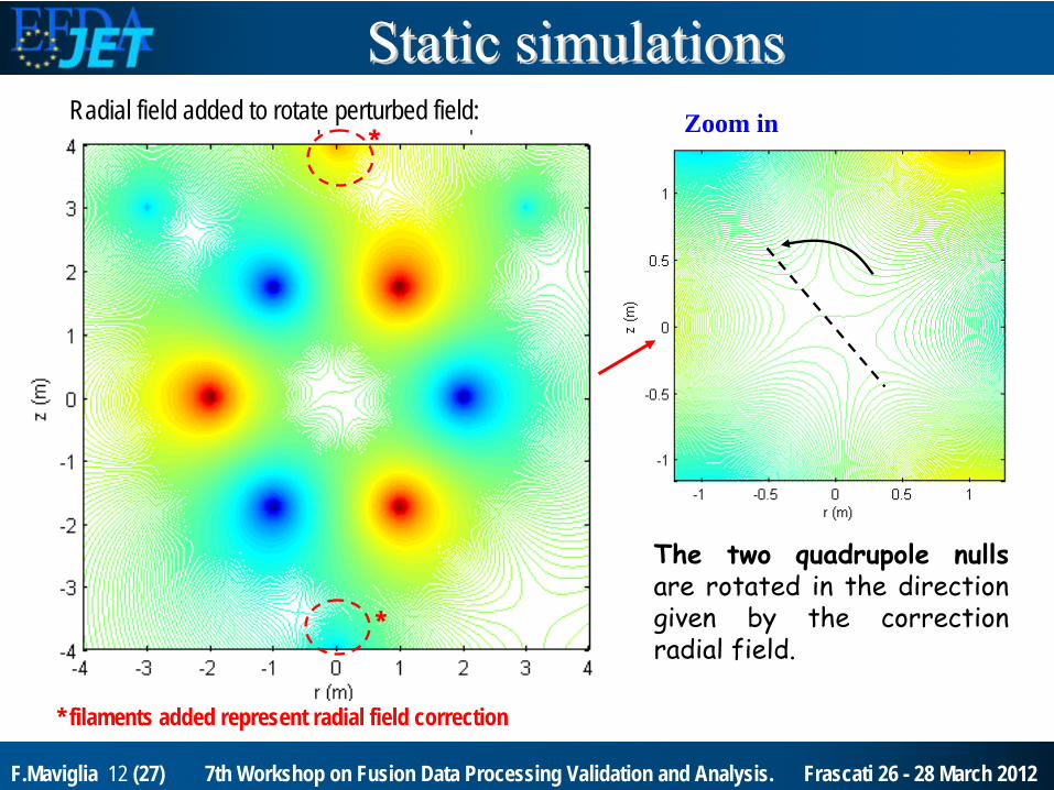
Radial field added to rotate perturbed field: Zoom in
The two quadrupole nulls are rotated in the direction
given by the correction radial field.
* filaments added represent radial field correction
*
*
StaticStatic simulationssimulations

F.Maviglia 13 (27) 7th Workshop on Fusion Data Processing Validation and Analysis. Frascati 26 - 28 March 2012
Optimization of field null position during breakdown Aims:
Place the null field position far from the inner divertor region.
Solution:
Rotate the 2 quadrupole field nulls by applying an offset radial field bias.
2 3 4−2.5
−2
−1.5
−1
−0.5
0
0.5
1
1.5
2
2.50 ms
R [m]
Z [m
]
IP1 −20.0 [kA]IP4 258 [A]IFRFA −2 [A]Other PF 0 [A]
ΔΨ = 0.01 Vs iso B= [0.5;1;1.5;2;2.5;] mT
Flu
x
2 3 4−2.5
−2
−1.5
−1
−0.5
0
0.5
1
1.5
2
2.50 ms
R [m]
IP1 −20.0 [kA]IP4 258 [A]IFRFA 118 [A]Other PF 0 [A]
ΔΨ = 0.01 Vs iso B= [0.5;1;1.5;2;2.5;] mT
Flu
x
2 3 4−2.5
−2
−1.5
−1
−0.5
0
0.5
1
1.5
2
2.50 ms
R [m]
IP1 −20.0 [kA]IP4 258 [A]IFRFA 358 [A]Other PF 0 [A]
ΔΨ = 0.01 Vs iso B= [0.5;1;1.5;2;2.5;] mT
Flu
x
2 3 4−2.5
−2
−1.5
−1
−0.5
0
0.5
1
1.5
2
2.50 ms
R [m]
IP1 −20.0 [kA]IP4 258 [A]IFRFA 238 [A]Other PF 0 [A]
ΔΨ = 0.01 Vs iso B= [0.5;1;1.5;2;2.5;] mT
Flu
x
Standard radial bias =0A radial bias =+120A radial bias =+240A radial bias =+360A
-In the cases with radial
bias
≠0 the upper inner field null expected to be preferred for plasma formation due to higher electrical field.
Static sim
all at 40s: Increasing radial field bias
→ quadrupoles
rotation
StaticStatic simulationssimulations

F.Maviglia 14 (27) 7th Workshop on Fusion Data Processing Validation and Analysis. Frascati 26 - 28 March 2012
kl1-o4wb-raw @40.04:
Pulse #80400, std. radial bias =0
kl1-o4wb slow camera (40ms) first visible frame: plasma starts in an upper inner wall position with radial bias correction, far from divertor region.
kl1-o4wb-raw @40.03:
Pulse #80402, radial bias =+240A
ExperimentalExperimental
resultsresults
mode D mode D --20kA 20kA premagpremag

F.Maviglia 15 (27) 7th Workshop on Fusion Data Processing Validation and Analysis. Frascati 26 - 28 March 2012
-20.0 -19.0
-18.0
-17.0
103
A
0.2 0.4 0.6 0.8 1.0 1.2
103
A
0.0
1.0
2.0
103 A
-4.0 -3.0 -2.0 -1.0 0.0
105V
0.00.51.01.52.0
2.5
a.u.
40.00 40.02 40.04 40.06SEC.
-2.0 -1.5 -1.0 -0.5 0.0
105
A
80400 80401 80402 80404
IP1 (primary)
IP4 (vertical)IERFA (radial)
VFB (vertical velocity control request)
HALPHA
Plasma current
0,std120A240A*360A
•Higher velocity loop control for st. pulses
•Higher radial field current peak for standard pulse.
•Plasma curr.>47kA, velocity loop “ON”
Radial bias:
*radial bias =+240A optimum predicted by sim.: exp. verified.
ExperimentalExperimental
resultsresults
mode D mode D --20kA 20kA premagpremag

F.Maviglia 16 (27) 7th Workshop on Fusion Data Processing Validation and Analysis. Frascati 26 - 28 March 2012
0.0
1.0
2.0
103
A
-4.0
-3.0
-2.0
-1.0
0.0
105
A
40.00 40.02 40.04 40.06SEC.
-1.0
-0.5
0.0
0.5
1.0
1.5
104
A
80400 80401 80402 80404
IERFA (radial)
VFB (vertical velocity control request)
std pulse
VFB (vertical velocity control request)
optimized
Radial bias:0,std120A240A360A
Velocity loop control peaks (≈105V) when plasma pulled up from divertor region for std pulses.
Moderate control action for optimized pulses. ∆IERFA in time interval of interest decrease form 3.2kA to 0.7kA: factor ≈4.
2.5kA peak std. pulse: amplifier limit =5kA
standard(radial bias=0)
optimized (radial bias=+240A)
time interval of interestExperimentalExperimental
resultsresults
mode D mode D --20kA 20kA premagpremag
VV

F.Maviglia 17 (27) 7th Workshop on Fusion Data Processing Validation and Analysis. Frascati 26 - 28 March 2012
-20.0 -19.0
-18.0
-17.0
103
A
0.2 0.4 0.6 0.8 1.0 1.2
103
A
-1.0 0.0 1.0 2.0 3.0 4.0 5.0
103
A
-1.5
-1.0
-0.5
0.0
106
V
-2.5 -2.0 -1.5 -1.0 -0.5 0.0
105
A
40.00 40.02 40.04 40.06SEC.
0.00.20.40.60.81.01.21.4
a.u.
81755 81756 81757 81758
IERFA (radial)
IP4 (vertical)IP1 (primary)
VFB (vertical velocity control request)
plasma current
HALPHA
Radial bias (A):0,marginal0,NSB0,NSB+360, ok
•∆IERFA (≈4kA) for 0 bias pulses, limits (±5kA)
upper lim.
•Larger vertical velocity request for zero radial bias pulses
NSB
I0Z limit scan
for -20kA breakdown
•Non
Sustained Breakdown
(NSB) or
marginal for radial bias=0.
ExperimentalExperimental
resultsresults
mode D mode D --20kA 20kA premagpremag

F.Maviglia 18 (27) 7th Workshop on Fusion Data Processing Validation and Analysis. Frascati 26 - 28 March 2012
−100 0 100 200 300 400 5000
1
2
3
4
5Mode D: Premag −20kA
IERFA @40s (A) (radial field bias)ΔIER
FAm
ax (
kA) i
n ra
nge
of in
tere
st
radial bias =0
(std.)
min
Statistic all mode D breakdown.
ΔIERFA reduction factor ≈4 from std.
Statistic on all successful mode D breakdown with new VS system (named V5) measurements tuned with a precision lower then ±50A.
radial bias scan
figure of merit:
min (min (∆∆IERFA)IERFA)for t
time interval:•
|Plasma current| > 47 kA (velocity loop on) up to •40.065s (plasma in outer limiter).
ExperimentalExperimental
resultsresults
mode D mode D --20kA 20kA premagpremag

F.Maviglia 19 (27) 7th Workshop on Fusion Data Processing Validation and Analysis. Frascati 26 - 28 March 2012
0
1000
2000
40 40.01 40.02 40.03 40.04 40.05 40.06
−4
−3
−2
−1
0
x 10
5a.
u.
sec
IERFA
VFB (velocity loop control request)
A
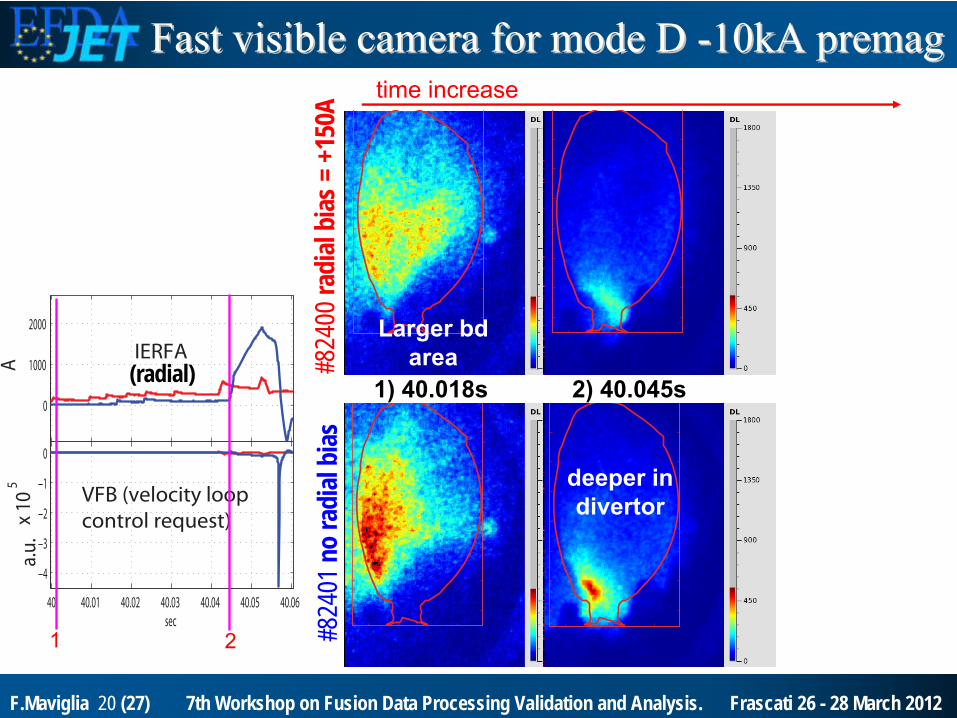
1) 40.018s
time
increase
Fast visible camera for mode D Fast visible camera for mode D --10kA premag10kA premag
1 #824
01no
radi
albi
as#8
2400
radi
albi
as= +
150A
(radial)
Larger bdarea
F.Maviglia 20 (27) 7th Workshop on Fusion Data Processing Validation and Analysis. Frascati 26 - 28 March 2012
0
1000
2000
40 40.01 40.02 40.03 40.04 40.05 40.06
−4
−3
−2
−1
0
x 10
5a.
u.
sec
IERFA
VFB (velocity loop control request)
A
1) 40.018s
time
increase
deeper
in divertor
2) 40.045s
Fast visible camera for mode D Fast visible camera for mode D --10kA premag10kA premag
1 #824
01no
radi
albi
as#8
2400
radi
albi
as= +
150A
2
(radial)
Larger bdarea

F.Maviglia 21 (27) 7th Workshop on Fusion Data Processing Validation and Analysis. Frascati 26 - 28 March 2012
0
1000
2000
40 40.01 40.02 40.03 40.04 40.05 40.06
−4
−3
−2
−1
0
x 10
5a.
u.
sec
IERFA
VFB (velocity loop control request)
A
3
1) 40.018s
time
increase
Plasma touches upper wall
deeper
in divertor
2) 40.045s 3) 40.058s
Fast visible camera for mode D Fast visible camera for mode D --10kA premag10kA premag
1 #824
01no
radi
albi
as#8
2400
radi
albi
as= +
150A
2
(radial)
Larger bdarea

F.Maviglia 22 (27) 7th Workshop on Fusion Data Processing Validation and Analysis. Frascati 26 - 28 March 2012
40.445s1.5 2 2.5 3 3.5 4 4.5
−2.5
−2
−1.5
−1
−0.5
0
0.5
1
1.5
2
2.5
R [m]
Z [m
]
1.5 2 2.5 3 3.5 4 4.5−2.5
−2
−1.5
−1
−0.5
0
0.5
1
1.5
2
2.5
R [m]
Z [m
]
1.5 2 2.5 3 3.5 4 4.5−2.5
−2
−1.5
−1
−0.5
0
0.5
1
1.5
2
2.5
R [m]
Z [m
]
1.5 2 2.5 3 3.5 4 4.5−2.5
−2
−1.5
−1
−0.5
0
0.5
1
1.5
2
2.5
R [m]
Z [m
]
P4 (vertical field) bias
0.400.420.440.460.480.50
0.0 0.2 0.4 0.6 0.8 1.0
10
3
A
200300400500600
0.0
0.5
1.0
1.5
a.u
.
40.40 40.45 40.50 40.55SEC.
-1.5
-1.0
-0.5 0.0
10
5
A
81627 low IP4 bias 81628 high IP4 bias
VLOOP (primary)
IP4 (vertical)
IERFA (radial)
HALPHA
IPLA
A
V/m
Different IP4
(vertical field) dynamic induces different eddy currents dynamics: magnetic null enters in the chamber*
later -> delayed breakdown.
8162
7 81
628
*dynamic simulations
E @ r = 2.95mE0 ≈0.48V/m
ExperimentalExperimental
resultsresults
forfor
mode B high Emode B high E00
40.475s
*

F.Maviglia 23 (27) 7th Workshop on Fusion Data Processing Validation and Analysis. Frascati 26 - 28 March 2012
40.512 s
Mode B low Electric field Mode B low Electric field ““ITER likeITER like””82076 radial bias= -50A
82074 radial bias= 0
82077 radial bias= +50A
82078 radial bias= +100A
82076820748207782078
Radial
bias: -50A
0A+50A
+100A
centered
Same initial iron magnetization as
mode D
E0 ≈0.3V/m

F.Maviglia 24 (27) 7th Workshop on Fusion Data Processing Validation and Analysis. Frascati 26 - 28 March 2012
40.512 s
40.566 s
divertor
Mode B low Electric field Mode B low Electric field ““ITER likeITER like””82076 radial bias= -50A
82074 radial bias= 0
82077 radial bias= +50A
82078 radial bias= +100A
82076820748207782078
Radial
bias: -50A
0A+50A
+100A
centered
E0 ≈0.3V/m

F.Maviglia 25 (27) 7th Workshop on Fusion Data Processing Validation and Analysis. Frascati 26 - 28 March 2012
40.512 s
40.566 s
40.574s
failed
E0 ≈0.3V/m
divertor
•E0 <0.3V/m not achievable without error field optimization (i.e. radial bias).•Min. electric field E0 ≈0.25V/m (pulse #82081),with radial bias = +100A.
Mode B low Electric field Mode B low Electric field ““ITER likeITER like””82076 radial bias= -50A
82074 radial bias= 0
82077 radial bias= +50A
82078 radial bias= +100A
centered

F.Maviglia 26 (27) 7th Workshop on Fusion Data Processing Validation and Analysis. Frascati 26 - 28 March 2012
Up-down asymmetric iron gap modelling activity. Radial field ≈0.5mT at r=2.95m, for fully saturated iron.
This leads to split the ideal hexapolar null in two
quadrupolar
nulls.
Static and dynamic optimization to optimize the plasma formation region in the upper inner wall, far from divertor zone.
Accurate model, with a precision of a fraction of mT, has been employed for magnetic null position scan.
Fast visible camera
used to validate optimized plasma starting position
and dynamic evolution.
ConclusionsConclusions

F.Maviglia 27 (27) 7th Workshop on Fusion Data Processing Validation and Analysis. Frascati 26 - 28 March 2012
Optimized breakdown avoids the plasma to be pushed in the divertor region as for the past pulses. Non optimized breakdowns are more fragile with a number of NSB.
VS system
improved
behavior, with smaller radial field current excursion (factor ~4), farther from amplifier limits.
Re-established at JET low electric field “ITER like” breakdown using I0Z bias:
mode D min E0
≈0.27V/m with premag
= -7kA;
mode B min E0
≈0.25V/m.
Low electric field pulses breakdown success particularly sensitive to error field optimization: ITER E0
= 0,33V/m.
ConclusionsConclusions