Embed Size (px)
Citation preview

Adv. Theor. Appl. Mech., Vol. 5, 2012, no. 3, 145 - 159
Optimization of the Electrical Motor Generator
in Hybrid Automobiles
Sayel M. Fayyad, Mohammed Abuzalata, Muntaser Momani
and Suleiman Abu-Ein
Al-Balqa’ Applied University, Faculty of Engineering Technology
11140 P.O. Box 425530 Amman, Jordan
[email protected] (S. M. Fayyad)
Abstract
The development of internal combustion engine vehicles especially automobiles, is
one of the greatest achievements of modern technology. However, the large number
of automobiles in use around the world has caused and continues to cause serious
problems for the environment and human life. Air pollution, global warming, and the
rapid depletion of the Earth's petroleum resources are now problems of paramount
concern. Automobile hybrid systems combine any two or more motive power sources,
such as an internal combustion engine and an electric motor, to take advantage of the
benefits provided by these power sources while compensating for each other
shortcomings, resulting in highly efficient driving performance. The hybrid
automobiles have many problems in electrical motor generator, such as low power
and low charging to hybrid vehicle battery.
Keywords: hybrid systems, electrical motors, generators, batteries
1 INTRODUCTION
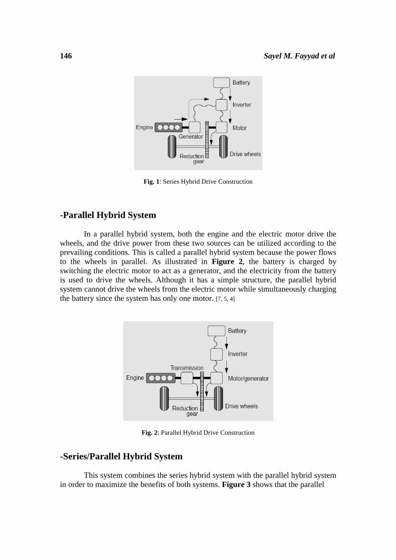
There are many types of hybrid arrangements: series and parallel, in series
arrangements: the engine drives a generator, and an electric motor uses this generated
electricity to drive the wheels. This is called a series hybrid system because the power
flows to the wheels in series. As shown in Figure 1, series hybrid system can run a
small output engine in the efficient operating region relatively steadily, generate and
supply electricity to the electric motor and efficiently charge the battery. It has two
motors a generator (which has the same structure as an electric motor) and an electric
motor. This system is being used in the Coaster Hybrid. [7, 5, 4]
146 Sayel M. Fayyad et al
Fig. 1: Series Hybrid Drive Construction
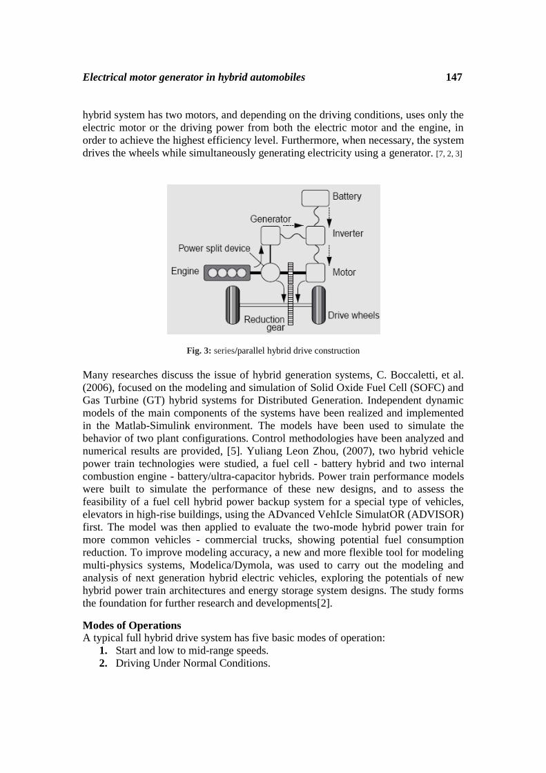
-Parallel Hybrid System
In a parallel hybrid system, both the engine and the electric motor drive the
wheels, and the drive power from these two sources can be utilized according to the
prevailing conditions. This is called a parallel hybrid system because the power flows
to the wheels in parallel. As illustrated in Figure 2, the battery is charged by
switching the electric motor to act as a generator, and the electricity from the battery
is used to drive the wheels. Although it has a simple structure, the parallel hybrid
system cannot drive the wheels from the electric motor while simultaneously charging
the battery since the system has only one motor. [7, 5, 4]
Fig. 2: Parallel Hybrid Drive Construction
-Series/Parallel Hybrid System
This system combines the series hybrid system with the parallel hybrid system
in order to maximize the benefits of both systems. Figure 3 shows that the parallel
Electrical motor generator in hybrid automobiles 147
hybrid system has two motors, and depending on the driving conditions, uses only the
electric motor or the driving power from both the electric motor and the engine, in
order to achieve the highest efficiency level. Furthermore, when necessary, the system
drives the wheels while simultaneously generating electricity using a generator. [7, 2, 3]
Fig. 3: series/parallel hybrid drive construction
Many researches discuss the issue of hybrid generation systems, C. Boccaletti, et al.
(2006), focused on the modeling and simulation of Solid Oxide Fuel Cell (SOFC) and
Gas Turbine (GT) hybrid systems for Distributed Generation. Independent dynamic
models of the main components of the systems have been realized and implemented
in the Matlab-Simulink environment. The models have been used to simulate the
behavior of two plant configurations. Control methodologies have been analyzed and
numerical results are provided, [5]. Yuliang Leon Zhou, (2007), two hybrid vehicle
power train technologies were studied, a fuel cell - battery hybrid and two internal
combustion engine - battery/ultra-capacitor hybrids. Power train performance models
were built to simulate the performance of these new designs, and to assess the
feasibility of a fuel cell hybrid power backup system for a special type of vehicles,
elevators in high-rise buildings, using the ADvanced VehIcle SimulatOR (ADVISOR)
first. The model was then applied to evaluate the two-mode hybrid power train for
more common vehicles - commercial trucks, showing potential fuel consumption
reduction. To improve modeling accuracy, a new and more flexible tool for modeling
multi-physics systems, Modelica/Dymola, was used to carry out the modeling and
analysis of next generation hybrid electric vehicles, exploring the potentials of new
hybrid power train architectures and energy storage system designs. The study forms
the foundation for further research and developments[2].
Modes of Operations
A typical full hybrid drive system has five basic modes of operation:
1. Start and low to mid-range speeds.
2. Driving Under Normal Conditions.

148 Sayel M. Fayyad et al
3. Sudden Acceleration.
4. Deceleration.
5. Battery Recharging.
-Start and Low to Mid-Range Speeds
The engine stops when in an inefficient range, such as at start-up and in low
to mid-range speeds. The vehicle runs on the motor alone. See (Figure 4). [6]
Fig.4: Start and Low to Mid-Range Speeds Mode
- Driving Under Normal Conditions
Engine power is divided by the power split device. Some of the power turns
the generator, which in turn drives the motor. (B), the rest of the power drives the
wheels directly. (C) Power allocation is controlled to maximize efficiency. See
(Figure 5). [8,6]
Fig.5: Driving Under Normal Conditions Mode

Electrical motor generator in hybrid automobiles 149
- Sudden Acceleration
Figure 6 shows the Sudden Acceleration mode, Extra power is supplied from
the battery (A), while the engine and high-output motor provide smooth response
(B+C) for improved acceleration characteristics. [8,6]
Fig.6: Sudden Acceleration Mode
- Deceleration The high-output motor acts as a high-output generator, driven by the vehicle’s
wheels. This regenerative braking system recovers kinetic energy as electrical energy,
which is stored in the high-performance battery. See (Figure 7). [6, 2]
Fig.7: Deceleration Mode
- Battery Recharging Battery level is managed to maintain sufficient reserves. See (Figure 8), the
engine drives the generator to recharge the battery when necessary, [6].

150 Sayel M. Fayyad et al
Fig.8: Battery Recharging Mode
-Motor Generator of Hybrid Vehicle
Type of motor generator in hybrid vehicle:
1- Motor generator one MG1.
2- Motor generator two MG2.
MG1 and MG2 function as both highly efficient alternating current synchronous
generators and electric motors, MG1 and MG2 also as sources of supplemental motive
force that provide power assistance to the engine as needed. Both the MG1 and the
MG2 are compact, lightweight, and highly efficient alternating current permanent
magnet synchronous type. [10]. Serving as the source of supplemental motive force that
provides power assistance to the engine as needed, the electric motor helps the vehicle
achieve excellent dynamic performance, including smooth start-offs and acceleration.
When the regenerative brake is activated, MG2 converts the vehicle’s kinetic energy
into electrical energy, which is then stored in the HV battery. [10]. MG1 recharges the
HV battery and supplies electrical power to drive MG2. In addition, by regulating the
amount of electrical power generated (thus varying the generator’s rpm), MG1
effectively controls the continuously variable transmission function of the transaxle.
MG1 also serves as the starter to start the engine. A cooling system via water pump for
the MG1 and MG2 has been added. See (Figure 9) A and B. [10]

Electrical motor generator in hybrid automobiles 151
Fig. 9 A: MG1 generates electrical power and starts the engine.
Fig. 9 B: MG2 drives the vehicle.
Electrical Model Synchronously rotating reference frame can be used in design optimization and evaluation.
In this model the flux distribution in the air gap is assumed to be sinusoidal and the iron
loss and magnetic saturation are not considered.
The motor vector diagram is shown in (Figure 10). Voltage equations are expressed as
follows:
The motor torque is then obtained as:
Where and are the d-axis and q-axis components of the stator current vector Is.

152 Sayel M. Fayyad et al
Fig. 10: Vector diagram of PMSM
Thus the magnitude of IS is given by:
Since a PM motor torque depends on the stator current vector components as well as
the motor parameters, the design optimization is carried out under the condition of
maximum torque per Ampere control. This condition can be as obtained from last equations
such as:
Where: and
As mentioned above, maximum speed and cost of motor is chosen for optimization. The
price of permanent magnet is very high in comparison with other material of PMSM.
Therefore we can approximately use consumed magnet volume instead of motor cost.For
HEV applications the case of b is the best case see (figure 11). Therefore in the
optimization we should keep normalized flux linkage to normalized direct inductance close
to one.

Electrical motor generator in hybrid automobiles 153
Fig.11: torque diagram for all motor generators a) , b) , c)
- Power Calculations The mechanical power for the motor generator is :
where is torque motor and is angular velocity .The electrical power for the motor
generator is :
where and are the voltage and current motor generator respectively.
When the power is transfer from the electrical mode to the mechanical mode, the few losses
occur thus the electrical power greater than the mechanical power.
Note: Assume the losses equal zero, then the electrical power equal mechanical power.
2 RESULTS AND DISCUSSION
Figure 12 shows relation between power and motor angular speed it can be noticed
that steady state power value closes to .

154 Sayel M. Fayyad et al
Fig.12: torque diagram for optimized motor generators
The main idea here is to make use of the mechanical motion that produces the
rotational motion for the wheels, by converting this mechanical energy into electrical
energy. And supply the motor generator 2 (MG2) with this electrical power. This way
we raise the motor generator efficiency and reduce the work of the internal
combustion engine figure 13.
Fig.13: hybrid system

Electrical motor generator in hybrid automobiles 155
The hybrid vehicle works on two different power resources or more; in our
project they are the electrical engine and the gasoline engine. Determining of which of
these two different engines would be used at a given time depends on operating
environment and the vehicle load. In short, when we have heavy loads, the electrical
engine cannot provide enough power, so the internal combustion engine works at this
time and provide the necessary power for the vehicle since the gasoline engine is
capable of providing much more power see table 1.
Table 1: power and torque for engine and MG
Engine MG Engine+ Mg
Torque 57 kW 50 kW 478
Power 115 N.M 400 82
The goal behind this study is to reduce fuel consumption which is non-
renewable energy source, and produces pollution when burns, which negatively affect
the environment. Making the electrical engine to work with higher efficiency means
that it is capable of moving the vehicle in harsh working conditions without the need
to activate the internal combustion engine.
-New idea
The vehicle movement on the road is done by rotating the wheels, where the
power that is produced by the electrical engine or by the gasoline engine transforms
into rotational movement. We used this rotational movement to generate electrical
power through the principle of electric induction (Figure 14), where the electrical
coils and the rotational parts on the wheel are used to generate electrical force. The
type of the generated force is alternative current – 3 phases (AC-3ph).
Fig.14: motor generator
The end of axial that is out of the gear box is attached to the disk. We added
three small poles on the wheel flange and cylindrical plate (disk break) that have the
coils - the fixed part. When adding a coil on the fixed part and other coils on the rotor

156 Sayel M. Fayyad et al
part then introduced an inflammatory current to the stator coil an inductive current
arises in the rotor coils. The field lines (flux) intercut and provide an alternative
current in these coils – electrical principle, (Figure 15) the introduction of the
inflammatory current to the coils is done by using slip rings with 12 volts from the
auxiliary battery. And we used it for safety connection to the coils.
Fig.15: motor generator front section
The generated output current is directly proportional with the wheel revelation
per minute (RPM). And this is alternative current 3 phase. Because the wheel rotation
(RPM) is not constant, the generated current is inconstant in frequency and amplitude.
So we cannot use this current to move any type of electrical motors since all the
motors works on constant frequency and constant amplitude. In order to solve this
problem we designed an electrical circuit (inverter) to get constant frequency and
constant amplitude see (Figure 16). This is done by inverting the alternative current
to direct current by using diodes and then storing the new output in a storage (battery)
and then return it to alternative current 3 phase, so it can be used for different
purposes.
Fig.16: inverter circuit

Electrical motor generator in hybrid automobiles 157
The generated signal from the previous inverter is a square wave, and this is
another problem, because the motor generator gives more efficiency if the signal is
sine wave, so we designed an electrical circuit (converter), to convert the square wave
into a sine wave; see (Figure 17 A and B).
Fig. 17 A: integrator - converter circuit
Fig. 17 B: converting from square wave to sine wave

158 Sayel M. Fayyad et al
3 CONCLUSIONS
Through the calculations on both typical and optimized, it can be noticed that the
typical motor achieved the case of (c) and optimized motor achieved the case of (b)
, and during our study of torque diagram, the optimized motor is the best than the
typical motor , because fast and steady of responsibility. It can concluded from during
applied equation on the typical and optimized motor that power, voltage and torque
motor in optimized motor greater than the typical motor, thus the optimized motor
better than the typical motor. Hybrid vehicles combine the advantages of the
traditional and electric vehicles. The machines are fed from AC sources and can be
single-phase or multiple-phase types. Single-phase AC machines are used for low-
power appliance applications, while higher-power machines are always of three-phase
configuration. The motor drive must be capable of handling voltage fluctuations from
the source. Another important requirement of the electric motor is acceptable mass
production costs, which is to be achieved through technological advancement. The
primary difference between AC machines and DC machines is that the armature
circuit of the former is located in the stationary piece of the structure. The major
advantage of this arrangement is the elimination of the commutator and brushes of
DC machines.
REFERENCES
[1] Automotive training and resource site, Toyota motor sale:
http://www.autoshop101.com/technical articles.
[2] C. Boccaletti, G. Fabbri, O. Riot, E. Santini, Modeling and simulation of hybrid
SOFC-GT systems for Distributed Generation Department of Electrical Engineering
University of Rome "La Sapienza" Via Eudossiana 18, 00184 Rome, Italy e-mail:
[email protected]; [email protected].
[3] H. Iqbal, Electric and Hybrid Vehicle Design Fundamentals. CRC Press; 1 edition
March 12, 2003.
[4] J. Stephen J., Electrical Machinery Fundamentals. McGraw-Hill
Science/Engineering/Math; 4 edition (October 3, 2003).
[5] K. Geoff, Operation And Maintenance Of Large Turbo-Generators (Toronto,
Ontario Canada) And Isidor Kerszenbanm (Irvine, California USA). August 11, 2004.
[6] L. Y. Yuliang, 2007, "Modeling and Simulation of Hybrid Electric Vehicles B.
Eng., University of Science & Tech. Beijing, 2005 A Thesis Submitted in Partial
fulfillment of the Requirements for the Degree of MASTER OF APPLIED SCIENCE
in the Department of Mechanical Engineering University of Victoria.
[7] M. Ehsani, K.M. Rahman, and H. A. Toliyat, Propulsion system design for electric
and hybrid vehicles,IEEE Transactions on Industrial Electronics, Vol. 44, No. 1,
February, 1997, pp. 19–27.
[8] Oak Ridge National Laboratory Mitch Olszewski, Program Manager Evaluation
of 2004 Toyota Prius Hybrid Electric Drive System Prepared.

Electrical motor generator in hybrid automobiles 159
[9] O.M. Mosa, Loay T.D. Al-Sardy, and Mohammad M.H Al-Makableh.
2010, Project Research about the Hybrid Vehicle Technology, Al-Balqa' Applied
University, Faculty of Engineering Technology, Mechanical Engineering Department
[10] R. Tony, Kuphald, Lessons In Electric Circuits, Volume II – AC Sixth Edition,
Last Update July 25, 2007.
Received: January, 2012