Embed Size (px)
Citation preview

C21_ 03 8 10C21_119 1
Optimization of the Counter-Flow Heat Exchangers of Space 2.5 K Hybrid Joule-Thomson Cryocooler
Z .Y. L iu1,2, Y.X . Ma1, L .J . W ei1, J . Q uan1, Y.J . L iu1, J .T. L iang1,2
1Key L aboratory of Space Energy Conversion Technology, Technical Institute of Physics and Chemistry, CAS, B eijing 10019 0, China2University of Chinese Academy of Sciences, B eijing 100049 , China
ABSTRACTHeat ex changers are, among others, the key components of hybrid Joule-Thomson (JT) cryocoolers.
Three tube-in-tube counter-flow heat exchangers (CFHX) are used in our hybrid JT cooler. Among them, the 3rd stage counter-flow heat exchanger of JT cycle has the important role of precooling high pressure rd stage counter-flow heat exchanger of JT cycle has the important role of precooling high pressure rd
gas before throttling. To make the structure of hybrid JT cryocooler more compact, a new high-efficiency 3rd stage counter-flow heat exchanger is designed and will be used in a JT cryocooler.rd stage counter-flow heat exchanger is designed and will be used in a JT cryocooler.rd
INTRODUCTIONIn recent years, it is becoming more prevalent for JT cryocoolers to be used in space ex ploration.
JT cryocoolers have higher efficiency at temperatures near and below 4 K than other kinds of me-chanical cryocoolers and can isolate vibration and shield electromagnetic interference easily because there are no moving parts at the cryocoolers’ cold ends.
Counter-flow heat exchangers which have high efficiency and compact structures are principal components of hybrid JT cryocoolers. This kind of heat exchanger can be compactly integrated with the pre-cooling stages, such as multi-stage pulse tube or Stirling cryocooler. In addition, counterflow heat ex changers make full use of the cooling capacity of recuperated cold helium to pre-cool the high pressure incoming helium.
In 2018 , a 2.65 K hybrid JT cooler using 4He as working medium were developed by the Key L aboratory of Space Energy Conversion Technology, CAS. This hybrid JT cryocooler obtained the temperature of 2.65 K with total power consumption of 317.3 W and cooling capacity of 1.48 mW at 2.71 K [1]. The three counter-flow heat exchangers used in this hybrid JT cryocooler are spiral tube-in-tube design as Figure 1 shows. The high pressure helium which comes out from the 3rd stage
F igure 1. Diameters of tubes of the counter-flow heat exchanger.
Cryocoolers 21, edited by R.G. Ross, Jr., J.R. Raab and S.D. Miller© International Cryocooler Conference, Inc., Boulder, CO, 2021 453

C21_119 2
counter-flow exchanger directly enters in the JT valve for throttling. So, the efficiency of the 3rd
stage counter-flow heat exchanger directly impacts the performance of the JT cycle.In this paper, a new compact 3rd stage CFHX is designed, which will improve the performance
of the hybrid JT cryocooler.
MATHE MATICAL MODE L ING AND COMP UTATION
Flow regime of the fluid in CFHXsThe 3rd stage CFHX is directly connected with the JT valve, and its heat exchange efficiency rd stage CFHX is directly connected with the JT valve, and its heat exchange efficiency rd
directly impacts the cooling performance of the JT cycle. The previous 3rd stage heat ex changer has rd stage heat ex changer has rd
a large spiral radius taking up a lot of volume. To reduce the volume and improve the efficiency of the 3rd stage heat exchanger, we can reduce the spiral diameter, increase the heat exchanger length, rd stage heat exchanger, we can reduce the spiral diameter, increase the heat exchanger length, rd
and reduce tube diameter. According to our previous experiments, when this JT cryocooler obtains a temperature of 3 K,
the parameters of the 3rd stage CFHX are estimated and shown in therd stage CFHX are estimated and shown in therd Table 1. The first step of optimizing the 3rd stage CFHX is determining the proper tube diameter of rd stage CFHX is determining the proper tube diameter of rd
CFHX with a certain spiral diameter of 40 mm. According to our previous study, six groups of CFHXs are discussed, as Table 2 shows. Then, the spiral diameter will be optimized.
Reynolds number is commonly used to judge the flow regime of fluid. The critical Reynolds number of the spiral tube is calculated with the following formula [2]. This calculation ignores the pressure drop inside the heat ex changer.
(1)
where Rec is critical Reynolds number, D is spiral diameter of CFHX.According to calculation results of Reynolds numbers in different tubes with mass flow rate
from 1.0 mg/s to 2.0 mg/s, the flow regime is summarized in the Table 2. The flow regime of the fluid inside these six CFHXs is laminar.
0.45Re 2300(1 8 .6( ) )ic
dD
= +
Tab l e 1. The estimated parameters of the 3rd stage CFHX when JT cycle obtained 3K.
*The saturated vapor pressure of helium is 0.02373 MPa at 3K. Due to the distance between the evaporator and the inlet of inner tube, it is conservatively estimated that the inlet pressure of the inner tube is 0.025 MPa.
Tab l e 2. The parameters of six CFHXs.
C21_119
J -T CRYOCOOLER DEVELOPMENT454

In this paper, a new compact 3rd stage CFHX is designed, which will improve the performance of the hybrid JT cryocooler.
Rec
0.45Re 2300(1 8 .6( ) )ic
dD
= +
C21_119 3
The effectiveness of CFHXs and the temperature of outletsFigure 2 shows the schematic diagram of CFHX. Ti and To are the temperatures of high pres-
sure helium of inlet and outlet, respectively. ti and to are the temperatures of low pressure helium of inlet and outlet, respectively.
The specific heat capacity at 0.9 MPa and 0.025 MPa are shown in the Figure 3. The effective-ness of the heat exchanger is the ratio of the actual heat flow to the theoretical maximum heat flow, which is set to 97%.
(2)
(3)
where Q’ is the heat flow of high pressure helium released, Q’’ is the heat flow of low pressure he-lium absorbed, ε is effectiveness of heat exchanger and Qs is the smaller value between Q’ and Q’’.
F igure 2. Schematic diagram of fluid temperature in CFHX.
F igure 3. The specific heat capacity of helium at 0.9 MPa and 0.025 MPa.
COUNTER-FLOW HEAT EX CHANGERS OF 2. 5 K HYBRID J -T 455

C21_119 4
According to the effectiveness of heat ex changer and design parameters, outlet temperatures of inner and outer tubes can be calculated as Table 3 shows.
Then, according to these four temperatures of inner and outer tubes, the logarithmic mean temperature difference (LMTD) can be obtained [5].
(4)
(5)
(6)
where Δtm is the logarithmic mean temperature difference.
Heat transfer coefficient of CFHXsThe Nusselt number of a spiral tube using gas as working fluid can be obtained by multiplying
the Nusselt number of a straight tube by a correction factor – cr. The heat transfer coefficient of CFHX are calculated by these following formulas [2-5].
(7)
(8)
(9)
(10)
(11)
where K is the total heat transfer coefficient, K is the total heat transfer coefficient, K α' and α'' are the convective heat transfer coefficient of outer and inner tube respectively, λ is heat conductivity coefficient of fluid, λs is heat conductivity coefficient of the material of tubes. Nu is Nusselt number of a straight tube, and G z is the Graetz number. G z is the Graetz number. G z
max min
max
min
lnm
t tt tt
∆ − ∆∆ =
∆∆
*0.67
0.06683.6571 0.04
G zN uG z
= ++
2
1
*
2 1
( )t
tr
N u t dtN u c
t t=
−∫
1 1.77rdcR
= +
Tab l e 3. The calculation results of temperature of CFHX.
Tab l e 4. The calculation results of heat transfer coefficient.
C21_119
p∆
QSK t
=∆
12.220.45
0.511.61 1
Ref
e
cdD
− = − −
J -T CRYOCOOLER DEVELOPMENT456

max min
max
min
lnm
t tt tt
∆ − ∆∆ =
∆∆
*0.67
0.06683.6571 0.04
G zN uG z
= ++
2
1
*
2 1
( )t
tr
N u t dtN u c
t t=
−∫
1 1.77rdcR
= +
C21_119 5
The heat transfer coefficient of the six CFHXs are shown in Table 4. It can be seen that the heat transfer coefficient has a close relationship with hydraulic diameters of outer and inner tubes. The smaller the hydraulic diameter, the greater the heat transfer coefficient.
The length of CFHXs After obtaining the total heat transfer coefficient, the required heat transfer area can be obtained.
The length of CFHXs with different mass flow rate can be calculated by these following formulas.(12)
(13)
where S is the heat transfer area of CFHX. S is the heat transfer area of CFHX. S L is the length of heat ex changer.Figure 4 shows the calculation results of the length of CFHXs at different mass flow rates.
As the mass flow rate increases, to maintain the same efficiency of heat exchange, the length of the heat exchanger will also increase. At a certain flow rate, the lengths of 2nd and 3nd and 3nd rd group are rd group are rd
shorter than others, which proves that these two groups of CFHXs take up less space. Because the hydraulic diameter of outer tube of the 4th group is relatively large and the outer diameter of inner tube is small, the 4th group is much longer than others.
However, all the calculation are performed under ideal conditions without considering pressure changes.
The pressure drop of CFHXsThe resistance of fluid in spiral tubes is different from that in straight tubes. The pressure drop
in spiral tubes can be calculated by multiplying the pressure drop of straight tubes by a correction factor - cf [2].
(14)
(15)
where p∆ is the pressure drop of CFHX, f is friction coefficient of laminar flow.
QSK t
=∆
12.220.45
0.511.61 1
Ref
e
cdD
− = − −
F igure 4. The calculation results of length of six CFHXs.
COUNTER-FLOW HEAT EX CHANGERS OF 2. 5 K HYBRID J -T 457

C21_119 6
Figure 5 shows the calculation results of pressure drop of these 6 groups. With the decrease of hydraulic diameter, the pressure drop of the tube also decreases. Only the pressure drop of the outer tube of the 6th group exceeds 1 kPa. Relative to the pressure in tubes, 0.9 MPa and 0.025 MPa, the pressure drop can be acceptable.
The selection of proper diameters of CFHXAccording to the above analysis, the hydraulic diameter is one of the key factors impacting
the heat transfer coefficient. With the decrease of hydraulic diameter, the heat transfer coefficient increases, which means the required heat transfer area decrease. But the length of CFHX is not only determined by heat transfer coefficient but also impacted by the outer diameter of the inner tube.
F igure 5. The calculation results of pressure drop in outer and inner tubes.
Tab l e 5. The comparison of spiral diameters and heat transfer coefficient.
C21_119
J -T CRYOCOOLER DEVELOPMENT458

C21_119 7
In addition, the hydraulic diameter also influences the pressure drop in the tubes. The pressure drop is the key parameter for JT cryocoolers, which directly influence the performance of JT cycle. Considering the heat transfer coefficient, length and the pressure drop, the 3rd group diameters are the best choice in these rd group diameters are the best choice in these rd
6 groups.
The optimization of spiral diameter of CFHXThe spiral diameter of CFHX can impact the convection heat transfer coefficient and resistance
coefficient of the fluid in the tubes. To investigate the influence of spiral diameter on the design of the length of CFHX, the other 2 sets of spiral diameters are selected to compare with the 3rd group rd group rd
diameter. The diameters and transfer coefficient of three groups are shown in Table 5. The tube diameters of groups 7 and 8 are the same as that of group 3.
The calculation results of pressure drop and length are shown in Figures 6 and 7. The pressure drop of tubes with different spiral diameter has no significant difference. But the heat transfer coef-drop of tubes with different spiral diameter has no significant difference. But the heat transfer coef-drop of tubes with different spiral diameter has no significant difference. But the heat transfer coefficients have a more obvious change, which causes the change of lengths of CFHXs. ficients have a more obvious change, which causes the change of lengths of CFHXs. ficients have a more obvious change, which causes the change of
As we can see, the CFHX of group 7 has better heat transfer performance, which is shorter and lighter than the other two groups. However, when the spiral diameter is 30 mm or smaller, the two tubes of CFHX are more likely to be in contact, which will impact the actual heat transfer coefficient. Considering the manufacture difficulty and heat-exchanging performance, the spiral diameter can be selected as 40mm and the length of CFHX is set to 1 m for leaving a margin.
F igure 6. The calculation results of pressure drop of group 3, 7 and 8.
F igure 7 . The calculation results of lengths of group 3, 7 and 8.
COUNTER-FLOW HEAT EX CHANGERS OF 2. 5 K HYBRID J -T 459
C21_119 8
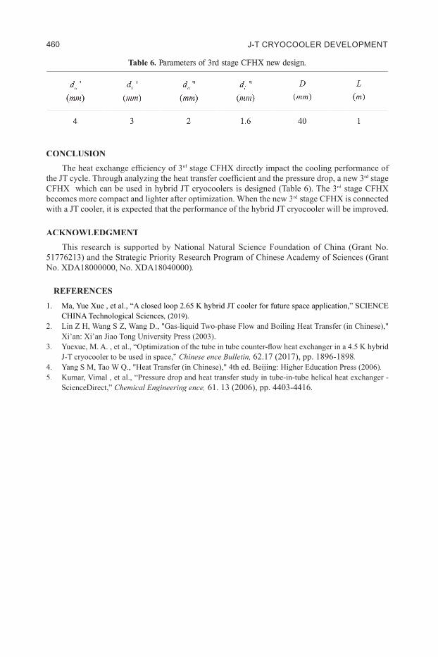
CONCL USIONThe heat exchange efficiency of 3rd stage CFHX directly impact the cooling performance of rd stage CFHX directly impact the cooling performance of rd
the JT cycle. Through analyzing the heat transfer coefficient and the pressure drop, a new 3rd stage rd stage rd
CFHX which can be used in hybrid JT cryocoolers is designed (Table 6). The 3rd stage CFHX rd stage CFHX rd
becomes more compact and lighter after optimization. When the new 3rd stage CFHX is connected rd stage CFHX is connected rd
with a JT cooler, it is expected that the performance of the hybrid JT cryocooler will be improved.
ACKNOW L E DG ME NTThis research is supported by National Natural Science Foundation of China (Grant No.
51776213) and the Strategic Priority Research Program of Chinese Academy of Sciences (Grant No. XDA18000000, No. XDA18040000).
RE F E RE NCE S
1. Ma, Yue Xue , et al., “A closed loop 2.65 K hybrid JT cooler for future space application,” SCIENCE CHINA Technological Sciences, (2019 ).
2. Lin Z H, Wang S Z, Wang D., "Gas-liquid Two-phase Flow and Boiling Heat Transfer (in Chinese)," Xi’an: Xi’an Jiao Tong University Press (2003).
3. Yuexue, M. A. , et al., “Optimization of the tube in tube counter-flow heat exchanger in a 4.5 K hybrid J-T cryocooler to be used in space,” Ch inese ence B u llet in, 62.17 (2017), pp. 1896-1898.
4. Yang S M, Tao W Q., "Heat Transfer (in Chinese)," 4th ed. Beijing: Higher Education Press (2006).5. Kumar, Vimal , et al., “Pressure drop and heat transfer study in tube-in-tube helical heat exchanger -
ScienceDirect,” Ch em ical Engineering ence, 61. 13 (2006), pp. 4403-4416.
Tab l e 6. Parameters of 3rd stage CFHX new design.C21_128 1
Experimental Research on Resonance Characteristics of a High- fficiency Moving Coil Linear Compressor for J-T Throttle Refrigerator
J . Sun1,2, J . L i1, Y. L iu1,2, Z . Huang1,2, N. W ang1, J . Cai1,2
1Key L aboratory of Technology on Space Energy Conversion, Technical Institute of Physics and Chemistry, Chinese Academy of Science, B eijing 10019 0, China2University of Chinese Academy of Sciences, B eijing 100049 , China
ABSTRACTIn order to study the mass flow rate, efficiency and dynamic response characteristics of a linear
compressor for a J-T throttle refrigerator, an online test system was set up to monitor the important dynamic response parameters. The performance and dynamic response characteristics at different driving frequencies were tested under the conditions of fill pressure of 0.7 MPa, pressure ratio of 3 and stroke of 10 mm. At the resonant frequency (65 Hz), motor efficiency, volume efficiency, isen-tropic efficiency and isothermal efficiency have the maximum value, which are respectively 86.7%, 76.5%, 64.1% and 54.5%. A mass flow rate of 0.84 gr/s, and corresponding input power of 151 W. The current waveform has non-sinusoidal distortion, and its bimodal phenomenon on the positive half axis reveals the essential reason for high efficiency at resonance frequency. In addition, the nonlinear distortion law of current waveform can be used to quickly and visually judge whether the linear compressor is resonant in the experiment. In addition, piston offset, opening and closing of the discharge valve, and power loss during suction and discharge process were also studied. The study is very important to analyze the operating state of the linear compressor, judge the matching of the gas valve assembly and optimize the linear compressor.
INTRODUCTIONBecause of the advantages of high efficiency, low vibration, stable operation and strong electromag-
netic resistance, J-T throttling refrigerators have been successfully used in space such as: James Webb Space Telescope (NASA) 1-3, Astro-H and SPICA space exploration mission (JAXA/ESA/NASA)4-6. As the core component of the J-T throttling refrigerator, the efficiency of the linear compressor plays an important role in the total efficiency of the throttling refrigerator7. As we know, the linear compressor has the highest efficiency at resonance frequency, so the research on resonance characteristics of the linear compressor has always been a hot spot. Some work has been carried out to study the flow rate and efficiency characteristics of linear compressor at resonance and non-resonance8. Other work has been done to study how to accurately calculate the value of resonance frequency, such as the average gas force method and the gas force Fourier eq uivalent method9 -10; and some work has been implemented to study the response characteristics of current, displacement and gas force at resonance freq uency11.
E
J -T CRYOCOOLER DEVELOPMENT460


![Cost-based design optimization of the heat exchangers in a ...heat exchangers. A qualitative analysis of the Stream Analysis method is presented by Palen and Taborek [19]. Since, the](https://img.pdfslide.us/doc/110x75/60a1e2355f611c7acf411df6/cost-based-design-optimization-of-the-heat-exchangers-in-a-heat-exchangers.jpg)