Embed Size (px)
Citation preview
Optimization of Synthetic Oxygenated Fuels for Diesel Engines
Investigators Craig. T. Bowman, David M. Golden, Ronald K. Hanson and Heinz Pitsch, Professors David F. Davidson, Senior Research Scientist Adela Bardos, Rob Cook, Zekai Hong, Perrine Pepiot-Desjardins, Syran Ranganath, Shashank, and Kevin Walters, Graduate Researchers Department of Mechanical Engineering Stanford University Ripudaman Malhotra, Research Scientist SRI International André Boehman, Professor Steve Kirby, Research Associate Pennsylvania State University Abstract
Under this project, a systematic and fundamental experimental study of combustion and soot production of various oxygenated molecules was carried out using oxygenates from the main functional families: ethers, esters, aldehydes, alcohols and ketones. The experimental studies provide data on ignition delay, soot yields and soot induction times, and detailed species evolution profiles for the fuel and major intermediate and product species. The results from the experimental studies have been compared with predictions from detailed reaction mechanisms and areas where mechanism improvements are required were identified.
To assess the effectiveness of oxygenated fuels in reducing pollutant emissions in
Diesel engines and to optimize the Diesel engine process for the particular fuel characteristics, a limited set of engine experiments was carried out and methods for three-dimensional numerical simulations of Diesel engine combustion were developed. The simulations permit a more extensive investigation of effects of engine design and operating conditions on performance and emissions. For the simulations, we are developing a state-of-the-art computational tool which is capable of performing Large Eddy Simulation (LES) of turbulent combustion in Diesel engines. The code has been validated by comparison of code predictions with available experimental data on unsteady flows. Introduction
The objectives of this project are to develop novel oxygenated fuels and to establish the chemical kinetic models required to design next-generation combustion engines that run on these fuels. To achieve these objectives, a combined experimental, modeling and computational study is being carried out.
Background
The transportation sector contributes approximately one-third of the total greenhouse gas (GHG) emissions in the United States. Reduction of these emissions in any significant amount will have important impact on the total environmental GHG load.
Various pathways, including improvements in the efficiency of overall vehicle/fuel systems, such as hybrid and new high-efficiency diesel engines, and use of alternative fuels to replace or supplement petroleum-based fuels, have been proposed to achieve these reductions.
A strategy which addresses both of these pathways is the use of oxygenated
compounds for fuels. There are a variety of possible feedstocks that can be used for synthesizing these oxygenates, including petroleum, oil sands, Fisher-Tropsch liquids, biomass, and algae, with the last two of these being approximately carbon neutral for the environment. These oxygenates are also especially attractive for use in the next generation of advanced diesel engines and diesel-hybrids because of the inherently high thermal efficiencies of these engines compared to spark ignition engines and because the molecular structure of oxygenates results in high cetane numbers. In addition, these oxygenates offer significant potential for reduction in particulate (soot) and NOx emissions from diesel engines. The current strict regulations on these emissions have proved to be an impediment to broad introduction of diesel engines into the automotive and light truck sector in the United States. Hence, the use of oxygenates as fuels offers the prospects of reductions in GHG emissions owing to efficiency gains from advanced (i.e., low- or non-sooting) diesel engine concepts.
Critical to the development of new fuels (and the continued use of current fuels) is
concern about the effects of ultra-fine soot particles and associated volatile components. There are significant epidemiological and toxicological studies that link cardio-respiratory health effects with exposures to ultrafine soot particles (diameter < 0.1 µm). The primary sources of these particles are motor vehicles in urban environments. Current soot mitigation methods remove large non-volatile soot particles, but not the precursors of the smaller semi-volatile particles which potentially can have large health risks. The development of cleaner, non-sooting fuels and an understanding of the chemical mechanisms which control this non-sooting behavior are urgently needed to address these risks. Results Approach
To meet program objectives, an experimental study of the combustion and emissions characteristics of oxygenated hydrocarbon fuel molecules is being carried out. An initial study focused on determining in a systematic way the impact of oxygen content and functionality on sooting tendencies of a variety of oxygenates to guide the selection of compounds to be studied in detail. The studies are being conducted in two experimental facilities that have the capability of accessing conditions (temperature and pressure) relevant to diesel engine combustion: a high-pressure shock tube (HPST) and a high-pressure flow reactor (HPFR). These two facilities are complementary in that they can access overlapping regimes of temperature and pressure, but provide different experimental data.
Concurrent with the experimental studies, detailed chemical models have been assembled to establish the role of fuel structure in ignition and NOx and soot formation for a range of temperatures and pressures relevant to diesel engine combustion.
To extrapolate the fundamental data from the experimental and modeling studies to
engines, it is necessary to consider the complex combustion environment of a diesel engine, which is governed by liquid fuel injection and evaporation, swirling flow, complex geometry and the presence of walls. Furthermore, it is necessary to consider a wide range of operating conditions in any optimization process. Hence, the detailed chemical models from the above studies will be applied in three-dimensional numerical simulations of diesel engine combustion using state-of-the-art methods that allow for the consideration of detailed chemistry. The combination of experiments and simulation will allow us to study and understand how oxygenated fuels reduce soot emissions in diesel engines, both at a general and at a very detailed level that will guide the design of optimized fuel structures.
Smoke Point Test Oxygenate Screening Study
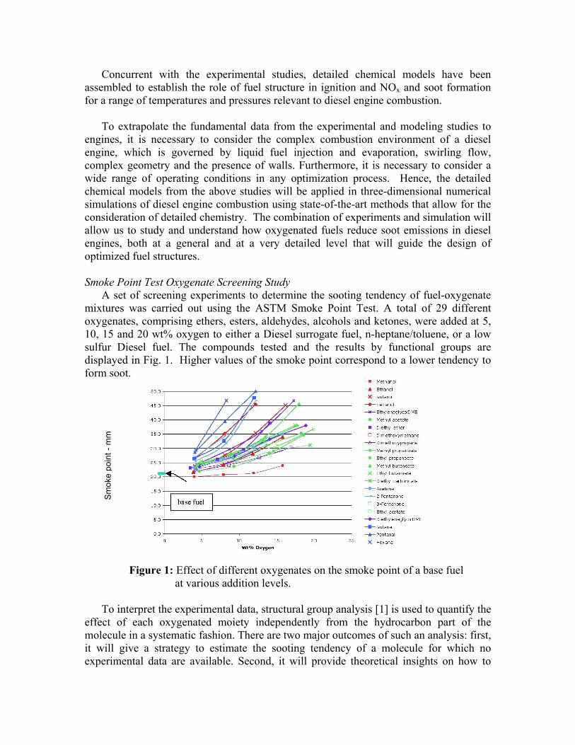
A set of screening experiments to determine the sooting tendency of fuel-oxygenate mixtures was carried out using the ASTM Smoke Point Test. A total of 29 different oxygenates, comprising ethers, esters, aldehydes, alcohols and ketones, were added at 5, 10, 15 and 20 wt% oxygen to either a Diesel surrogate fuel, n-heptane/toluene, or a low sulfur Diesel fuel. The compounds tested and the results by functional groups are displayed in Fig. 1. Higher values of the smoke point correspond to a lower tendency to form soot.
Figure 1: Effect of different oxygenates on the smoke point of a base fuel at various addition levels. To interpret the experimental data, structural group analysis [1] is used to quantify the
effect of each oxygenated moiety independently from the hydrocarbon part of the molecule in a systematic fashion. There are two major outcomes of such an analysis: first, it will give a strategy to estimate the sooting tendency of a molecule for which no experimental data are available. Second, it will provide theoretical insights on how to
Sm
oke
poin
t - m
m

combine hydrocarbon structures and oxygen moieties in a molecule to get the largest reduction in sooting tendency.
The smoke point measurements are first converted to a more convenient, apparatus-
independent quantity, the threshold sooting index, or TSI. TSI is defined as a linear function of the molecular weight (MW in g/mol) of a molecule divided by its smoke point (SP in mm):
where the constants a and b are fit over a large number of experimental data from various sources. A desirable property of TSI over smoke point is the simple, yet efficient mixing rule proposed by Gill and Olson. [2] to obtain the TSI of a mixture:
where X
k and TSI
k are, respectively, the mole fraction and TSI of component k in the
mixture.
Figure 2 shows the experimental TSIs versus the simulated TSI using a linear mixing rule. The correlation coefficient is nearly 99%, the maximum error is 14.6% while the average error is only 4.15%. Good correlations are obtained regardless of the type of base fuel. The lowest TSI values are obtained with the heptane/toluene base fuel; the highest values are obtained with Diesel fuel.
Figure 2: Correlation between experimental and simulated TSIs
The structural analysis of the TSI measurements allows a precise estimate of the
efficiency of the different oxygenated functional groups. It also permits simulation of the effect of molecules different from the list of molecules screened experimentally that can be constructed from groups for which a contribution was determined.
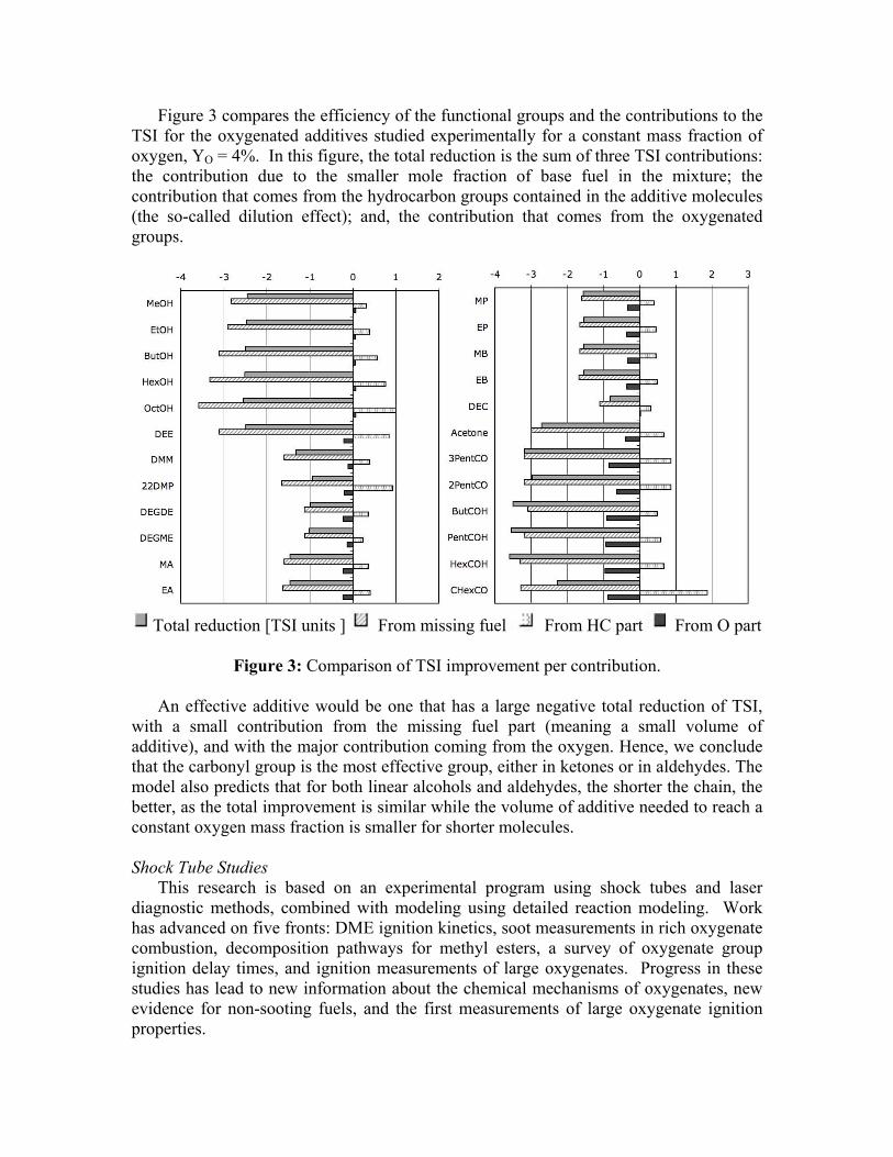
Figure 3 compares the efficiency of the functional groups and the contributions to the TSI for the oxygenated additives studied experimentally for a constant mass fraction of oxygen, YO = 4%. In this figure, the total reduction is the sum of three TSI contributions: the contribution due to the smaller mole fraction of base fuel in the mixture; the contribution that comes from the hydrocarbon groups contained in the additive molecules (the so-called dilution effect); and, the contribution that comes from the oxygenated groups.
Total reduction [TSI units ] From missing fuel From HC part From O part
Figure 3: Comparison of TSI improvement per contribution.
An effective additive would be one that has a large negative total reduction of TSI,
with a small contribution from the missing fuel part (meaning a small volume of additive), and with the major contribution coming from the oxygen. Hence, we conclude that the carbonyl group is the most effective group, either in ketones or in aldehydes. The model also predicts that for both linear alcohols and aldehydes, the shorter the chain, the better, as the total improvement is similar while the volume of additive needed to reach a constant oxygen mass fraction is smaller for shorter molecules.
Shock Tube Studies
This research is based on an experimental program using shock tubes and laser diagnostic methods, combined with modeling using detailed reaction modeling. Work has advanced on five fronts: DME ignition kinetics, soot measurements in rich oxygenate combustion, decomposition pathways for methyl esters, a survey of oxygenate group ignition delay times, and ignition measurements of large oxygenates. Progress in these studies has lead to new information about the chemical mechanisms of oxygenates, new evidence for non-sooting fuels, and the first measurements of large oxygenate ignition properties.
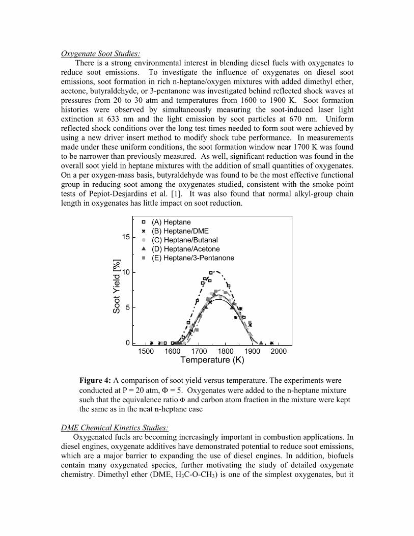
Oxygenate Soot Studies: There is a strong environmental interest in blending diesel fuels with oxygenates to
reduce soot emissions. To investigate the influence of oxygenates on diesel soot emissions, soot formation in rich n-heptane/oxygen mixtures with added dimethyl ether, acetone, butyraldehyde, or 3-pentanone was investigated behind reflected shock waves at pressures from 20 to 30 atm and temperatures from 1600 to 1900 K. Soot formation histories were observed by simultaneously measuring the soot-induced laser light extinction at 633 nm and the light emission by soot particles at 670 nm. Uniform reflected shock conditions over the long test times needed to form soot were achieved by using a new driver insert method to modify shock tube performance. In measurements made under these uniform conditions, the soot formation window near 1700 K was found to be narrower than previously measured. As well, significant reduction was found in the overall soot yield in heptane mixtures with the addition of small quantities of oxygenates. On a per oxygen-mass basis, butyraldehyde was found to be the most effective functional group in reducing soot among the oxygenates studied, consistent with the smoke point tests of Pepiot-Desjardins et al. [1]. It was also found that normal alkyl-group chain length in oxygenates has little impact on soot reduction.
1500 1600 1700 1800 1900 20000
5
10
15
Soot
Yie
ld [%
]
Temperature (K)
(A) Heptane(B) Heptane/DME(C) Heptane/Butanal(D) Heptane/Acetone(E) Heptane/3-Pentanone
Figure 4: A comparison of soot yield versus temperature. The experiments were
conducted at P = 20 atm, Φ = 5. Oxygenates were added to the n-heptane mixture such that the equivalence ratio Φ and carbon atom fraction in the mixture were kept the same as in the neat n-heptane case
DME Chemical Kinetics Studies:
Oxygenated fuels are becoming increasingly important in combustion applications. In diesel engines, oxygenate additives have demonstrated potential to reduce soot emissions, which are a major barrier to expanding the use of diesel engines. In addition, biofuels contain many oxygenated species, further motivating the study of detailed oxygenate chemistry. Dimethyl ether (DME, H3C-O-CH3) is one of the simplest oxygenates, but it
has a limited experimental and modeling database. Ignition delay times were measured in DME/O2/Ar mixtures behind reflected shock waves. Initial reflected shock conditions covered temperatures from 1175 – 1900 K, pressures from 1.6 – 6.6 bar, and equivalence ratios from 0.5 – 3.0. Ignition delay times were measured by collecting OH* emission near 307 nm. The ignition delay times extended the experimental database of DME to a greater range of equivalence ratios and pressures. Measured ignition delay times were compared to simulations based on DME oxidation mechanisms by Fischer et al. [3] and Zhao et al. [4]. Both mechanisms predict the magnitude of ignition delay times well.
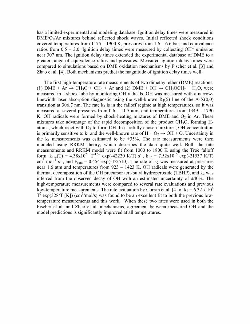
The first high-temperature rate measurements of two dimethyl ether (DME) reactions, (1) DME + Ar → CH3O + CH3 + Ar and (2) DME + OH → CH3OCH2 + H2O, were measured in a shock tube by monitoring OH radicals. OH was measured with a narrow-linewidth laser absorption diagnostic using the well-known R1(5) line of the A-X(0,0) transition at 306.7 nm. The rate k1 is in the falloff regime at high temperatures, so it was measured at several pressures from 0.6 – 11.5 atm, and temperatures from 1349 – 1790 K. OH radicals were formed by shock-heating mixtures of DME and O2 in Ar. These mixtures take advantage of the rapid decomposition of the product CH3O, forming H-atoms, which react with O2 to form OH. In carefully chosen mixtures, OH concentration is primarily sensitive to k1 and the well-known rate of H + O2 → OH + O. Uncertainty in the k1 measurements was estimated to be ±35%. The rate measurements were then modeled using RRKM theory, which describes the data quite well. Both the rate measurements and RRKM model were fit from 1000 to 1800 K using the Troe falloff form: k1,∞(T) = 4.38x10²¹ T-1.57 exp(-42220 K/T) s-1, k1,o = 7.52x10¹⁵ exp(-21537 K/T) cm3 mol-1 s-1, and Fcent = 0.454 exp(-T/2510). The rate of k2 was measured at pressures near 1.6 atm and temperatures from 923 – 1423 K. OH radicals were generated by the thermal decomposition of the OH precursor tert-butyl hydroperoxide (TBHP), and k2 was inferred from the observed decay of OH with an estimated uncertainty of ±40%. The high-temperature measurements were compared to several rate evaluations and previous low-temperature measurements. The rate evaluation by Curran et al. [4] of k2 = 6.32 x 10⁶ T2
exp(328/T [K]) (cm3/mol/s) was found to be an excellent fit to both the previous low-temperature measurements and this work. When these two rates were used in both the Fischer et al. and Zhao et al. mechanisms, agreement between measured OH and the model predictions is significantly improved at all temperatures.
0.5 0.6 0.7 0.8 0.9101
102
103
104
105
1667 1429 1250 11112000 K
Stanford data, P=1.5atm RRKM model, P=1.5 atm Curran et al. [7] Zhao et al. [8] Dagaut et al. [10] Hidaka et al. [11]
k 1 [1/
s]
1000/T [1/T] 0.5 1.0 1.5 2.0 2.5 3.0 3.5
1012
1013
667 500 400 333 28610002000 K
Stanford data Curran et al. [7] Zhao et al. [8] Dagaut et al. [10] Bonard et al. [17] Arif et al. [16] Perry et al. [12] Wallington et al. [13] Tully et al. [14] Mellouki et al. [15]
k 2 [cm
3 mol
-1s-1
]
1000/T [1/K]
Figure 5a (left): Comparison of measured k1 rate and RRKM model (current study) to previous rate calculations and fit to shock tube pyrolysis data at P = 1.5 atm. Figure 5b (right): Comparison of measured high-temperature k2 rate to rates used in DME mechanisms (lines), low-temperature LIF measurements (solid symbols), and low-temperature fluorescence measurements (open symbols).
High Temperature Methyl Ester Decomposition Chemistry:
The use of bio-diesel fuels as replacements or supplements for crude-oil-derived diesel fuel addresses two of the major concerns about current diesel supplies, namely greenhouse gas emissions and sulfur content. Bio-diesel offers the advantage of a renewable fuel with little added atmospheric CO2 greenhouse burden and the advantage of a clean fuel with a low potential to form SOx. It has also been shown that bio-diesel fueled engines can produce less CO and unburned hydrocarbons particularly when compared to diesel fuel. Derivable from vegetable oils and animal fats, bio-diesels usually take the form of long-chain methyl esters. High-temperature shock tube studies of methyl ester pyrolysis and oxidation can provide kinetic targets needed to refine and validate detailed mechanisms for these fuels.
These long-chain methyl esters, while directly compatible with diesel operation, are
generally difficult to study in the laboratory because of their low vapor pressure and chemical complexity. Methyl butanoate, CH3CH2CH2CO2CH3 (MB) has been used as a surrogate for long-chain methyl esters by several researchers because it contains much of the essential chemical structure of its long-chain counterparts, i.e., the methyl ester termination and a shorter, but similar alkyl chain, and because detailed reaction mechanisms describing this fuel are of a manageable size.
The high temperature decomposition of three simple methyl esters: methyl acetate, methyl propionate and methyl butanoate, were studied behind reflected shock waves using tunable diode laser absorption of CO2 near 2.7 μm. CO2 yield measurements were made over a range of temperatures of 1260-1653 K, pressures of 1.4-1.7 atm and reactant concentrations of 2-3 %, with the balance Ar. The CO2 absorption strengths near 2.7 μm are approximately 50 to 1000 times stronger than the bands near 2.0 μm and 1.55 μm, respectively, and offer opportunities for significantly more sensitive and accurate

combustion measurements than previous absorption work using CO2 bands at shorter wavelength. The experiments provide the first laser-based time-history measurements of the CO2 yields during pyrolysis of these bio-diesel surrogate fuels in a shock tube. Model predictions for CO2 yields during methyl butanoate pyrolysis at high temperatures, using the detailed reaction mechanisms of Fisher et al. [3] and others, are significantly lower than those measured in this study. However, an improved methyl butanoate model which extends the recent theoretical work of Huynh and Violi [6] provides substantially improved predictions of CO2 yields during methyl butanoate pyrolysis. As earlier mechanisms predicted low yields of CO2 from methyl butanoate decomposition, these new findings imply that existing bio-diesel fuel models, which rely on the rapid formation of two oxygenate radicals from methyl esters (rather than a single non-reactive CO2 molecule) to account for the tendency for soot reduction, may have to be revisited.
0.0 0.2 0.4 0.6 0.8 1.0
0.0
0.2
0.4
0.6
0.8
1.0
1.2
1.4
1653 K, 1.45 atm
1512 K, 1.48 atm
1426 K, 1.58 atm
1260 K, 1.70 atm
CO
2 Mol
e Fr
actio
n [%
]
Time [ms]
2% MB/Ar
1341 K, 1.63 atm
Figure 6: Calculated (light solid) and measured (heavy solid) CO2 concentration time histories for methyl butanoate pyrolysis (2% MB in Ar). CO2 profiles were calculated using the improved MB model of the current study.
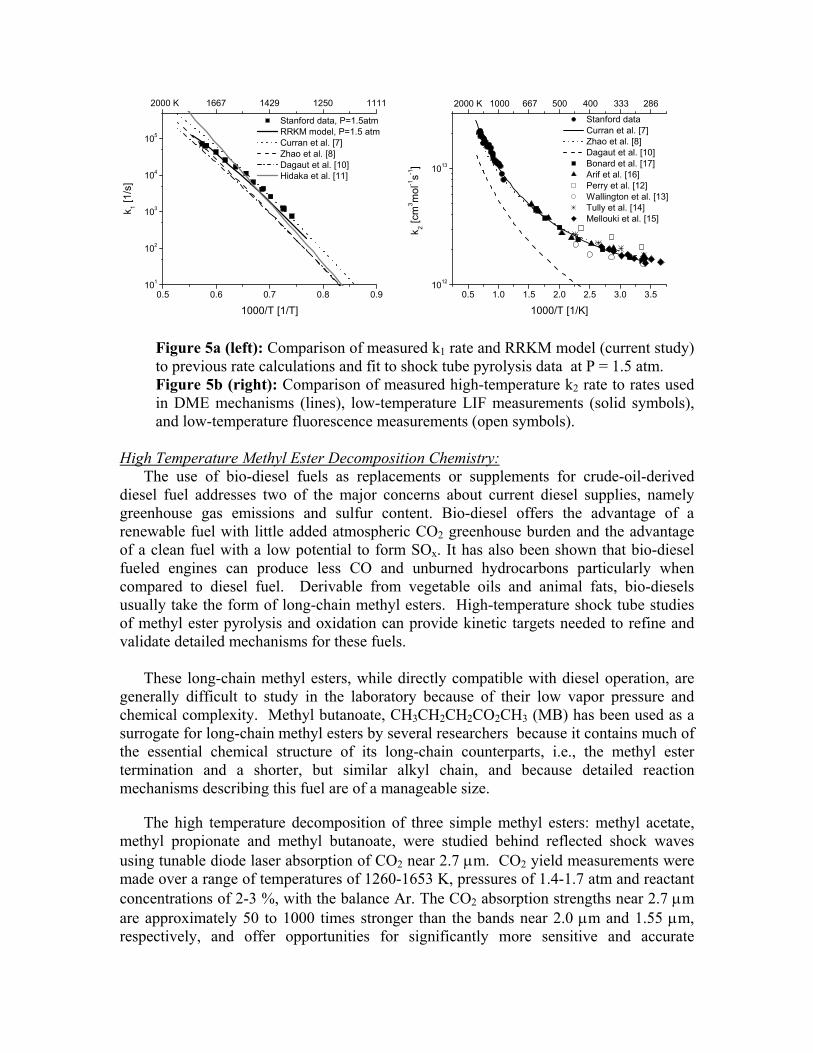
Survey of Oxygenate Ignition Times:
Ignition delay time data for oxygen-carrying species are required for the development and refinement of oxygenate fuel mechanisms. To fill this need, ignition delay times were measured using pressure and OH* emission diagnostics behind reflected shock waves for several simple oxygenates. Reflected shock conditions covered temperatures of 1150-1550 K and pressures of 1-4 atm. Fuel mixtures tested include the four oxygenates: acetone, n-butanal, methyl butanoate, and 3-pentanone. All fuels were tested in O2/argon mixtures with equivalence ratios of 0.5 to 2.0. A new n-butanal reaction mechanism (based on the Dooley et al. (2009) [6] mechanism for methyl butanoate) was used to model the n-butanal and methyl butanoate data.
0.60 0.65 0.70 0.75 0.80 0.85 0.90
100
1000
100001176K
1.7 atm, 4% O2/Ar, φ=1 3-pentanone butanal methyl butanoate acetone n-pentane
Igni
tion
Del
ay T
ime
[μs]
1000/T [1/K]
1538K
Figure 7: Arrhenius plot of oxygenate species ignition delay times: φ = 1.0.
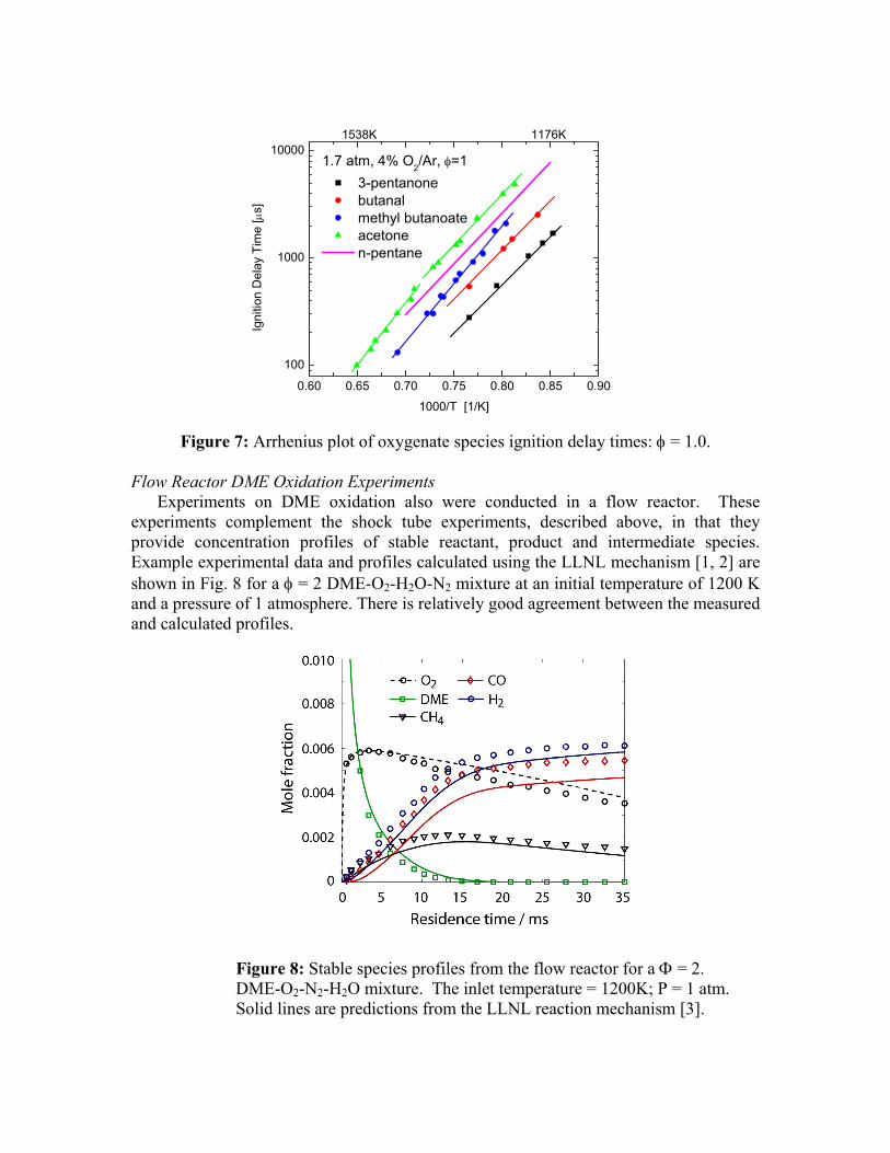
Flow Reactor DME Oxidation Experiments
Experiments on DME oxidation also were conducted in a flow reactor. These experiments complement the shock tube experiments, described above, in that they provide concentration profiles of stable reactant, product and intermediate species. Example experimental data and profiles calculated using the LLNL mechanism [1, 2] are shown in Fig. 8 for a φ = 2 DME-O2-H2O-N2 mixture at an initial temperature of 1200 K and a pressure of 1 atmosphere. There is relatively good agreement between the measured and calculated profiles.
Figure 8: Stable species profiles from the flow reactor for a Φ = 2. DME-O2-N2-H2O mixture. The inlet temperature = 1200K; P = 1 atm. Solid lines are predictions from the LLNL reaction mechanism [3].
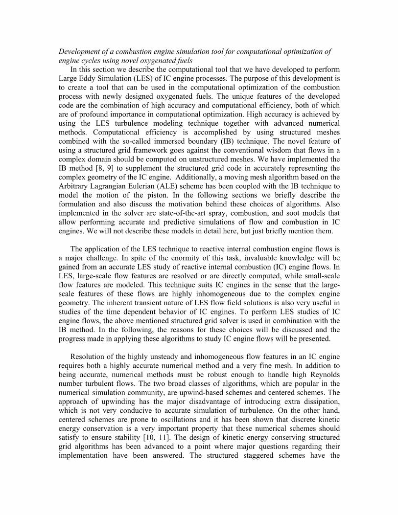
Development of a combustion engine simulation tool for computational optimization of engine cycles using novel oxygenated fuels
In this section we describe the computational tool that we have developed to perform Large Eddy Simulation (LES) of IC engine processes. The purpose of this development is to create a tool that can be used in the computational optimization of the combustion process with newly designed oxygenated fuels. The unique features of the developed code are the combination of high accuracy and computational efficiency, both of which are of profound importance in computational optimization. High accuracy is achieved by using the LES turbulence modeling technique together with advanced numerical methods. Computational efficiency is accomplished by using structured meshes combined with the so-called immersed boundary (IB) technique. The novel feature of using a structured grid framework goes against the conventional wisdom that flows in a complex domain should be computed on unstructured meshes. We have implemented the IB method [8, 9] to supplement the structured grid code in accurately representing the complex geometry of the IC engine. Additionally, a moving mesh algorithm based on the Arbitrary Lagrangian Eulerian (ALE) scheme has been coupled with the IB technique to model the motion of the piston. In the following sections we briefly describe the formulation and also discuss the motivation behind these choices of algorithms. Also implemented in the solver are state-of-the-art spray, combustion, and soot models that allow performing accurate and predictive simulations of flow and combustion in IC engines. We will not describe these models in detail here, but just briefly mention them.
The application of the LES technique to reactive internal combustion engine flows is
a major challenge. In spite of the enormity of this task, invaluable knowledge will be gained from an accurate LES study of reactive internal combustion (IC) engine flows. In LES, large-scale flow features are resolved or are directly computed, while small-scale flow features are modeled. This technique suits IC engines in the sense that the large-scale features of these flows are highly inhomogeneous due to the complex engine geometry. The inherent transient nature of LES flow field solutions is also very useful in studies of the time dependent behavior of IC engines. To perform LES studies of IC engine flows, the above mentioned structured grid solver is used in combination with the IB method. In the following, the reasons for these choices will be discussed and the progress made in applying these algorithms to study IC engine flows will be presented.
Resolution of the highly unsteady and inhomogeneous flow features in an IC engine
requires both a highly accurate numerical method and a very fine mesh. In addition to being accurate, numerical methods must be robust enough to handle high Reynolds number turbulent flows. The two broad classes of algorithms, which are popular in the numerical simulation community, are upwind-based schemes and centered schemes. The approach of upwinding has the major disadvantage of introducing extra dissipation, which is not very conducive to accurate simulation of turbulence. On the other hand, centered schemes are prone to oscillations and it has been shown that discrete kinetic energy conservation is a very important property that these numerical schemes should satisfy to ensure stability [10, 11]. The design of kinetic energy conserving structured grid algorithms has been advanced to a point where major questions regarding their implementation have been answered. The structured staggered schemes have the
advantage of being discretely kinetic energy conserving, very accurate, and extremely fast.
One of the obvious disadvantages of a structured grid solver as compared to an
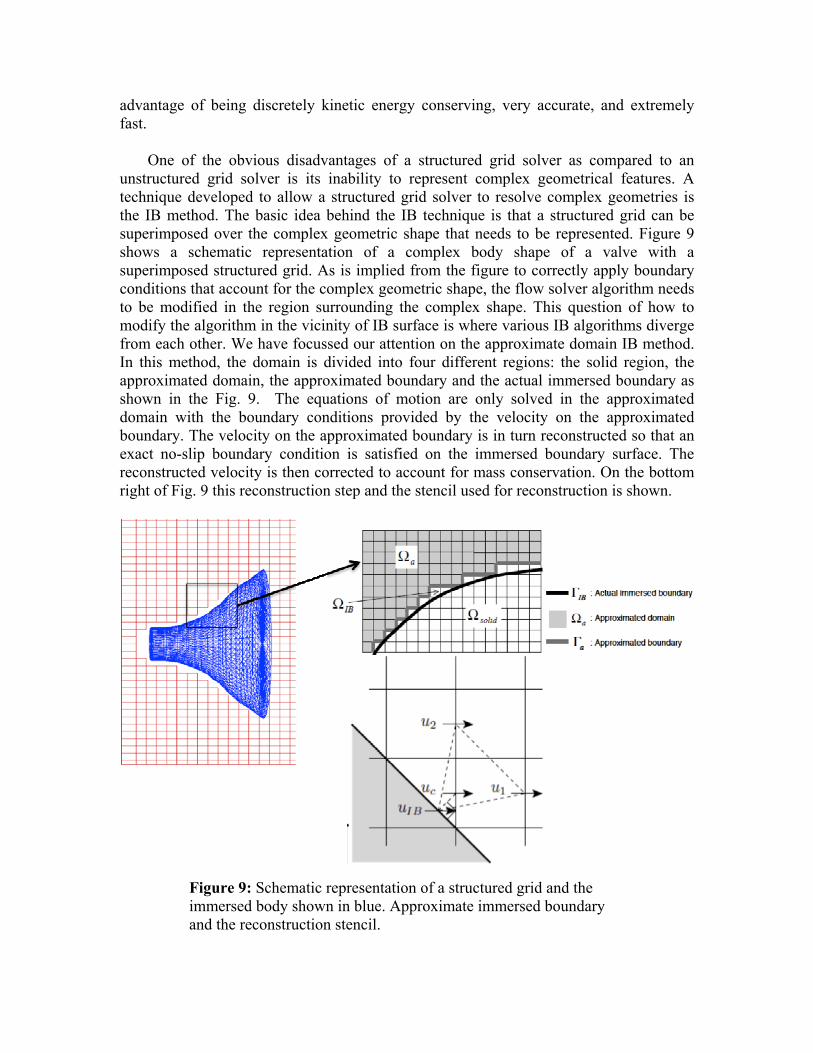
unstructured grid solver is its inability to represent complex geometrical features. A technique developed to allow a structured grid solver to resolve complex geometries is the IB method. The basic idea behind the IB technique is that a structured grid can be superimposed over the complex geometric shape that needs to be represented. Figure 9 shows a schematic representation of a complex body shape of a valve with a superimposed structured grid. As is implied from the figure to correctly apply boundary conditions that account for the complex geometric shape, the flow solver algorithm needs to be modified in the region surrounding the complex shape. This question of how to modify the algorithm in the vicinity of IB surface is where various IB algorithms diverge from each other. We have focussed our attention on the approximate domain IB method. In this method, the domain is divided into four different regions: the solid region, the approximated domain, the approximated boundary and the actual immersed boundary as shown in the Fig. 9. The equations of motion are only solved in the approximated domain with the boundary conditions provided by the velocity on the approximated boundary. The velocity on the approximated boundary is in turn reconstructed so that an exact no-slip boundary condition is satisfied on the immersed boundary surface. The reconstructed velocity is then corrected to account for mass conservation. On the bottom right of Fig. 9 this reconstruction step and the stencil used for reconstruction is shown.
Figure 9: Schematic representation of a structured grid and the immersed body shown in blue. Approximate immersed boundary and the reconstruction stencil.
One of the major disadvantages of an unstructured grid solver or body conforming structured grid solver is the highly cumbersome and time-consuming process of mesh generation. Using the IB technique described above, this time consuming step is completely sidestepped and the method thus shortens the pre-processing time. Because of this feature, geometric variations of cylinder and piston can also be considered as part of a computational optimization process.
Moreover, a structured grid easily allows for the development of spatially high order accurate finite difference schemes that use the IB technique to represent the complex geometries, for example, the valves and piston bowl geometry. This has the additional advantage that the motion of the valves does not lead to a modification of the mesh. Since the valve motion is complex, moving meshes associated with this motion are often of poor quality. The piston motion, which simply results in a linear motion of the mesh points in one direction, is treated here with a moving mesh technique. The moving mesh technique is based on the Arbitrary Lagrangian Eulerian (ALE) algorithm. In the Eulerian approach, which is usually used in fluid dynamics codes, the grid nodes are stationary. In the Lagrangian approach, often used in solid mechanics codes, the grid nodes move with the material associated with the respective grid nodes. In the ALE method, advantages of both approaches are coupled. In ALE, the grid nodes near the moving boundaries move with the same velocity as the boundaries, whereas the regions where large strain rates are observed, the grid nodes remain stationary as in the Eulerian approach.
In LES, the effect of unresolved scales is modeled using a subgrid-scale (SGS) model. The dynamic Smagorinsky model and the Lagrangian dynamic model, which have shown good potential for inhomogeneous flows, have been implemented in the code. Highly accurate combustion models for both premixed and non-premixed turbulent combustion are available. Models for spray breakup and evaporation have also been implemented in this solver, as well as the state of the art soot models based on the method of moments, which have been shown to perform very accurately, and are computationally inexpensive when compared with the even more accurate Monte-Carlo simulations.
In the following section, some results from LES simulations performed using these
computational methods are presented. All test cases have configurations representative of IC engine geometries and thereby test different aspects of the computational tool. The results from these simulations are compared against experimental data and will help underline the choice of the computational algorithms. Steady flow bench:
Overall engine performance strongly depends on the restriction of inlet and exhaust, which could be from the valve or from valve and port together. Due to the strong recirculating flow, Reynolds averaged Navier-Stokes (RANS) based modeling approaches have been found inadequate for predictions of mass flow rates through the restriction at various valve seat heights. The large-scale flow features are directly resolved in the case of LES, and hence, LES will be very useful in accurate predictions of coefficient of discharge and mass flow rate through the valves. We have performed LES of the flow in steady flow bench experiments [12]. Results from simulations of two
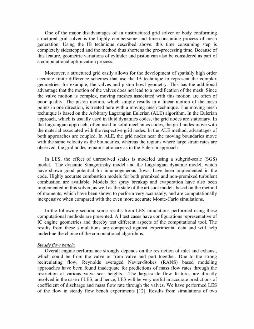
different configurations, one with a simplified cylinder and port arrangement and the other with a complex setting of two valves.
Figure 10: Geometry of the simple valve flow bench. Cross-sectional view.
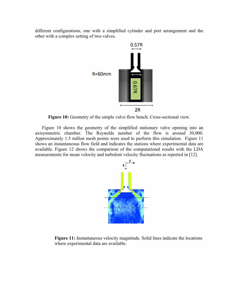
Figure 10 shows the geometry of the simplified stationary valve opening into an
axisymmetric chamber. The Reynolds number of the flow is around 30,000. Approximately 1.5 millon mesh points were used to perform this simulation. Figure 11 shows an instantaneous flow field and indicates the stations where experimental data are available. Figure 12 shows the comparison of the computational results with the LDA measurements for mean velocity and turbulent velocity fluctuations as reported in [12].
Figure 11: Instantaneous velocity magnitude. Solid lines indicate the locations where experimental data are available.

A very good agreement is observed between the experimental measurements and the computational results. The azimuthal turbulent velocity fluctuations, which are usually very small in magnitude and difficult to capture, are very well reproduced in the simulations.
In order to test the new strategy in a much more complex and a realistic setting, the
flow in a steady flow bench experiment with two valves [12] is also computed. Figure 13 shows the 3D geometry as well as a cross-sectional view. It is observed in this figure that the manifold and valve geometry are a very good representation of the actual geometry of an IC engine
Figure 13: Geometry of the steady flow bench experiment. 3D and cross-sectional view.
Figure 12: Velocity comparison between LES (lines) and LDA measurements (symbols).
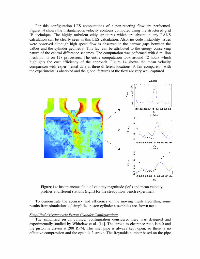
For this configuration LES computations of a non-reacting flow are performed. Figure 14 shows the instantaneous velocity contours computed using the structured grid IB technique. The highly turbulent eddy structures which are absent in any RANS calculation can be clearly seen in this LES calculation. Also, no code instability issues were observed although high speed flow is observed in the narrow gaps between the valbes and the cylinder geometry. This fact can be attributed to the energy conserving nature of the central difference schemes. The computation was peformed with 8 million mesh points on 128 processors. The entire computation took around 12 hours which highlights the cost efficiency of the approach. Figure 14 shows the mean velocity comparison with experimental data at three different locations. A fair comparison with the experiments is observed and the global features of the flow are very well captured.
To demonstrate the accuracy and efficiency of the moving mesh algorithm, some results from simulations of simplified piston cylinder assemblies are shown next. Simplified Axisymmetric Piston Cylinder Configuration:
The simplified piston cylinder configuration considered here was designed and experimentally studied by Whitelaw et al. [14]. The stroke to clearance ratio is 4.0 and the piston is driven at 200 RPM. The inlet pipe is always kept open, so there is no effective compression and the cycle is 2-stroke. The Reynolds number based on the pipe
Figure 14: Instantaneous field of velocity magnitude (left) and mean velocity profiles at different stations (right) for the steady flow bench experiment.
diameter and the inlet velocity corresponding to the maximum piston velocity is around 13,000. This configuration was chosen because it is representative of some of the effects seen in real IC engines.
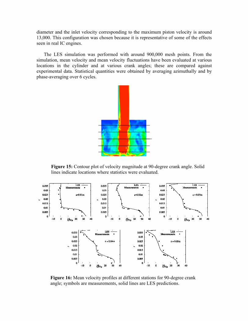
The LES simulation was performed with around 900,000 mesh points. From the
simulation, mean velocity and mean velocity fluctuations have been evaluated at various locations in the cylinder and at various crank angles; these are compared against experimental data. Statistical quantities were obtained by averaging azimuthally and by phase-averaging over 6 cycles.
Figure 15: Contour plot of velocity magnitude at 90-degree crank angle. Solid lines indicate locations where statistics were evaluated.
Figure 16: Mean velocity profiles at different stations for 90-degree crank angle; symbols are measurements, solid lines are LES predictions.
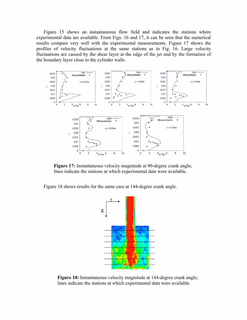
Figure 15 shows an instantaneous flow field and indicates the stations where experimental data are available. From Figs. 16 and 17, it can be seen that the numerical results compare very well with the experimental measurements. Figure 17 shows the profiles of velocity fluctuations at the same stations as in Fig. 16. Large velocity fluctuations are caused by the shear layer at the edge of the jet and by the formation of the boundary layer close to the cylinder walls.
Figure 18 shows results for the same case at 144-degree crank angle.
Figure 17: Instantaneous velocity magnitude at 90-degree crank angle; lines indicate the stations at which experimental data were available.
Figure 18: Instantaneous velocity magnitude at 144-degree crank angle; lines indicate the stations at which experimental data were available.
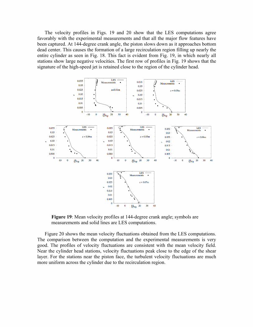
The velocity profiles in Figs. 19 and 20 show that the LES computations agree favorably with the experimental measurements and that all the major flow features have been captured. At 144-degree crank angle, the piston slows down as it approaches bottom dead center. This causes the formation of a large recirculation region filling up nearly the entire cylinder as seen in Fig. 18. This fact is evident from Fig. 19, in which nearly all stations show large negative velocities. The first row of profiles in Fig. 19 shows that the signature of the high-speed jet is retained close to the region of the cylinder head.
Figure 20 shows the mean velocity fluctuations obtained from the LES computations. The comparison between the computation and the experimental measurements is very good. The profiles of velocity fluctuations are consistent with the mean velocity field. Near the cylinder head stations, velocity fluctuations peak close to the edge of the shear layer. For the stations near the piston face, the turbulent velocity fluctuations are much more uniform across the cylinder due to the recirculation region.
Figure 19: Mean velocity profiles at 144-degree crank angle; symbols are measurements and solid lines are LES computations.
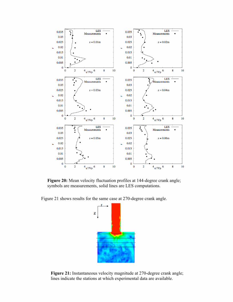
Figure 21 shows results for the same case at 270-degree crank angle.
Figure 20: Mean velocity fluctuation profiles at 144-degree crank angle; symbols are measurements, solid lines are LES computations.
Figure 21: Instantaneous velocity magnitude at 270-degree crank angle; lines indicate the stations at which experimental data are available.
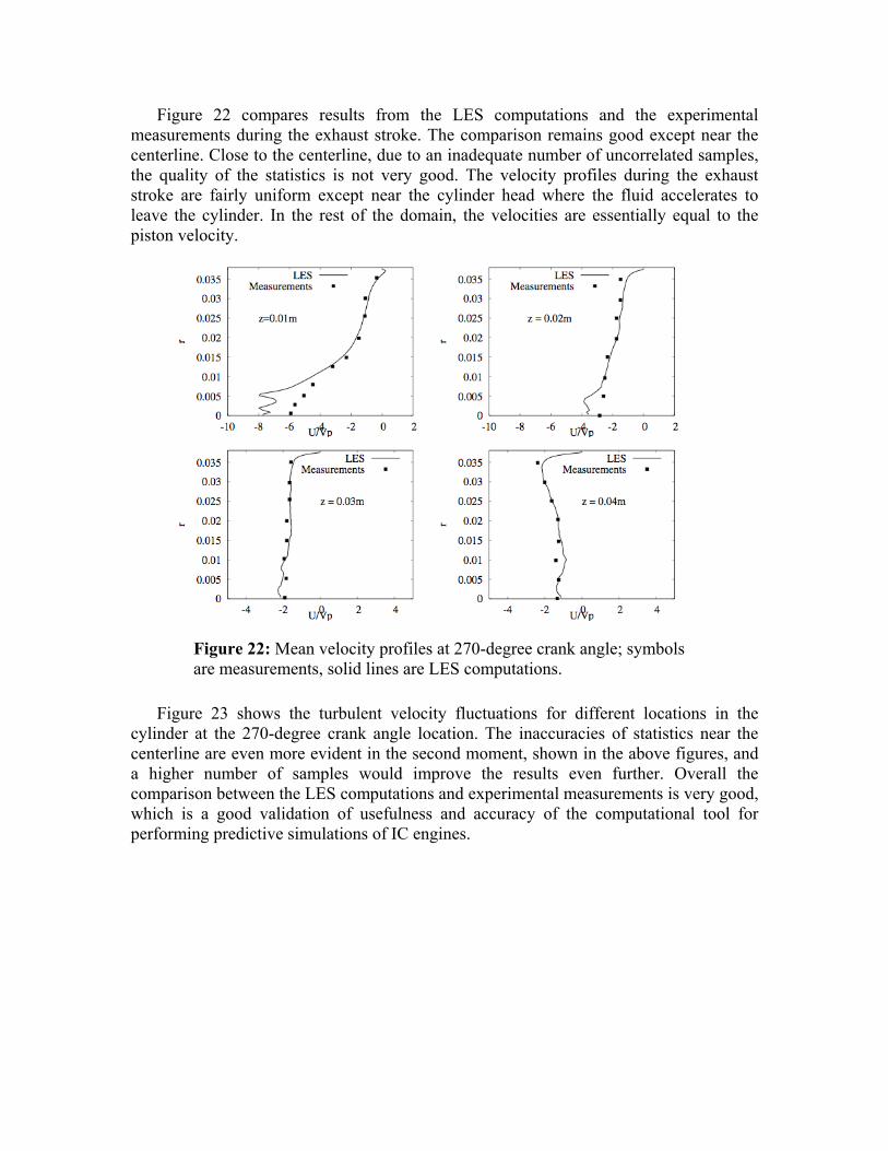
Figure 22 compares results from the LES computations and the experimental measurements during the exhaust stroke. The comparison remains good except near the centerline. Close to the centerline, due to an inadequate number of uncorrelated samples, the quality of the statistics is not very good. The velocity profiles during the exhaust stroke are fairly uniform except near the cylinder head where the fluid accelerates to leave the cylinder. In the rest of the domain, the velocities are essentially equal to the piston velocity.
Figure 23 shows the turbulent velocity fluctuations for different locations in the cylinder at the 270-degree crank angle location. The inaccuracies of statistics near the centerline are even more evident in the second moment, shown in the above figures, and a higher number of samples would improve the results even further. Overall the comparison between the LES computations and experimental measurements is very good, which is a good validation of usefulness and accuracy of the computational tool for performing predictive simulations of IC engines.
Figure 22: Mean velocity profiles at 270-degree crank angle; symbols are measurements, solid lines are LES computations.
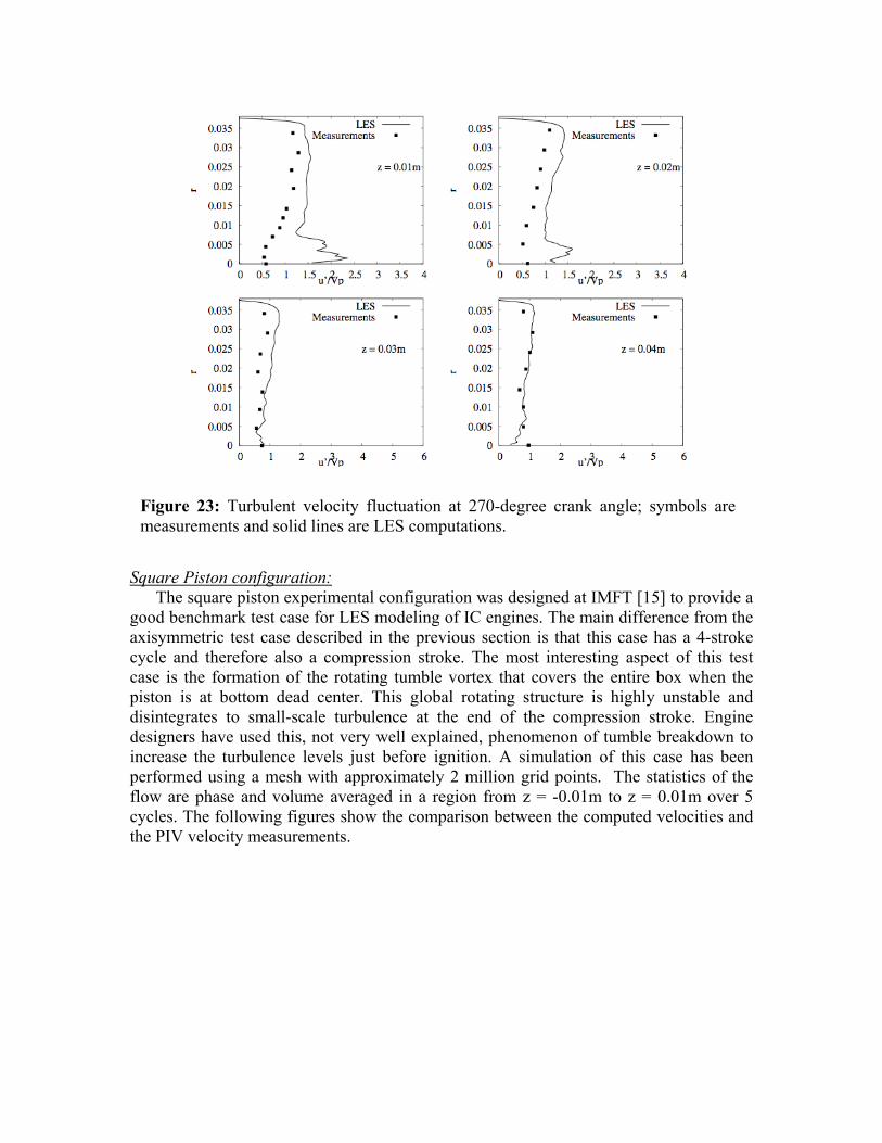
Square Piston configuration: The square piston experimental configuration was designed at IMFT [15] to provide a
good benchmark test case for LES modeling of IC engines. The main difference from the axisymmetric test case described in the previous section is that this case has a 4-stroke cycle and therefore also a compression stroke. The most interesting aspect of this test case is the formation of the rotating tumble vortex that covers the entire box when the piston is at bottom dead center. This global rotating structure is highly unstable and disintegrates to small-scale turbulence at the end of the compression stroke. Engine designers have used this, not very well explained, phenomenon of tumble breakdown to increase the turbulence levels just before ignition. A simulation of this case has been performed using a mesh with approximately 2 million grid points. The statistics of the flow are phase and volume averaged in a region from z = -0.01m to z = 0.01m over 5 cycles. The following figures show the comparison between the computed velocities and the PIV velocity measurements.
Figure 23: Turbulent velocity fluctuation at 270-degree crank angle; symbols are measurements and solid lines are LES computations.
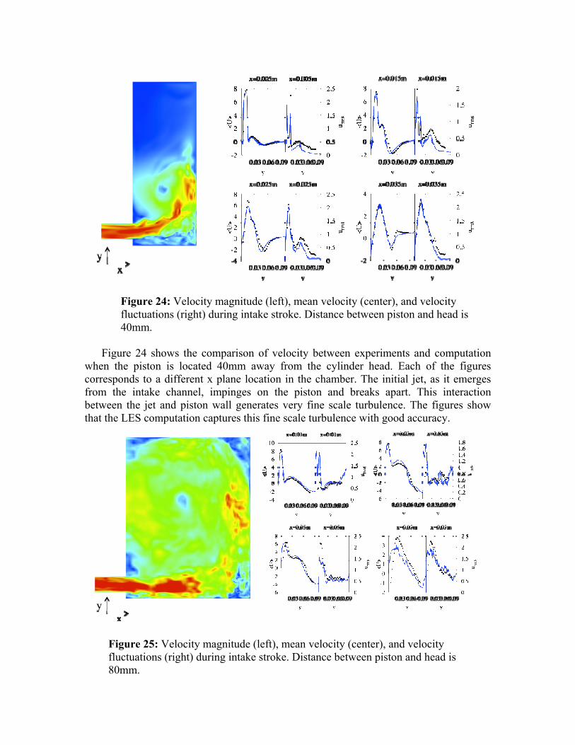
Figure 24 shows the comparison of velocity between experiments and computation when the piston is located 40mm away from the cylinder head. Each of the figures corresponds to a different x plane location in the chamber. The initial jet, as it emerges from the intake channel, impinges on the piston and breaks apart. This interaction between the jet and piston wall generates very fine scale turbulence. The figures show that the LES computation captures this fine scale turbulence with good accuracy.
Figure 24: Velocity magnitude (left), mean velocity (center), and velocity fluctuations (right) during intake stroke. Distance between piston and head is 40mm.
Figure 25: Velocity magnitude (left), mean velocity (center), and velocity fluctuations (right) during intake stroke. Distance between piston and head is 80mm.
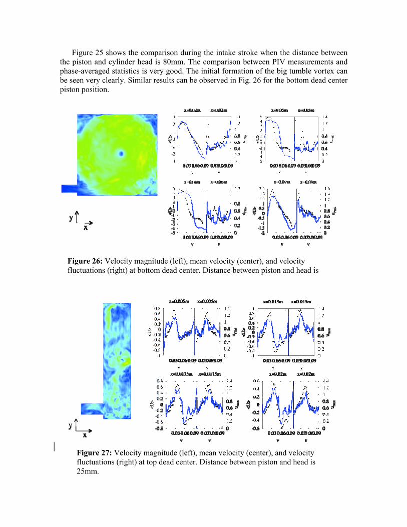
Figure 25 shows the comparison during the intake stroke when the distance between the piston and cylinder head is 80mm. The comparison between PIV measurements and phase-averaged statistics is very good. The initial formation of the big tumble vortex can be seen very clearly. Similar results can be observed in Fig. 26 for the bottom dead center piston position.
Figure 26: Velocity magnitude (left), mean velocity (center), and velocity fluctuations (right) at bottom dead center. Distance between piston and head is 100
Figure 27: Velocity magnitude (left), mean velocity (center), and velocity fluctuations (right) at top dead center. Distance between piston and head is 25mm.
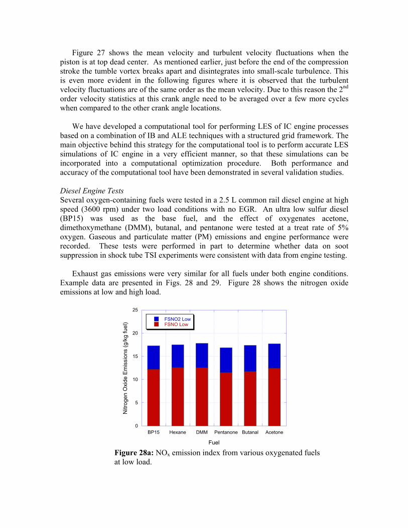
Figure 27 shows the mean velocity and turbulent velocity fluctuations when the piston is at top dead center. As mentioned earlier, just before the end of the compression stroke the tumble vortex breaks apart and disintegrates into small-scale turbulence. This is even more evident in the following figures where it is observed that the turbulent velocity fluctuations are of the same order as the mean velocity. Due to this reason the 2nd order velocity statistics at this crank angle need to be averaged over a few more cycles when compared to the other crank angle locations.
We have developed a computational tool for performing LES of IC engine processes based on a combination of IB and ALE techniques with a structured grid framework. The main objective behind this strategy for the computational tool is to perform accurate LES simulations of IC engine in a very efficient manner, so that these simulations can be incorporated into a computational optimization procedure. Both performance and accuracy of the computational tool have been demonstrated in several validation studies. Diesel Engine Tests Several oxygen-containing fuels were tested in a 2.5 L common rail diesel engine at high speed (3600 rpm) under two load conditions with no EGR. An ultra low sulfur diesel (BP15) was used as the base fuel, and the effect of oxygenates acetone, dimethoxymethane (DMM), butanal, and pentanone were tested at a treat rate of 5% oxygen. Gaseous and particulate matter (PM) emissions and engine performance were recorded. These tests were performed in part to determine whether data on soot suppression in shock tube TSI experiments were consistent with data from engine testing.
Exhaust gas emissions were very similar for all fuels under both engine conditions. Example data are presented in Figs. 28 and 29. Figure 28 shows the nitrogen oxide emissions at low and high load.
0
5
10
15
20
25
BP15 Hexane DMM Pentanone Butanal Acetone
FSNO2 LowFSNO Low
Nitr
ogen
Oxi
de E
mis
sion
s (g
/kg
fuel
)
Fuel Figure 28a: NOx emission index from various oxygenated fuels at low load.
0
5
10
15
20
25
30
35
BP15 Hexane DMM Pentanone Butanal Acetone
FSNO2 HighFSNO High
Nitr
ogen
Oxi
de E
mis
sion
s (g
/kg
fuel
)
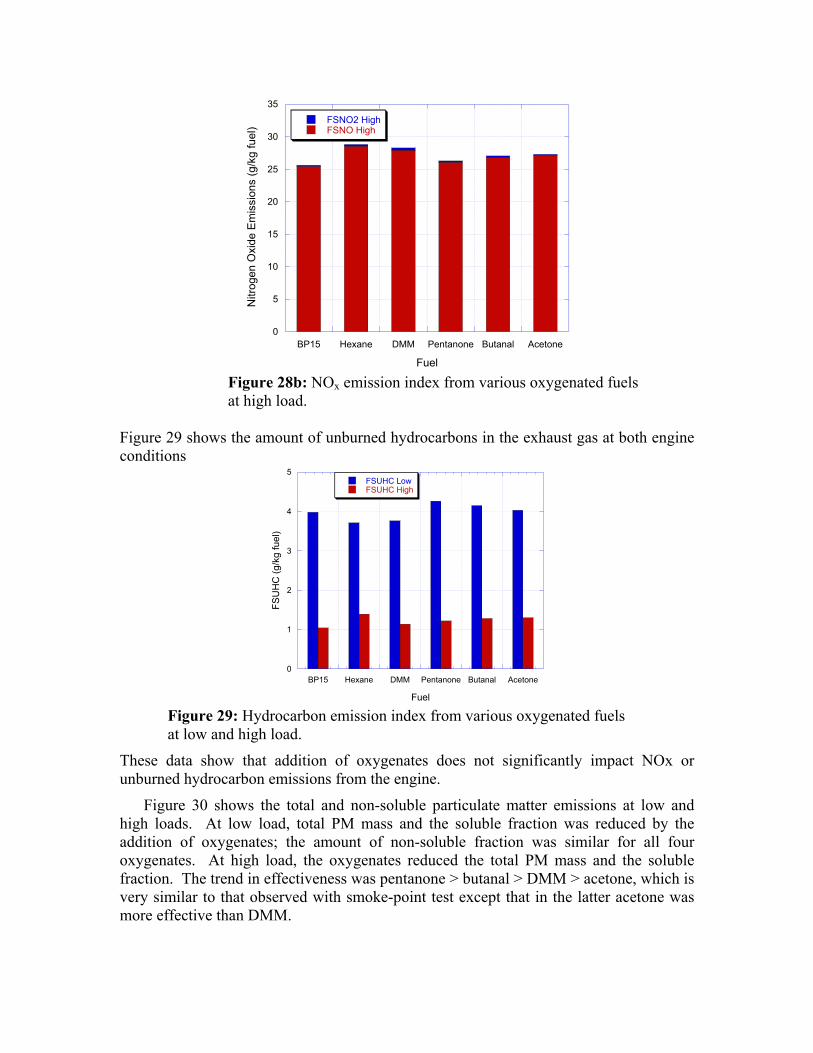
Fuel Figure 28b: NOx emission index from various oxygenated fuels at high load.
Figure 29 shows the amount of unburned hydrocarbons in the exhaust gas at both engine conditions
0
1
2
3
4
5
BP15 Hexane DMM Pentanone Butanal Acetone
FSUHC LowFSUHC High
FSU
HC
(g/k
g fu
el)
Fuel Figure 29: Hydrocarbon emission index from various oxygenated fuels at low and high load.
These data show that addition of oxygenates does not significantly impact NOx or unburned hydrocarbon emissions from the engine.
Figure 30 shows the total and non-soluble particulate matter emissions at low and high loads. At low load, total PM mass and the soluble fraction was reduced by the addition of oxygenates; the amount of non-soluble fraction was similar for all four oxygenates. At high load, the oxygenates reduced the total PM mass and the soluble fraction. The trend in effectiveness was pentanone > butanal > DMM > acetone, which is very similar to that observed with smoke-point test except that in the latter acetone was more effective than DMM.
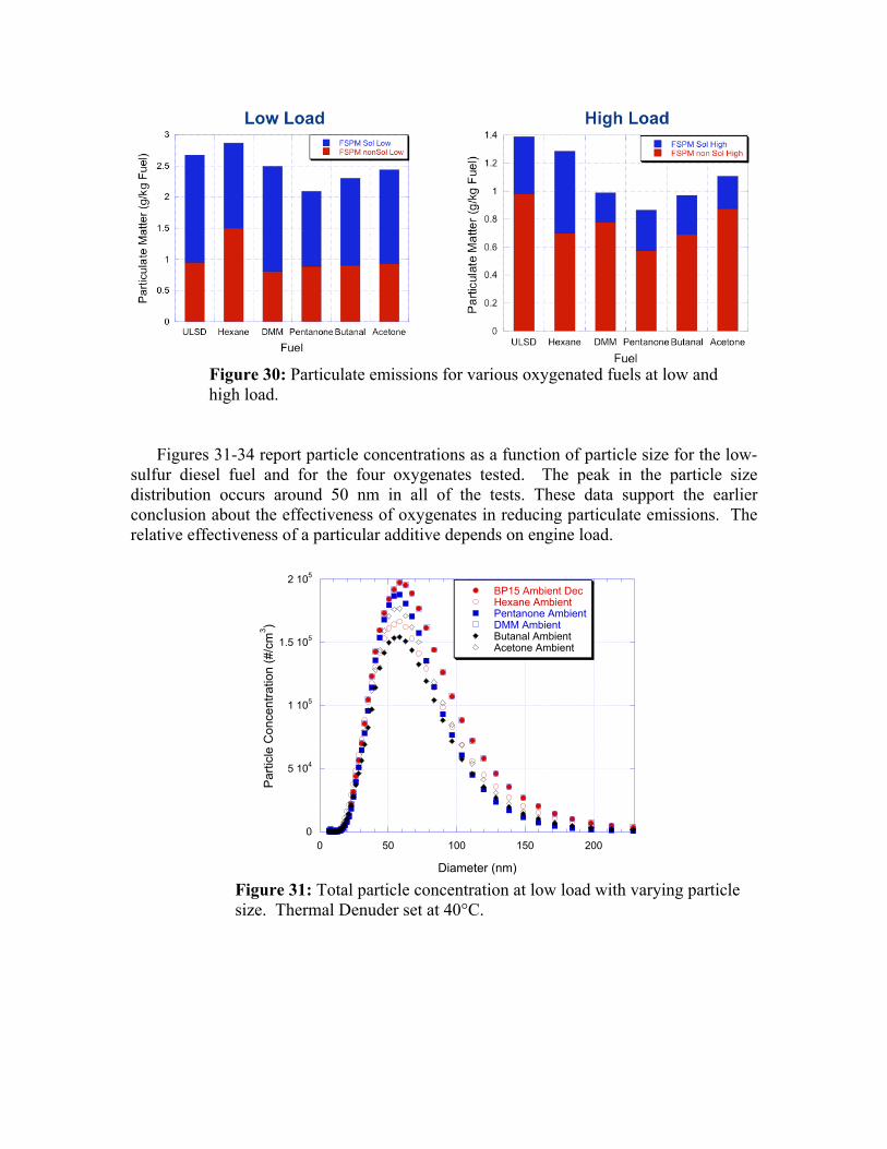
Figure 30: Particulate emissions for various oxygenated fuels at low and high load.
Figures 31-34 report particle concentrations as a function of particle size for the low-sulfur diesel fuel and for the four oxygenates tested. The peak in the particle size distribution occurs around 50 nm in all of the tests. These data support the earlier conclusion about the effectiveness of oxygenates in reducing particulate emissions. The relative effectiveness of a particular additive depends on engine load.
0
5 104
1 105
1.5 105
2 105
0 50 100 150 200
BP15 Ambient DecHexane AmbientPentanone AmbientDMM AmbientButanal AmbientAcetone Ambient
Par
ticle
Con
cent
ratio
n (#
/cm
3 )
Diameter (nm) Figure 31: Total particle concentration at low load with varying particle size. Thermal Denuder set at 40°C.

0
2 104
4 104
6 104
8 104
1 105
1.2 105
0 50 100 150 200
BP15 350 DecHexane 350Pentanone 350DMM 350Butanal 350Acetone 350
Par
ticle
Con
cent
ratio
n (#
/cm
3 )
Diameter (nm) Figure 32: Non-volatile particle concentration at low load with varying particle size.
0
5 104
1 105
1.5 105
2 105
0 50 100 150 200
BP15 Ambient DecHexane AmbientPentanone AmbientDMM AmbientButanal AmbientAcetone Ambient
Par
ticle
Con
cent
ratio
n (#
/cm
3 )
Diameter (nm) Figure 33: Total particle concentration at low load with varying particle size.
0
2 104
4 104
6 104
8 104
0 50 100 150 200
BP15 350 DecHexane 350Pentanone 350DMM 350Butanal 350Acetone 350
Par
ticle
Con
cent
ratio
n (#
/cm
3 )
Diameter (nm) Figure 34: Non-volatile particle concentration at high load with varying particle size.
While having little effect on engine performance and gaseous emissions the addition of an oxygenate, in any form, reduced the total mass of particulate generated during engine tests at both low and high load. Pentanone produced the greatest reduction in total particulate mass. Particle size data suggests that this reduction in mass was due to the decrease in large particle formation. The small particles present at low load appear to be mostly part of the VOF. At high load these volatile compounds were present to a lesser extent in the particulate matter, possibly due to the higher exhaust temperatures. At low load, in-cylinder conditions restrict fuel pyrolysis and therefore mute the sooting tendency of the fuel. At high load the diffusion burn is dominant, allowing fuel chemistry, or the sooting tendency of the fuel, to become more of a factor. Conclusions
Our experimental studies of effectiveness of various oxygenates in reducing sooting tendency of Diesel fuels has revealed the types of oxygen moieties that are most effective in reducing particulate emissions and has shown that the effectiveness of the moiety is independent of the molecule in which the groups appear. From all oxygenated groups, the carbonyl group consistently was found to be the most efficient. Ester and ether groups were also effective in reducing soot formation, but less than the carbonyl group.
Significant progress has been made in developing a simulation capability for Diesel
engine combustion and for soot formation in these engines. This capability will be important in optimizing synthetic oxygenated fuel-engine configurations for minimum particulate emissions.
The use of oxygenates as fuels, especially those derived from renewable sources, such
as algae, offers the prospects of reductions in GHG emissions owing to efficiency gains from advanced (i.e., low- or non-sooting) diesel engine concepts.
Publications and Presentations
1. .R. D. Cook, Davidson, D.F. and Hanson, R. K., High-temperature shock tube measurements of dimethyl ether decomposition and the reaction of dimethyl ether with OH,” submitted for publication to Journal of Physical Chemistry A, February 2009.
2. D. F. Davidson, Ranganath, S.C., Lam, K.Y., Liaw, M, Hong, Z. and Hanson, R. K., Ignition delay time measurements of normal alkanes and simple oxygenates, submitted for publication to Journal of Propulsion and Power, February 2009.
3. R. D. Cook, Davidson, D. F. and Hanson, R. K., Rate measurements of DME decomposition and DME+OH at elevated temperatures, Poster presentation U.S. Combustion Meeting, Ann Arbor MI, May 2009.
4. A. Bardos, Walters, K.M., Golden, D.M. and Bowman, C.T., Flow reactor studies of synthetic oxygenated fuels for Diesel engines, Poster presentation at the 32nd International Combustion Symposium, Montreal, Canada, August 2008.
5. Z. Hong, Davidson, D. F., Vasu, S.S. and Hanson, R.K., The effects of oxygenates on soot formation in rich heptane mixtures: a shock tube study, submitted for publication to Fuel: December 2008.
6. A. Farooq, Davidson, D.F., Hanson, R.K., Huynh, L.K. and Violi, A., “An experimental and computational study of methyl ester decomposition pathways using shock tubes,” Proceedings of the Combustion Institute 32 , 247-253, 2009.
7. R. D. Cook, Davidson, D.F., Hanson, R.K., “Shock tube measurements of ignition delay times and OH time-histories in dimethyl ether oxidation,” Proceedings of the Combustion Institute 32, 189-196, 2009.
8. Z. Hong, Davidson, D. F., Vasu, S. S. and Hanson, R.K., “Shock tube study of soot formation in rich heptane/oxygen mixtures with DME/Acetone/Butanal/3-Pentanone additives,” Poster presentation at the 32nd International Symposium on Combustion, Montreal Canada, August 2008.
9. Pepiot-Desjardins, P., Pitsch, H., Malhotra, R., Kirby, S.R. and Boehman, A.L., Experimental study and structural group analysis for soot reduction tendency of oxygenated fuels, Comb. Flame, 154, 191-205, 2008.
10. Z. Hong, Davidson, D.F. and Hanson, R.K, Shock tube studies of soot formation in rich heptane/oxygen mixtures with DME/Acetone/Butanal additives Paper 07F-34 2007 Fall Meeting of the Western States Section of the Combustion Institute, Livermore CA, October 2007.
11. R. D. Cook, Davidson, D.F. and Hanson, R.K., Measurements of ignition delay times and OH species concentration in DME/O2/Ar mixtures,” Paper 2970P International Symposium on Shock Waves 26, Heidelberg Germany July 2007.
12. Z. Hong, Davidson, D.F. and Hanson, R.K., Shock tube studies of soot formation in heptane and heptane/DME mixtures, Paper 2007-774 43rd AIAA Meeting, Reno NV, January 2007.
References
1. Pepiot-Desjardins, P., Pitsch, H., Malhotra, R., Kirby, S.R. and Boehman, A.L., Experimental study and structural group analysis for soot reduction tendency of oxygenated fuels, Comb. Flame, 154, 191-205, 2008.
2. Gill, R. J. and Olson, D. B., Estimation of soot thresholds for fuel mixtures, Combust. Sci. Technol. 40, 307-315, 1984.
3. Fischer, S.L., Dryer, F.L. and Curran, H.J., The reaction kinetics of dimethyl ether. I: High-temperature pyrolysis and oxidation in flow reactors, Int. J. Chem. Kinet. 32, 713-740, 2000.
4. Zhao, Z., Chaos, M., Kazakov, A. and Dryer, F.L., Thermal decomposition reaction and a comprehensive kinetic model of dimethyl ether, Int. J. Chem. Kinet. 40, 1-18, 2008.
5. Curran, H.J., Fischer, F.L. and Dryer, F.L., The reaction kinetics of dimethyl ether, II Low-temperature oxidation in flow reactors, Int. J. Chem. Kinet. 32, 741-759, 2000.
6. Huynh, L.K. and Violi, A., Thermal decomposition of methyl butanoate: ab initio study of a biodiesel fuel surrogate. J. Org. Chem. 73, 94-101 2008.
7. Dooley, S., Curran, H.J and Simmie, J.M., Autoignition measurements and a validated kinetic model for the biodiesel surrogate, methyl butanoate, Comb. Flame 153, 2-32, 2008.
8. Mittal, R. and Iaccarino, G. Immersed Boundary Methods, Ann. Rev. Fluid Mech. 37, 239-261 2005.
9. Kang, S., Iaccarino, G. and Ham, F., DNS of buoyancy-dominated turbulent flows on a bluff body using the immersed boundary method, J. Comp. Phys, 228, 3189-3208 2008. 10. Morinishi, Y., Vasilyev, O.V. and Ogi, T., Fully conservative finite difference scheme in
cylindrical coordinates for incompressible flow simulations, J. Comp. Phys. 197, 686-710, 2004. 11. O. Desjardins, O., Blanquart, G., Balarac, G. and Pitsch, H., High order conservative finite difference scheme for variable density low Mach number turbulent flows, J. Comp. Phys. 227, 7125-7159, 2008. 12. Thobois, L., Rymer, G., Souleres, T., Poinsot, T. Van den Heuvel, B.,. Large eddy simulations for
prediction of aerodynamics in IC engines, Int. J. Vehicle Design. 39, 368-382, 2005. 14. Morse, A.P., Whitelaw, J.H. and Yianneskis, M., Turbulent flow measurements by laser-doppler
anemometry in motored piston-cylinder assemblies, J. Fluids Eng. 28, 101, 1979. 15. Boree, J., Maure, S. and Bazile, R., Disruption of a compressed vortex, Phys. Fluids. 14, 2543,
2002. Contacts:
C. T. Bowman: [email protected] D. M. Golden: [email protected] R. K. Hanson: [email protected]

H. Pitsch: [email protected] R. Malhotra: [email protected] A. Boehman: [email protected]