Embed Size (px)
Citation preview

www.tjprc.org [email protected]
OPTIMIZATION OF PROCESS PARAMETERS IN MACHINING OF ALUMINIUM
K. HEMALATHA & V. SANDHYA
Associate Professor, Department of Mechanical Engineering, Muffakham Jah College of Engineering & Technology,
Banjara Hills, Hyderabad- 500 034
Assistant Professor, Department of Mechanical Engineering, Chaitanya Bharathi Institute of Technology,
Gandipet, Hyderabad- 500 075
ABSTRACT
Producing the requisite shape or surface quality is the main purpose of machining. The manufacturing parameters are
to be selected based on the requirement of geometry and surface finish. This paper focuses on optimization of
parameters during machining to obtain the required surface finish. In this paper the effects of varying speed, feed, and
depth of cut are studied. The influence of the machining parameters are analyzed using Taguchi optimization method.
L9 orthogonal array is built considering the three parameters and three levels for each parameter, corresponding to the
nine experimental tests. The influence of the parameters on the output are studied.
KEYWORDS: Machining, Surface Finish, Optimization, Orthogonal Array, Taguchi Method
1. INTRODUCTION
Machining operations are used to produce shapes or surface characteristics for a product. Some common
conventional machining operations are turning, boring, drilling, reaming, milling, and tapping. Conditions for
machining operations were chosen based on geometry and surface finish requirements rather than profit when costs
were comparatively low on labor, resource, machines, and tools [1].
The goal of the industry has always been the manufacturing of low-cost and high-quality products in a
short time. Modern industries try to enhance these characteristics. To achieve a high cutting performance, the
industry needs to operate close to the optimal cutting parameters [2].
The primary tooling concerns when machining aluminum are minimizing the tendency of aluminum to
stick to the tool cutting edges; ensuring there is good chip evacuation from the cutting edges ensuring there is good
chip evacuation from the cutting edge; and ensuring the core strength of the tool is sufficient to withstand the
cutting forces without breaking [3].
When machining aluminum, one of the major failure modes of cutting tools is the material being
machined adheres to the tool cutting edge. This condition rapidly degrades the cutting ability of the tool. The built-
up edge that is generated by the adhering aluminum dulls the tool so it can no longer cut through the material. Tool
material selection and tool coating selection are the two primary techniques used by tool designers to reduce the
occurrence of the built-up edge [4].
HMT lathe machines combine all those features that are expected in heavy duty production lathes. Some
of these features include great efficiency and high-end sliding, surfacing and screw cutting operation. These lathe
Orig
ina
l Article
International Journal of Mechanical and Production
Engineering Research and Development (IJMPERD)
ISSN(P): 2249–6890; ISSN(E): 2249–8001
Vol. 10, Issue 3, Jun 2020, 16547–16558
© TJPRC Pvt. Ltd.
Received: Jun 01, 2020; Accepted: Jun 20, 2020; Published: Jun 30, 2020; Paper Id.: IJMPERDJUN20201565

16548 K. Hemalatha & V. Sandhya
Impact Factor (JCC): 8.8746 NAAS Rating: 3.11
machines are easy to operate and install.
As lightweight metals are widely used, aluminum machining parts are becoming a choice of many
industries. The material and geometric parameters of the tool have an important influence on the cutting force and cutting
heat. The correct selection of the tool is essential to improve dimensional stability[6].
Cutting forces are generally low and because aluminum is a good conductor of heat and since most aluminum
alloys melt at temperatures between 500 and 600 °C, cutting temperatures and tool wear rates are also low. When cut under
proper conditions with sharp tools, aluminum alloys acquire fine finishes through turning, drilling and milling, minimizing
the necessity for grinding and polishing operations. Aluminum is commonly machined with high-speed steel, diamond and
carbide tooling; silicon nitride-based ceramic tools are generally not used with aluminum because of the high solubility of
silicon in aluminum. The major machinability concerned with aluminum alloys include tool life, chip characteristics, chip
disposal and surface finish [5].
2. METHODOLOGY
Systematic methodology has been adopted to conduct experiments and collect output data. Experiments are planned to
conduct in accordance with matrices of face centered central composite design (CCD). Three replicates for each
experimental run are considered and conducted in random order without bias. The machining has been carried out on
aluminumof 30 mm diameter up to the length of 50 mm. Material removal rate, surface roughness, axial force, Radial force
and feed force have been measured on each sample and the average values of three replicates are used for statistical
analysis. Furthermore, randomly the input variables are varied between their operating levels and experiments are
conducted.
The HMT Lathe with dynamometer on which the turning operation is carried is represented in the figure 1.
Figure 1: Lathe with Tool Dynamometer
The interfacing unit of the lathe tool Dynamometer is shown in figure 2 and 3

Optimization of Process Parameters in Machining of Aluminium 16549
www.tjprc.org [email protected]
Figure 2: Interfacing Transfer Unit
Figure 3: Lathe Tool Dynamometer PC Interfacing Setup
Experiments are carried out be using the L9 orthogonal array which is generate from the following three variables
at three levels represented in the table 1.
Table 1: Input Machining Parameters and their Operating Levels
Sl.
No.
Cutting
Parameters Units
Levels
Low Medium High
1 Speed (rpm) 88 114 192
2 Feed (mm/rev) 0.2 0.4 0.8
3 Depth of cut (mm) 0.5 1 1.5
The specimens after machining are shown in figure 4.

16550 K. Hemalatha & V. Sandhya
Impact Factor (JCC): 8.8746 NAAS Rating: 3.11
Figure 4: Specimens after Machining
The forces during turning are measured using the dynamometer and using the interface the graphs are obtained
from the PC monitor. The three forces variation during turning are shown if figure 5 to figure 13.
Figure 5: Graph Generated using PC Tool
Dynamometer for Specimen 1
Figure 6: Graph Generated using PC Tool
Dynamometer for Specimen 2
Figure 7: Graph Generated using PC Tool
Dynamometer for Specimen 3
Figure 8: Graph Generated using PC Tool
Dynamometer for Specimen 4

Optimization of Process Parameters in Machining of Aluminium 16551
www.tjprc.org [email protected]
Figure 9: Graph Generated using PC Tool
Dynamometer for Specimen 5
Figure 10: Graph Generated using PC Tool
Dynamometer for Specimen 6
Figure 11: Graph Generated using PC Tool
Dynamometer for Specimen 7
Figure 12: Graph Generated using PC Tool
Dynamometer for Specimen 8
Figure 13: Graph Generated using PC Tool
Dynamometer for Specimen 9
CUTTING FORCE
FEED FORCE
AXIAL FORCE
The surface roughness is measured using Surftest SJ-210, the details are shown in figure 14.

16552 K. Hemalatha & V. Sandhya
Impact Factor (JCC): 8.8746 NAAS Rating: 3.11
It includes
1. Display and transverse unit
2. Calibration standard
3. printer
4. Pick-up and diamond stylus
5. DP-1VR
Equipment Name: Surftest SJ-210
Figure 14: Surface Roughness Tester
The specifications are listed in the table 2.
Table 2: Specifications of surftest SJ-210
Measuring Range 350μm (-200 μm to +150 μm)
Digital Filter Gauss 2CR75,PC75
Customize setting Sampling Length 0.08mm,0.25mm,0.8mm,2.5mm,8mm.
No. of sampling (L) 1-10
Roughness Standards DIN EN ISO,VDA,JIS,ANSI
Analysis Graphs BAC, ADC.
Profile Roughness Profile (R),R-Motif,DF-profile and more
Parameters
Ra,Rq, Rz, Ry, Rp, Rv, Rt, R3z, Rsk, Rku, Rc, RPc, RSm, Rmax, Rz1max, S,
HSC, RzJIS, Rppi, RΔa, RΔq, Rlr, Rmr, Rmr(c), Rδc, Rk, Rpk, Rvk, Mr1, A1,
A2, Vo, λa, λq, Lo, Rpm, tp, Htp, R, Rx, AR,W, AW, Wx, Wte
Cut Off length λc : 0,08 mm, 0,25mm,0,8 mm, 2,5 mm, 8mm,
λs : 2,5 µm, 8 µm
Stylus Diamond Tip Skid radius 40mm
Power Battery or Mains (optional)
Mass 1.7kg
The specimens which are machined on the HMT Lathe NH22 are tested on the surftest SJ-210 tester for
determination of surface roughness. As the number of specimens are more in number. The results obtained are tabulated in
Optimization of Process Parameters in Machining of Aluminium 16553
www.tjprc.org [email protected]
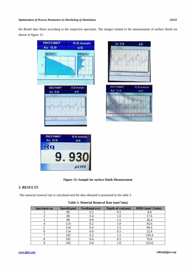
the Result data Sheet according to the respective specimen. The images related to the measurement of surface finish are
shown in figure 15.
Figure 15: Sample for surface finish Measurement
3. RESULTS
The material removal rate is calculated and the data obtained is presented in the table 3.
Table 3: Material Removal Rate (mm3/min)
Specimen no Speed(rpm) Feed(mm/rev) Depth of cut(mm) MRR (mm^3/min)
1 88 0.2 0.5 8.8
2 88 0.4 1.0 17.6
3 88 0.8 1.5 26.4
4 114 0.2 1.0 45.6
5 114 0.4 1.5 68.4
6 114 0.8 0.5 22.8
7 192 0.2 1.5 230.4
8 192 0.4 0.5 76.8
9 192 0.8 1.0 153.6

16554 K. Hemalatha & V. Sandhya
Impact Factor (JCC): 8.8746 NAAS Rating: 3.11
Taguchi Analysis: MRR (mm^3/min) versus Speed(rpm), Feed(mm/rev), Depth of cut(mm) is shown in figure 16
Figure 16: Variation of MRR
The forces measured during the turning operation are represented in the form of graph. The maximum force for
each iteration is obtained and represented in table 4.
Table 4: Maximum Force Obtained during Machining
SPECIMEN NO CUTTING FORCE FEED FORCE AXIAL FORCE
1 46 31 16
2 34 23 13
3 50 26 16
4 41 21 21
5 75 38 27
6 29 17 18
7 67 32 32
8 36 0 22
9 32 17 74
The Taguchi design is analyzed for forces and the graph is shown below in figure 17 and 18.

Optimization of Process Parameters in Machining of Aluminium 16555
www.tjprc.org [email protected]
Figure 17: Cutting Forces Mean Graph
Figure 18: Cutting Forces S/N Graph

16556 K. Hemalatha & V. Sandhya
Impact Factor (JCC): 8.8746 NAAS Rating: 3.11
The roughness average, Ten point mean roughness and Root Mean Square Roughness measured are represented in
the table 5.
Table 5: Surface Roughness
Specimen
No.
Roughness Average
R(a)
Ten-Point Mean
Roughness R(z)
Root Mean Square
Roughness R(q)
1 9.080 37.222 10.648
2 3.297 13.725 3.839
3 8.548 34.262 9.930
4 8.661 40.403 10.605
5 6.023 29.424 7.256
6 2.915 3.712 14.859
7 3.629 16.914 4.346
8 11.137 50.447 13.934
9 11.377 54.874 14.461
The Taguchi design is analyzed for surface finish and the graph is shown below in figure 19to 21

Optimization of Process Parameters in Machining of Aluminium 16557
www.tjprc.org [email protected]
Figure 19: Roughness Average Graph
Figure 20: Ten Point Mean Roughness Average Graph

16558 K. Hemalatha & V. Sandhya
Impact Factor (JCC): 8.8746 NAAS Rating: 3.11
Figure 21: Root Mean Square Roughness Graph
4. CONCLUSIONS
From the data analyzed it is clear that the MRR increases with increase in speed, feed, and depth of cut.
The forces are mainly influenced by depth of cut, the second influencing parameter being speed and the least
influencing parameter is feed.
The surface finish is mainly influenced by speed, the second influencing parameter being feed and the least
influencing parameter is depth of cut.
REFERENCES
1. Joao Eduardo Ribeiro, Manuel Braz Cesar, Hernani Lopes, Optimization of machining parameters to improve the surface
quality, Procedia Structural Integrity, Volume 5, 2017, Pages 355-362
2. N. Mandal, B. Doloi, B. Mondal, and R. Das, “Optimization of flank wear using Zirconia Toughened Alumina (ZTA) cutting
tool: Taguchi method and Regression analysis,” Measurement, vol. 44, no. 10, pp. 2149–2155, 2011.
3. A. Shokrani, V. Dhokia, and S. T. Newman, Environmentally conscious machining of difficult-to machine materials with
regard to cutting fluids, International Journal of Machine Tools and Manufacture, vol. 57, pp. 83-101, 2012.
4. K.M. Vernaza-Pena, J.J. Mason, M. Li ,Experimental study of the temperature field generated during orthogonal machining of
an aluminum alloy ,Exp. Mech., 42 (2002), pp. 221-229
5. G.C.Manjunath Patel, Deepak Lokare, Ganesh R.Chate, Mahesh B.Parappagoudar, R.Nikhil ,Kapil Gupta ,Analysis and
optimization of surface quality while machining high strength aluminium alloy
6. B. Chamberlain, Machinability of Aluminum Alloys, Metals Handbook, Vol. 2—Properties and Selection: Nonferrous Alloys
and Pure Metals, 9th Edition, ASME, 1979, pp. 187–190.