Embed Size (px)
Citation preview

Optimization of
non-evaporable getter coating
for accelerator beam pipe
O.B. Malyshev, R. Valizadeh,
B.T. Hogan, R.M.A. Jones, C. Naran,
M. Pendleton and A. Hannah
ASTeC Vacuum Science Group,
STFC Daresbury Laboratory, UK

Oleg Malyshev VS-4 , 16-17 October 2013, Ricoh Arena, Coventry, UK slide 2
Outlook
• Introduction
• What is NEG coatings
• Pumping property
• Film deposition
• Surface analysis
• NEG activation procedure
• Pumping properties
measurements
• Activation temperature
• Sticking probability and
capacity for different NEG
coatings
• Desorption properties
• How to reduce ESD
• What film is needed
• What achieved
• Conclusions

Oleg Malyshev VS-4 , 16-17 October 2013, Ricoh Arena, Coventry, UK slide 3
What are usual considerations for vacuum
Required pressure P is defined by gas
desorption Q in the vessel and effective
pumping speed Seff.
In a simple case it is
Q
Pump,
S (l/s)
P
U (l/s)
1 1
eff
QP Q
S S U
e e ion ionQ qA
Thermal, photon, electron and ion
stimulated desorption

Oleg Malyshev VS-4 , 16-17 October 2013, Ricoh Arena, Coventry, UK slide 4
Usual accelerator vacuum chamber
• Long tube with length L >> a, where a - transversal dimension
• Average pressure depends on vacuum conductance u(L,a) of
the beam vacuum chamber
1
12 2B
eff
LP qL k T
u S
P
z
L
Oleg Malyshev VS-4 , 16-17 October 2013, Ricoh Arena, Coventry, UK slide 5
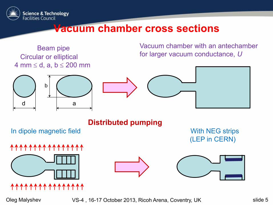
Vacuum chamber cross sections
Beam pipe
Circular or elliptical
4 mm d, a, b 200 mm
Vacuum chamber with an antechamber
for larger vacuum conductance, U
Distributed pumping In dipole magnetic field With NEG strips
(LEP in CERN)
d a
b

Oleg Malyshev VS-4 , 16-17 October 2013, Ricoh Arena, Coventry, UK slide 6
Two concepts of the ideal vacuum chamber Traditional:
• surface which outgasses as little as
possible (‘nil’ ideally)
• surface which does not pump
otherwise that surface is
contaminated over time
Results in
• Surface cleaning, conditioning,
coatings
• Vacuum firing, ex-situ baling
• Baking in-situ to up to 300C
• Separate pumps
‘New’ (C. Benvenuti, CERN, ~1998):
surface which outgasses as little as
possible (‘nil’ ideally)
a surface which does pump,
however, will not be contaminated
due to a very low outgassing rate
Results in
NEG coated surface
There should be no un-coated parts
Activating (baking) in-situ at 150-
180C
Small pumps for CxHy and noble
gases
Oleg Malyshev VS-4 , 16-17 October 2013, Ricoh Arena, Coventry, UK slide 7
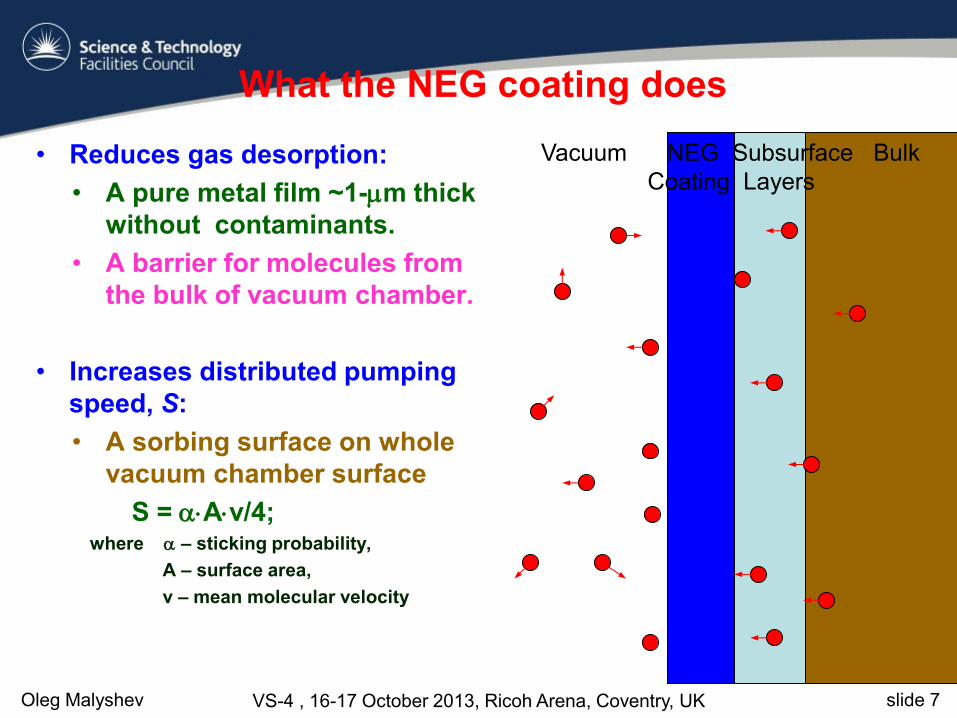
What the NEG coating does
• Reduces gas desorption:
• A pure metal film ~1-m thick
without contaminants.
• A barrier for molecules from
the bulk of vacuum chamber.
• Increases distributed pumping
speed, S:
• A sorbing surface on whole
vacuum chamber surface
S = Av/4; where – sticking probability,
A – surface area,
v – mean molecular velocity
Vacuum NEG Subsurface Bulk
Coating Layers

Oleg Malyshev VS-4 , 16-17 October 2013, Ricoh Arena, Coventry, UK slide 8
Deposition method
Planar magnetron deposition
8
Cylindrical magnetron deposition

Oleg Malyshev VS-4 , 16-17 October 2013, Ricoh Arena, Coventry, UK slide 9
Bulk and Surface Composition
RBS (film
composition in bulk) EDX
(determination of
film composition)
XPS (surface
composition
and chemical
bounding)

Oleg Malyshev VS-4 , 16-17 October 2013, Ricoh Arena, Coventry, UK slide 10
Region scan of XPS core levels of Ti, Zr, C,Hf and V of a Ti-Zr-V-Hf film
(surface composition and chemical bounding)

Oleg Malyshev VS-4 , 16-17 October 2013, Ricoh Arena, Coventry, UK slide 11
XRD of Film deposited from Ternary and Quaternary alloy wire as target.
In Both cases there is only one broad peak near 2 = 36.8°
The film is nearly amorphous.
11
TiZrVHf film deposited on Si by cylindrical magnetron using Alloy wire

Oleg Malyshev VS-4 , 16-17 October 2013, Ricoh Arena, Coventry, UK slide 12
ASTeC activation procedure
O.B. Malyshev, K.J. Middleman, J.S. Colligon and R. Valizadeh. J. Vac. Sci. Technol. A 27 (2009), p. 321.

Oleg Malyshev VS-4 , 16-17 October 2013, Ricoh Arena, Coventry, UK slide 13
Quaternary NEG alloy film deposited on Si test sample from twisted Ti, V, Zr, and Hf wires.
Cylindrical Magnetron: Power = 60 W, PKr = 10-2 mbar, deposition rate = 0.12 nm/s, T = 120°C.
Very glassy structure.

Oleg Malyshev VS-4 , 16-17 October 2013, Ricoh Arena, Coventry, UK slide 14
Initial sticking
probability can be
obtained from
pressure ratio
Pbottom / Ptop
Pumping properties measurements
H2, CO and CO2 injection
pumping capacity taken at Pbottom / Ptop = 10
Oleg Malyshev VS-4 , 16-17 October 2013, Ricoh Arena, Coventry, UK slide 15
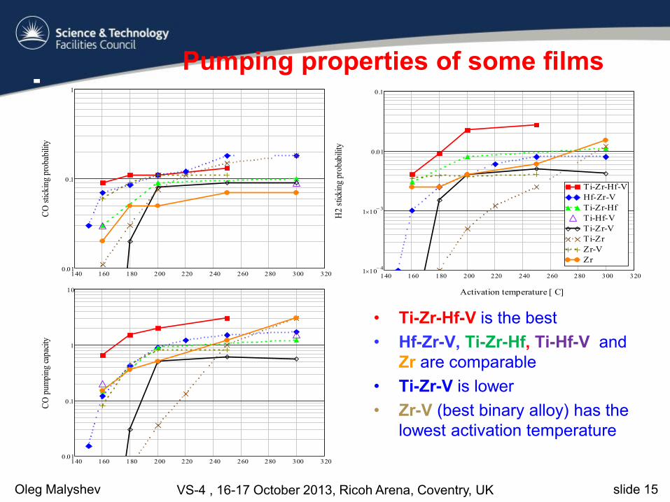
Pumping properties of some films
• Ti-Zr-Hf-V is the best
• Hf-Zr-V, Ti-Zr-Hf, Ti-Hf-V and
Zr are comparable
• Ti-Zr-V is lower
• Zr-V (best binary alloy) has the
lowest activation temperature
140 160 180 200 220 240 260 280 300 3200.01
0.1
1
CO
stic
king
pro
babi
lity
140 160 180 200 220 240 260 280 300 3201 10
4
1 103
0.01
0.1
Ti-Zr-Hf-V
Hf-Zr-V
Ti-Zr-Hf
Ti-Hf-V
Ti-Zr-V
Ti-Zr
Zr-V
Zr
Activation temperature [ C]
H2
stic
king
pro
babi
lity
140 160 180 200 220 240 260 280 300 3200.01
0.1
1
10
CO
pum
ping
cap
acity

Oleg Malyshev VS-4 , 16-17 October 2013, Ricoh Arena, Coventry, UK slide 16
where
• - desorption yield
• - sticking probability
Pressure in the accelerator vacuum chamber
16
• Improving the pumping
properties is limited:
1.
0.005 < H2 < 0.01
0.1 < CO < 0.5
0.4 < CO2 < 0.6
• Reducing the desorption
yields in orders of
magnitude is a realistic
task
P

Oleg Malyshev VS-4 , 16-17 October 2013, Ricoh Arena, Coventry, UK slide 17
Reducing the gas desorption from the NEG coatings
• Main gases in the NEG coated vacuum chamber are H2 and
CH4
• Only H2 can diffuse through the NEG film under
bombardment or heat
• CH4 is most likely created on the NEG surface from
diffused H2 and C (originally from sorbed CO and CO2)
• Therefore the H2 diffusion must be suppressed
• Where H2 come from?

Oleg Malyshev VS-4 , 16-17 October 2013, Ricoh Arena, Coventry, UK slide 18
Reducing the gas desorption from the NEG coatings
Vacuum
NEG
Coating
Subsurface
Layers
Bulk
Gas molecules are contained
on the NEG coating surface
after exposure to air
minimise exposure to air
inside the NEG coating
trapped during deposition
purity of discharge gas
background pressure
in subsurface substrate layer
substrate bakeout before NEG
deposition
in the substrate bulk
vacuum firing

Oleg Malyshev VS-4 , 16-17 October 2013, Ricoh Arena, Coventry, UK slide 19
Electron stimulated desorption rig
ESD is studied as a function of • Electron energy
• Dose
• Wall temperature (-5 to +70C)
• Activation/bakeout temperature
Can be used for samples with:
• Specially treated samples
• Vacuum fired, polished, etc.
• Low desorption coating
• No coatings
• NEG coating
• ESD measurements
• Sticking probability
measurements
O.B. Malyshev, A.P. Smith et al. J. Vac. Sci. Technol. A 28 (2010), p. 1215.

Oleg Malyshev VS-4 , 16-17 October 2013, Ricoh Arena, Coventry, UK slide 20
Experimental procedure for NEG coated samples

Oleg Malyshev VS-4 , 16-17 October 2013, Ricoh Arena, Coventry, UK slide 21
SEM images of films (film morphology )
columnar (TiZrVHf) dense (TiZrVHf) Best for pumping A first candidate for a barrier

Oleg Malyshev VS-4 , 16-17 October 2013, Ricoh Arena, Coventry, UK slide 22
ESD yield from NEG coated samples

Oleg Malyshev VS-4 , 16-17 October 2013, Ricoh Arena, Coventry, UK slide 23
ESD yield from NEG coated samples

Oleg Malyshev VS-4 , 16-17 October 2013, Ricoh Arena, Coventry, UK slide 24
ESD yield from NEG coated samples

Oleg Malyshev VS-4 , 16-17 October 2013, Ricoh Arena, Coventry, UK slide 25
Conclusions
• ASTeC activation procedure minimises NEG poisoning from non-coated
vacuum chamber components
• Role of element:
• Zr-based – highest sticking probability and capacity, lowers activation temp.
• Ti-based – lowest sticking probability and capacity, highest activation temp
• Role of grain size
• Activation temperature reduces with a grain size due to increase the grain
boundary density
• Quaternary alloy demonstrated the lowest activation temperature and best
pumping properties;
• Pure Zr film is good as well
• Alloy target is better than twisted wires
• The improvement and further development of NEG coatings requires
• Intensive use surface analysis techniques
• Evaluation under photon, electron and ion bombardment.