Embed Size (px)
Citation preview
Optimization of BGP Convergence and
Prefix Security in IP/MPLS Networks
UNIVERSITY OF TURKU
Department of Computing Master of Science in Technology Thesis
Communication and Cyber Security Engineering November 2021 Koskinen, Jesse
Supervisors:
M. Sc. (Tech) Raikisto, Vesa - DNA Plc.
Examiners: D. Sc. (Tech) Virtanen, Seppo - University of Turku
M. Sc. (Tech) Sainio, Petri - University of Turku
The originality of this thesis has been checked in accordance with the University of Turku quality assurance system using the Turnitin OriginalityCheck service.
UNIVERSITY OF TURKU
Department of Computing
Koskinen, Jesse: Optimization of BGP Convergence and
Prefix Security in IP/MPLS Networks
Master of Science in Technology Thesis, 125 p., 3 app. p.
Communication and Cyber Security Engineering
November 2021
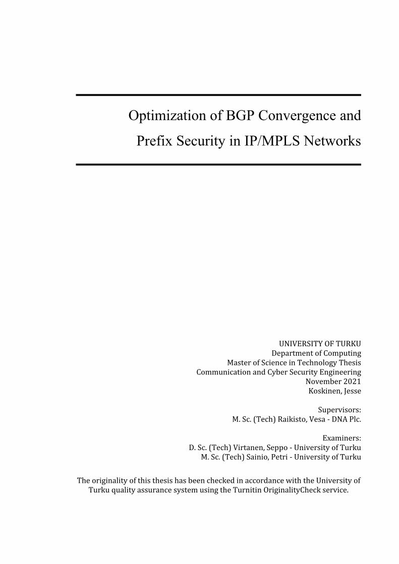
Multi-Protocol Label Switching-based networks are the backbone of the operation
of the Internet, that communicates through the use of the Border Gateway Protocol
which connects distinct networks, referred to as Autonomous Systems, together.
As the technology matures, so does the challenges caused by the extreme growth
rate of the Internet. The amount of BGP prefixes required to facilitate such an
increase in connectivity introduces multiple new critical issues, such as with the
scalability and the security of the aforementioned Border Gateway Protocol.
Illustration of an implementation of an IP/MPLS core transmission network is
formed through the introduction of the four main pillars of an Autonomous
System: Multi-Protocol Label Switching, Border Gateway Protocol, Open Shortest
Path First and the Resource Reservation Protocol. The symbiosis of these
technologies is used to introduce the practicalities of operating an IP/MPLS-based
ISP network with traffic engineering and fault-resilience at heart.
The first research objective of this thesis is to determine whether the deployment
of a new BGP feature, which is referred to as BGP Prefix Independent Convergence
(PIC), within AS16086 would be a worthwhile endeavour. This BGP extension aims
to reduce the convergence delay of BGP Prefixes inside of an IP/MPLS Core
Transmission Network, thus improving the networks resilience against faults.
Simultaneously, the second research objective was to research the available
mechanisms considering the protection of BGP Prefixes, such as with the
implementation of the Resource Public Key Infrastructure and the Artemis BGP
Monitor for proactive and reactive security of BGP prefixes within AS16086.
The future prospective deployment of BGPsec is discussed to form an outlook to
the future of IP/MPLS network design. As the trust-based nature of BGP as a
protocol has become a distinct vulnerability, thus necessitating the use of various
technologies to secure the communications between the Autonomous Systems that
form the network to end all networks, the Internet.
Keywords: MPLS, LSP, BGP, OSPF, RSVP, SLA, PIC, RPKI, Artemis, BGPsec

For my late grandfather Mikko, who inspired me to continue my academic studies.

Foreword
After my studies at the Satakunta University of Applied Sciences had ended in 2018, I started my work within the Transmission Network Operations Group of DNA Plc. As a newly-graduated Bachelor of Engineering, working with the operational and technological aspects of a complex IP/MPLS network was the realisation of my occupational hopes and dreams at the time. During the late autumn of 2018, my grandfather Mikko, who had always recommended that I would return to the world of academia for further studies, passed away. To honour my promise to my late grandfather, I restarted my academic pursuits in 2020 by enrolling to a university as the first of my family to do so. Three years after his passing, I am fulfilling the promise I had made to my grandfather, by completing a milestone on my journey for a Master of Science degree on Information Security, Cryptography, and Communications Engineering. Above all, I would like to thank the supervisors and examiners of this thesis: Vesa Raikisto, Seppo Virtanen and Petri Sainio, who have guided me through the process of refining this work. Their support and advice have been remarkably useful in the formation and revision process of this Master’s Thesis. I would like to thank my former and current lecturers, colleagues, and friends for their support and companionship throughout my combined studies: Samuli Könönen, Petrus Vasenius, Janne Marjalaakso, Robert Blomkvist, Vili Pohjola, Santeri Saari, Niklas Syväkuru, Samuli Saari, Tommi Kangas, Samuli Oksanen, Ville Ritola, Juha Aromaa and others I’ve had the pleasure of meeting during my studies. From my team at DNA Plc., a warm thank you to Tommi Raitanen, Tero Laakkonen, Jaakko Solismaa, Simo Aromaa, Olli Mäntylä, Ronny Malmberg, Visa Urpelainen, Jyri Hyökki, Jari Haapasaari, Juuso Karikorpi, and others, for your patience and tutorship during my years at the Core and IP Networks Group of DNA Plc. This thesis signals my transition to the field of information security, thus presenting a fitting epilogue for my studies in Turku. Hopefully, in the far distant future, I will grasp upon the handle of a doctoral sword after a successful D. Sc. dissertation. Until then, this thesis will stand as the epitome of my combined academic studies and working career experience. As this foreword is written on the 103rd anniversary of the Armistice of Compiègne that ended the Great War in 1918, I will end on the words often attributed to the famous Prussian pilot “The Red Baron”, Manfred Albrecht Freiherr von Richthofen: “Fight on and fly on to the last drop of blood and the last drop of fuel, to the last beat of the heart.“
In Vaasa, Ostrobothnia November 11th, 2021
Koskinen, Jesse
Table of Contents
1 Introduction ................................................................................... 1
2 Theoretical Background ............................................................... 6
2.1 MPLS, Multiprotocol Label Switching ............................................................................... 6
2.1.1 MPLS Header ..................................................................................................................................... 8
2.1.2 MPLS Label ......................................................................................................................................... 9
2.1.3 Label Signaling ............................................................................................................................... 11
2.1.4 Label Switched Paths .................................................................................................................. 13
2.1.5 Evolution of MPLS ........................................................................................................................ 15
2.2 BGP, Border Gateway Protocol .......................................................................................... 17
2.2.1 Foundations of BGP ...................................................................................................................... 17
2.2.2 BGP Operation ................................................................................................................................ 20
2.2.3 BGP Route Processing ................................................................................................................. 22
2.2.4 Implementations of BGP ............................................................................................................ 23
2.2.5 Evolution of BGP ........................................................................................................................... 27
2.3 OSPF, Open Shortest Path First ......................................................................................... 28
2.3.1 Forming an OSPF Network ....................................................................................................... 29
2.3.2 Function of OSPF ........................................................................................................................... 32
2.3.3 Integration of OSPF-TE and OSPFv3 ..................................................................................... 36
2.4 RSVP, Resource Reservation Protocol ............................................................................ 37
2.4.1 Fundamentals of RSVP ................................................................................................................ 37
2.4.2 Operation of RSVP ........................................................................................................................ 39
2.4.3 Integration of RSVP-TE ............................................................................................................... 41
3 Practical Background ................................................................. 42
3.1 MPLS Core Transmission Networks ................................................................................ 42
3.1.1 Interconnection of Autonomous Systems ........................................................................... 44
3.1.2 Design of an Autonomous System.......................................................................................... 47
3.1.3 Resiliency of MPLS Networks .................................................................................................. 49
3.1.4 Management of Routing Disruptions .................................................................................... 51
3.2 Security of BGP Prefixes....................................................................................................... 52
3.2.1 BGP Prefixes & Hijacking ........................................................................................................... 52
3.2.2 Case Study: “The AS17557 Incident” .................................................................................... 55
4 BGP Prefix Independent Convergence ..................................... 57
4.1 BGP Convergence ................................................................................................................... 57
4.1.2 Proposed Mitigations .................................................................................................................. 58
4.1.3 Prefix Independent Convergence ........................................................................................... 59
4.1.4 Benefits of Prefix Independent Convergence .................................................................... 62
4.2 Deployment of Prefix Independent Convergence ...................................................... 63
4.2.1 Cisco Systems ................................................................................................................................. 63
4.2.2 Juniper Networks .......................................................................................................................... 65
4.2.3 Huawei Technologies .................................................................................................................. 67
5 BGP Prefix Security ................................................................... 68
5.1 Proactive Mitigation: RPKI.................................................................................................. 68
5.1.1 Deployment of RPKI .................................................................................................................... 71
5.1.2 Operation of RPKI ......................................................................................................................... 73
5.1.3 Challenges of RPKI........................................................................................................................ 74
5.2 Reactive Mitigation: Artemis.............................................................................................. 76
5.2.1 Background & Function.............................................................................................................. 76
5.2.2 Adoption of Artemis .................................................................................................................... 81
5.2.3 Network Integration .................................................................................................................... 85
5.3 The Future: BGPsec................................................................................................................ 86
5.3.1 The Promise of BGPsec ............................................................................................................... 86
5.3.2 Challenges of BGPsec ................................................................................................................... 90
6 Analysis ........................................................................................ 93
6.1 Prefix Independent Convergence ..................................................................................... 93
6.2 Prefix Security ......................................................................................................................... 98
7 Conclusion ................................................................................. 102
7.1 Future Work .......................................................................................................................... 105
References ........................................................................................ 107
Appendices ....................................................................................... 117 Appendix A: RPKI Route Origin Validation Configuration .......................................... 117 Appendix B: Configuration of Artemis ................................................................................ 118 Appendix C: Artemis Hijack Classification ........................................................................ 118 Appendix D: Artemis Installation Process......................................................................... 119
Abbreviations and Acronyms
ABR Area Border Router
AMSIX Amsterdam Internet Exchange
AE Aggregated Ethernet
AES Advanced Encryption Standard
AIGP Accumulated Interior Gateway Protocol
AS Autonomous System
ASBR Autonomous System Border Router
ASPP Autonomous System Path-Prepending
ATM Asynchronous Transfer Mode
BDR Backup Designated Router
BGP Border Gateway Protocol
BGPsec Border Gateway Protocol Security
BS Base Station
CAPEX Capital Expenditure
CE Customer Edge (Router)
CEF Cisco Express Forwarding
COS Class of Service
DECIX Deutscher Commercial Internet Exchange
DEMUX Demultiplexer (WDM)
DR Designated Router
DWDM Dense Wavelength Division Multiplexing
eBGP External Border Gateway Protocol
eLER Egress Label Edge Router
ERO Explicit Route Object
FEC Forward Equivalence Class
FIB Forwarding Information Base
FWA Fixed Wireless Access (5G)
G-MPLS Generalized Multiprotocol Label Switching
iBGP Internal Border Gateway Protocol
IEEE Institute of Electrical and Electronics Engineers
IETF Internet Engineering Task Force
IGP Interior Gateway Protocol
iLER Ingress Label Edge Router
IP Internet Protocol (v4 / v6) ISP Internet Service Provider
IXP Internet Exchange Point
JSON JavaScript Object Notation
LDP Label Distribution Protocol
LER Label Edge Router
LINX London Internet Exchange
LPU Line Processing Unit
LSA Link-State Advertisement
LSDB Link-State Database
LSP Label Switched Path
LSR Label Switching Router
MC-LAG Multi-Chassis Link Aggregation Group
MED Multiple Exit Discriminator
MIMO Multiple Input Multiple Output
MPC Multi-Party Computation
MPLS Multiprotocol Label Switching
MPLS-TE Multiprotocol Label Switching – Traffic Engineering
MPLS-TP Multiprotocol Label Switching – Transport Profile
MRAI Minimum Route Advertisement Interval
MSP Multi-Service Provider
MTU Maximum Transmission Unit MUX Multiplexer (WDM)
NLRI Network Layer Reachability Information
NNI Network-to-Network Interface
NOC Network Operations Centre
NSSA Not-So-Stubby Area
OPEX Operational Expenditure
OSPF Open Shortest Path First
OSPF-TE Open Shortest Path First – Traffic Engineering
OSPFv3 Open Shortest Path First Version 3 (IPv6)
P Provider (Router)
PE Provider Edge (Router)
PIC Prefix Independent Convergence
QoS Quality of Service
RE Routing Engine
RFC Request for Comments
RFO Reason for Outage
RIB Routing Information Database
RIPE Réseaux IP Européens
RIR Regional Internet Registry
ROA Route Origin Authorization
ROV Route Origin Validation
RPKI Resource Public Key Infrastructure
RR Route Reflector
RRDP RPKI Repository Delta Protocol
RSVP Resource Reservation Protocol
RSVP-TE Resource Reservation Protocol – Traffic Engineering
SDH Synchronous Data Hierarchy
SDN Software Defined Networking
SLA Service Level Agreement
SOC Security Operations Centre
SONET Synchronous Optical Network
TCP Transmission Control Protocol
TDM Time-Division Multiplexing
TTL Time To Live
UDP User Datagram Protocol
VPN Virtual Private Network
WDM Wavelength Division Multiplexing

Sag, Fremdling, zu Sparta, du habest uns hier liegen sehen,
wie wir die heiligen Gesetze des Vaterlands befolgten.
Tell, stranger, to Sparta that you saw us lying here,
since we followed the sacred laws of the fatherland.
Dic, hospes, Spartae nos te hic vidisse iacentes
dum sanctis patriae legibus obsequimur.
Ὦ ξεῖν', ἀγγέλλειν Λακεδαιμονίοις ὅτι τῇδε
κείμεθα τοῖς κείνων ῥήμασι πειθόμενοι
The Battle of Thermopylae
Tusculanae Disputationes
Marcus Tullius Cicero [1]
1
1 Introduction
The reliable and fault-resilient function of the Border Gateway Protocol is the most
critical factor in the operation of the World Wide Web, enabling the connectivity
between the distinct Autonomous Systems that form the basic functional fabric of
the Internet, the network to end all networks.
The function of the BGP due to its nature as a non-security orientated protocol is
under attack from multiple fronts, such as with the malicious propagation of BGP
prefixes, which results in the hijacking of the traffic associated with the prefix.
Thus, multiple proposals of security-oriented extensions to the original protocol
have been made to incrementally increase the security of the Border Gateway
Protocol, such as the RPKI (Resource Public Key Infrastructure) and BGPsec
(Secure Border Gateway Protocol). These proposals have been made in order to
secure the basic fundamental BGP routing capabilities within the Internet.
A BGP hijacking incident effectively reroutes the legitimate traffic of an associated
BGP prefix to a malicious Autonomous System, such as with the incident that
occurred concerning AS17557. The aforementioned incident effectively rendered
the online video-streaming platform YouTube unusable for multiple hours. Thus,
as such a break could cause user privacy-related concerns extensive financial
losses for the affected AS, the overall security of the BGP announcements is a
critical security concern for an operator of an Autonomous System.
In addition to the hijacking of BGP prefixes, the convergence of BGP routes is a
similarly critical issue for an operator of a BGP-enabled Autonomous System.
As the amount of BGP prefixes processed and propagated by various IP/MPLS
network operators increases with the never-ending advancement of technology,
the process of efficient BGP route convergence becomes an increasingly critical
problem for the IP/MPLS network operators.
2
The amount of processing required to restore the traffic after a network fault,
colloquially referred to as “BGP churn”, is increasing, thus introducing a delay
before such traffic restoration would occur. This delay in convergence is a distinct
disadvantage of BGP, that all operators need to consider in their operation. The
inefficient speed of convergence of BGP routes, which can be argued to stem from
the serialized nature of the traffic restoration within the Border Gateway Protocol,
which was not designed to manage millions of BGP prefixes. As the Internet
evolved, BGP has necessitated the creation of multiple technologies to improve the
scalability of the protocol, such as with the extensive use of Route Reflectors in
IP/MPLS-based networks running iBGP.
This delay in route convergence increases the amount of time, within which
network traffic is effectively lost, thus introducing new challenges in the adherence
to the strict requirements of Service Level Agreement contracts that are especially
common for Internet Service Providers. Additionally, as ISPs often provide
connectivity to operationally-critical systems, such as medical facilities and
military applications, the effect of an unannounced and sudden break can be fatal,
as in some cases even emergency calls can be blocked due to such a break. As such
an incident is to be considered unacceptable, the number of redundancies and
optimizations to the BGP route convergence speed of such a critical connection
need to be implemented in conjunction with thorough change and incident
management processes.
Therefore, a significant reduction in the convergence time of BGP routes required
before traffic restoration would occur is to be considered a critically valuable effort
for an ISP responsible for such connectivity. As such, as the implementation of BGP
Prefix Independent Convergence can stand to improve the current method of
convergence. This would be achieved through implementing a processing method
which allows for the decoupling of the time that the router would need to converge
the affected routes from the amount of BGP prefixes the router would manage.
3
Thus, with the introduction of a non-serialized method of convergence with BGP
Prefix Independent Convergence, the ability of the Autonomous System to meet the
expectations of their high-priority customers and disruption-sensitive systems can
be increased tremendously, therefore enabling a significant improvement in the
fault-resiliency and responsiveness of the IP/MPLS network BGP Prefix
Independent Convergence feature would be deployed in.
This thesis proposes the implementation of three technologies to improve both the
speed of convergence and the overall security of the Border Gateway Protocol.
These technologies such as the BGP Prefix Independent Convergence, Resource
Public Key Infrastructure and the Artemis BGP monitoring tool were chosen in
accordance with the request of the benefactor of this thesis, DNA Plc.
Operating the Autonomous System 16086 as subsidiary of the Norwegian
multinational Telenor telecommunications company, DNA Plc is the market leader
in fixed-network broadband connectivity in Finland. As a former Junior Specialist
within the Transmission Network Operations Group of DNA Plc., the author of this
thesis has gathered an extensive practical experience about the function of an
Autonomous System during the author’s years working there.
The rest of this thesis is organized as follows, divided into seven distinctive
chapters which cover various aspects considering the function, optimization, and
security of the Border Gateway Protocol in networks that employ the Multi-
Protocol Label Switching as the foundational protocol of their network.
The second chapter covers the four fundamental pillars of an IP/MPLS-based
network, namely the Multi-Protocol Label Switching (MPLS), Border Gateway
Protocol (BGP), Open Shortest Path First (OSPF) and Resource Reservation
Protocol (RSVP). The description of these four protocols is used to illustrate the
theoretical high-level function of an Autonomous System that employs such
protocols, with traffic engineering and fault-resiliency at the heart.
4
In the operation of an Autonomous System that is operated by a Tier 2 Internet
Service Provider, several distinctive traffic engineering, network monitoring and
fault & change management processes are followed, which are discussed in the
third chapter of this thesis. This description is made as to introduce the reader to
the operational nuances of operating such a network, therefore simultaneously
justifying the decisions made in the sixth and seventh chapters of this thesis.
The fourth chapter covers the contemporary situation with the BGP convergence
process, and the improvements that the BGP Prefix Independent Convergence
feature would enable in replacing the traditional route convergence method. Thus,
with fault-resiliency and the speed of convergence in mind, the implementation of
BGP PIC is discussed on a vendor-by-vendor basis, with IP/MPLS routing platform
vendors such as Cisco Systems, Juniper Networks and Huawei Technologies.
Considering the security of BGP prefixes, the fifth chapter covers the two solutions
proposed by this thesis such as the open-source Artemis software and RPKI
(Resource Public Key Infrastructure), for an increase of the overall reactive and
proactive security, respectively. The function, implementation, and the symbiotic
relationship between these two technologies is discussed, with a focus on securing
various aspects of the operation of the Border Gateway Protocol.
For the purpose of providing an overview into the future of IP/MPLS network
design, the fifth chapter also briefly covers the proposed extension of the Border
Gateway Protocol, which is referred to as BGPsec. This protocol, while reliant on
the existence of the aforementioned RPKI architecture, looks to provide a method
of BPG path-validation method through the introduction of cryptographical
signatures to the BGP routing process. Therefore, BGPsec aims to increase the
overall security of the Border Gateway Protocol with increasing the difficulty of
propagating malicious BPG advertisements across multiple Autonomous Systems.
5
The penultimate chapter ponders on the implementability of aforementioned
technologies described in the fourth and fifth chapters and forms a proposal for
their incremental implementation in the IP/MPLS network operated by the
Autonomous System 16086. High-level managerial and technical implementation
concerns, such as CAPEX & OPEX spending and interoperability between different
IP/MPLS routing platform vendors are discussed as to form justifications for the
recommendations and decisions made in the seventh chapter of this thesis.
The seventh chapter of this thesis concludes on the proposal that Artemis, BGP
Prefix Independent Convergence and the Resource Public Key Infrastructure
should be implemented within the IP/MPLS network of Autonomous System
16086 as the benefits from their implementation far outweigh the difficulty
associated with the incremental process of deploying these technologies.
Thus, the incremental deployment of the Artemis BGP monitoring tool, BGP Prefix
Independent Convergence and the Resource Public Key Infrastructure is to be
considered a beneficial choice for Autonomous System 16086, in preparation for
the impending final specification and vendor-specific implementations of the
BGPsec protocol extension. Reliant on the aforementioned technologies, an
optimistic view of the hypothetical implementation of the BGPsec protocol is
illustrated, with the technology considered to be an integral part of the future
considerations related to the secure operation of IP/MPLS networks.
The improvement to the overall function and the resiliency of the AS16086
provided by these three technologies can be ascertained from the substantially
increased resiliency against interfering events, such as sudden fibre breaks,
hardware failures and more malicious events i.e., malicious BGP advertisements
and BGP hijacking incidents. Therefore, their implementation is the recommended
action this thesis proposes for the network operators of AS16086.
6
2 Theoretical Background
This chapter covers the theoretical background that the thesis relies upon, through
introducing the core concepts and protocols used in the implementation of an
IP/MPLS-based core transmission network such as MPLS (Multi-Protocol Label
Switching), BGP (Border Gateway Protocol), OSPF (Open Shortest Path First) and
RSVP (Resource ReserVation Protocol).
2.1 MPLS, Multiprotocol Label Switching
Multi-Protocol Label Switching (MPLS) is a core networking technology, which was
initially proposed by the IETF under the Request for Comments (RFC) 3031
authored by Rosen, Viswanathan & Callon [2], which specified the architecture for
the implementation of MPLS in core networks utilized by Internet Servicer
Providers. The initial specification was then iterated and expanded upon among
others by RFC 6178 by Smith, Jaeger & Scholl [3] and RFC 6790 by Kompella,
Drake et. al. [4].
MPLS in current form is used in the networks of various Internet Service Providers
(ISPs) and other organizations both public and private in nature. These networks
are congregated into Autonomous Systems (AS) such as AS16086 used by DNA
Plc., AS719 for Elisa Corporation, and AS1759 which is used by Telia Finland Plc.
The aforementioned three Autonomous Systems can be considered to form the
fundamental basis of the Finnish internet service provider spectrum.
The primary of benefits for Internet Service Providers and other larger networks
gained through the usage of MPLS technology is considered to be the increase of
flexibility and scalability of the network-layer routing decisions, network
performance and the simplification of the IP forwarding process itself. This
increase in routing efficiency is achieved through the introduction of MPLS labels,
which simplify the process of route determination significantly.
7
The most practical way of summarizing MPLS on the OSI Layer model [5] would be
to call it a “Layer 2.5” networking protocol. While the Layer 2 is formed protocols
through protocols such as Ethernet & SONET, whereas the third layer is comprised
of IP-protocol in Internet-wide routing and addressing. MPLS operates on both of
these traditional layers providing features for both the transport and data layers
concerning the transmission of data throughout the network. Thus, the Layer 2.5
classification would be practical to describe MPLS’s position on the OSI model.
As for the historical basis of MPLS as a technology, the development of the
technology began with the foundation of a working group by the Internet
Engineering Task Force (IETF) in 1997, which produced two initial Request for
Comment (RFC) -documents in the year 2001 such as the previously mentioned
RFC 3031 and RFC 3032, which covered the MPLS architecture and MPLS label
stack encoding, respectively. [6]
The reasoning for the development of MPLS in general, as previously mentioned
was to increase the efficiency of routing decisions performed on the CR (Core
Router) devices when compared to their Asynchronous Transfer Mode (ATM)
counterparts, which at the time were faster due to the advantage provided by the
fixed length label look up when compared to the equivalent solution of longest
match which is used by the Internet Protocol (IP). Thus, through the use of MPLS
the integration of IP and ATM was enabled [6], through the separation of the IP
packet forwarding process from the information carried by the IP packet header.
The more recent developments of MPLS, such as the introduction of the Label
Distribution Protocol (LDP) with IETF RFC 5036 [7] and the introduction of a
framework for the function of MPLS in Transport Networks as defined in RFC 5921
by Bocci, Bryant, Frost et al. [8] are only a small fraction of the developments made
to the MPLS technology in the recent years, meanwhile disruptors such as
Software-Defined Networking or SD-WAN [9] are being introduced and
implemented inside the networks operated by Internet Service Providers.
8
2.1.1 MPLS Header
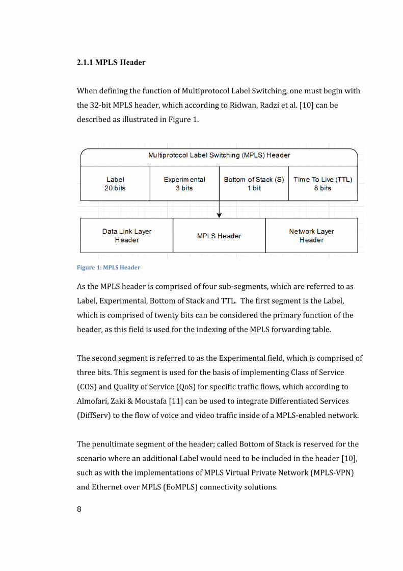
When defining the function of Multiprotocol Label Switching, one must begin with
the 32-bit MPLS header, which according to Ridwan, Radzi et al. [10] can be
described as illustrated in Figure 1.
Figure 1: MPLS Header
As the MPLS header is comprised of four sub-segments, which are referred to as
Label, Experimental, Bottom of Stack and TTL. The first segment is the Label,
which is comprised of twenty bits can be considered the primary function of the
header, as this field is used for the indexing of the MPLS forwarding table.
The second segment is referred to as the Experimental field, which is comprised of
three bits. This segment is used for the basis of implementing Class of Service
(COS) and Quality of Service (QoS) for specific traffic flows, which according to
Almofari, Zaki & Moustafa [11] can be used to integrate Differentiated Services
(DiffServ) to the flow of voice and video traffic inside of a MPLS-enabled network.
The penultimate segment of the header; called Bottom of Stack is reserved for the
scenario where an additional Label would need to be included in the header [10],
such as with the implementations of MPLS Virtual Private Network (MPLS-VPN)
and Ethernet over MPLS (EoMPLS) connectivity solutions.
9
The final segment of the header, referred to as the TTL field, is similar to the
equivalent field present in the IP header. The TTL field determines the lifecycle of
the MPLS header, which can be practically explained as a value that incrementally
decreases as the header interacts with other routers on the way to the destination.
[10] If this TTL value reaches zero, the packet and the header therein would be
discarded. The TTL value is assigned to ensure that the packet travels through the
specifically assigned path, such as to prevent any possible routing loops from
occurring within the MPLS network.
2.1.2 MPLS Label
In the function of the MPLS label there exists three different operations that can be
performed on the label: PUSH, SWAP and POP, which are performed on various
stages during the transmission of a packet throughout the network. For the
purposes of explaining the process of label manipulation, this document uses a
functionally simple network topology, which is visualized in Figure 2.
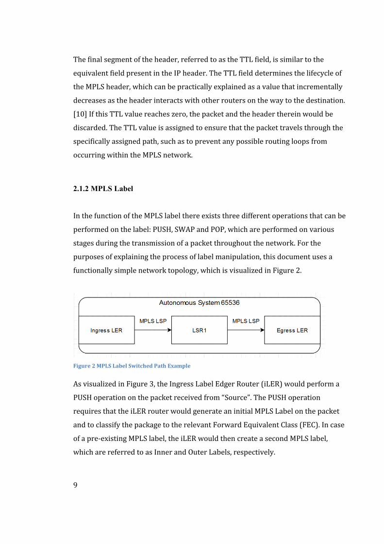
Figure 2 MPLS Label Switched Path Example
As visualized in Figure 3, the Ingress Label Edger Router (iLER) would perform a
PUSH operation on the packet received from “Source”. The PUSH operation
requires that the iLER router would generate an initial MPLS Label on the packet
and to classify the package to the relevant Forward Equivalent Class (FEC). In case
of a pre-existing MPLS label, the iLER would then create a second MPLS label,
which are referred to as Inner and Outer Labels, respectively.
10
The FEC is used to describe a group of packets that contain certain similarities,
such as an identical forwarding decision. FEC is assigned once at the network edge
at the Ingress-LSR router, such as that the packet will not require an additional
FEC assessment for each router the packet would cross on the way to the network
egress router (eLER). [6] Thus, the MPLS protocol achieves a significant efficiency
improvement when compared to the IP routing domain, as with traditional IP
routing the packet’s IP header would need to be examined with each router.
As the packet would travel through the MPLS domain, such as the route described
in Figure 3 on the route: “iLER – LSR1 – eLER”, the applicable Label Switched
Router (LSR) would then perform the SWAP operation on the LSR router, which
are denoted as “LSR1”. The SWAP operation would remove and replace the
existing MPLS label on the packet using the operations of POP and PUSH in the
respective order. In the case of multiple MPLS labels existing on the processed
packet, only the outermost label, thus being the more most recently added to the
specific packet, would be swapped with the new label.
The third operation is referred to as POP in which the MPLS label is removed from
the packet, which in Figure 3 would happen at the Egress-LER. The Egress-LER
would then remove the remaining MPLS header, and forward the aforementioned
packet based on the remaining destination address.
The removal of the MPLS label from such a package can be performed with two
distinct functions. In addition to the traditional method of removing the MPLS
label at the Egress LER, PHP or Penultimate Hop Popping can be used to drop the
MPLS label on penultimate hop before the eLER. [12]. This would be achieved with
the LER router advertising a label value of three, which equates to an implicit null.
The main discernible benefit of Penultimate Hop Popping is in the reduction of the
processing load on the LER router as it would only need to perform a label lookup
for the inner label, while simultaneously ignoring the outer label.
11
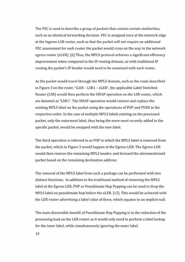
Figure 3 MPLS Forwarding Example
In order to illustrate the changes to the MPLS label during the travel between the
two ends of an IP/MPLS domain, Figure 3 visualizes the changes affecting the label
pushed onto a packet, which was sent for the router denoted as Destination.
Figure 3 is divided in to two distinct layers, with the topmost layer visualizing the
physical topology of the network, in addition to the status of the packet and the
MPLS Label assigned to the incoming packet. The bottom layer illustrates the MPLS
label manipulation actions that are performed by the Ingress and Egress Label
Edge Routers and the singular Label Switched Router in the illustrated topology.
2.1.3 Label Signaling
Considering the distribution of MPLS labels, the RFC 5036 authored by Andersson,
Minei & Thomas [7] was proposed in 2007 and implemented as the initial basis of
the Label Distribution Protocol or LDP in short. MPLS Label signalling can
additionally be implemented through the use of RSVP-TE (Resource Reservation
Protocol – Traffic Engineering), which will be covered in section 4.1.2 of this thesis.
The function of the LDP protocol relies on a foundation of peering relationships
between two distinct peers, which are formed through a discovery process, which
uses an “Hello” package sent using an UDP packet. [13] The UDP package is then
used to announce and uphold the network presence of a LSR router inside of the
IP/MPLS network.
12
Contrary to the discovery package, which uses UDP-based packets however, the
latter messages, namely the session, advertisement and notification messages
utilize a TCP-based transmission for their respective communications. The session
messages are used to note the changes in the LDP sessions that are formed
between the LSR routers, such as the deleting, changing, and creating such a
relationship between the communicating network nodes.
The advertisement messages are then used to modify label mappings to the
Forward Equivalence Classes (FEC), such as for the creation, modification, and the
deletion of these aforementioned label mappings inside the LSR routers. [13]
The decision to change the associated label and/or label mapping advertisements
are made by the local router when the label concerns the peering router, that is a
direct neighbour of the local router.
The notification messages are used to provide error notifications to the affected
LDP peer, such as in the case of a fatal software error. The relevant error
notification message is then used to close LDP session, with the simultaneous of
closure of the existing TCP connection. [13] Additionally, as the notification
package is used for an advisory notification, such as relaying information about a
previous message from a peer or about a certain LDP peering session. An advisory
notification would be transmitted for example in the case of a change that would
affect a MPLS LSP. There are multiple events that would cause an advisory
notification, such as an optical fibre break or a network router ecosystem failure.
In order to function properly, the Label Distribution Protocol requires the function
of an Internal Gateway Protocol (IGP) such as Open Shortest Path First (OSPF) or
Intermediate System-to-Intermediate System (IS-IS). The synchronization of the
IGP and LDP is required according to Juniper Networks [13] as the threat of packet
loss occurs without such synchronization, especially in scenarios where the core
segment of the IP/MPLS network does not employ iBGP.
13
2.1.4 Label Switched Paths
Label Switched Paths can be divided into two different archetypes depending on
the nature of their configuration. The first archetype, referred to as the Static LSP
is a solution where LSP path is determined manually, thus mitigating the need for a
signalling protocol such as the Label Distribution Protocol (LDP) or Resource-
Reservation Protocol (RSVP) to be active on that specific LSP.
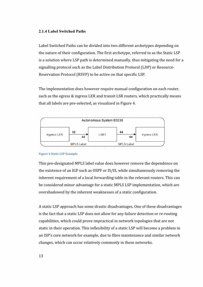
The implementation does however require manual configuration on each router,
such as the egress & ingress LER and transit LSR routers, which practically means
that all labels are pre-selected, as visualized in Figure 4.
Figure 4 Static LSP Example
This pre-designated MPLS label value does however remove the dependence on
the existence of an IGP such as OSPF or IS/IS, while simultaneously removing the
inherent requirement of a local forwarding table in the relevant routers. This can
be considered minor advantage for a static MPLS LSP implementation, which are
overshadowed by the inherent weaknesses of a static configuration.
A static LSP approach has some drastic disadvantages. One of these disadvantages
is the fact that a static LSP does not allow for any failure detection or re-routing
capabilities, which could prove impractical in network topologies that are not
static in their operation. This inflexibility of a static LSP will become a problem in
an ISP’s core network for example, due to fibre maintenance and similar network
changes, which can occur relatively commonly in these networks.
14
These network topology changes can occur due reasons such as a municipal road
construction, IRU lease termination, PoP (Point of Presence) decommissioning and
critical failures in the routers present on the path of the statically configured LSP,
such those caused by a sudden power outage or router ecosystem failure, which
can be related to either to the hardware or the software of the IP/MPLS router.
The second archetype, referred to as the signalled LSP which allows for a dynamic
approach to LSPs, as the setup of a signalled LSP utilizes either the LDP protocol or
the more recent RSVP-TE (RSVP - Traffic Engineering) protocol extension.
As this approach only requires manual configuration on the Ingress & Egress Label
Edge Routers, the process allows for the automatic assignment of labels from
ingress to the egress routers. This approach is dependent on existence of an IGP
(e.g., OSPF & IS/IS) and a local forwarding table, which does introduce an
additional critical dependency to the beforementioned forwarding table.
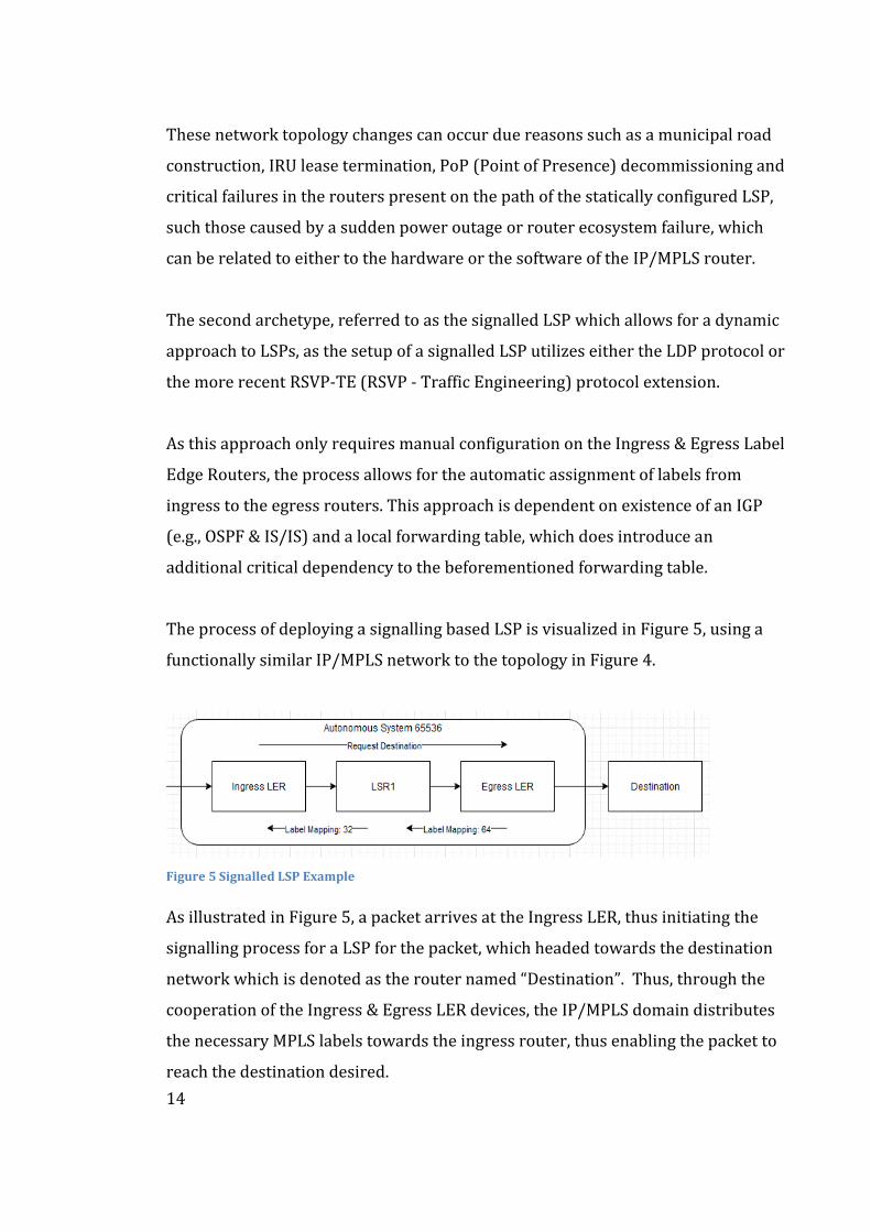
The process of deploying a signalling based LSP is visualized in Figure 5, using a
functionally similar IP/MPLS network to the topology in Figure 4.
Figure 5 Signalled LSP Example
As illustrated in Figure 5, a packet arrives at the Ingress LER, thus initiating the
signalling process for a LSP for the packet, which headed towards the destination
network which is denoted as the router named “Destination”. Thus, through the
cooperation of the Ingress & Egress LER devices, the IP/MPLS domain distributes
the necessary MPLS labels towards the ingress router, thus enabling the packet to
reach the destination desired.
15
2.1.5 Evolution of MPLS
As MPLS networks developed and increased in complexity, multiple new
extensions, and variants of the baseline MPLS technology were developed, of
which we will introduce three examples: G-MPLS, MPLS-TE and MPLS-TP.
G-MPLS, or Generalised Multiprotocol Label Switching, as defined in the RFC
3945 authored by E. Mannie [14] was introduced as an extension to the original
MPLS architecture as defined in RFC 3031 by Rosen et al [2]. The primary purpose
of the G-MPLS extension is to enable the integration of network elements such as
Dense Wavelength-Division Multiplexing (DWDM), which often reside in optical
cross connects (OXCs) and Time-Division Multiplexing (TDM) systems into the
baseline MPLS architecture. According to Mannie [14], this optical system
integration increases the survivability of the IP/MPLS-based network and allows
for the dynamic provision of network resources.
Additionally, G-MPLS introduces a scalable hierarchy to the Label Switched Paths
used by the heterogenous network devices, such as with the traditional IP/MPLS
routers and optical elements such as WDMs and Synchronous Optical Hierarchy
(SDH) systems. The LSP Hierarchy is as follows from the top downwards,
according to Iovanna et al. [15]: Fibre, Lambda (λ), TDM, Layer 2 and Packet.
MPLS-TE, or Multiprotocol Label Switching - Traffic Engineering allows for the
introduction of traffic route engineering into the MPLS architecture to ease
network congestion. This is highly desirable in the networks of Internet Service
Providers as multiple delay-sensitive systems are often governed by both Quality
of Service (QoS) requirements and strict Service Level Agreements (SLA). The
controls added by MPLS-TE can be used in varied ways in ISP networks, such as
with adding a prioritization value to a group of LSP’s at the header, which would
indicate to the LSR which of the LSP’s is to be considered of greater value to them.
16
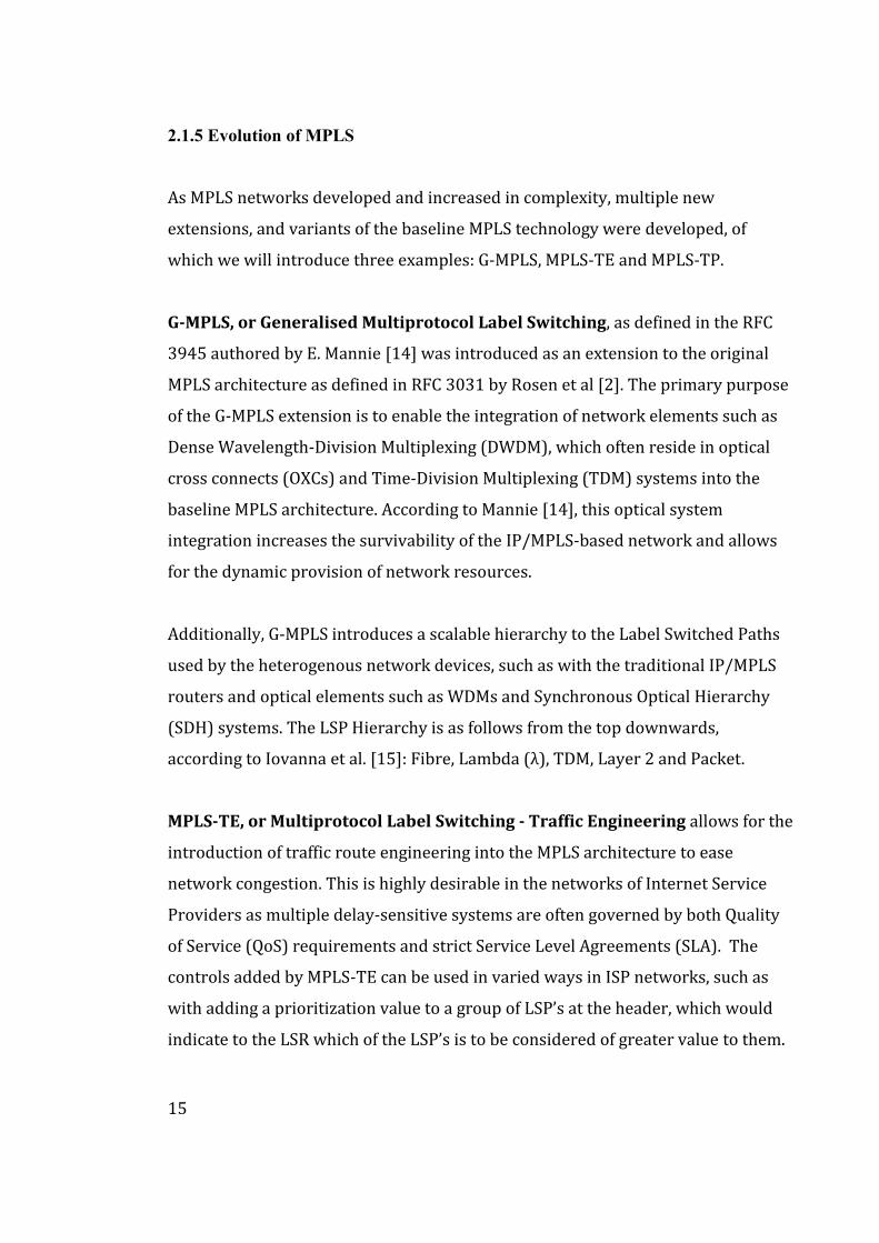
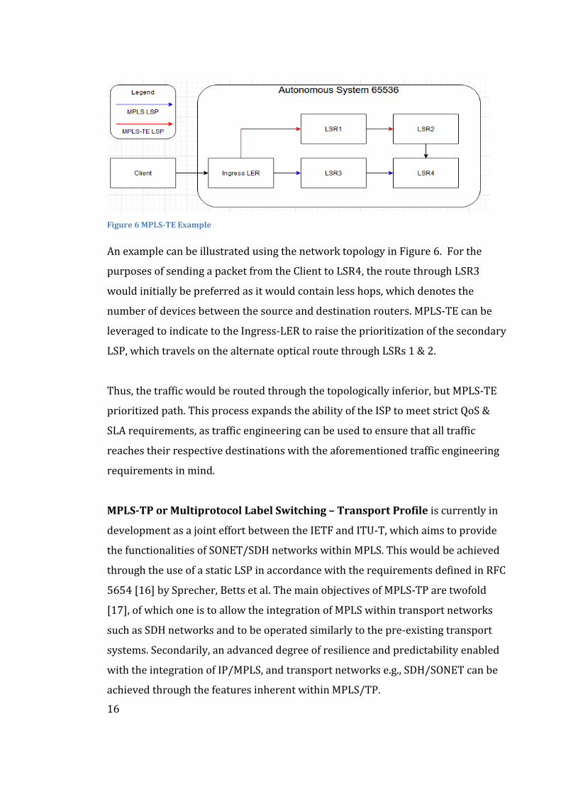
Figure 6 MPLS-TE Example
An example can be illustrated using the network topology in Figure 6. For the
purposes of sending a packet from the Client to LSR4, the route through LSR3
would initially be preferred as it would contain less hops, which denotes the
number of devices between the source and destination routers. MPLS-TE can be
leveraged to indicate to the Ingress-LER to raise the prioritization of the secondary
LSP, which travels on the alternate optical route through LSRs 1 & 2.
Thus, the traffic would be routed through the topologically inferior, but MPLS-TE
prioritized path. This process expands the ability of the ISP to meet strict QoS &
SLA requirements, as traffic engineering can be used to ensure that all traffic
reaches their respective destinations with the aforementioned traffic engineering
requirements in mind.
MPLS-TP or Multiprotocol Label Switching – Transport Profile is currently in
development as a joint effort between the IETF and ITU-T, which aims to provide
the functionalities of SONET/SDH networks within MPLS. This would be achieved
through the use of a static LSP in accordance with the requirements defined in RFC
5654 [16] by Sprecher, Betts et al. The main objectives of MPLS-TP are twofold
[17], of which one is to allow the integration of MPLS within transport networks
such as SDH networks and to be operated similarly to the pre-existing transport
systems. Secondarily, an advanced degree of resilience and predictability enabled
with the integration of IP/MPLS, and transport networks e.g., SDH/SONET can be
achieved through the features inherent within MPLS/TP.
17
2.2 BGP, Border Gateway Protocol
The Border Gateway Protocol (BGP) is the de-facto routing protocol in the
communications between different Autonomous Systems across the world, which
exchange reachability information through the interconnections between these
networks. The BGP protocol is concurrently defined in RFC 4271 by Rekhter, Li &
Hares [18], although multiple updates, proposals and revisions exist within various
IETF Request for Comments-documents.
In the ISP network space, these interconnects are often governed by peering
agreements, where the transit of data between two or more Autonomous Systems
is legislatively and commercially formalized. These are not the only interconnects
that exist between ISPs, as implementations such as a NNI (Network-To-Network
Interface) and PNI (Private Network Interconnect) are used to manage and define
signalling between two distinct and complex Autonomous Systems.
2.2.1 Foundations of BGP
BGP utilizes two router roles as the protocol’s operational basis, which are
referred to as a BGP speaker and a BGP peer. The speaker role is comprised of any
and all routers that receive or generate routing information, thus propagating the
information throughout the network. If the router would receive a router from an
another AS, the received route would be compared to the local route table to
determine whether to propagate the received route.
The peer role refers to all BGP routers, including speakers, that exchange messages
with each other either through direct connections or Multihop sessions, where the
underlying route must be installed to the RIB (Routing Information Database) in
order to establish the required TCP-based connection between these in-directly
connected routers. [19]
18
The overall function of BGP relies on the propagation of five messages, which are
referred to as Open, Update, Notification, Keepalive and Route-Refresh.
An Open message is to be sent when an TCP-based connection and the associated
three-way handshake are completed, thus causing the router’s state to transfer to
OpenSent. These Open messages contain the following information including the
associated BGP header: BGP Version (i.e., 4), Local AS Number (i.e., AS1234), Hold
Time (i.e., 30 seconds), BGP Identifier (i.e., Interface IP address or RouterID) and
various optional fields such as the parameter field & parameter length fields. [19]
The Update message is used provide reachability information across the network
when changes in connectivity e.g., introduction of new connections occurs. These
messages can contain the following information [19]: Length of the withdrawn
route, any and all prefixes that have been withdrawn due to unreachability, the
total attribute length which demonstrates the path of a feasible route to a
destination, the NLRI (Network Layer Reachability Information) that contains
prefixes for the previously mentioned feasible routes and the path attributes (i.e.,
route reflection & the MED (Multiple Exit Discriminator).
The Keepalive message is used to ascertain whether or not a peering router and/or
link has ceased to function, through a continuous effort of exchanging Keepalive
messages. Should a router fail to respond to these requests, hold time negotiated in
the Open message exchange would expire, thus triggering a Notification message.
In the aforementioned scenario, Notification messages would be used should the
router fail to respond to the requests of the Keepalive message, thus indicating an
error in the connectivity. Thereafter, the router would then send a notification
message, which includes both variants of the error code (main and sub) and
inclusionary data that describes the associated error. The process of sending a
notification message initiates the closure of the associated BGP session and the
TCP connection between the previously peering routers.
19
Route Refresh is reserved for situations where the router has received an
advertisement concerning the availability of a refresh capability, which is strictly
required for BGP operation. This message has two distinct uses:
- Request a BGP route update (Dynamic or inbound)
- Propagate a BGP route update to an existing BGP peer.
Through the use of these previously mentioned messages, the BGP-enabled routers
will go through multiple phases referred to as states, differentiated by the BGP
FSM (Finite State Machine). The first of these phases is the Idle state, where the
BGP peers try to initiate a TCP connection, which would then initiate the transfer
to the Connect phase after the necessary signalling have been completed.
In the Connect state, the initiation of a BGP session begins with a three-way-
handshake. After a successful handshake, the router would then initiate the
procurement of an Open message from the remote peer, while simultaneously
transferring the router to the OpenSent state. Should this handshake fail however,
the router would return to the Active state where the handshake will be retried. If
this second handshake would fail, the routers would then return to the Idle state.
In the OpenSent state the routers will wait for an Open message from the remote
peer. After such a message has arrived, it will be checked for errors such as a faulty
AS identifier (ASN) or a BGP version mismatch. If the received message does not
contain errors, the router would then send continuous Keepalive messages to the
remote peer, thus simultaneously transitioning to the OpenConfirm state.
After both routers have received the Keepalive messages, the BGP session is
considered complete thus being referred to as Established. In this state, the routers
will then exchange routing information through Update messages and send a
continuous stream of Keepalive messages in order to maintain the newly-
established BGP session.
20
2.2.2 BGP Operation
Autonomous Systems, which are continuous networks that are administrated by a
single entity are the foundation that BGP relies upon for inter-AS communication.
These independent networks are identified from each other through the use of an
ASN (Autonomous System Number), such as the AS16086 which denotes the
network operated by the benefactor of this thesis, DNA Plc.
These ASN values, which are distributed by Regional Internet Registries such as
the European RIPE NCC, were originally limited to the number of values in a 16-bit
integer (0 - 65534), with some specific numbers reserved for documentation
purposes. To further increase the amount of available ASN identifiers, the
implementation of a 32-bit integer was introduced with the RFC 6793 by Vohra &
Chen [20], which allowed for the assignment of over 4,2 billion distinct ASNs.
The primary use case for BGP exists between these Autonomous Systems as an
eBGP application, it can also be used as an IGP similarly to the OSPF and RSVP.
In larger networks such an implementation often requires the implementation of
RR (route reflector) routers which significantly reduces the amount of BGP
sessions to required to fulfil the full-mesh model requirement.
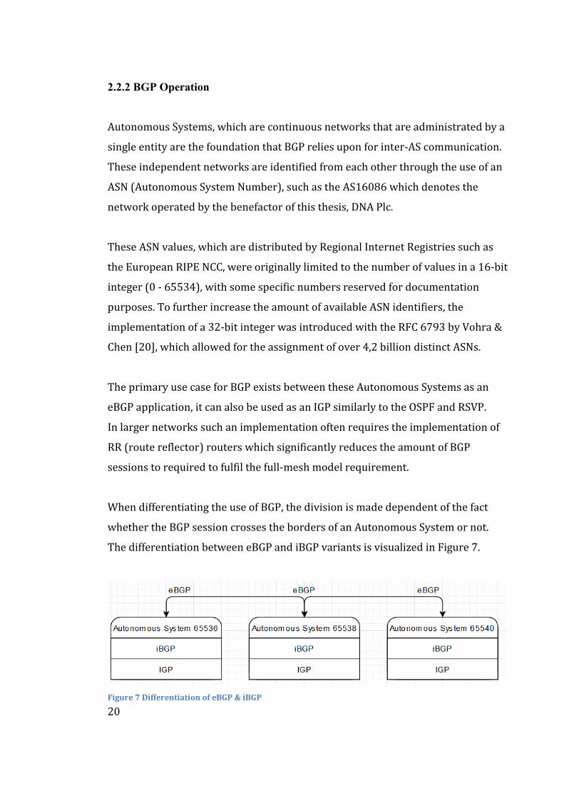
When differentiating the use of BGP, the division is made dependent of the fact
whether the BGP session crosses the borders of an Autonomous System or not.
The differentiation between eBGP and iBGP variants is visualized in Figure 7.
Figure 7 Differentiation of eBGP & iBGP
21
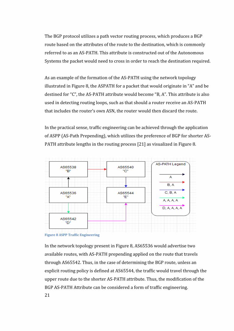
The BGP protocol utilizes a path vector routing process, which produces a BGP
route based on the attributes of the route to the destination, which is commonly
referred to as an AS-PATH. This attribute is constructed out of the Autonomous
Systems the packet would need to cross in order to reach the destination required.
As an example of the formation of the AS-PATH using the network topology
illustrated in Figure 8, the ASPATH for a packet that would originate in “A” and be
destined for “C”, the AS-PATH attribute would become “B, A”. This attribute is also
used in detecting routing loops, such as that should a router receive an AS-PATH
that includes the router’s own ASN, the router would then discard the route.
In the practical sense, traffic engineering can be achieved through the application
of ASPP (AS-Path Prepending), which utilizes the preference of BGP for shorter AS-
PATH attribute lengths in the routing process [21] as visualized in Figure 8.
Figure 8 ASPP Traffic Engineering
In the network topology present in Figure 8, AS65536 would advertise two
available routes, with AS-PATH prepending applied on the route that travels
through AS65542. Thus, in the case of determining the BGP route, unless an
explicit routing policy is defined at AS65544, the traffic would travel through the
upper route due to the shorter AS-PATH attribute. Thus, the modification of the
BGP AS-PATH Attribute can be considered a form of traffic engineering.
22
2.2.3 BGP Route Processing
In operational terms, BGP processes each prefix in their respective routing tables
in order to perform active path selection. This process is based on preference
values which are additionally referred to as administrative distance value.
The BGP route selection mechanism is broken down as follows according to
Juniper Networks [19]:
- Verify that next-hop can be resolved.
- Lowest preference value (Protocol process preference)
- Choose the path with the highest local preference value, where non-BGP
associated paths will use the “preference_2” value.
- If enabled, prefer the route with the lower AIGP attribute.
- Prefer the shortest AS-PATH, where a single AS is valued as one and BGP
confederations are valued as zero.
- Prefer the lower Origin code, where routes learned for IGPs have a value
lower than routes learned though an EGP.
- Prefer the lowest MED (Multiple Exit Discriminator) metric
- Prefer internal routes, such as those strictly learned from an IGP (e.g.,
OSPF) or statically configured routes.
- Prefer external routes, strictly learned from external paths such as from an
internal iBGP.
- Prefer the route with the lower IGP metric, such as OSPF cost.
- Prefer the active path, should both paths be external as to avoid
unnecessary route-flapping.
- Prefer the primary path, choosing a route from the routing table over one
added by an export policy.
- Prefer the lower Router ID.
- Prefer the shortest Cluster ID.
- As the ultimate tiebreaker, prefer the lower peer IP address.
23
2.2.4 Implementations of BGP
Within the networks of Internet Service Providers multiple implementations and
advanced features of BGP are used, such as for iBGP network scaling optimization.
Optimization measures, such as the use of RR (Route Reflector)-devices and BGP
Confederations, of which the latter allows the division of the ISP’s primary
Autonomous System into various sub-sections. Additionally, traffic engineering
solutions that manipulate BGP route propagation can be implemented through the
use of BGP Communities. These communities are used to modify and/or limit the
propagation of BGP advertisements, thus allowing for a dynamic routing policy.
Route Reflectors, as defined in RFC 4456 by Bates, Chen & Chandra [22] are
specialized routers, that are used to reduce the amount of required BGP sessions in
the network. Due to requirements inherent in the BGP protocol, a full mesh must
be implemented, therefore requiring all BGP participants to talk to each other.
These full-mesh BGP sessions are managed through the use of manual
configurations, thus the number of configurations per network change (e.g.,
addition/removal of a router) exponentially increases the amount of configuration
changes needed in addition to the increased processing load placed on the network
itself. As such, the full-mesh requirement would prove impractical in large
IP/MPLS networks that employ iBGP, such as those operated by an ISP.
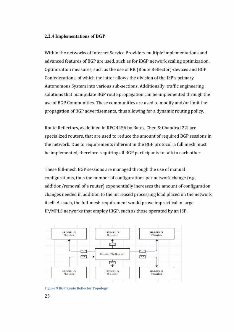
Figure 9 BGP Route Reflector Topology
24
As visualized in Figure 9, the usage of a route reflector would reduce the amount of
the required BGP sessions from the full-mesh requirement that follows the formula
of “N(N-1)/2” which in the specified scenario would require six BGP sessions to
fulfil the requirement of the full-mesh implementation. Through the use of a route
reflector, the aforementioned topology can be achieved with only 4 BGP sessions
towards the RR-device, thus improving the efficiency by 33 %. This perceived
improvement will scale exponentially as the number of devices within the network
increases, therefore increasing the BGP efficiency of the network overall.
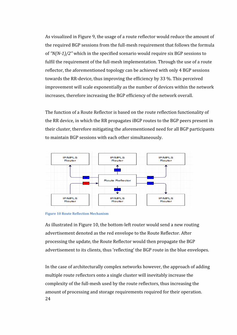
The function of a Route Reflector is based on the route reflection functionality of
the RR device, in which the RR propagates iBGP routes to the BGP peers present in
their cluster, therefore mitigating the aforementioned need for all BGP participants
to maintain BGP sessions with each other simultaneously.
Figure 10 Route Reflection Mechanism
As illustrated in Figure 10, the bottom-left router would send a new routing
advertisement denoted as the red envelope to the Route Reflector. After
processing the update, the Route Reflector would then propagate the BGP
advertisement to its clients, thus ‘reflecting’ the BGP route in the blue envelopes.
In the case of architecturally complex networks however, the approach of adding
multiple route reflectors onto a single cluster will inevitably increase the
complexity of the full-mesh used by the route reflectors, thus increasing the
amount of processing and storage requirements required for their operation.
25
Thus, the implementation of a hierarchical route reflection can be used to offset
the problem, which requires at least two layers of route reflectors. The first layer is
the core RR network, which forms a distinct cluster i.e., Cluster 1, while the second
layer consists of route reflectors which are simultaneously part of sub-clusters
such as Clusters 2,3 and 4 in addition to Cluster 1. The full-mesh requirement
would only concern the RR-devices strictly in Cluster 1, thus reducing the amount
of required full-mesh deployments as the double-clustered RRs i.e., routers that
exist in both clusters one & two, are not required to maintain the full routing table.
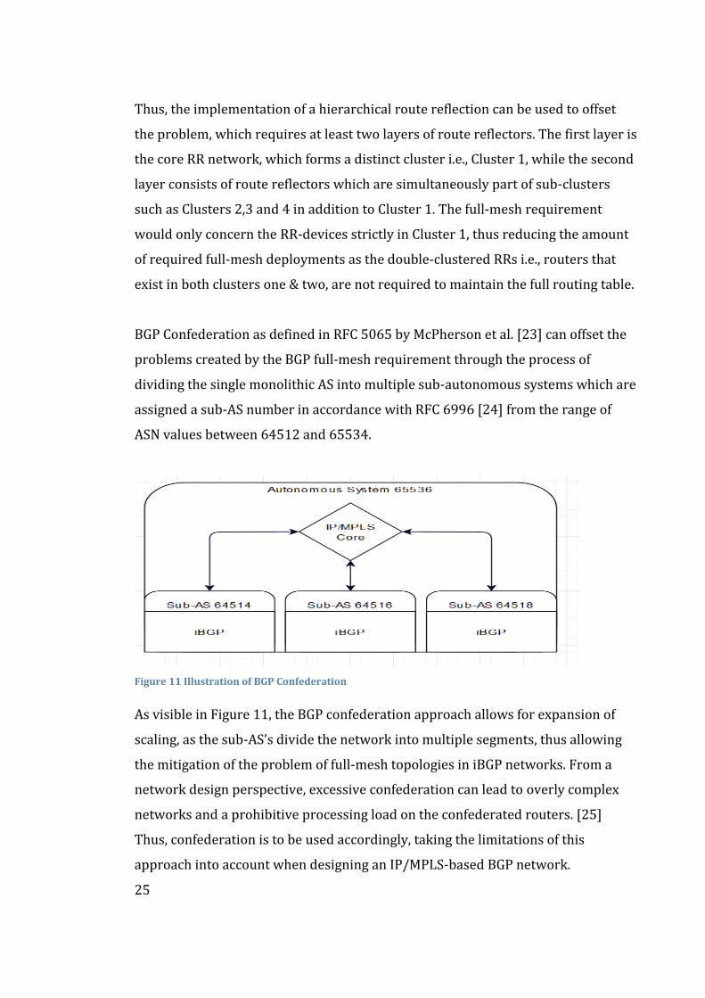
BGP Confederation as defined in RFC 5065 by McPherson et al. [23] can offset the
problems created by the BGP full-mesh requirement through the process of
dividing the single monolithic AS into multiple sub-autonomous systems which are
assigned a sub-AS number in accordance with RFC 6996 [24] from the range of
ASN values between 64512 and 65534.
Figure 11 Illustration of BGP Confederation
As visible in Figure 11, the BGP confederation approach allows for expansion of
scaling, as the sub-AS’s divide the network into multiple segments, thus allowing
the mitigation of the problem of full-mesh topologies in iBGP networks. From a
network design perspective, excessive confederation can lead to overly complex
networks and a prohibitive processing load on the confederated routers. [25]
Thus, confederation is to be used accordingly, taking the limitations of this
approach into account when designing an IP/MPLS-based BGP network.
26
BGP Communities, as defined in RFC 1997 [26] can be utilized for applications
such as BGP routing policy management, traffic engineering, BGP advertisement
propagation filtering.
Well-known examples of such BGP communities as defined in RFC 1997, are the
“NO_EXPORT” and “NO_ADVERTISE” communities. The foremost community
disallows the advertisement of the given route outside of the limits of a BGP
confederation, while the latter community forbids the advertisement of the routes
to any and all other BGP peers, aside from the direct peer for the sending AS.
This mechanism leverages the optional 32-bit community BGP attribute to add a
tag, which is denoted as “AS:Tag” e.g., AS65536:1871 to a route advertisement.
This tag is then used to label groups of prefixes for specific purposes, such as
limiting the advertisement of the associated prefixes to remain strictly inside the
European Union or to avoid a certain Autonomous System.
A network operator may choose to announce their accepted communities publicly,
such as to increase the adoption of a community that would modify the
LOCAL_PREF attribute to a specific value, such as AS6667:100 used by the Elisa
Corporation [27], which modifies the aforementioned attribute to the value of 100.
For the purposes of traffic engineering, the usage of a blackhole community tag,
often denoted ‘666’ as specified in RFC 7999 [28], can be used to mitigate the
threat of a DDOS (Distributed Denial of Service) attack. This mitigation is achieved
through attaching the blackhole BGP community tag to the affected prefix, which
indicates that the receiving AS should drop all traffic with this specific prefix.
A similar method of traffic engineering can be achieved should network operator
choose to filter out BGP communities at the network border it considers harmful,
such as filtering out prefixes longer than /24 or the IP address blocks that are
reserved by the Internet Assigned Numbers Authority (IANA) organization.
27
2.2.5 Evolution of BGP
M-BGP, Multiprotocol Extensions for BGP defined in RFC 4760 by Bates, Katz,
Chandra et al. [29] allows for the expansion of the BGP protocol by introducing the
ability to transmit routing information through various routing protocols e.g., IPv6
& L3VPN, in addition to allowing the propagation of multicast routing information.
The addition of multicast routing capability does however require the separation
of routing tables, as the concurrent BGP protocol does not support multicast.
Thus, M-BGP forms a distinct and strictly separate multicast routing topology
which is then used in parallel with the pre-existing unicast routing table.
In the networks of Internet Service Providers, M-BGP can be used to implement
load balancing for multiple inter-domain routes that share an equal cost. In
practise, M-BGP utilizes multiple installations of an active path instead of resolving
the best route through the traditional tiebreaker of last-resort.
When considering a more commercial use case, the utilization of M-BGP in the
implementation of MPLS VPN’s, which are used to enable connectivity for
customers connected to the IP/MPLS backbone. This approach enables traffic flow
separation as each distinct VPN route has a unique VRF (Virtual Routing and
Forwarding) instance. In the aforementioned scenario, M-BGP is used as the
transmission carrier for the Reachability Information.
The VRF is utilized to implement multiple distinct routing tables on the PE
(Provider Edge) devices, from which the traffic is carried through the IP/MPLS
core network in an encapsulated form. The traffic is then carried to the specific CE
router at the other end of the MPLS VPN tunnel, such as a customer’s second
premises. This approach would enable the separation of the traffic that would
travel throughout the IP/MPLS core transmission network, therefore increasing
the overall security and privacy of the traffic therein.
28
2.3 OSPF, Open Shortest Path First
OSPF, Open Shortest Path First is a hierarchical routing protocol, which can be
utilized as an IGP (Internal Gateway Protocol) in an IP/MPLS-based ISP network,
in addition to technologies such as IS-IS. The overall function of OSPF is defined in
RFC 2328 by Moy [30] and RFC5340 by Coltun, Ferguson, Moy & Lindem [31], for
versions designed for IPv4 and IPv6, respectively.
The development of OSPF can be traced back to the late 1980’s where the
problems associated with the use of RIP (Routing Information Protocol), e.g.,
limitation of fifteen hops and the slow convergence of routes across the network.
Additionally, the inherent inefficiency of RIP operation, the thirty second
broadcast, hinders the scalability of the protocol in conjunction with the 15-hop
limit. Thus, a more efficient, scalable, and resilient protocol was needed.
Thus, with the incremental updates made to the OSPF protocol, the most recent
IETF standard was proposed in 1998. The aforementioned version 3, often
referred to as OSPFv3. OSPFv3 allows for the support of IPv6 protocol addressing
within OSPF was proposed in 2008 but has not yet achieved full standardization as
RFC5340 is still considered a “Proposed Standardization” by the IETF. Regardless,
extensive support for the use of OSPFv3 is provided by multiple networking
hardware vendors such as Juniper Networks and Cisco Systems.
Within an Autonomous System, such as the AS719 operated by the Elisa
Corporation, OSPF is often used as link-state protocol, which governs internal
routing solutions made within the network. These routing solutions are based on a
SPF (Shortest Path First) algorithm that governs the route selection process.
Thus, as OSPF operates at a link-state level, it is often used in conjunction with an
implementation of an iBGP, or an internal Border Gateway Protocol. This dual
protocol approach is often implemented within ISP networks alongside MPLS.
29
2.3.1 Forming an OSPF Network
The function of OSPF relies on the previously mentioned SPF algorithm, which
relies upon a value assigned to a network link between two devices within a
network, which is referred to as an OSPF cost or an OSPF metric, depending on the
context. This metric could be either determined through the use of the Shortest
Path First (SPF) algorithm, which is based on either Dijkstra’s algorithm or
manually configured, should a network operator wish to employ purposeful traffic
engineering in their OSPF-enabled network. [32]
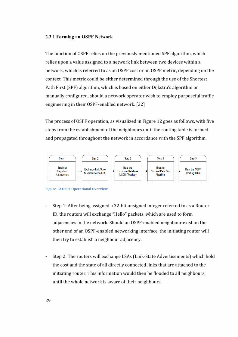
The process of OSPF operation, as visualized in Figure 12 goes as follows, with five
steps from the establishment of the neighbours until the routing table is formed
and propagated throughout the network in accordance with the SPF algorithm.
Figure 12 OSPF Operational Overview
- Step 1: After being assigned a 32-bit unsigned integer referred to as a Router-
ID, the routers will exchange “Hello” packets, which are used to form
adjacencies in the network. Should an OSPF-enabled neighbour exist on the
other end of an OSPF-enabled networking interface, the initiating router will
then try to establish a neighbour adjacency.
- Step 2: The routers will exchange LSAs (Link-State Advertisements) which hold
the cost and the state of all directly connected links that are attached to the
initiating router. This information would then be flooded to all neighbours,
until the whole network is aware of their neighbours.
30
- Step 3: The routers use the available LSAs to generate a topology database,
which is referred to as a LSDB (Link-State Database), or in specific
circumstances as the Topology Table. The newly created LSDB database can
contain multiple identifying data sets such as the IP address or network mask
of the connected interface.
- Step 4: After the LSDBs have been formed throughout the network, the
associated routers will then begin processing the information through the use
of the SPF algorithm. Thereafter, the SPF algorithm would create a SPF Tree,
which would contain all available routes for the specific OSPF-enabled router.
- Step 5: The routers will then insert the best routes into the routing table in
accordance with the calculated cost of the route. Should any LSAs be missing a
record, the affected router would then perform a Link-State-Request (LinkSR)
which would then ask for the associated records from others. [33] Afterwards,
the router would receive a Link-Status Update (LSU) which would contain the
necessary details on the requested missing LSA.
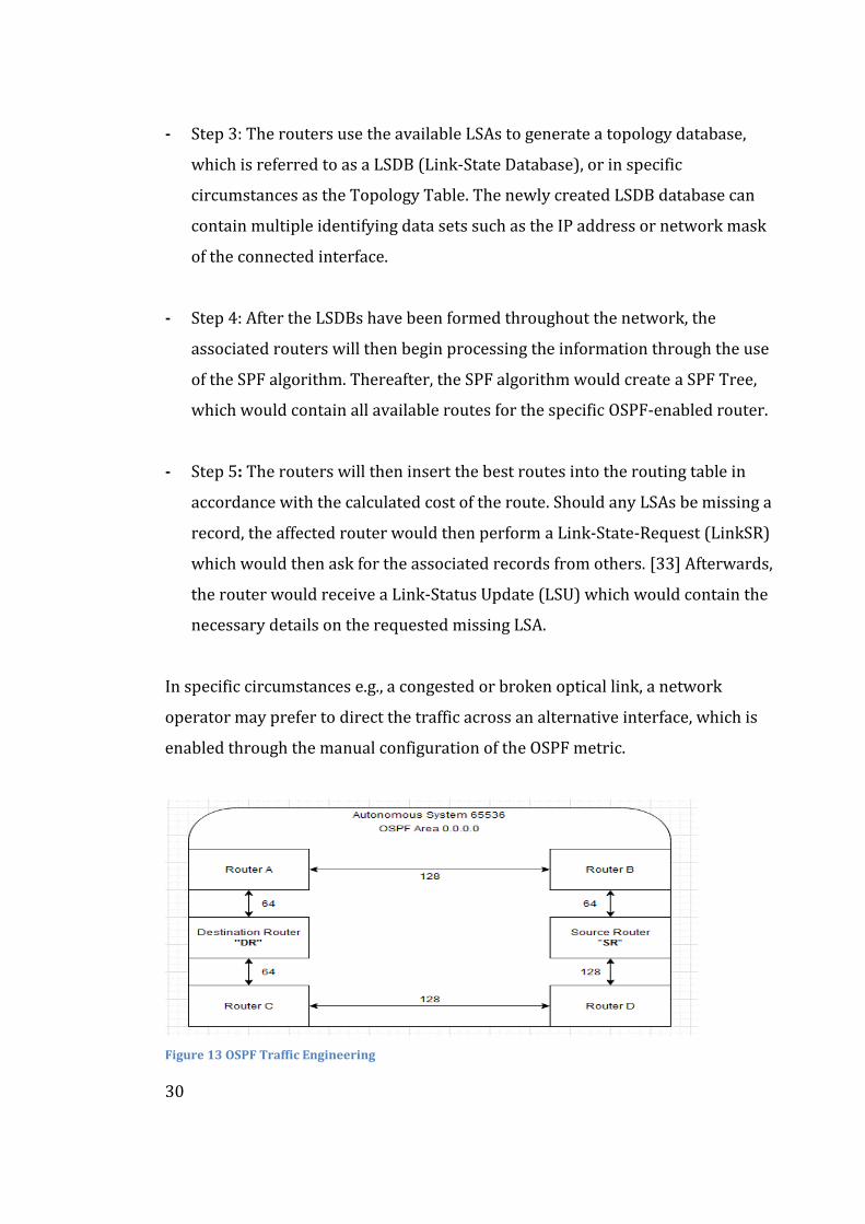
In specific circumstances e.g., a congested or broken optical link, a network
operator may prefer to direct the traffic across an alternative interface, which is
enabled through the manual configuration of the OSPF metric.
Figure 13 OSPF Traffic Engineering
31
As illustrated in topology of Figure 13, the premise is to send a packet from the
Source Router (SR) to the Destination Router (DR) with manually configured OSPF
metric per network interface. The SR has two optical routes to reach the DR, thus
the SR would compare the route metrics of these two routes. The cost of travelling
through the route through Routers D and C would have an OSPF cost of 320, while
the route traversing through Routers B and A have combined OSPF cost of 256.
Thus, the SR would choose to use the upper route due to the lower OSPF metric.
The process therein suggests that the route that has the lowest calculated metric
will be chosen as the best route, which will be then added to the routing table. This
cost is often based on the interface link speed e.g., a 400 GB/s link would gain a
lower OSPF metric when compared to a 100 GB/s link.
For the purposes of essentially shutting down traffic between the link on Routers A
& B in Figure 13, the network operator would set an abnormally high OSPF metric,
such as the maximum value of 65535, on the specific optical link. This traffic
engineering method allows a network operator to minimize the amount of affected
network traffic on a specific router during a scheduled maintenance, as such a high
OSPF metric would effectively steer traffic away from the affected interface.
Using the network topology of Figure 13 as an example, should a network operator
wish to perform maintenance on Router B, they would reconfigure the OSPF metric
between Routers A and B to the aforementioned value of 65535. The reconfigured
metric would effectively force the traffic to travel through the redundant optical
link which travels through Router D, while simultaneously draining the traffic from
the original optical link.
Thus, after initializing the maintenance process, such as a router software upgrade,
only the traffic headed for Router B would be affected, which allows the rest of the
network to function without unnecessary SLA-service impact. Thus, an overall
improvement to the customer connectivity can be accomplished with this process.
32
2.3.2 Function of OSPF
As the complexity of the link-state database will increase with every additional
router that is connected to a singular OSPF network, therefore increasing the
processing load on the associated routers. Adding multiple new routers within the
same network would then create a complex and time-consuming computational
process for the routers as they would take heed of all of its neighbours within the
same OSPF area, thus increasing the amount of delay before route convergence.
If the entire network of an Internet Service Provider would be configured within a
singular OSPF area, the number of routes a singular router would need to know
would increase exponentially as these networks often contain hundreds or even
thousands of routers and various other devices. Such a large number of devices
belonging to a singular OSPF area would cause long convergence times and
“network storms” of traffic flow. These “storms” would occur after a network
change as the entire network would update their LSDB’s simultaneously.
To avoid this specific problem, the OSPF network is often divided into subsections,
which are referred to as OSPF areas. These areas form subsections, that can be
divided up through various methods, such as with the geographical location of the
routers. As an example, the routers in the vicinity of a city such as Frankfurt am
Main could belong to an OSPF area with the address of 8.8.8.8, while the routers
near the city of Strasbourg could belong to an OSPF area of 7.7.7.7 for example.
Traditionally, the core network, otherwise known as the backbone area, is
assigned to be the Area 0, which in the Juniper Networks devices is assigned
through the command: “set protocols ospf area 0.0.0.0 interface “interface port”.
The routers therein would strictly belong to the backbone area, with one specific
exception which are the routers that function as Area Border Routers (ABRs).
ABRs enable the interarea communication between separate OSPF areas, thus
cementing their architecturally critical role in an OSPF-enabled IP/MPLS network.
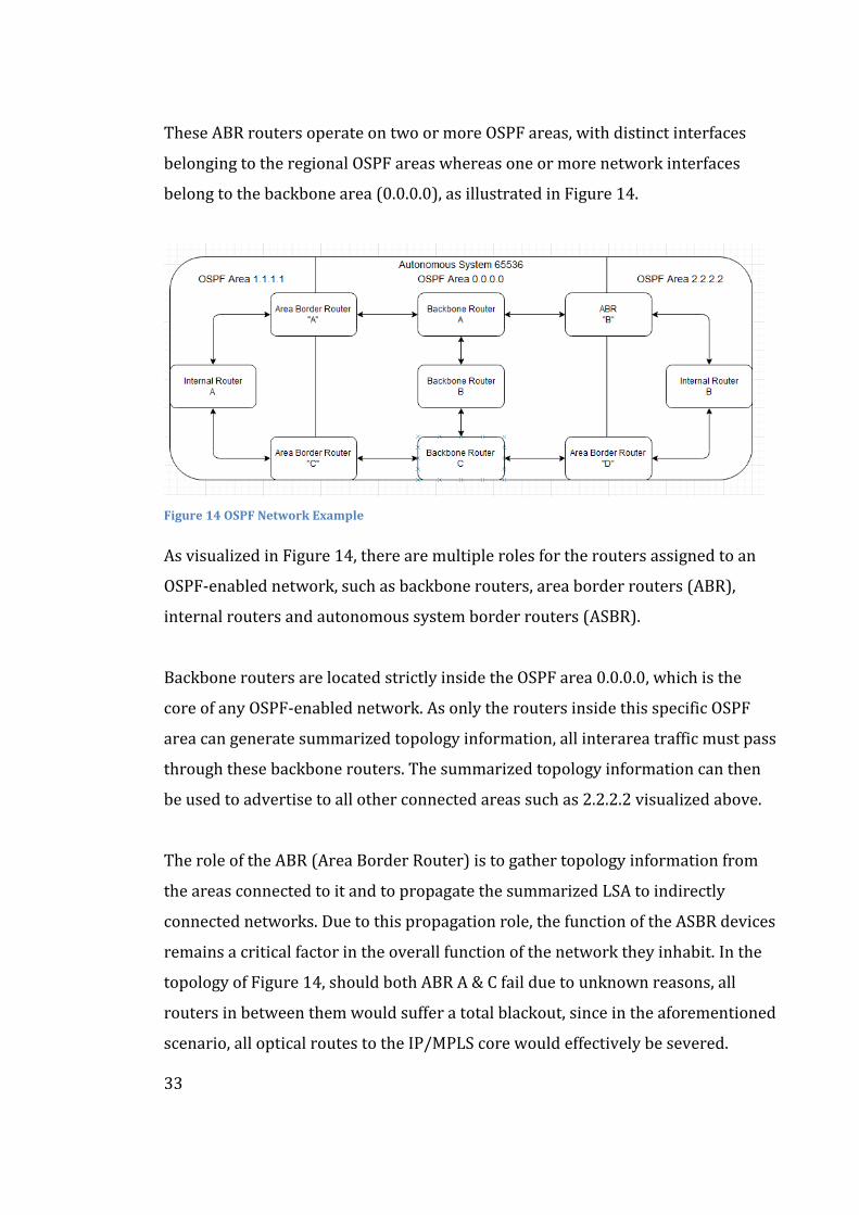
33
These ABR routers operate on two or more OSPF areas, with distinct interfaces
belonging to the regional OSPF areas whereas one or more network interfaces
belong to the backbone area (0.0.0.0), as illustrated in Figure 14.
Figure 14 OSPF Network Example
As visualized in Figure 14, there are multiple roles for the routers assigned to an
OSPF-enabled network, such as backbone routers, area border routers (ABR),
internal routers and autonomous system border routers (ASBR).
Backbone routers are located strictly inside the OSPF area 0.0.0.0, which is the
core of any OSPF-enabled network. As only the routers inside this specific OSPF
area can generate summarized topology information, all interarea traffic must pass
through these backbone routers. The summarized topology information can then
be used to advertise to all other connected areas such as 2.2.2.2 visualized above.
The role of the ABR (Area Border Router) is to gather topology information from
the areas connected to it and to propagate the summarized LSA to indirectly
connected networks. Due to this propagation role, the function of the ASBR devices
remains a critical factor in the overall function of the network they inhabit. In the
topology of Figure 14, should both ABR A & C fail due to unknown reasons, all
routers in between them would suffer a total blackout, since in the aforementioned
scenario, all optical routes to the IP/MPLS core would effectively be severed.
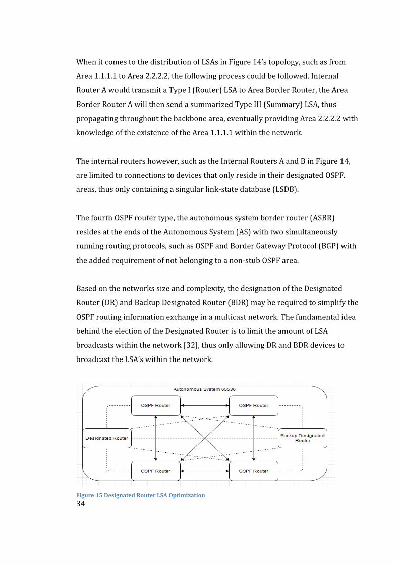
34
When it comes to the distribution of LSAs in Figure 14’s topology, such as from
Area 1.1.1.1 to Area 2.2.2.2, the following process could be followed. Internal
Router A would transmit a Type I (Router) LSA to Area Border Router, the Area
Border Router A will then send a summarized Type III (Summary) LSA, thus
propagating throughout the backbone area, eventually providing Area 2.2.2.2 with
knowledge of the existence of the Area 1.1.1.1 within the network.
The internal routers however, such as the Internal Routers A and B in Figure 14,
are limited to connections to devices that only reside in their designated OSPF.
areas, thus only containing a singular link-state database (LSDB).
The fourth OSPF router type, the autonomous system border router (ASBR)
resides at the ends of the Autonomous System (AS) with two simultaneously
running routing protocols, such as OSPF and Border Gateway Protocol (BGP) with
the added requirement of not belonging to a non-stub OSPF area.
Based on the networks size and complexity, the designation of the Designated
Router (DR) and Backup Designated Router (BDR) may be required to simplify the
OSPF routing information exchange in a multicast network. The fundamental idea
behind the election of the Designated Router is to limit the amount of LSA
broadcasts within the network [32], thus only allowing DR and BDR devices to
broadcast the LSA’s within the network.
Figure 15 Designated Router LSA Optimization
35
The reduction in required adjacencies can be seen in Figure 15, as without the
election of an DR/BDR the network would require fifteen adjacencies, which are
denoted with both dashed lines and two-sided arrows. With the deployment of a
DR, the number of required adjacencies is reduced to nine, which are denoted with
dashed lines. In the example provided in Figure 15, the DR-enabled network
achieves a significant OSPF adjacency reduction of six i.e., forty percent.
To define the distinct differences between OSPF area types, such as the backbone,
stub, NSSA and standard areas, they should adhere to the following requirements.
The common area category, which consists of the backbone and standard area
variants can divided on the basis of whether routes are propagated strictly on an
inter-area basis or not, as backbone routers will only transmit such traffic.
Consequently, standard OSPF areas will transmit traffic that is intra-area (Within
an OSPF area), inter-area (between two or more OSPF areas).
A ‘Stub OSPF area’ often resides at the edges of an Autonomous System, containing
a singular ABR device. As the stub area does not allow the transmission of external
routes from other Autonomous Systems, the amount of routing information, and
thus the number of entries in the routing database, is reduced. To accommodate
the decrease in the available routes in the LSDB and to ensure availability to
external AS routes, the ABR would form a default route which is then advertised
with a Type III LSA to the rest of the non-ABR devices inside the Stub area.
The fourth type, NSSA (Not-So-Stubby Area) is functionally quite similar to the
Stub area with a couple of exceptions. In practice, all inter-area routes are
propagated by the ABR devices. Instead of using a Type V (AS-external-LSA) LSA to
advertise the routes, all ASBRs generate Type VII (NSSA-LSA) LSAs which are then
translated back to Type V LSAs at the ABR to be propagated through to the entire
network. A distinct disadvantage to the use of a NSSA area is the fact that virtual
links, which are used to form adjacencies in non-directly connected devices, are
not allowed to pass through the NSSA area.
36
2.3.3 Integration of OSPF-TE and OSPFv3
OSPFv3 as defined in RFC 5340 by Coltun, Ferguson, Moy & Lindem [31] was
design to allow for the implementation IPv6 addressing to the original OSPFv2
standard. While the basis of the protocol remains the same, there are several
changes to the protocol itself.
The main benefit of the third version of OSPF is the inclusion of the IPv6
capabilities [31], the inclusion allowing multiple address prefixes to be included on
a from singular network interface, although the inclusion of distinct prefixes is not
supported. Additionally, the OSPFv3 routing process does not need to be
separately created as the formation of an OSPFv3 instance will automatically
generate such a process without user intervention.
OSPF-TE, or Open Shortest Path First – Traffic Engineering as defined by Katz
& Yeung in RFC 3630 [34] provides an additional method of traffic control in OSPF
networks in addition to the pre-existing ECMP (Equal-Cost Multi-Path) technology,
which divides the traffic two distinct optical links provided that the optical links
have similar configurations.
The OSPF-TE works in conjunction with the RSVP-TE to enable multiple traffic
engineering methods in IP/MPLS networks such as the Hop limit that limit the
amount LSRs the LSP can travel trough, Admin groups that determine which LSRs
should be included or excluded from the LSP process and Bandwidth, which
determines the amount of network resources that reserved for an RSVP-TE LSP.
As with several ISP topologies, many parallel optical links exist, thus presenting an
optimal scenario for the deployment of the proposed solution. As OSPF-TE reduces
the amount of duplicate LSAs caused by these parallel links. This reduction in
duplicate LSAs will simultaneously reduce the CPU processing load on the affected
routers, such as a Juniper MX960-series [35] routing platform.
37
2.4 RSVP, Resource Reservation Protocol
RSVP, Resource Reservation Protocol, as defined in RFC 2205 [36] and extended
with traffic engineering capabilities in RFC 3209 by Berger, Swallow et al. [37], is
applied to routers in order to implement QoS (Quality of Service) requests. This
reservation process reserves network resources for unidirectional traffic flows
and maintains a dynamic presence at the RSVP-enabled routers, thus enabling an
automatic adaptation to network changes. As these network changes happen
relatively often in ISP networks due to fibre cuts and maintenance windows, an
automatic restoration of the RSVP topology is a critical function of the protocol.
As a signalling protocol, RSVP can be used in conjunction with IP/MPLS networks
as a replacement for the LDP protocol, as RSVP introduces multiple new traffic
engineering applications which can used to affect the flow of traffic within the
MPLS network, with measures such as link colouring that can be achieved with the
integration of RSVP-TE (Resource Reservation Protocol – Traffic Engineering).
2.4.1 Fundamentals of RSVP
Although the formation process of a RSVP session is equivalent to the formation of
an LDP session as defined in section 2.1.3, the route determination in RSVP is
different from the LDP’s reliance on the shortest route provided by an IGP such as
OSPF. [13] The function of RSVP-TE relies on the combination of EROs (Explicit
Route Objects) and a modified SPF algorithm which is referred to as the CSPF
(Constrained Shortest Path First) algorithm.
Explicit Route Objects are used to implement limitations on the routing of MPLS
LSPs, such as forcing a specific LSP to travel through a specific route. This in
contrast with the default function of RSVP, as by default the RSVP messages will
follow a route determined by the network’s IGP e.g., OSPF or IS/IS.
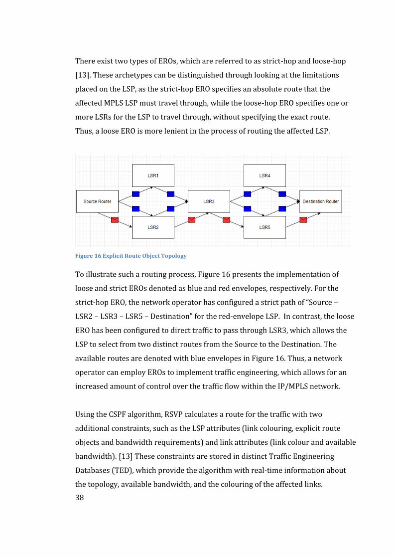
38
There exist two types of EROs, which are referred to as strict-hop and loose-hop
[13]. These archetypes can be distinguished through looking at the limitations
placed on the LSP, as the strict-hop ERO specifies an absolute route that the
affected MPLS LSP must travel through, while the loose-hop ERO specifies one or
more LSRs for the LSP to travel through, without specifying the exact route.
Thus, a loose ERO is more lenient in the process of routing the affected LSP.
Figure 16 Explicit Route Object Topology
To illustrate such a routing process, Figure 16 presents the implementation of
loose and strict EROs denoted as blue and red envelopes, respectively. For the
strict-hop ERO, the network operator has configured a strict path of “Source –
LSR2 – LSR3 – LSR5 – Destination” for the red-envelope LSP. In contrast, the loose
ERO has been configured to direct traffic to pass through LSR3, which allows the
LSP to select from two distinct routes from the Source to the Destination. The
available routes are denoted with blue envelopes in Figure 16. Thus, a network
operator can employ EROs to implement traffic engineering, which allows for an
increased amount of control over the traffic flow within the IP/MPLS network.
Using the CSPF algorithm, RSVP calculates a route for the traffic with two
additional constraints, such as the LSP attributes (link colouring, explicit route
objects and bandwidth requirements) and link attributes (link colour and available
bandwidth). [13] These constraints are stored in distinct Traffic Engineering
Databases (TED), which provide the algorithm with real-time information about
the topology, available bandwidth, and the colouring of the affected links.
39
2.4.2 Operation of RSVP
The operation of RSVP is founded on the basis of seven messages [13]:
- Path, used to transmit route messages downstream.
- PathErr, used to signal errors in the path message.
- PathTear, used to remove resource reservations on a route.
- Resv, used to request reservation of network resources.
- ResvConfirm, used to request confirmation of a reservation request.
- ResvError, used to signal errors with reservation requests.
The process of initializing an RSVP session, using the topology of Figure 16, starts
with the Source router, which sends a Path message. This Path message is sent
downstream towards the Destination router, containing information such as the
bandwidth requirements of the following traffic flow. After reaching the
Destination, outbound router then initiates a Resv message that is propagated
upstream to all the routers on the optical path to the Source router. When the Resv
message reaches the Source, a unidirectional route through the network is created,
allowing for the traffic flow to commence along the Label-Switched Path.
Should a router not receive maintenance messages for pre-determined time
however, the RSVP session would then be terminated with the propagation of an
PathTear message. The PathTear message type is used to remove the network
resource reservations along the route of the pre-existing RSVP-signalled LSP.
In the handling of errors, such as the unavailability of bandwidth along the LSP’s
route, RSVP uses ResvError and PathErr messages. To illustrate this problem in
the topology of Figure 16, should the link between LSR3 and LSR5 be congested,
the RSVP LSP carrying traffic would then be rerouted through the link trough
LSR4. In the case of no such available link existing however, the LSP setup would
conclude without the establishment of a RSVP session.
40
For the purposes of implementing network fault detection, a network
administrator could leverage the RSVP Hello process, which is propagated every
nine seconds in Junos OS-operating system devices. In a standard deployment,
RSVP is dependent on the IGP protocols for fault detection e.g., Intermediate
System to Intermediate System (IS/IS) and Open Shortest Path First (OSPF).
In operational terms, when an IGP protocol would announce that a neighbouring
device is down, RSVP will bring down the session associated with that specific
neighbour. This connectivity failure can be indicated by the lack of responses to
Keepalive messages or RSVP Hello packets. In direct contrast however, when a
neighbour would come up again, the renewal of the IGP and RSVP neighbour
adjacencies would commence, with the exception that the IGP and RSVP would
function independently from each other.
Optionally, a network operator may prefer to deploy a signalling method that can
be integrated to the RSVP implementation in the inclusion of MTU signalling as
defined under the RFC 3209 by Berger, Swallow et al. [37], which is distinct part
of the RSVP-TE (RSVP – Traffic Engineering) protocol specification.
The MTU (Maximum Transmission Unit) value which refers to the largest size
packet or frame (in bytes), which can be sent through the network as a singular
entity. As these MTU values can vary between links within an IP/MPLS network,
packet loss can be caused due to incompatible MTU values. For example, in the
case of an exceedingly large MTU value, packet loss may occur due to the MPLS
encapsulated packet being unable to be fragmented properly.
When implementing MTU signalling as part of the RSVP protocol, the ingress LER
would need to determine the lowest MTU value of the route selected by the specific
LSP and assign this value to the associated LSP. [13] Thus, any packets that would
exceed the assigned MTU value can then be fragmented into multiple packets,
before being encapsulated into MPLS and transmitted over the RSVP LSP.
41
2.4.3 Integration of RSVP-TE
RSVP, Resource Reservation Protocol - Traffic Engineering as defined in RFC 3209
by Berger, Swallow et al. [37] which is used to extend the capabilities of the RSVP
protocol such as to allow the creation of explicitly routed MPLS LSPs which are
referred to as ER-LSPs and other distinctive traffic engineering methods.
Considering the inclusions made to RSVP-TE’s PATH-message, two new attributes
were added in addition the ERO (Explicit Route Object), which is illustrated in
Figure 16. These attributes are referred to as the Label-Request Object and Session
Attribute Object, which are introduced to fulfil the new requirements for a RSVP-
TE session and for requesting a label as part of the RESV process, respectively.
As maintenance and sudden breaks of fibre connectivity are relatively common
occurrence, the inclusion of features of MPLS FRR (Fast Reroute) can be
considered to protect the RSVP-TE signalled LSP’s from the beforementioned
failure scenarios. The primary benefit of MPLS FRR on a RSVP-signalled LSP is the
significant reduction in time needed for traffic convergence after a network fault,
such as those caused by a municipal roadworks i.e., fibre cut by an excavator.
The FRR process is set up using the Ingress LER, which propagates a message to
the transit routers between the Ingress LER and the Egress LER node, that requires
these transit routers to compute backup LSP’s beforehand. Should a sudden fibre
break or a router failure occur, the traffic would then be rerouted to these backup
LSPs as a form of local repair, thus not requiring the repair of the original MPLS
LSP before traffic restoration would occur. [13] This process decreases the amount
of the time the IP/MPLS network would require healing from such a break, thus
easing the fulfilment of strict SLA contracts and uptime requirements, as is typical
in ISP-operated networks. The FRR feature can be argued to be quite similar to the
BGP Prefix Independent Convergence feature, despite functioning on a separate
aspect of network traffic restoration process.
42
3 Practical Background
This chapter covers the practical background that the thesis relies upon such as
the practical nature of an IP/MPLS-based networks operation and their
interconnection between other Autonomous Systems. The theorem and historical
significance of the security of BGP prefixes is discussed in the second section.
3.1 MPLS Core Transmission Networks
A MPLS-based core transmission network operated by an Internet Service
Provider operates as a framework for the interoperation of various technologies,
thus enabling the function of a complex and heterogenous network that offers a
high variance of services to enterprise, wholesale, and retail customers alike.
The design of a core transmission network that would employ IP/MPLS technology
is in a physical sense highly dependant on the availability of fibre pairs in long-haul
fibre cabling. The availability of vacant of fibre pairs is made a pressing issue due
to the ever-increasing amount of capacity required to fulfil the needs of the core
network. This increased demand for bandwidth can be attributed to the increase in
both mobile and fixed traffic, which commonly from the increased adoption of
high-resolution streaming services and social media platforms. Thus, as
technology’s Race to the Sea continues, so increases the bandwidth required to
facilitate the increasing demands of high-speed connectivity.
As laying new fibre optical cabling is prohibitively CAPEX intensive endeavour,
multiple methods have been developed to optimize the usage of a singular fibre
pair where available. In order to integrate multiple wavelengths of optical
connectivity into a single fibre, the concept of OTN (Optical Transport Network)
was introduced, with systems such as a DWDM (Dense Wavelength Division
Multiplexing) allowing for the integration of multiple colours (wavelengths) into a
single fibre pair, thus increasing the fibre utilization efficiency significantly.
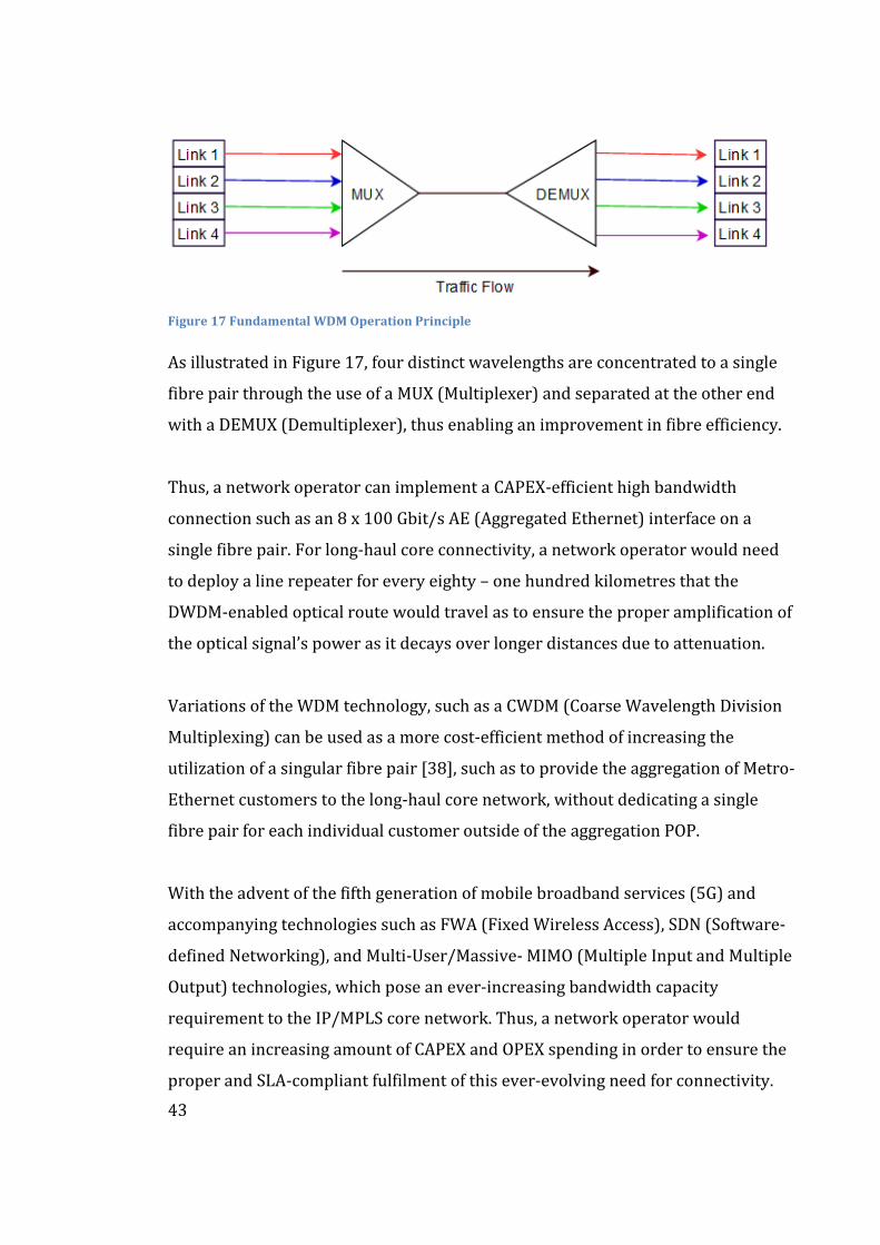
43
Figure 17 Fundamental WDM Operation Principle
As illustrated in Figure 17, four distinct wavelengths are concentrated to a single
fibre pair through the use of a MUX (Multiplexer) and separated at the other end
with a DEMUX (Demultiplexer), thus enabling an improvement in fibre efficiency.
Thus, a network operator can implement a CAPEX-efficient high bandwidth
connection such as an 8 x 100 Gbit/s AE (Aggregated Ethernet) interface on a
single fibre pair. For long-haul core connectivity, a network operator would need
to deploy a line repeater for every eighty – one hundred kilometres that the
DWDM-enabled optical route would travel as to ensure the proper amplification of
the optical signal’s power as it decays over longer distances due to attenuation.
Variations of the WDM technology, such as a CWDM (Coarse Wavelength Division
Multiplexing) can be used as a more cost-efficient method of increasing the
utilization of a singular fibre pair [38], such as to provide the aggregation of Metro-
Ethernet customers to the long-haul core network, without dedicating a single
fibre pair for each individual customer outside of the aggregation POP.
With the advent of the fifth generation of mobile broadband services (5G) and
accompanying technologies such as FWA (Fixed Wireless Access), SDN (Software-
defined Networking), and Multi-User/Massive- MIMO (Multiple Input and Multiple
Output) technologies, which pose an ever-increasing bandwidth capacity
requirement to the IP/MPLS core network. Thus, a network operator would
require an increasing amount of CAPEX and OPEX spending in order to ensure the
proper and SLA-compliant fulfilment of this ever-evolving need for connectivity.
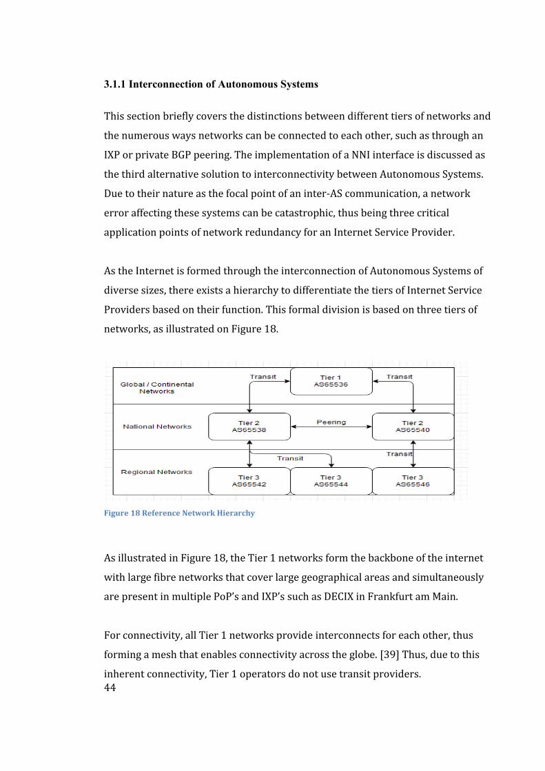
44
3.1.1 Interconnection of Autonomous Systems
This section briefly covers the distinctions between different tiers of networks and
the numerous ways networks can be connected to each other, such as through an
IXP or private BGP peering. The implementation of a NNI interface is discussed as
the third alternative solution to interconnectivity between Autonomous Systems.
Due to their nature as the focal point of an inter-AS communication, a network
error affecting these systems can be catastrophic, thus being three critical
application points of network redundancy for an Internet Service Provider.
As the Internet is formed through the interconnection of Autonomous Systems of
diverse sizes, there exists a hierarchy to differentiate the tiers of Internet Service
Providers based on their function. This formal division is based on three tiers of
networks, as illustrated on Figure 18.
Figure 18 Reference Network Hierarchy
As illustrated in Figure 18, the Tier 1 networks form the backbone of the internet
with large fibre networks that cover large geographical areas and simultaneously
are present in multiple PoP’s and IXP’s such as DECIX in Frankfurt am Main.
For connectivity, all Tier 1 networks provide interconnects for each other, thus
forming a mesh that enables connectivity across the globe. [39] Thus, due to this
inherent connectivity, Tier 1 operators do not use transit providers.
45
“Tier 2” networks are often regional operators, with a geographically limited
physical network and some hosting services, such as hosting a Netflix OCA (Open
Connect Appliance). As the networks of Tier 2 providers are often limited within
the borders of a sovereign nation such as Finland, Tier 2 operators rely on the Tier
1 operators for transit services to reach their remote customers and content
providers that operate CDNs (Content Delivery Networks) e.g., Netflix.
Tier 3 networks operate solely on the basis of providing the access to the Internet,
without providing such a solution wholesale, due to the fact that Tier 3 operators
do not operate a geographically large network, rather relying on pre-existing
networks. [39] As Tier 3 providers rely on interconnection and transit agreements
from Tier 2 networks, their operation is often limited to retail connectivity.
In order to facilitate the efficient exchange of transit traffic between Autonomous
Systems, two approaches can be undertaken. The public option to connect several
Autonomous Systems together can be achieved through the use of centralized IXP
(Internet Exchange Point) location, where the connections of multiple ISPs
converge in a single datacentre. [40]. This approach enables a CAPEX & OPEX
efficient method of enabling transit between various Autonomous Systems without
the use of a distinct transit service between these peering networks.
These IXP’s are often located in geographically central locations, such as the
Deutscher Commercial Internet Exchange in Frankfurt am Main and the
Amsterdam Internet Exchange. In addition to these major IXPs, there exists
multiple regional IXP’s such as EuroGIX in Straßburg and STHIX in Stockholm.
Private interconnections, which circumvent the previously mentioned IXP’s
through private connections between two ISPs with dedicated devices, which are
formed to allow for transit of data across these networks. These peering
relationships are often governed by peering agreements, which while often
informal handshake agreements, define the formalities of data exchange.
46
One specific use of such a private interconnection is the NNI (Network-to-Network
Interface), which allows for an increase in the reach of an ISP to the physical
network operated by the NNI partner. Practically, an NNI enables Operator A to
reach an MPLS-VPN customer that is located within Operator B’s network reach,
thus enabling a more CAPEX efficient way of reaching that specific customer.
Consequently, Operator B can reach customers within Operator A’s network.
These interconnects can be made redundant such as through the introduction of an
MC-LAG NNI, where two physically distinct devices operate using LACP signalling,
thus enabling a hardware redundancy for the interconnect. Additionally, a Layer 1
approach such as with multiple fibre connections between the interconnecting
devices can provide optical fault resiliency for the NNI connection. [41] In this
approach to redundancy, one of the routers would function as the active interface
for the NNI, while the standby router would wait for a network error to occur
before activation. Should such a network error occur, a fast failover process would
occur, thus triggering the transition of the standby router to the active role.
A peculiar aspect of CDNs (Content Delivery Networks) is that massive quantities
of data must be transmitted across multiple networks in order to reach their end-
users, thus facilitating the usage of multiple network interconnects. [42] As this
transit of data can prove costly for an ISP to manage, the implementation of local
caches such as the Netflix OCA (Open Connect Appliance) at key IXP’s and Tier 2
ISP PoPs can be used to reduce the amount of traffic that would need to be
requisitioned from other networks, thus increasing transit costs.
As the implementation of a network content cache would reroute the traffic from
transit providers and their interconnects to the networks of the ISP, thus
effectively reducing the amount of transit traffic. [42] Thus, by hosting a Netflix
OCA for example can be construed as to decrease the amount of OPEX spending
required to efficiently serve Netflix content to customers, as the need for transit
traffic would be reduced quite dramatically.
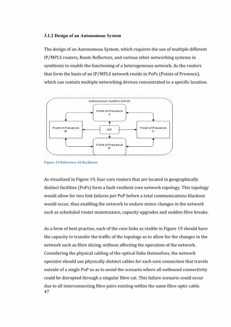
47
3.1.2 Design of an Autonomous System
The design of an Autonomous System, which requires the use of multiple different
IP/MPLS routers, Route Reflectors, and various other networking systems in
symbiosis to enable the functioning of a heterogeneous network. As the routers
that form the basis of an IP/MPLS network reside in PoPs (Points of Presence),
which can contain multiple networking devices concentrated to a specific location.
Figure 19 Reference AS Backbone
As visualized in Figure 19, four core routers that are located in geographically
distinct facilities (PoPs) form a fault-resilient core network topology. This topology
would allow for two link failures per PoP before a total communications blackout
would occur, thus enabling the network to endure minor changes in the network
such as scheduled router maintenance, capacity upgrades and sudden fibre breaks.
As a form of best practise, each of the core links as visible in Figure 19 should have
the capacity to transfer the traffic of the topology as to allow for the changes in the
network such as fibre slicing, without affecting the operation of the network.
Considering the physical cabling of the optical links themselves, the network
operator should use physically distinct cables for each core connection that travels
outside of a single PoP so as to avoid the scenario where all outbound connectivity
could be disrupted through a singular fibre cut. This failure scenario could occur
due to all interconnecting fibre pairs existing within the same fibre optic cable.
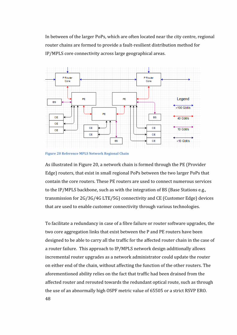
48
In between of the larger PoPs, which are often located near the city centre, regional
router chains are formed to provide a fault-resilient distribution method for
IP/MPLS core connectivity across large geographical areas.
Figure 20 Reference MPLS Network Regional Chain
As illustrated in Figure 20, a network chain is formed through the PE (Provider
Edge) routers, that exist in small regional PoPs between the two larger PoPs that
contain the core routers. These PE routers are used to connect numerous services
to the IP/MPLS backbone, such as with the integration of BS (Base Stations e.g.,
transmission for 2G/3G/4G LTE/5G) connectivity and CE (Customer Edge) devices
that are used to enable customer connectivity through various technologies.
To facilitate a redundancy in case of a fibre failure or router software upgrades, the
two core aggregation links that exist between the P and PE routers have been
designed to be able to carry all the traffic for the affected router chain in the case of
a router failure. This approach to IP/MPLS network design additionally allows
incremental router upgrades as a network administrator could update the router
on either end of the chain, without affecting the function of the other routers. The
aforementioned ability relies on the fact that traffic had been drained from the
affected router and rerouted towards the redundant optical route, such as through
the use of an abnormally high OSPF metric value of 65505 or a strict RSVP ERO.
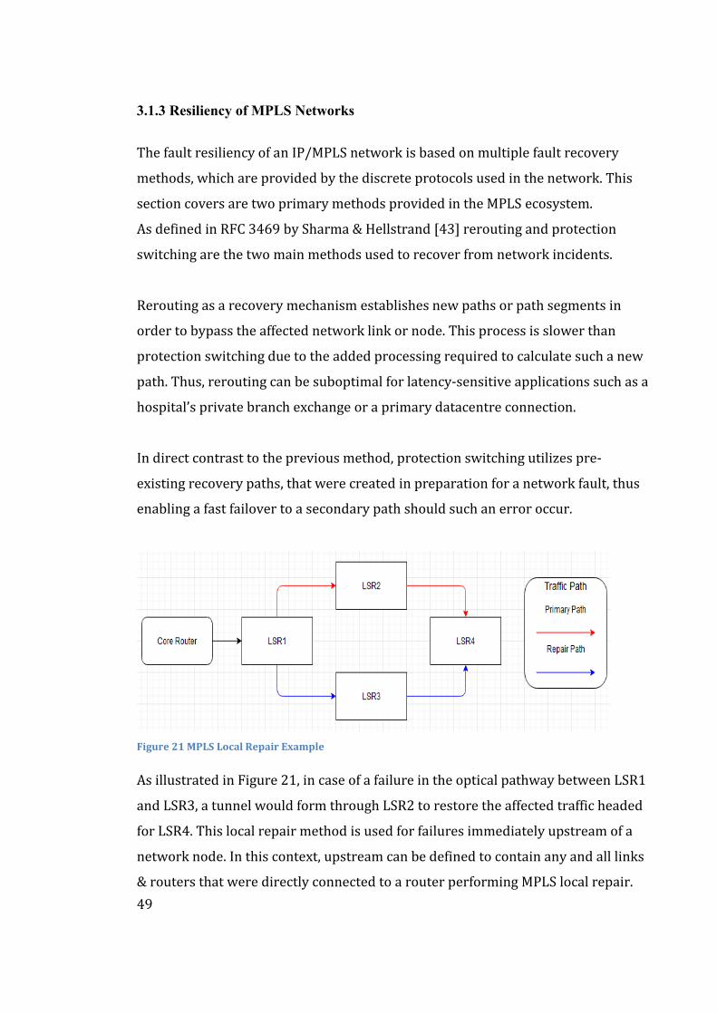
49
3.1.3 Resiliency of MPLS Networks
The fault resiliency of an IP/MPLS network is based on multiple fault recovery
methods, which are provided by the discrete protocols used in the network. This
section covers are two primary methods provided in the MPLS ecosystem.
As defined in RFC 3469 by Sharma & Hellstrand [43] rerouting and protection
switching are the two main methods used to recover from network incidents.
Rerouting as a recovery mechanism establishes new paths or path segments in
order to bypass the affected network link or node. This process is slower than
protection switching due to the added processing required to calculate such a new
path. Thus, rerouting can be suboptimal for latency-sensitive applications such as a
hospital’s private branch exchange or a primary datacentre connection.
In direct contrast to the previous method, protection switching utilizes pre-
existing recovery paths, that were created in preparation for a network fault, thus
enabling a fast failover to a secondary path should such an error occur.
Figure 21 MPLS Local Repair Example
As illustrated in Figure 21, in case of a failure in the optical pathway between LSR1
and LSR3, a tunnel would form through LSR2 to restore the affected traffic headed
for LSR4. This local repair method is used for failures immediately upstream of a
network node. In this context, upstream can be defined to contain any and all links
& routers that were directly connected to a router performing MPLS local repair.
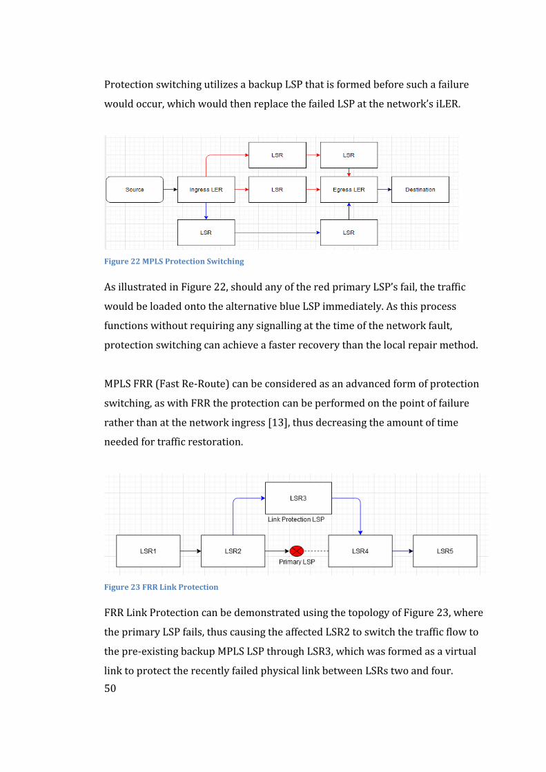
50
Protection switching utilizes a backup LSP that is formed before such a failure
would occur, which would then replace the failed LSP at the network’s iLER.
Figure 22 MPLS Protection Switching
As illustrated in Figure 22, should any of the red primary LSP’s fail, the traffic
would be loaded onto the alternative blue LSP immediately. As this process
functions without requiring any signalling at the time of the network fault,
protection switching can achieve a faster recovery than the local repair method.
MPLS FRR (Fast Re-Route) can be considered as an advanced form of protection
switching, as with FRR the protection can be performed on the point of failure
rather than at the network ingress [13], thus decreasing the amount of time
needed for traffic restoration.
Figure 23 FRR Link Protection
FRR Link Protection can be demonstrated using the topology of Figure 23, where
the primary LSP fails, thus causing the affected LSR2 to switch the traffic flow to
the pre-existing backup MPLS LSP through LSR3, which was formed as a virtual
link to protect the recently failed physical link between LSRs two and four.
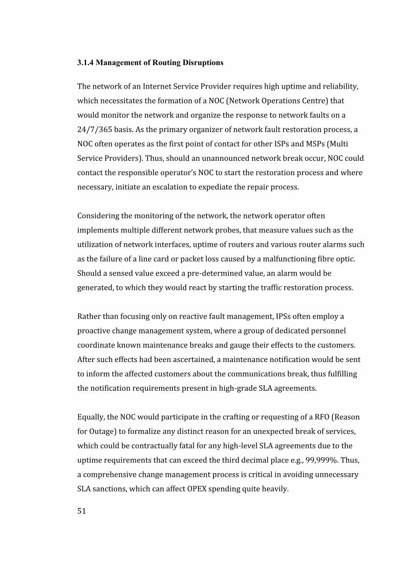
51
3.1.4 Management of Routing Disruptions
The network of an Internet Service Provider requires high uptime and reliability,
which necessitates the formation of a NOC (Network Operations Centre) that
would monitor the network and organize the response to network faults on a
24/7/365 basis. As the primary organizer of network fault restoration process, a
NOC often operates as the first point of contact for other ISPs and MSPs (Multi
Service Providers). Thus, should an unannounced network break occur, NOC could
contact the responsible operator’s NOC to start the restoration process and where
necessary, initiate an escalation to expediate the repair process.
Considering the monitoring of the network, the network operator often
implements multiple different network probes, that measure values such as the
utilization of network interfaces, uptime of routers and various router alarms such
as the failure of a line card or packet loss caused by a malfunctioning fibre optic.
Should a sensed value exceed a pre-determined value, an alarm would be
generated, to which they would react by starting the traffic restoration process.
Rather than focusing only on reactive fault management, IPSs often employ a
proactive change management system, where a group of dedicated personnel
coordinate known maintenance breaks and gauge their effects to the customers.
After such effects had been ascertained, a maintenance notification would be sent
to inform the affected customers about the communications break, thus fulfilling
the notification requirements present in high-grade SLA agreements.
Equally, the NOC would participate in the crafting or requesting of a RFO (Reason
for Outage) to formalize any distinct reason for an unexpected break of services,
which could be contractually fatal for any high-level SLA agreements due to the
uptime requirements that can exceed the third decimal place e.g., 99,999%. Thus,
a comprehensive change management process is critical in avoiding unnecessary
SLA sanctions, which can affect OPEX spending quite heavily.
52
3.2 Security of BGP Prefixes
This section covers the practical theorem of BGP prefixes and their relevance in the
routing between Autonomous Systems. Additionally, the malicious behaviour
referred to as BGP Prefix “Hijacking” is presented with a case study about the BGP
incident from February 2008 concerning Pakistan Telecom (AS17557), so as to
form a basis for the decisions made in the fifth chapter.
3.2.1 BGP Prefixes & Hijacking
Due to inherent lack of security mechanisms such as peer authentication or
validity verification of a received prefix in the propagation of the Border Gateway
Protocol, BGP is vulnerable various threats which can, according to Hakimi,
Saputra & Nugraha [44] have a critical effect that can severely inhibit the operation
of the entire Internet, the network to end all networks.
This lack of security mechanisms can be attributed to the initial trust-based
operation of BGP with traditional peering being agreed upon by trusted individuals
within different Autonomous Systems thus not necessarily requiring any
authentication to take place, as the two parties trusted each other.
In normal operations an Autonomous System should only advertise BGP prefixes
that it either owns directly or has a legitimate path towards. A malicious, whether
advertently or inadvertently such as due to a configuration error [44], network
operator could advertise a prefix that does not belong to it. This can be achieved
through methods such as forging of an AS-PATH to favour their designated route
or propagating more specific prefixes than the owner of the affected prefix.
After the propagation of a malicious prefix advertisement has completed and been
accepted by other Autonomous Systems, the affected prefix would then be
“hijacked” by the malicious network operator, thus allowing the operator to either
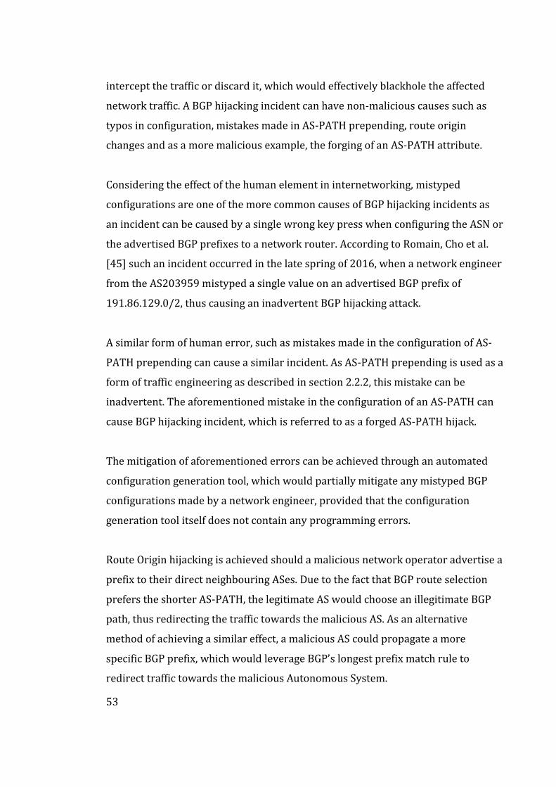
53
intercept the traffic or discard it, which would effectively blackhole the affected
network traffic. A BGP hijacking incident can have non-malicious causes such as
typos in configuration, mistakes made in AS-PATH prepending, route origin
changes and as a more malicious example, the forging of an AS-PATH attribute.
Considering the effect of the human element in internetworking, mistyped
configurations are one of the more common causes of BGP hijacking incidents as
an incident can be caused by a single wrong key press when configuring the ASN or
the advertised BGP prefixes to a network router. According to Romain, Cho et al.
[45] such an incident occurred in the late spring of 2016, when a network engineer
from the AS203959 mistyped a single value on an advertised BGP prefix of
191.86.129.0/2, thus causing an inadvertent BGP hijacking attack.
A similar form of human error, such as mistakes made in the configuration of AS-
PATH prepending can cause a similar incident. As AS-PATH prepending is used as a
form of traffic engineering as described in section 2.2.2, this mistake can be
inadvertent. The aforementioned mistake in the configuration of an AS-PATH can
cause BGP hijacking incident, which is referred to as a forged AS-PATH hijack.
The mitigation of aforementioned errors can be achieved through an automated
configuration generation tool, which would partially mitigate any mistyped BGP
configurations made by a network engineer, provided that the configuration
generation tool itself does not contain any programming errors.
Route Origin hijacking is achieved should a malicious network operator advertise a
prefix to their direct neighbouring ASes. Due to the fact that BGP route selection
prefers the shorter AS-PATH, the legitimate AS would choose an illegitimate BGP
path, thus redirecting the traffic towards the malicious AS. As an alternative
method of achieving a similar effect, a malicious AS could propagate a more
specific BGP prefix, which would leverage BGP’s longest prefix match rule to
redirect traffic towards the malicious Autonomous System.
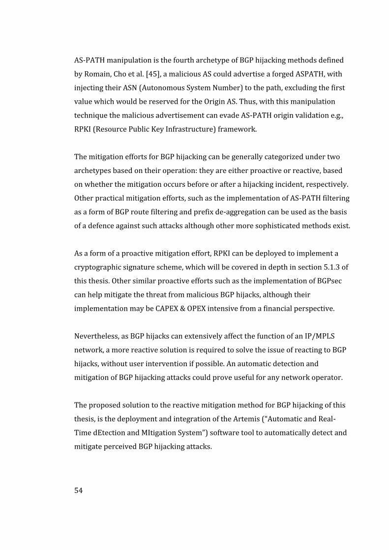
54
AS-PATH manipulation is the fourth archetype of BGP hijacking methods defined
by Romain, Cho et al. [45], a malicious AS could advertise a forged ASPATH, with
injecting their ASN (Autonomous System Number) to the path, excluding the first
value which would be reserved for the Origin AS. Thus, with this manipulation
technique the malicious advertisement can evade AS-PATH origin validation e.g.,
RPKI (Resource Public Key Infrastructure) framework.
The mitigation efforts for BGP hijacking can be generally categorized under two
archetypes based on their operation: they are either proactive or reactive, based
on whether the mitigation occurs before or after a hijacking incident, respectively.
Other practical mitigation efforts, such as the implementation of AS-PATH filtering
as a form of BGP route filtering and prefix de-aggregation can be used as the basis
of a defence against such attacks although other more sophisticated methods exist.
As a form of a proactive mitigation effort, RPKI can be deployed to implement a
cryptographic signature scheme, which will be covered in depth in section 5.1.3 of
this thesis. Other similar proactive efforts such as the implementation of BGPsec
can help mitigate the threat from malicious BGP hijacks, although their
implementation may be CAPEX & OPEX intensive from a financial perspective.
Nevertheless, as BGP hijacks can extensively affect the function of an IP/MPLS
network, a more reactive solution is required to solve the issue of reacting to BGP
hijacks, without user intervention if possible. An automatic detection and
mitigation of BGP hijacking attacks could prove useful for any network operator.
The proposed solution to the reactive mitigation method for BGP hijacking of this
thesis, is the deployment and integration of the Artemis (“Automatic and Real-
Time dEtection and MItigation System”) software tool to automatically detect and
mitigate perceived BGP hijacking attacks.
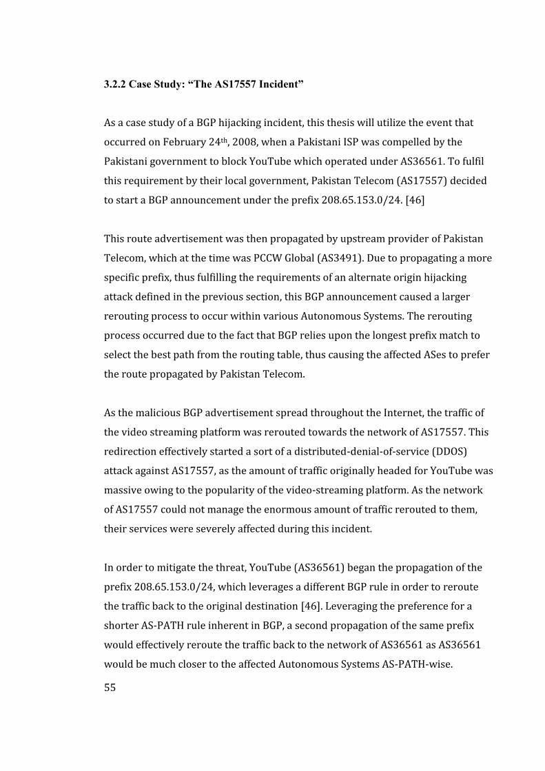
55
3.2.2 Case Study: “The AS17557 Incident”
As a case study of a BGP hijacking incident, this thesis will utilize the event that
occurred on February 24th, 2008, when a Pakistani ISP was compelled by the
Pakistani government to block YouTube which operated under AS36561. To fulfil
this requirement by their local government, Pakistan Telecom (AS17557) decided
to start a BGP announcement under the prefix 208.65.153.0/24. [46]
This route advertisement was then propagated by upstream provider of Pakistan
Telecom, which at the time was PCCW Global (AS3491). Due to propagating a more
specific prefix, thus fulfilling the requirements of an alternate origin hijacking
attack defined in the previous section, this BGP announcement caused a larger
rerouting process to occur within various Autonomous Systems. The rerouting
process occurred due to the fact that BGP relies upon the longest prefix match to
select the best path from the routing table, thus causing the affected ASes to prefer
the route propagated by Pakistan Telecom.
As the malicious BGP advertisement spread throughout the Internet, the traffic of
the video streaming platform was rerouted towards the network of AS17557. This
redirection effectively started a sort of a distributed-denial-of-service (DDOS)
attack against AS17557, as the amount of traffic originally headed for YouTube was
massive owing to the popularity of the video-streaming platform. As the network
of AS17557 could not manage the enormous amount of traffic rerouted to them,
their services were severely affected during this incident.
In order to mitigate the threat, YouTube (AS36561) began the propagation of the
prefix 208.65.153.0/24, which leverages a different BGP rule in order to reroute
the traffic back to the original destination [46]. Leveraging the preference for a
shorter AS-PATH rule inherent in BGP, a second propagation of the same prefix
would effectively reroute the traffic back to the network of AS36561 as AS36561
would be much closer to the affected Autonomous Systems AS-PATH-wise.
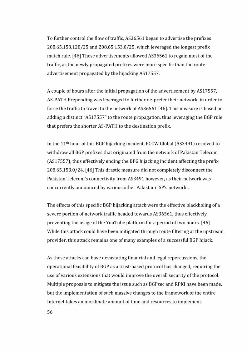
56
To further control the flow of traffic, AS36561 began to advertise the prefixes
208.65.153.128/25 and 208.65.153.0/25, which leveraged the longest prefix
match rule. [46] These advertisements allowed AS36561 to regain most of the
traffic, as the newly propagated prefixes were more specific than the route
advertisement propagated by the hijacking AS17557.
A couple of hours after the initial propagation of the advertisement by AS17557,
AS-PATH Prepending was leveraged to further de-prefer their network, in order to
force the traffic to travel to the network of AS36561 [46]. This measure is based on
adding a distinct “AS17557” to the route propagation, thus leveraging the BGP rule
that prefers the shorter AS-PATH to the destination prefix.
In the 11th hour of this BGP hijacking incident, PCCW Global (AS3491) resolved to
withdraw all BGP prefixes that originated from the network of Pakistan Telecom
(AS17557), thus effectively ending the BPG hijacking incident affecting the prefix
208.65.153.0/24. [46] This drastic measure did not completely disconnect the
Pakistan Telecom’s connectivity from AS3491 however, as their network was
concurrently announced by various other Pakistani ISP’s networks.
The effects of this specific BGP hijacking attack were the effective blackholing of a
severe portion of network traffic headed towards AS36561, thus effectively
preventing the usage of the YouTube platform for a period of two hours. [46]
While this attack could have been mitigated through route filtering at the upstream
provider, this attack remains one of many examples of a successful BGP hijack.
As these attacks can have devastating financial and legal repercussions, the
operational feasibility of BGP as a trust-based protocol has changed, requiring the
use of various extensions that would improve the overall security of the protocol.
Multiple proposals to mitigate the issue such as BGPsec and RPKI have been made,
but the implementation of such massive changes to the framework of the entire
Internet takes an inordinate amount of time and resources to implement.
57
4 BGP Prefix Independent Convergence
This chapter covers the current situation with BGP convergence and the proposed
solution of the thesis, which utilizes a new BGP convergence feature offered by
networking hardware vendors, such as Cisco Systems and Juniper Networks.
4.1 BGP Convergence
In traditional BGP convergence, the process of route convergence begins with the
detection of network fault e.g., the failure of an optical link due to a sudden fibre
break. In order for the process of convergence to begin, the affected routers must
receive information about such a failure. This deliverance of information about the
fault can be transmitted to the BGP process in multiple ways, such as through the
use of either IGP or BFD protocols. [48]. Additionally, the usage of the interface
events e.g., interface down can be used for this process.
After learning of such an error, BGP initiates the removal of the affected routes
from the RIB (Routing Information Base). The RIB would then proceed to
withdraw routes from the FIB (Forwarding Information Base). After the FIB has
cleared the affected routes, the process continues by allowing the propagation of
withdrawal messages to the connected neighbour’s, which is dependent on the
previously configured MRAI (Minimum Router Advertisement Interval) timer.
[49] These withdrawal messages would cause the receiving routers to remove the
affected routes from their respective routing and forwarding tables.
The neighbouring routers would then initiate the propagation of their newly
formed best paths, thus allowing the initial router to start the recalculation
process. After this process, the router would then calculate the upcoming path for
the affected prefixes, installing these routes to the Routing Information Base. After
completion, the RIB will then install these routes to the Forwarding Information
Base thus completing the BGP convergence process. [48]
58
4.1.2 Proposed Mitigations
Multiple methods do exist to mitigate the effects of changes affecting the BGP
network, thus easing the process of convergence after a network change, such as
with the modification of the MRAI timer and implementation of a route
suppression scheme which is often referred to as route damping.
The MRAI timer which affects the rate of which the router can send route
advertisements through the introduction of a limiter value, that prevents a second
advertisement’s propagation before the MRAI timer has expired. Thus, the
intentional modification of the MRAI timer can be used to reduce the amount of
time needed for the propagation of new routes, while not simultaneously
compromising the overall function of the network.
As this MRAI value is configured to be 30 seconds by default in accordance with
RFC 4271 [18], according to Griffin & Premore [50] there exists an Autonomous
System-specific optimal MRAI value that would reduce the amount of time before
route convergence without simultaneously prohibitively increasing the associated
processing load for all MRAI-modified routers.
Route damping can be defined as the process of suppressing BGP route
advertisements which are caused by a flapping route. [51] These flapping, or in
layman’s terms unstable routes, can cause unnecessary traffic loss as the process
of flapping causes traffic blackholing, as the traffic would be discarded due the
router having not yet recalculated the necessary routes for the prefixes therein.
The process of suppressing the propagation of these routes is based on a “trust
value”, which when exceeded due to previous instability will cause the
advertisements of the affected route to be effectively ignored and thus removed
from the routing process for a pre-determined amount of time, such as 30 or 60
minutes as defined in RFC 2439 [51] authored by Villamizar, Chandra & Govindan.
59
4.1.3 Prefix Independent Convergence
The process of reducing the time required for BGP convergence independently
from the amount of the prefixes is proposed by Bashandy, Filsfils and Mohapatra
[52] in the IETF draft document on the implementation of an advanced BGP
feature, which is referred to as BGP Prefix Independent Convergence.
The fundamental improvement that BGP Prefix Independent Convergence
introduces to the traditional BGP convergence is the introduction of one or more
pre-installed and pre-computed BGP next-hops that are installed to the associated
BGP pathlist. [52] This precomputation mechanism is made available by the
introduction of the Add-Path, BGP Best-External and diverse path mechanisms.
The foundation of the proposal relies on two distinct pillars, which are the
introduction of a hierarchical FIB architecture and forwarding chains. The first of
these pillars is the introduction of a hierarchy to the Forwarding Information
Database, which exists on the dataplane. This proposed hierarchy is defined as
follows according to Bashandy, Filsfils and Mohapatra [52]:
- Lookup of a BGP Leaf, which contains the local label or prefix.
- Referring to the BGP Pathlist, which contains an array of routes for a
specific destination.
- Resolving the IGP Pathlist, which can be provided by an IGP e.g., OSPF.
- Consultancy of an Adjacency of directly connected next hops.
The second pillar introduces a concept on the construction of a forwarding chain,
for which the following process is defined [52]. After the introduction of an BGP
prefix by the RIB to the FIB, the prefix is assigned as a dependency to a Pathlist,
which contains a list of outgoing paths out of the router that operates the FIB.
Should such an applicable pre-existing Pathlist not exist, the Forwarding
Information Base would then proceed to create one.
60
The resolution of the forwarding chain would then commence with resolving the
paths contained within the Pathlist, with the next hop being resolved by the
Internal Gateway Protocol through the process of finding the matching IGP prefix.
[52] As a result, a hierarchical forwarding chain is formed where pathlists form
clusters of prefixes which are then used form the basis of the implementations of
the technology which are referred to as BGP PIC Core and BGP PIC Edge.
BGP PIC Core is the first application of the PIC feature, which is utilized in the
scenario where an IP/MPLS node or a link suffers an operational failure, whereas
the BGP next-hop remains reachable. The aforementioned scenario could be
caused by two types of link failures, which are differentiated by the location of the
failure i.e., whether the failure occurs on an attached or remote link. Subsequently,
the failure of a network node would be regarded as a link failure. On the other
hand, the second feature which is referred to as BGP PIC Edge, would be applicable
in the scenario where the failure affects an edge node or link, such as a PE – CE link
failure, which would affect connectivity of the CE (Customer Equipment).
Should a remote link fail, the IGP on the network ingress PE (Provider Edge) router
would receive a topology update, which then would cause the reconvergence of the
IGP. This reconvergence is then used to either remove or modify the pre-existing
path from the IGP prefix for the associated BGP next-hops. [52] Thereafter, the IGP
would then follow-up with reprocessing of the newly modified IGP leaves with the
modified BGP leaves.
Should a local failure affect the router, it would be detected near-instantly by the
affected FIB, which would then mark the associated paths as unusable, thus only
requiring the modification of the associated IGP pathlists rather than all pathlists
located on the device. Consequently, the traffic restoration would occur in
synchronization with the IGP convergence which can be achieved within a time
period of fifty milliseconds according to Bashandy, Filsfils and Mohapatra. [52]
61
In such a scenario, the FIB would proceed to delete the IGP leaf associated with the
affected edge node. Subsequently, the FIB would mark all BGP pathlists dependent
on the affected IGP leaf as unresolved, thus initiation a new convergence process.
Considering the scenario where a primary BGP path would become unresolved, the
forwarding engine would then proceed to send the affected traffic towards the
secondary optical path. Therefore, a fast failover would be achievable, thus
allowing the traffic restoration to occur within the fifty milliseconds as previously
mentioned.
When assessing the implementability of the BGP Prefix Independent Convergence
feature, a network administrator would need to consider various aspects of the
technology, such as automation, deployment, and overall performance.
The functional automation of BGP PIC would not require any human intervention
after the deployment, which is due fact that the solution is based on the
automation of the FIB. This automation is achieved through the utilization of the
process hierarchy between the BGP and IGP pathlists.
Deployment-wise, BGP PIC allows for an incremental deployment process, as the
BGP PIC solution does not require the other routers to utilize the feature to achieve
the full functionality for the BGP PIC-enabled router. Thus, an incremental
deployment of BGP would be possible in standard scheduled maintenance
windows chosen by the aforementioned Internet Service Provider.
As for Performance, as the BGP PIC solution would utilize pre-computed backup
path, which can be achieved without regard to the amount of BGP Prefixes affected,
a reduction in both the required number of CPU cycles and convergence times, it
could be said that BGP PIC increases the overall performance of the network as the
resiliency and convergence efficiency of the network would be significantly
increased through the adoption of BGP Prefix Independent Convergence.
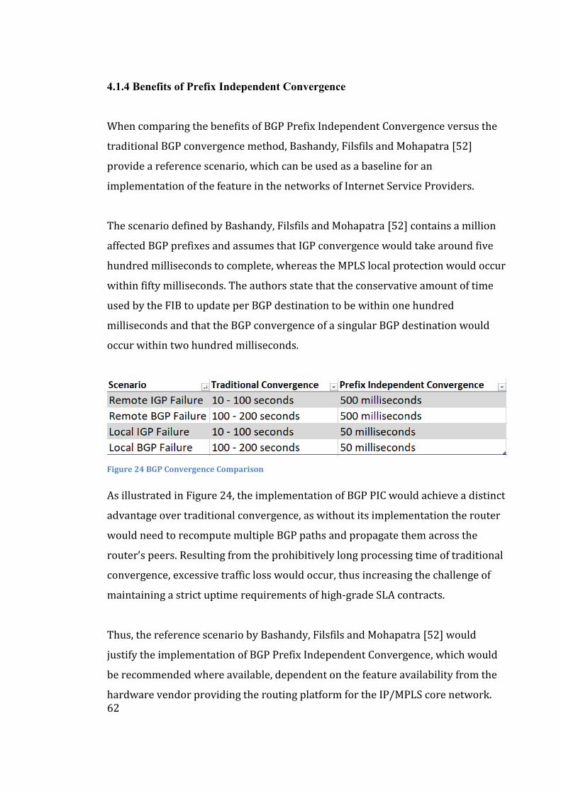
62
4.1.4 Benefits of Prefix Independent Convergence
When comparing the benefits of BGP Prefix Independent Convergence versus the
traditional BGP convergence method, Bashandy, Filsfils and Mohapatra [52]
provide a reference scenario, which can be used as a baseline for an
implementation of the feature in the networks of Internet Service Providers.
The scenario defined by Bashandy, Filsfils and Mohapatra [52] contains a million
affected BGP prefixes and assumes that IGP convergence would take around five
hundred milliseconds to complete, whereas the MPLS local protection would occur
within fifty milliseconds. The authors state that the conservative amount of time
used by the FIB to update per BGP destination to be within one hundred
milliseconds and that the BGP convergence of a singular BGP destination would
occur within two hundred milliseconds.
Figure 24 BGP Convergence Comparison
As illustrated in Figure 24, the implementation of BGP PIC would achieve a distinct
advantage over traditional convergence, as without its implementation the router
would need to recompute multiple BGP paths and propagate them across the
router’s peers. Resulting from the prohibitively long processing time of traditional
convergence, excessive traffic loss would occur, thus increasing the challenge of
maintaining a strict uptime requirements of high-grade SLA contracts.
Thus, the reference scenario by Bashandy, Filsfils and Mohapatra [52] would
justify the implementation of BGP Prefix Independent Convergence, which would
be recommended where available, dependent on the feature availability from the
hardware vendor providing the routing platform for the IP/MPLS core network.
63
4.2 Deployment of Prefix Independent Convergence
The following chapter covers the implementation of BGP Prefix Independent
Convergence from three available IP/MPLS router ecosystem vendors: Cisco
Systems, Juniper Networks and Huawei Technologies. In addition to these three
vendors, other hardware vendors such as Arista and Nokia offer this functionality
in their respective IP/MPLS routing platforms.
4.2.1 Cisco Systems
The implementation of BGP Prefix Independent Convergence on routers
manufactured by Cisco Systems is referred to as “BGP PIC Edge for IP and MPLS-
VPN “. The Cisco Systems implementation of BGP Prefix Independent Convergence
is enforceable on both core and edge node failures. [48]
The BGP PIC feature uses the creation of a secondary route, which is then stored in
the RIB (Routing Information Base), Cisco-proprietary CEF (Cisco Express
Forwarding) and the FIB (Forwarding Information Base). [48] Thus, should the
IGP protocol e.g., OSPF or IS/IS detect a network node failure, the traffic could be
rerouted to the associated backup path instantly, thus enabling a nearly hitless
failover process for the affected traffic.
Due the dependence on the IGP’s ability to detect a node failure within the
network, Cisco requires the usage of BFD (Bidirectional Forwarding Detection) to
enable the rapid detection of link failures in the network in addition to the
detection ability of the chosen Internal Gateway Protocol.
The function of the Cisco implementation of BGP PIC depends on four categories of
added functionalities on top of the pre-existing BGP, RIB, CEF and MPLS features.
Considering the effect on the operation of BGP itself, the PIC feature calculates a
secondary path for each individual prefix such as those belonging to the IPv4
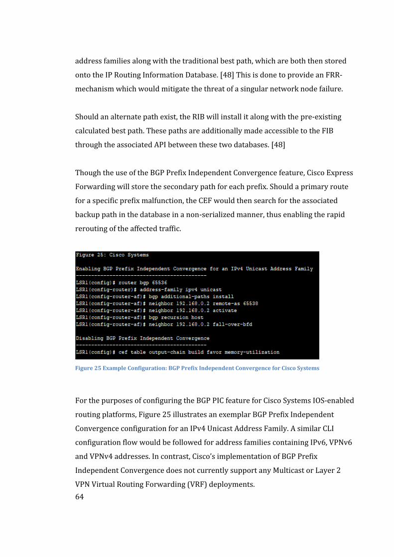
64
address families along with the traditional best path, which are both then stored
onto the IP Routing Information Database. [48] This is done to provide an FRR-
mechanism which would mitigate the threat of a singular network node failure.
Should an alternate path exist, the RIB will install it along with the pre-existing
calculated best path. These paths are additionally made accessible to the FIB
through the associated API between these two databases. [48]
Though the use of the BGP Prefix Independent Convergence feature, Cisco Express
Forwarding will store the secondary path for each prefix. Should a primary route
for a specific prefix malfunction, the CEF would then search for the associated
backup path in the database in a non-serialized manner, thus enabling the rapid
rerouting of the affected traffic.
Figure 25 Example Configuration: BGP Prefix Independent Convergence for Cisco Systems
For the purposes of configuring the BGP PIC feature for Cisco Systems IOS-enabled
routing platforms, Figure 25 illustrates an exemplar BGP Prefix Independent
Convergence configuration for an IPv4 Unicast Address Family. A similar CLI
configuration flow would be followed for address families containing IPv6, VPNv6
and VPNv4 addresses. In contrast, Cisco’s implementation of BGP Prefix
Independent Convergence does not currently support any Multicast or Layer 2
VPN Virtual Routing Forwarding (VRF) deployments.
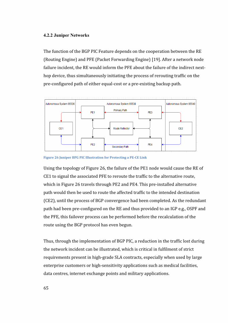
65
4.2.2 Juniper Networks
The function of the BGP PIC Feature depends on the cooperation between the RE
(Routing Engine) and PFE (Packet Forwarding Engine) [19]. After a network node
failure incident, the RE would inform the PFE about the failure of the indirect next-
hop device, thus simultaneously initiating the process of rerouting traffic on the
pre-configured path of either equal-cost or a pre-existing backup path.
Figure 26 Juniper BPG PIC Illustration for Protecting a PE-CE Link
Using the topology of Figure 26, the failure of the PE1 node would cause the RE of
CE1 to signal the associated PFE to reroute the traffic to the alternative route,
which in Figure 26 travels through PE2 and PE4. This pre-installed alternative
path would then be used to route the affected traffic to the intended destination
(CE2), until the process of BGP convergence had been completed. As the redundant
path had been pre-configured on the RE and thus provided to an IGP e.g., OSPF and
the PFE, this failover process can be performed before the recalculation of the
route using the BGP protocol has even begun.
Thus, through the implementation of BGP PIC, a reduction in the traffic lost during
the network incident can be illustrated, which is critical in fulfilment of strict
requirements present in high-grade SLA contracts, especially when used by large
enterprise customers or high-sensitivity applications such as medical facilities,
data centres, internet exchange points and military applications.
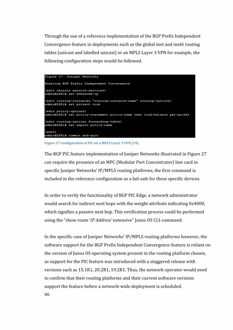
66
Through the use of a reference implementation of the BGP Prefix Independent
Convergence-feature in deployments such as the global inet and inet6 routing
tables (unicast and labelled unicast) or an MPLS Layer 3 VPN for example, the
following configuration steps would be followed.
Figure 27 Configuration of PIC on a MPLS Layer 3 VPN [19]
The BGP PIC feature implementation of Juniper Networks illustrated in Figure 27
can require the presence of an MPC (Modular Port Concentrator) line card in
specific Juniper Networks’ IP/MPLS routing platforms, the first command is
included in the reference configuration as a fail-safe for these specific devices.
In order to verify the functionality of BGP PIC Edge, a network administrator
would search for indirect next hops with the weight attribute indicating 0x4000,
which signifies a passive next hop. This verification process could be performed
using the “show route ‘IP Address’ extensive” Junos OS CLI-command.
In the specific case of Juniper Networks’ IP/MPLS routing platforms however, the
software support for the BGP Prefix Independent Convergence-feature is reliant on
the version of Junos OS operating system present in the routing platform chosen,
as support for the PIC feature was introduced with a staggered release with
versions such as 15.1R1, 20.2R1, 19.2R1. Thus, the network operator would need
to confirm that their routing platforms and their current software versions
support the feature before a network-wide deployment is scheduled.
67
4.2.3 Huawei Technologies
The implementation of BGP Prefix Independent Convergence by Huawei
Technologies supports the functionality on various applications, such as iBGP and
single-hop routes. Functionally, Huawei’s implementation functions on a similar
basis to the previous implementations, but with the notable exception of the
configuration language made to enable the aforementioned feature.
In Huawei CLI, Prefix Independent Convergence is referred to as BGP Fast-Refresh,
with a notable exception in comparison to other vendors, as on Huawei S9700-
device for example, the feature is enabled by default. Conversely, when either BGP
Load Balancing (ECMP) or ‘BGP Auto FRR’ features are enabled, the BGP PIC
feature will not function. [53] From the perspective of a command line (CLI)
configuration the BGP PIC feature in Huawei’s routers is configured as follows:
- <LSR1> “system-view”
Enables configuration level of the router, similarly to the configure
command in routing platforms by Cisco Systems.
- <LSR1> “bgp fast-refresh enable “
This command enables the BGP PIC feature for iBGP routes.
- <LSR1> “single-nexthop bgp fast-refresh enable”
This command enables the BGP PIC feature for single-hop routes.
- <LSR1> “undo bgp fast-refresh enable “
This command disables the BGP PIC feature.
The process of disabling the BGP PIC feature in the devices manufactured by
Huawei Technologies requires the resetting of all LPUs (Line Processing Units).
This process would cause a network flap on the affected line cards should such a
choice be made to disable the feature. As this flap could cause harsh disruptions to
production traffic in an ISP’s IP/MPLS network, it is advised that this configuration
is to be made within a maintenance window with the proper precautions.
68
5 BGP Prefix Security
This chapter covers the prefix security of the Border Gateway Protocol. For the
mitigation of the threats concerning the BGP prefix, this thesis proposes the
symbiotic implementation of two prefix security measures. As a proactive
measure, the implementation of RPKI (Resource Public Key Infrastructure) to
introduce route origin validation, whereas the Artemis BGP monitoring tool is
proposed to increase the reactive security of the BGP prefixes. The introduction of
BGPsec forms a forward-looking perspective into IP/MPLS network design.
5.1 Proactive Mitigation: RPKI
Resource Public Key Infrastructure or RPKI is the proposed solution to the
proactive security of BGP prefixes, which is defined in RFC 8210 by Bush & Austein
[54]. RPKI utilizes an X.509-based cryptographic mechanism to verify received
BGP announcements and AS-PATHs, using the attached prefix origin data and
assigned router keys from a verified and trusted source to validate them.
Contrarily to the traditional X.509 certificate such as those used in SSL certificates,
the RPKI resource certificate does not hold any identity information, as their
singular purpose is to distribute the right to use a network resource. RPKI is
based upon the right to use a network resource, e.g., ASN and IP address spaces.
A legitimate operator of an ASN can request a resource certificate regarding that
ASN, thus allowing the operator to form a cryptographically signed and
authoritative statements about their network resources. [54]
The distribution of RPKI certificates on the pre-existing hierarchy between the
IANA and the five RIRs (Regional Internet Registries) is illustrated in Figure 28,
with the top-most layer utilized consisting of the five Regional Internet Registries,
such as the Réseaux IP Européens, that covers the regions of Europe, Middle-East
and a significant portion of Central Asia.
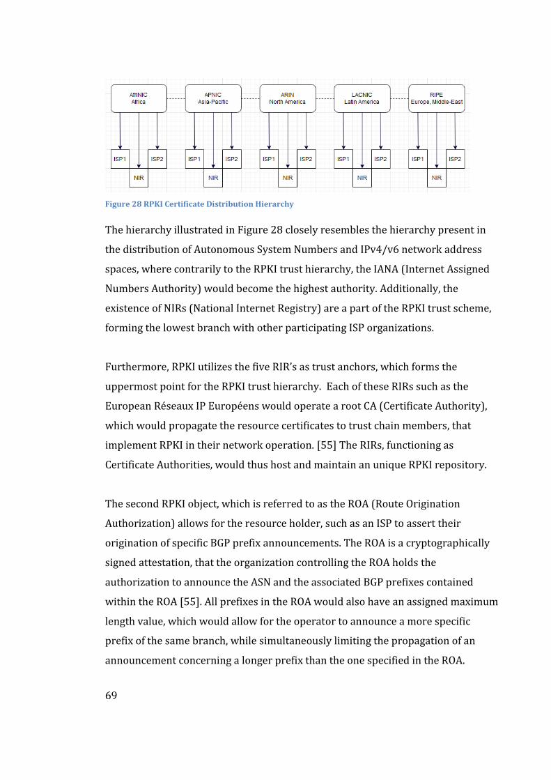
69
Figure 28 RPKI Certificate Distribution Hierarchy
The hierarchy illustrated in Figure 28 closely resembles the hierarchy present in
the distribution of Autonomous System Numbers and IPv4/v6 network address
spaces, where contrarily to the RPKI trust hierarchy, the IANA (Internet Assigned
Numbers Authority) would become the highest authority. Additionally, the
existence of NIRs (National Internet Registry) are a part of the RPKI trust scheme,
forming the lowest branch with other participating ISP organizations.
Furthermore, RPKI utilizes the five RIR’s as trust anchors, which forms the
uppermost point for the RPKI trust hierarchy. Each of these RIRs such as the
European Réseaux IP Européens would operate a root CA (Certificate Authority),
which would propagate the resource certificates to trust chain members, that
implement RPKI in their network operation. [55] The RIRs, functioning as
Certificate Authorities, would thus host and maintain an unique RPKI repository.
The second RPKI object, which is referred to as the ROA (Route Origination
Authorization) allows for the resource holder, such as an ISP to assert their
origination of specific BGP prefix announcements. The ROA is a cryptographically
signed attestation, that the organization controlling the ROA holds the
authorization to announce the ASN and the associated BGP prefixes contained
within the ROA [55]. All prefixes in the ROA would also have an assigned maximum
length value, which would allow for the operator to announce a more specific
prefix of the same branch, while simultaneously limiting the propagation of an
announcement concerning a longer prefix than the one specified in the ROA.
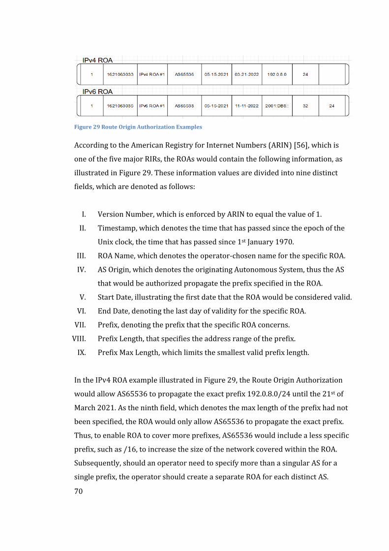
70
Figure 29 Route Origin Authorization Examples
According to the American Registry for Internet Numbers (ARIN) [56], which is
one of the five major RIRs, the ROAs would contain the following information, as
illustrated in Figure 29. These information values are divided into nine distinct
fields, which are denoted as follows:
I. Version Number, which is enforced by ARIN to equal the value of 1.
II. Timestamp, which denotes the time that has passed since the epoch of the
Unix clock, the time that has passed since 1st January 1970.
III. ROA Name, which denotes the operator-chosen name for the specific ROA.
IV. AS Origin, which denotes the originating Autonomous System, thus the AS
that would be authorized propagate the prefix specified in the ROA.
V. Start Date, illustrating the first date that the ROA would be considered valid.
VI. End Date, denoting the last day of validity for the specific ROA.
VII. Prefix, denoting the prefix that the specific ROA concerns.
VIII. Prefix Length, that specifies the address range of the prefix.
IX. Prefix Max Length, which limits the smallest valid prefix length.
In the IPv4 ROA example illustrated in Figure 29, the Route Origin Authorization
would allow AS65536 to propagate the exact prefix 192.0.8.0/24 until the 21st of
March 2021. As the ninth field, which denotes the max length of the prefix had not
been specified, the ROA would only allow AS65536 to propagate the exact prefix.
Thus, to enable ROA to cover more prefixes, AS65536 would include a less specific
prefix, such as /16, to increase the size of the network covered within the ROA.
Subsequently, should an operator need to specify more than a singular AS for a
single prefix, the operator should create a separate ROA for each distinct AS.
71
5.1.1 Deployment of RPKI
In the implementation of RPKI, there exists two distinct methods which are
distinguished from each other, on the basis of whether the deploying organization
wishes to control the CA (Certificate Authority) on their systems. Thus, two
distinctive deployment methods exist for an Autonomous System to choose from.
Hosted RPKI relies upon the Regional Internet Registries, which host centralized
RPKI services thus not requiring the partaking Autonomous System to operate a
sub-CA. The European RIR, which is referred to as the RIPE NCC offers a web-
based RPKI management interface, which allows the organization to manage and
request ROAs. These ROAs would then be hosted and published in servers
operated by the appropriate RIR, while additional services such as automatically
renewing ROAs and suggestions regarding BGP route collectors such as the RIPE
Routing Information Service [57] can vary between the five RIRs.
For larger and more complex Autonomous Systems, the proposition of running a
delegated RPKI solution may become preferable, as this approach allows for a
more hands-on approach to managing the sub-CA. [55] The delegated model
separates the object signing of the RPKI objects from the publishment of the
cryptographic material, thus allowing the organization to publish or sub-contract
the signing of the Certificate Authority-related materials without intervention.
To draw a high-level functional basis of the operation and deployment of RPKI in a
BGP Route Origin Validation-role, we will use the network topology present in
Figure 30, which will utilize the following pre-existing network resources:
- X86-64-based virtual machine, with the Ubuntu 21.04 Linux OS-distribution
and the concurrent version of RIPE NCC’s “RPKI Validator”.
- 2 x Juniper Networks MX480 (Junos OS 20.2R2-S3) & 2 x MX2020 (Junos OS
20.1R1-S4) routers, functioning as ASBRs and Core Routers, respectively.
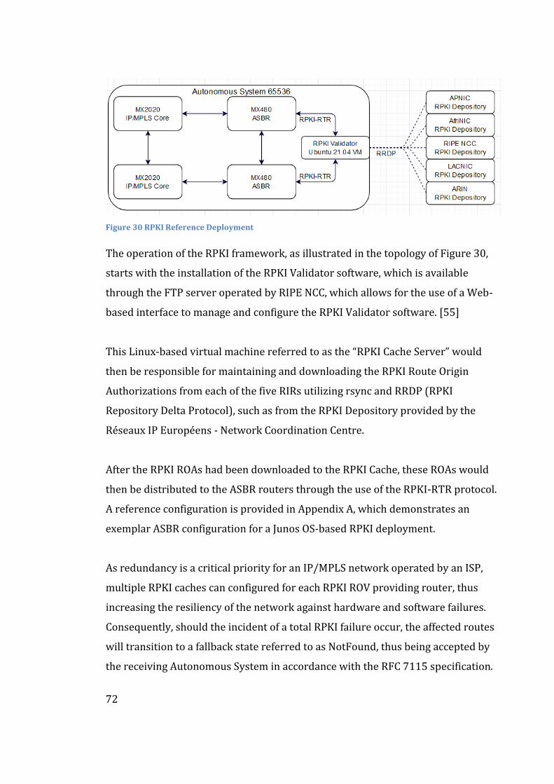
72
Figure 30 RPKI Reference Deployment
The operation of the RPKI framework, as illustrated in the topology of Figure 30,
starts with the installation of the RPKI Validator software, which is available
through the FTP server operated by RIPE NCC, which allows for the use of a Web-
based interface to manage and configure the RPKI Validator software. [55]
This Linux-based virtual machine referred to as the “RPKI Cache Server” would
then be responsible for maintaining and downloading the RPKI Route Origin
Authorizations from each of the five RIRs utilizing rsync and RRDP (RPKI
Repository Delta Protocol), such as from the RPKI Depository provided by the
Réseaux IP Européens - Network Coordination Centre.
After the RPKI ROAs had been downloaded to the RPKI Cache, these ROAs would
then be distributed to the ASBR routers through the use of the RPKI-RTR protocol.
A reference configuration is provided in Appendix A, which demonstrates an
exemplar ASBR configuration for a Junos OS-based RPKI deployment.
As redundancy is a critical priority for an IP/MPLS network operated by an ISP,
multiple RPKI caches can configured for each RPKI ROV providing router, thus
increasing the resiliency of the network against hardware and software failures.
Consequently, should the incident of a total RPKI failure occur, the affected routes
will transition to a fallback state referred to as NotFound, thus being accepted by
the receiving Autonomous System in accordance with the RFC 7115 specification.
73
5.1.2 Operation of RPKI
The Autonomous Systems that participate in the RPKI framework can utilize
various software solutions to monitor the RPKI resources, which are often referred
to as RPs (Relying Parties), such as OctoRPKI and Routinator to ensure the proper
operation of the associated RPKI objects. [58] These software solutions are used to
construct a network object referred to as a VRP or a “Validated ROA Payload”,
which contains the ASN number, the ROA prefix and two attributes related to the
associated prefix, namely the length and maximum length of the prefix. These
VRP objects would then be distributed to the routers in the network.
The integration of RPKI into the operation of an IP/MPLS-enabled router can be
seen in the processing of the BGP announcement, where the router would attempt
to validate the received announcement against the available VRPs it has received
from the Relying Party. This validation process would function as follows
according to Aben, Choffness, Mags et al. [58]:
- Verify whether the announced IP prefix belongs to a certain VRP.
- Verify whether the BGP announcement matches the received VRP, where
the validity requirements such as the IP prefixes, Autonomous System
Numbers, and the length of the announcement versus the maximum length,
match between the BGP and VRP entities.
Following the above method, the router would then ratify the result of the RPKI
validation with three validity states according to Aben, Choffness, Mags et al. [58]:
- Valid: The BGP announcement and the VRP are valid, match is found.
- Invalid: No IP Prefix match for VRP within the BGP announcement, but a
VRP match for the BGP announcement exists.
- Unknown, where no match is found between the BGP announcement and
the available VRPs.
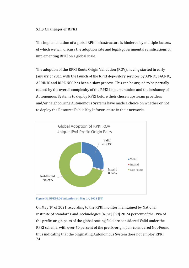
74
5.1.3 Challenges of RPKI
The implementation of a global RPKI infrastructure is hindered by multiple factors,
of which we will discuss the adoption rate and legal/governmental ramifications of
implementing RPKI on a global scale.
The adoption of the RPKI Route Origin Validation (ROV), having started in early
January of 2011 with the launch of the RPKI depository services by APNIC, LACNIC,
AFRINIC and RIPE NCC has been a slow process. This can be argued to be partially
caused by the overall complexity of the RPKI implementation and the hesitancy of
Autonomous Systems to deploy RPKI before their chosen upstream providers
and/or neighbouring Autonomous Systems have made a choice on whether or not
to deploy the Resource Public Key Infrastructure in their networks.
Figure 31 RPKI-ROV Adoption on May 1st, 2021 [59]
On May 1st of 2021, according to the RPKI monitor maintained by National
Institute of Standards and Technologies (NIST) [59] 28.74 percent of the IPv4 of
the prefix-origin pairs of the global routing field are considered Valid under the
RPKI scheme, with over 70 percent of the prefix-origin pair considered Not-Found,
thus indicating that the originating Autonomous System does not employ RPKI.
Valid28.74%
Invalid0.56%
Not-Found70.69%
Global Adoption of RPKI ROVUnique IPv4 Prefix-Origin Pairs
Valid
Invalid
Not-Found
75
The adoption rate of RPKI has increased in the recent years however, as
exemplified with the RPKI ROV adoption by Lumen (formerly known as Level3)
[60], which operates the largest worldwide transit backbone network under the
Autonomous System 3356, which occurred recently in early spring of 2021. As
larger Tier 1 networks e.g., Lumen and larger content providers e.g., Google LLC
[61] and Netflix [62] adopt RPKI, the overall adoption rate of RPKI is expected to
rise exponentially in the following years, thus increasing the overall proactive
security of the BGP routing process worldwide.
The second argument against a global deployment of RPKI, which concerns the
power of the governmental and legal actors against the trust anchor RIRs. All RIRs
exist under the jurisdiction of a host country, such as Netherlands in the case of the
European RIPE. This introduces a critical problem due to the fact that local
authorities can and have forced the modification of ROA’s associated with certain
prefixes in 2011 [63], thus illustrating a weakness in the RPKI architecture. As
these RIR’s have the full authority and power to change and revoke all ROAs issued
by them to any ISP, the problem of governmentally caused invalidation of BGP
routes can become critical aspects in governmental censorship and cyberwarfare.
Proposals have been made to reduce the amount of power RIRs hold over the RPKI
architecture, such as with the proposal by Shrishak & Shulman [64]. This proposal
limits the power given to the RIR’s by introducing a concept called MPC (Multi-
Party Computation), which distributes RPKI threshold signatures, which separates
the private key used to sign an ROA between the five RIR’s, thus limiting the power
of a singular RIR in the RPKI framework. Consequently, as a result of removing the
ability of a single RIR to modify ROAs or Certification Revocation Lists (CRLs), the
legal vulnerability of the RPKI architecture is reduced as the legal process would
need to compel all five RIR’s to comply with the order. [64] Therefore, as no single
RPKI authority would hold the full private key to the RPKI architecture, the overall
strength of the RPKI model is increased as no actor would be trusted completely,
illustrated by the lack of a complete private key in their possession.
76
5.2 Reactive Mitigation: Artemis
This chapter covers the practical implementation of the Artemis BGP monitoring
tool, which stands to improve the detection and automatic mitigation of BGP Prefix
hijacking attacks. The deployment of Artemis within the IP/MPLS network of
Autonomous System 16086 is proposed, utilizing the BGP routing information
streams from sources such as the RIPE NCC’s Route Information Service.
5.2.1 Background & Function
Named after the goddess of the hunt from the Greek pantheon, Artemis
(“Automatic and Real-Time dEtection and MItigation System”) is the proposed
solution of this thesis to the reactive security of BGP prefixes. As proposed by
Sermpezis, Kotronis, Gigis et al. [65] Artemis focuses on five factors of
implementing a reactive mitigation against BGP prefix hijacking, particularly the
evasion, accuracy, speed, flexibility, and privacy of such a solution.
One of the issues in implementing an automatic prefix hijacking mitigation tool is
the sophistication of the hijacking attacks, thus requiring a diverse classification
scheme in order to prevent any attacks from falling through the gaps. Sermpezis,
Kotronis, Vasileios et al. propose a modular taxonomy that categorizes BGP hijack
variants under specific sub-categories. Considering the case study covered
previously on this thesis in section 3.2.2 that examined the incident in 2008 with
Pakistan Telecom, the Artemis tool would refer to the classification scheme
illustrated in Appendix C, resulting in a “E|1|-|- “-hijack classification.
The accuracy of an automatic solution in the detection and mitigation of a hijacking
incident is a critical aspect, due to the need to avoid false positive incidents.
These false positives can occur due to a recent addition of a BGP peer or a more
sophisticated traffic engineering solution, such as announcing a more specific BGP
prefix. Thus, Artemis proposes the use of distinct BGP feeds to allow for the
77
automatic updates to the database of BGP prefixes, without requiring any human
intervention in this process. These feeds, such as the BGPmon, Routeviews and the
RIPE Routing Information System streaming services are offered by their
respective organizations, which utilize multiple route collectors to build a database
of all live BGP prefixes on the Internet. [65]
The speed of the Artemis solution can be considered one of it is strong suits as the
fully automatic threat detection and single-action threat mitigation techniques will
decrease the number of human resources required to implement a mitigation
against a BGP hijacking attack according to Sermpezis, Kotronis, et al. [65]
As for the privacy of the Artemis solution, the authors propose that a self-hosted
solution is available, which would by definition increase the security of the system.
In the world of ISP networks for example, the privacy-related concerns with the
public disclosure of BGP peering policies and prefixes for example can be a concern
for a network operator which could inhibit the adoption of BGP prefix monitoring
tools such as the proposed Artemis tool. [65]
The flexibility of the Artemis system stems from local operation ability in addition
to a third-party deployment, which allows the network operator to choose from
various different deployment scenarios, such as customizing the mitigation efforts
against specific prefixes and attack classes.
Artemis is argued to be able to detect and mitigate a BGP hijacking attack within
seconds and minutes, respectively. These resolution times are to be considered an
improvement to the current practises, such as manual detection and mitigating
configurations can take more time than the comparative single-step mitigation,
which is achieved through the use of the Artemis tool.
As the SLA requirements of an ISP’s core network are often high, the quick
mitigation of an BGP hijack attack can mean the difference between the ISP
78
meeting the strict SLA requirements posed to them by their customers or not.
Thus, it could be argued that after deployment and proper configuration, Artemis
can decrease the amount of SLA sanctions imposed on the network operator, as
these BGP route convergence-related outages would be reduced considerably.
The function of the Artemis BGP tool can be divided into three phases: live BGP
update monitoring, threat detection and threat mitigation, of which the latter
requires human intervention by default, although an automatic mitigation feature
is also present in the Artemis tool through the integration of the ExaBGP tool.
The monitoring phase operates using BGP prefix updates, which from the
perspective of Artemis are critically reliant on the previously mentioned BGP data
feeds, such as the BGPmon service provided by the Colorado State University and
the RIS (Routing Information System) provided by RIPE NCC. Artemis uses these
information feeds to detect changes in the propagation of BGP prefixes, such as
new BGP announcements or BGP route withdrawals.
The hijacking detection process is reliant on the interaction between the local
configuration file and the previously mentioned BGP feeds, which contain BGP AS-
PATHs and prefixes. [65] The received updates are compared to the local
configuration file, such as the one illustrated in Appendix B, which contains a list of
the following parameters:
- Owned Autonomous System Numbers (e.g., AS65536)
- Owned BGP prefixes (e.g., 10.0.88.0/16)
- Neighbouring ASNs (e.g., AS65536, AS65538)
- Routing Policy (e.g., Prefix A is announced by AS64514 to AS64516)
This configuration file can either be manually configured or integrated to the
network to allow for an automatic configuration update process, such as through
the interaction of the network’s route reflectors and the iBGP protocol.
79
Considering the mitigation of BGP hijacking incidents, Sermpezis, Kotronis,
Vasileios et al. [65] propose two distinct mitigation measures, which are referred
to as BGP prefix deaggregation and third-party mitigation, where the latter utilizes
a third-party DDOS (Distributed Denial of Service) mitigation provider.
The first mitigation, which is referred to as BGP prefix deaggregation functions on
the basis that the Autonomous System suffering from a BGP hijacking attack
initiates the propagation of a more specific prefix than the hijacked prefix. In
practicality, should the prefix 10.0.0.0/22 be hijacked, the mitigating party should
propagate prefix such as 10.0.0.0/23 and 10.0.1.0/24 in order to leverage the
longest prefix match rule in the BGP routing decision process.
After the propagation of the more-specific prefixes, the autonomous systems that
had accepted the propagation of the hijacked prefix would re-ascertain the
legitimate route, thus rerouting the affected traffic back to the mitigating party.
This mitigation method has its limitations however, as network routers often place
filters on prefixes that exceed the specificity of /24, thus rejecting the traffic from a
prefix such as 10.0.0.0/25. A practical example can be seen in the public transit
policy of Elisa Corporation. [27], a Finnish ISP which treats prefixes that are longer
than /22 and /24 as harmful. Elisa does offer an exception for /24 routes on a
singular network (192.0.0.0/7), which is referred to as the “Swamp”.
To automate the process of mitigating a BGP hijacking attack through the use of
BGP prefix deaggregation, Sermpezis, Kotronis, Vasileios et al. [65] propose the use
of the ExaBGP tool, or alternatively the use of a deployment-specific script.
ExaBGP is a Python-based tool that converts BGP messages to either a plain text or
a JSON format as an implementation of SDN (Software Defined Networking). [66]
Thus, with the integration of ExaBGP, Artemis enables the integration to a pre-
existing OSS (Operations Support System) and BSS (Business Support System)
systems into the automatic BGP hijack mitigation process.
80
The process of utilizing ExaBGP additionally be used to generate and propagate
Flow Routes in accordance with the RFC 5575 by Marques, Sheth, Greene et al.
[67], which allows for the injection of BGP routes. This process can be used to
initiate a RTBH (Remotely Triggered Blackholing) defence against such attacks
BGP hijack attacks, although this defensive measure is to be used with caution.
The second mitigation measure proposed by Sermpezis, Kotronis, Vasileios et al.
[65] is the use of a third-party mitigation organization, which can be achieved with
efforts such as the outsourcing of the BGP announcements, through the use of BGP
MOAS (Multiple Origin Autonomous System) which allows the third-party
organization to propagate the outsourced prefix simultaneously with the
originating Autonomous System.
Through the use of the notification ability in Artemis, the third-party mitigation
organization would then receive the notification about an ongoing BGP hijacking
event, thus simultaneously initiating the process of mitigating the attack. [65]
When the mitigating party would start the propagation of the hijacked prefix, the
affected traffic would begin to be rerouted towards their data centres, which is
achieved through of the BGP shortest AS-PATH rule.
In order to redirect the aforementioned traffic back to the legitimate owner, the
mitigating party could use MPLS-based tunnels to the affected Autonomous System
or alternatively to the upstream providers of the same AS. The use of a direct
peering link, such as a Layer 3 MC-LAG NNI, should one be available between the
two contracted parties, can be utilized for the return of the rerouted traffic, which
can be a more OPEX-efficient solution. The efficiency of the aforementioned
solution would be illustrated when the amount of rerouted traffic would exceed
levels that would prohibitively increase OPEX spending caused by transit costs, for
example.
81
5.2.2 Adoption of Artemis
The deployment of the Artemis requires a Unix-based operating system, such as
the Ubuntu 21.04 operating system this thesis utilized as the RIPE NCC RPKI
validator in the topology of Figure 30 in section 5.1.1, although other Linux
distributions such as Mint and RHEL (Red Hat Enterprise Linux) will suffice as
well. To ensure the proper function of the Artemis tool, Sermpezis, Kotronis,
Vasileios et al. [65] recommend the availability of the following hardware
resources for optimal operation:
- 4+ CPU cores, dependent on the number of separate processes.
- 4+ GB of RAM, dependent on the complexity of the network, the amount of
incoming BGP updates and number of prefixes & rules.
- 50 GB of storage space, which is dependent on the amount of BGP updates
the network operator wishes to store at a time.
- 1 x Internet facing network interface (+n local network interfaces)
- Docker-ce and docker-compose software packages, with sudo (super-user)
privileges.
- SSH server, to enable remote connectivity to the server.
For the purposes of this thesis, we will assume that the deploying organization
uses a machine that exceeds to previously mentioned requirements, thus nullifying
the effect of inadequate hardware on the proposed Artemis implementation.
As the deployment of Artemis into the network of an Internet Service Provider
requires redundant and fault-resilient operation, best practises regarding the
deployment of the Artemis tool must be considered before the initial deployment
phase. One such aspect, the introduction of multiple local monitor instances inside
the network of an Autonomous System would require the provision of secondary
network interfaces on the Artemis host device, thus increasing the hardware
requirements of the Artemis host.
82
In the deployment of the Artemis tool, the only networking port that is
necessitated by a reference installation, is the de-facto standard HTTPS port 443.
Thus, the network operator can create firewall rules that would deny all traffic
towards the Artemis host, with the notable exception of the HTTPS port 443. [65]
Thereafter, the attack surface of Artemis that is exposed towards the Internet
would be minimized, which increases the overall security of the system.
Further considering the security aspects of such a deployment, a network
administrator should allocate an internal IP address provided through a NAT
translation e.g., 192.168.0.X for the Artemis host, which restricts access from
outside of the deploying AS. [65] As the public facing network interface is only
required for communication with external BGP monitors such as RIPE NCC’s RIS,
the Artemis host machine does not strictly require a public IP address.
The redundancy of Artemis from a software perspective can be achieved in a
similar fashion as a Layer 3 MC-LAG NNI, with two separate nodes that provide
hardware redundancy for one another. Thus, a multi-homed deployment of
Artemis can provide a redundant BGP hijack detection scheme, provided that the
Artemis hosts are located in separate prefixes. This separation is made to ensure
that should a prefix containing the first Artemis deployment be hijacked and thus
rendered unusable, the second instance would still be able initiate the mitigation
measures, such as leveraging an ExaBGP script to recover the affected prefix.
In the case of a connectivity failure between the AS and the external monitor, such
as in a case of a blackholing hijacking incident, the availability of multiple local
monitors can further increase the resiliency of the Artemis deployment against
such attacks. [65] In the aforementioned scenario, Artemis would still be able to
gather information about BGP updates within the network without the existence of
an external monitor, thus increasing the resilience of the solution. In practical
terms, this approach would allow the Artemis tool to detect an BGP hijack that
would affect the prefix Artemis itself resides in.
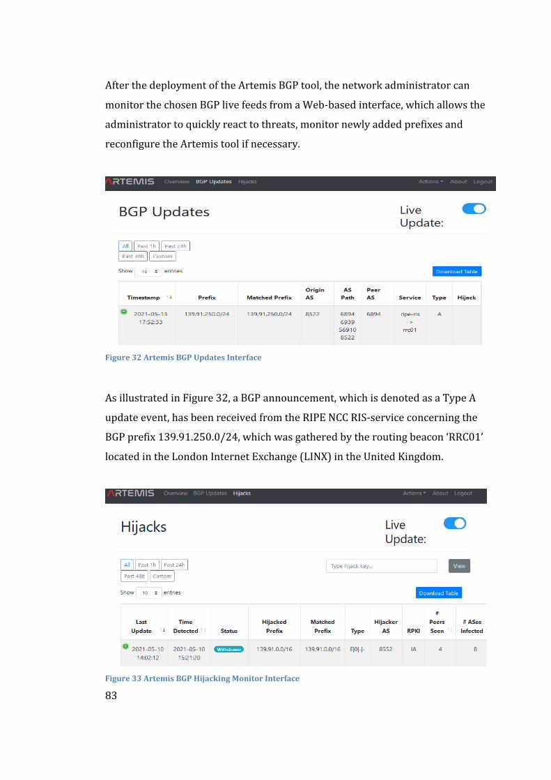
83
After the deployment of the Artemis BGP tool, the network administrator can
monitor the chosen BGP live feeds from a Web-based interface, which allows the
administrator to quickly react to threats, monitor newly added prefixes and
reconfigure the Artemis tool if necessary.
Figure 32 Artemis BGP Updates Interface
As illustrated in Figure 32, a BGP announcement, which is denoted as a Type A
update event, has been received from the RIPE NCC RIS-service concerning the
BGP prefix 139.91.250.0/24, which was gathered by the routing beacon ‘RRC01’
located in the London Internet Exchange (LINX) in the United Kingdom.
Figure 33 Artemis BGP Hijacking Monitor Interface
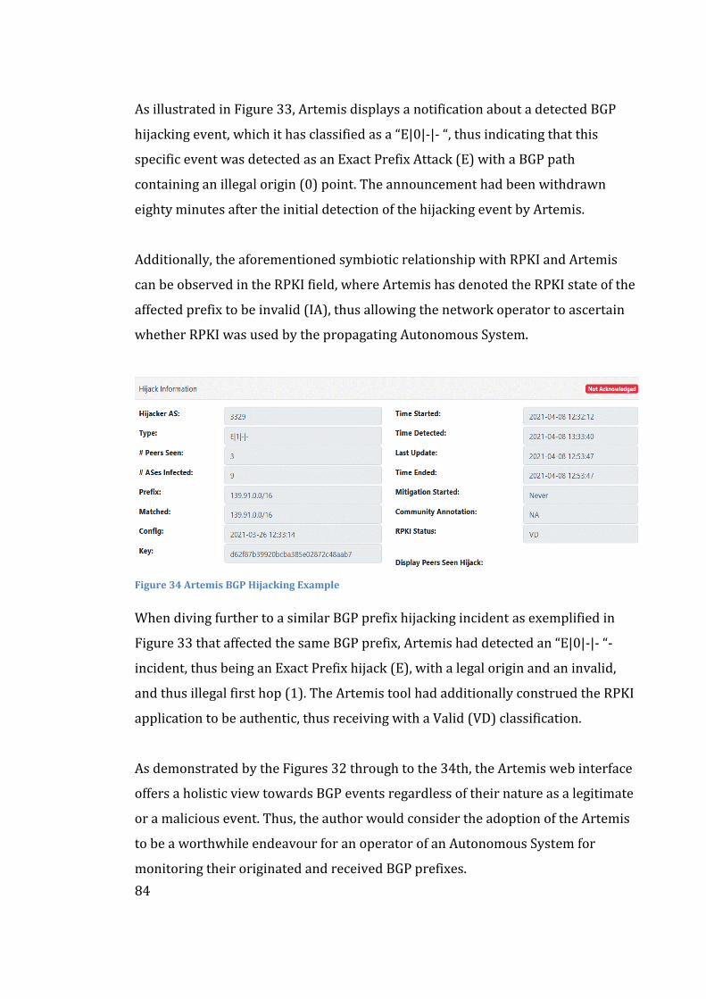
84
As illustrated in Figure 33, Artemis displays a notification about a detected BGP
hijacking event, which it has classified as a “E|0|-|- “, thus indicating that this
specific event was detected as an Exact Prefix Attack (E) with a BGP path
containing an illegal origin (0) point. The announcement had been withdrawn
eighty minutes after the initial detection of the hijacking event by Artemis.
Additionally, the aforementioned symbiotic relationship with RPKI and Artemis
can be observed in the RPKI field, where Artemis has denoted the RPKI state of the
affected prefix to be invalid (IA), thus allowing the network operator to ascertain
whether RPKI was used by the propagating Autonomous System.
Figure 34 Artemis BGP Hijacking Example
When diving further to a similar BGP prefix hijacking incident as exemplified in
Figure 33 that affected the same BGP prefix, Artemis had detected an “E|0|-|- “-
incident, thus being an Exact Prefix hijack (E), with a legal origin and an invalid,
and thus illegal first hop (1). The Artemis tool had additionally construed the RPKI
application to be authentic, thus receiving with a Valid (VD) classification.
As demonstrated by the Figures 32 through to the 34th, the Artemis web interface
offers a holistic view towards BGP events regardless of their nature as a legitimate
or a malicious event. Thus, the author would consider the adoption of the Artemis
to be a worthwhile endeavour for an operator of an Autonomous System for
monitoring their originated and received BGP prefixes.
85
5.2.3 Network Integration
The integration of the Artemis BGP tool into an IP/MPLS-based network has
multiple vectors to consider in the integration process, such as the deployment
(installation), notification, and mitigation measures. A reference configuration for
the high-level deployment of Artemis is illustrated in Appendix D.
As Artemis does not require dedicated hardware for its operation, a network
operator could utilize existing hardware virtualization infrastructure. Thus, the
usage of pre-existing virtualized hardware allows for a CAPEX and OPEX efficient
implementation of Artemis alongside other virtualized network resources as no
dedicated hardware would be required to deploy Artemis to their network.
Actualizing the benefits of Artemis’s detection capabilities requires an efficient
way of communicating information about any events to the applicable parties, such
as the core transmission network design and operation groups. Additionally, the
NOC (Network Operations Centre) and SOC (Security Operations Centre) need to
be notified about high-severity incidents, as the communication with other
Autonomous Systems is critical in mitigating BGP hijacking incidents.
Thus, as Artemis allows for an email and logging-based automatic notification
scheme, the author proposes that an email-based notification is to be sent to the
previously mentioned groups until a more efficient system integration with the
network monitoring software ecosystem is developed within the Autonomous
System choosing to deploy Artemis within their network.
In the mitigation of BGP hijacks detected by Artemis, as previously mentioned, the
operating ISP would need to create a customized script or employ an additional
software such as the Exa-BGP solutions mentioned in the previous section.
Therefore, the implementation of Artemis would require additional work from a
network engineering team to enable the automatic mitigation feature of Artemis.
86
5.3 The Future: BGPsec
This section covers the BGPsec extension, which aims to increase the overall
security of BGP operation in collaboration with the RPKI architecture. Keeping in
mind the developments made by the SIDR (Secure Inter-Domain Routing) Working
Group on BGPsec, this thesis discusses the feature to form a futuristic perspective
into considerations regarding the implementation of BGPsec, should it be adopted
within an Autonomous System in the future.
5.3.1 The Promise of BGPsec
Based on the work made by the Internet Engineering Task Force Secure Inter-
Domain Routing Working Group and the example set by S-BGP (Secure-BGP),
BGPsec introduces a cryptographically signed chain, which aims to validate the
path a BGP prefix would travel between different Autonomous Systems. Thus, as
defined in IETF RFC 8205 by Lepinski & Sriram [68] BGPsec aims to ensure that all
the Autonomous Systems on the AS-PATH have explicitly allowed the propagation
of the BGP prefix to the consequent Autonomous System.
The BGPsec extension is reliant on the operation of a pre-existing Resource Public
Key Infrastructure (RPKI) implementation, as BGPsec utilizes the prefix origin
authentication provided by RPKI, namely the Route Origin Authorization object.
Additionally, considerations for the deployment and migration of BGPsec have
been made with multiple RFC specifications. Additional proposed standards, such
as RFC 8635 by Bush, Turner & Patel considered the keying of routers for the use
of BGPsec. Consequently, the assertation could be made that BGPsec is still in a
developmental phase, hindered by multiple factors such as the heavy processing
load on the BGP-enabled routers and the practical impossibility of an incremental
deployment of the feature within an Autonomous System.
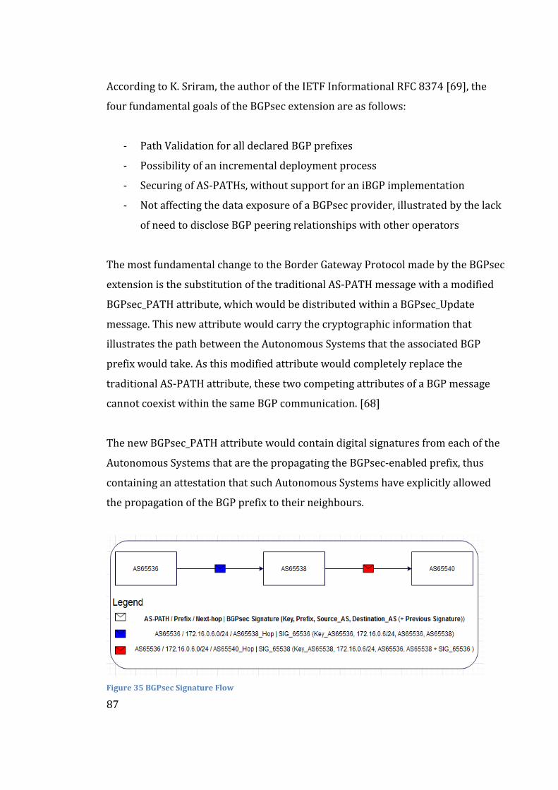
87
According to K. Sriram, the author of the IETF Informational RFC 8374 [69], the
four fundamental goals of the BGPsec extension are as follows:
- Path Validation for all declared BGP prefixes
- Possibility of an incremental deployment process
- Securing of AS-PATHs, without support for an iBGP implementation
- Not affecting the data exposure of a BGPsec provider, illustrated by the lack
of need to disclose BGP peering relationships with other operators
The most fundamental change to the Border Gateway Protocol made by the BGPsec
extension is the substitution of the traditional AS-PATH message with a modified
BGPsec_PATH attribute, which would be distributed within a BGPsec_Update
message. This new attribute would carry the cryptographic information that
illustrates the path between the Autonomous Systems that the associated BGP
prefix would take. As this modified attribute would completely replace the
traditional AS-PATH attribute, these two competing attributes of a BGP message
cannot coexist within the same BGP communication. [68]
The new BGPsec_PATH attribute would contain digital signatures from each of the
Autonomous Systems that are the propagating the BGPsec-enabled prefix, thus
containing an attestation that such Autonomous Systems have explicitly allowed
the propagation of the BGP prefix to their neighbours.
Figure 35 BGPsec Signature Flow
88
With the high-level illustration of the BGPsec signature process illustrated in
Figure 35, BGPsec would be able to verify the integrity of the BGP messaging,
through the inclusion of the fields presented within the BGPsec_PATH message.
Thus, as illustrated in Figure 35, the Autonomous System 65412 sends a traffic
flow towards AS65416, with AS65414 acting as the intermediary, or transit
provider. The following BGPsec-PATH message would contain the following
information:
- AS-PATH of the prefix, e.g., AS65536, AS65538.
- BGP prefix e.g., 172.16.6.0/24.
- Next-hop e.g., 10.0.1.0/24.
- BGPsec Signature, consisting of a Key, Prefix, Source AS, Destination AS, and
previous BGPsec signatures from any preceding Autonomous Systems.
From a practical perspective using the topology of Figure 35, the BGPsec signature
would contain the private key of signing AS (AS65536), prefix (172.16.6.0/24),
source ASN (AS65536) and destination ASN (AS65338) fields in communications
between AS65536 and AS65538. [70] Furthermore, utilizing the topology of Figure
35, the second scenario illustrated on the right-hand side of the aforementioned
figure displays the interlocking modification of the BGPsec signature. In the
communication between AS65536 and AS65540, the signature of the AS65536
would be included in the concluding section of the BGPsec signature of AS65538.
Therefore, as the BGPsec signature would expand with each Autonomous System
adding their signature to the affected prefix, thus effectively verifying the entirety
of the AS-PATH travelled by the prefix. Thus, BGPsec would effectively implement
BGP Path-Validation, which is not currently possible with the Resource Public Key
Infrastructure implementation. Thus, as BGPsec does require RPKI in order to
function, the symbiotic implementation of these technologies is proposed after
vendors, such as Juniper Networks provide efficient implementations of BGPsec.
89
Due to the relatively recent development of BGPsec, multiple variations of the base
implementation have been proposed as to further the increase the overall security
of a network employing BGPsec. Recently, one such proposal was published in the
IEEE Network Journal. The research paper from Li, Liu, Hy, Xu and Wu [71]
proposes two methods of increasing the overall security of BGPsec extension.
The first proposal by Li, Liu, Hy, Xu and Wu [71] argues that BGPsec would be
enhanced through the introduction of certificate for physical links in addition to
the Route Origin Authorizations provided by RPKI. With this physical link
certificate, a router could verify the authenticity of the physical links on the chosen
BGP prefix, thus reducing the feasibility of multiple attacks against the routing
process, which the authors refer to as “Mole” and “Tiger” attacks.
The second improvement to BGPsec proposed by Li, Liu, Hy, Xu and Wu would
leverage the existence of trusted computing in existing processor architectures,
such as the Intel SGX (Software Guard Extensions). [71] As a hardware-oriented
method of securing BGPsec, the introduction of trusted computing to a BGP router
would effectively restrict access to protected memory regions of the router, thus
decreasing the feasibility of a routing protocol manipulation attack.
From a practical perspective, as the hardware capabilities of the routing platform
vendors have increased, thanks to the improvements made in the design of
processor microarchitectures by vendors such as AMD and Intel. The increased
capability of these next-generation routers can be illustrated with the introduction
of the PTX 10000-series routing platforms [72] by Juniper Networks.
The promise of BGPsec, while a distant one due to the limitations described in the
following section, can be construed as to be within reach. As recent developments
in the optimization of the BGPsec implementation and the multi-core processing
capabilities of the next-generation IP/MPLS routing platforms, the processing
power limitation of BGPsec can hopefully be mitigated in the near future.
90
5.3.2 Challenges of BGPsec
This section will cover most well-known problems associated with the use of
BGPsec, including the increased amount of routing platform resource and other
considerations, such as the increased convergence time introduced by BGPsec.
This focus on the cumulative increase in the convergence time of BGP will tie back
to the first research objective of this thesis, BPG Prefix Independent Convergence
which aims to decrease the amount of time needed for said BGP convergence.
The challenging nature of the BGPsec’s current implementation cannot be
understated however, as changes to the fundamental architecture and operation of
the Border Gateway Protocol make the implementation of BGPsec a challenging
proposition for any Autonomous System.
As a practical example, the inherent requirement of adding a new cryptographical
BGP prefix verification step to each BGPsec-enabled IP/MPLS router would
increase the processing load of the router’s CPU (Central Processing Unit)
drastically when compared to traditional BGP operation.
In addition to the increased amount of processing and memory required for a
BGPsec enabled router, the implementation of BGPsec is currently hindered by the
lack of support from various IP/MPLS routing platform vendors. As such, the
implementation of BGPsec will require solutions for the aforementioned issues
before such an implementation would become a valuable proposition.
In the presentation given by Adalier, Sriram et al. [73] at the 2017 NANOG-69
conference in Washington D.C., a practical demonstration utilized a singular
processing core of an Intel Xeon® E3-1285v4 CPU, based on the Broadwell
microarchitecture, to demonstrate the increased CPU load caused by the use of
BGPsec. The aforementioned presenters defined the two following scenarios to be
equivalent to the operation of a “Large Global ISP”.
91
The first scenario illustrated the added CPU time needed for the aforementioned
processor to revalidate the BGPsec session, which for approximately 30,750
BGPsec prefixes would require 3.11 seconds of CPU time from the aforementioned
Xeon-processor in order to revalidate the affected prefixes. The second scenario
presented by Adalier, Sriram et al. concluded that in the scenario where the
aforementioned processor would need to both validate and sign approximately
30,750 BGPsec prefixes, the required amount of CPU time required for such an
operation would increase to 5.54 seconds. [73]
The second major disadvantage of a state-of-art BGPsec implementation in
addition to the amount of added processing time, is the increased amount of
memory consumption. Takemura, Okada, Okamura et al. [74] note in their
research on APVAS, which aims to reduce the aforementioned memory usage of
BGPSec, that a full BGPsec routing table would require over 10 Gigabytes of RAM
memory from the BGPsec enabled router. This requirement effectively prevents a
network operator from utilizing second-rate IP/MPLS routing platforms, as they
will not be able to fulfil the aforementioned memory requirement.
Consequently, a network operator might choose to utilize a brute-force approach
to this requirement, through choosing a routing platform such as PTX 10000-series
by Juniper Networks, which offers a “JNP10K-RE1-128 Routing Engine” with 128
Gigabytes of RAM (Random Access Memory) [72]. As such a brute-force approach
is an extremely CAPEX-inefficient way of dealing with the problem, a more
memory-efficient BGPsec implementation is required.
The proposal by Takemura, Okada, Okamura et al. [74] proposes a new AS-PATH
validation scheme stemming from the use of aggregate signatures, which are used
to concentrate singular BGPsec signatures into a short aggregate signature, thus
effectively reducing the amount of memory required in the operation of BGPSec.
Takemura, Okada, Okamura et al. [74] claim to have achieved an 80 percent
reduction in memory footprint in the propagation of BGPsec routes.
92
A distinct limitation in the solution to the proposal by Takemura, Okada, Okamura
et al. exists in the fact that the introduction of a bimodal aggregate signature in the
operation of BGPsec does increase ethe overall processing load on the BGPsec-
enabled router when compared to the ECDSA signature in the original BGPsec
proposal. [74] The authors recognize this problem by proposing further studies
that would decrease both the memory consumption and the computational cost of
their APVAS solution, which would improve BGPSec’s efficiency.
When considering the first research topic of this thesis, which concerned the
optimization of the Border Gateway Protocol with the implementation of Prefix
Independent Convergence, this added computational time and processing load can
be problematic for the operation of an IP/MPLS-based Autonomous System.
Introducing a new delay to the overall BGP convergence process is quite
problematic for an ISP due to the aforementioned need to adhere to the strict
requirements of SLA contracts and reducing the impact of routing disruptions in
critical applications, such as redundant connectivity for a medical facility.
Due to the fact that BGPsec update process occurs after the convergence of BGP,
the inclusion of BGPsec can be construed as to increase the overall convergence
time of the BGP protocol stack. This increase in the time required before BGP
convergence, and thus traffic restoration, will become a problematic issue as a
network operator would prefer to minimize the amount of time before traffic
would be restored. Consequently, the implementation of BGPsec can be considered
to be a hinderance in the fulfilment of contractual obligations related to the
aforementioned SLA-agreements and numerous other critical applications.
These improvements, while experimental in their nature, do illustrate an
increasing amount of optimism for the future of BGPsec overall as optimizations
and new algorithms come to the forefront. Thus, the author of this thesis is
optimistic for an efficient future implementation of BGPsec, which would increase
the overall security of the Internet, the network to end all networks.
93
6 Analysis
This section covers the lessons learned during the research process of this thesis.
Considering the thesis research objectives, of which the first was to form a
synopsis of the advanced BGP feature referred to as BGP Prefix Independent
Convergence. The prospective implementations of Resource Public Key
Infrastructure, Artemis BGP monitoring tool and the BGPsec protocol extension
within the Autonomous System 16086 are proposed in the second section.
6.1 Prefix Independent Convergence
The focus on the advanced BGP feature referred to as BGP Prefix Independent
Convergence as a method of increasing the resiliency of an MPLS-based network
proved fruitful as the benefits of the implementation of such a technology would
improve the convergence time in MPLS networks. As the BGP and IGP
convergences are relatively common in a regional fibre transmission network
operated by an ISP, due to reasons such as planned measures e.g., fibre slicing,
cable rerouting and router maintenance, and unplanned measures e.g., accidental
fibre cuts and router ecosystem failures. These incidents would affect the overall
compliance of the Internet Service Provider to the strict Service Level Agreements
which the ISP has contractual obligations to meet as to avoid the sanctions therein.
Thus, BGP Prefix Independent Convergence can be utilized as an indirect cost-
saving measure, as the increased resilience of the MPLS-network could yield a
decrease in the SLA sanctions imposed on them. This improvement is caused by
the decreased time spent on the route convergence process before traffic
restoration would occur. Therefore, the contractual effect of an unplanned
network change e.g., fibre break would be reduced significantly, which would
simultaneously increase the number of unannounced breaks in connectivity
allowed within the uptime requirements of various grades of Service Level
Agreements, to which the ISP would be beholden to.
94
It would be ill-considered to only consider the benefits of the implementation of
BGP Prefix Independent Convergence. While the feature does allow for a more
fault resilient network, multiple challenges such as the interoperability of the BGP
PIC feature between different routing platform vendors and availability of the
feature in network operator’s preferred software versions remain.
The dilemma of interoperability between different implementations of BGP PIC
can become problematic, such as with the deployments that concern a diverse, or
in other words, a multi-vendor network. As vendors such as Cisco Systems and
Juniper Networks support several aspects of the Prefix Independent Convergence
feature set, the implementation of PIC in a multi-vendor IP/MPLS network might
prove problematic in specific circumstances. Therefore, the deployment of a
specific BGP PIC sub-feature might introduce new unforeseen problems in the
interaction between IP/MPLS routing platforms from various hardware vendors.
Although Prefix Independent Convergence does allow an incremental deployment
across an IP/MPLS network according to Bashandy, Filsfils and Mohapatra [52],
the practical deployment of BGP PIC across an entire Autonomous System would
require multiple planned maintenance windows so as to ensure the proper
functioning of the IP/MPLS network during the deployment process.
Due to the relatively common event of fibre maintenance occurring in the physical
network, the network operator needs to choose the deployment schedule
accordingly in order to prevent a complete connections blackout of an entire
regional IP/MPLS router chain, such as the one presented in Figure 20.
In addition to the traditional fibre break caused by an excavator, this break in
connectivity can occur due to a configuration commit which would enable the BGP
PIC feature. As a practical example, the operating system of the router could fail to
commit the configuration without simultaneously causing a route flap to all
connections which are terminated to aforementioned router.
95
The deployment of the PIC feature in the primary router that supplies the
connectivity to a regional chain can risk the connectivity of the entire chain.
Thereafter, a failure of the redundant router for a reason, such as fibre breaks or
hardware failures, could cause an entire region of a country to be disconnected
from the IP/MPLS core network, thus being effectively rendered connectionless.
This network break could cause high financial losses for the customers terminated
within the regional router chain, as they would be effectively severed from the rest
of the IP/MPLS network, and thus the Internet. As an additional concern, a
nationwide ISP often operates multiple base stations which are often terminated to
the aforementioned routers. Therefore, a break in the connectivity to these routers
would cause a simultaneous blackout in the overall mobile coverage within the
region, which would consequently increase the overall effect of such a networking
failure, such as with the effective blockade of emergency calls.
Therefore, as the implementation of BGP Prefix Independent Convergence cannot
be trusted to be completely hitless to the customers terminated to a LSR router,
the involvement of a change management process, such as with the procurement
of service break notifications to the possibly affected customers can prove to be a
beneficial choice for the ISP choosing to deploy BGP Prefix Independent
Convergence across their IP/MPLS network. This process would avoid the
unnecessary use of the sanctioned time for unannounced breaks present in the
strict uptime requirements of high-grade Service Level Agreements.
Nevertheless, the issues of the practicalities associated with the deployment of
BGP Prefix Convergence such as multi-vendor compatibility and scheduling of the
maintenance breaks to preserve connectivity do not overshadow the major
advantage of decreasing the overall BGP convergence time of the network, as the
beforementioned issues would only be present in the deployment phase of the BGP
Prefix Independent Convergence feature, while the benefits of such a deployment
would be visible for a significantly longer.
96
These benefits, such as the two-hundred-fold reduction in the convergence time of
eBGP protocol as observed by Bashandy, Filsfils and Mohapatra [52], which is
illustrated in Figure 24 offer a significant factor in favour of an implementation of
BGP Prefix Independent Convergence within the Autonomous System 16086. This
scenario illustrates that a convergence method, that is not reliant on the serialised
nature of traditional BGP convergence, can decrease the amount of time before
traffic restoration to an extent that will overshadow the time and effort required to
implement and manage the implementation of such a feature.
A simultaneous network-wide implementation however is considered unwise as
the change in the configuration that affects BGP can cause significant BGP “churn”
which would increase the computational load on each router that would deploy
BGP PIC. Due to this reason, the risk of deploying the solution to the entire MPLS
network in a singular maintenance window could prove problematic.
Software failures, such as a crash related to the RPD process in Juniper Network’s
routers, which could cause significant connectivity failures in architecturally
critical devices. Additionally, failures in devices such as BGP Route Reflectors can
cause significant problems in the overall function of the entire network. Therefore,
the deployment of BGP Prefix Independent Convergence needs to be implemented
in an incremental manner that does not compromise the function of these
architecturally critical devices during the deployment process.
Thus, an incremental deployment, such as with organizing a scheduled
maintenance window for an entire regional OSPF area is proposed. This approach
would limit the amount of complexity in the deployment on the PIC feature as an
entire region would be configured within the same window, thus reducing the risk
of a hardware failure to a single region. A regional approach would also ease the
planning of the associated maintenance windows, as the chosen OSPF-region for
the deployment of BGP PIC could be chosen from a region that is not subject to any
other maintenance processes i.e., fibre cuts, within the same maintenance window.
97
Therefore, the author of this thesis proposes that the incremental deployment of
the Border Gateway Protocol Prefix Independent Convergence to be a worthwhile
endeavour for any Autonomous System, with some reservations that concern the
practicalities of deploying the sub-features therein that are not supported by all
routing platform vendors utilized by the deploying Autonomous System.
Consequently, as Autonomous Systems can often be heterogenous, or multi-vendor
in their design and implementation due to assorted reasons, the variations
between different vendors and their feature implementations need to be
considered. To that end, the feature interoperability between different vendors
needs to be ascertained through a proper laboratory testing procedure before the
deployment of a specific BGP PIC feature would be executed.
Considering the fourth element of this thesis, namely the concurrent development
of BGPsec, Prefix Independent Convergence provides for an interesting theoretical
symbiosis, which enables a more efficient implementation of BGPsec. Due to the
processing work of BGPsec occurring after the underlying BGP session had
converged, a reduction to the time needed for the convergence of the underlying
BGP would be beneficial for the entire convergence process. This improvement in
convergence enabled by BGP Prefix Independent Convergence would allow BGPsec
to be able to start the process of revalidating and signing the affected BGPsec
prefixes more quickly, when compared to traditional BGP convergence. Therefore,
BGP Prefix Independent Convergence could form a symbiotic relationship with
BGPSec, should both technologies be deployed within the same IP/MPLS network.
Thus, the implementation of BGP Prefix Independent Convergence feature is to be
considered a worthwhile endeavour for any Autonomous System, provided that
the process of implementing the feature is managed accordingly. Thus, this thesis
proposes that Autonomous System 16086 would implement the BGP Prefix
Independent Convergence feature to improve the overall resiliency and fault
recovery time of their IP/MPLS-based core transmission network.
98
6.2 Prefix Security
The proposed solution of this thesis is the implementation of the Resource Public
Key Infrastructure and the Artemis tool to increase the proactive and reactive
security of an Autonomous System against BGP hijacking attacks. As an ever-
evolving field, BGP hijacking remains a critical aspect of IP/MPLS network design.
Thus, the adoption of the Artemis tool is proposed to form a reliable and fault-
resilient method of monitoring, detecting, and mitigating malicious changes in the
global BGP routing table. The implementation of Artemis can prove to be a
worthwhile effort for an operator of an Autonomous System, especially in the case
of a national ISP or a large content provider e.g., Google who originate a large
number of BGP Prefixes. The hijacking of BGP prefixes can cause a total outage of a
critical service used worldwide such as the incident caused by Pakistan Telecom
which was presented as the BGP hijacking case study in section 3.2.2.
The limitations of the Artemis BGP tool must also be taken in consideration, such
as with the manual creation of a configuration file on the scale of a regional ISP.
Due to the immense number of prefixes an ISP could wish to monitor in their
network, this configuration process can be severely, perhaps prohibitively
complex, and time-intensive endeavour, which can effectively tie up a network
engineer for an extensive amount of time. Thus, the introduction of a Proof-of-
Concept stage automatic configuration method is a welcome addition to ease such
a creation process. This feature was introduced in the version 1.6.0 which is
referred to as “Achilles” [75]. The aforementioned update is emblematically named
after one of the mythological heroes of the Trojan War in Greek mythology.
As Artemis provides an effective reactive mitigation of BGP hijacking incidents in
cooperation with ExaBGP, the inclusion of a more proactive measure in a symbiotic
relationship with Artemis is proposed. This symbiotic relationship could prove to
increase the overall operational security of BGP within the deploying AS.
99
To fulfil the requirements of the aforementioned proposal, the implementation of
the Resource Public Key Infrastructure is proposed. The deployment of RPKI is
required in order to enable a complementary security feature, which is integrated
into the Artemis BGP monitoring tool’s feature set as visualized in Figure 34.
Through the introduction of multiple RPKI caches and validators such as the RIPE
NCC RPKI Validator, a network operator can increase the overall security of their
network resources such as the prefixes they originate. The introduction of the
cryptographically signed Route Origin Authorization certificate decreases the
amount of trust required in the operation of BGP in internetworking as the
originator of the BGP prefixes can affirmatively assert ownership over the BGP
prefixes it creates a Route Origin Authorization object for.
In the implementation of RPKI, the network operator places trust on the five
regional RIRs as they function as the trust anchors of the RPKI scheme, thus
shifting the balance of power over the network to a centralized authority. As this
approach can result in governmental legal efforts for purposes such as censorship,
surveillance and cyberwarfare, the decision to trust these centralized entities be
can a problematic decision for specific privately-owned Autonomous Systems.
In the legal example provided in a previous section, the Dutch police issued an
order against the registration of four IP address blocks against the European RIR,
RIPE NCC. As RIPE has the utmost authority and power to modify any ROAs issued
by them due to their status as a Certificate Authority, the threat of a legislative
effort against these RIR’s can increase the overall vulnerability of the Internet
against such efforts, after a global deployment of RPKI had been completed.
Thus, a model of distributing the trust placed on these RIR’s can be considered
necessary for a global RPKI deployment in order to reduce the threat posed on the
neutral function of the Internet itself. Thus, a global RPKI deployment would
benefit from adopting the proposal by Shrishak & Shulman [64] that introduces
100
the concept of a distributed threshold signature, which would be distributed
among the five RIR’s. As a singular RIR would only possess a part of the private key
needed to modify an ROA, the threat of a host country’s legal order against a single
RIR would not compromise the integrity of the entire ROA system as the other four
RIRs would not fall under the legal jurisdiction of the first RIR’s host country.
The distributed private key would effectively force the nation-state wishing to
affect the signing of a specific ROA to raise a legal challenge against all five RIR’s
simultaneously, which can prove to be a prohibitively complex legal matter due to
the amount of various legislative nuances involved with all five main RIR’s host
countries. Thus, such a threshold signature would increase the overall security of a
global RPKI deployment, which can be considered beneficial change for RPKI.
Another challenge associated with the deployment of RPKI lies in the fact that the
deployment has dragged for over ten years, due to several reasons. One such
reason is the hesitancy of an AS to deploy a technology that is not widely adopted
worldwide. This impasse, referred colloquially as a Catch-22 situation, has been
abated somewhat in the recent years as larger transit backbone providers such as
Lumen and content providers e.g., Google and Netflix have started the deployment
and utilization of the RPKI framework within their networks.
Additionally, as major IXPs such as AMS-IX, LINX, DE-CIX for IXPs at Amsterdam,
London, and Frankfurt am Main respectively, have started supporting RPKI
services with route servers that are deployed at the IXPs. Thus, a global adoption
of RPKI is underway albeit at a slow pace. As larger providers such as Lumen and
Telia Carrier have committed to the use of RPKI in their Tier 1 role, the adoption
pressure for other operators has significantly increased as a result.
As the function of the networks within the Internet itself are based on a three-tier
hierarchy, the choice of the aforementioned Tier 1 ISPs on the implementation of
RPKI on their networks will affect the downstream operators connected to them.
101
Thus, a tangible incentive for the adoption of RPKI at Tier 2 and Tier 3 ISP’s can be
illustrated, thus validating the need to implement the aforementioned technology.
From the perspective of a Tier 2 ISP, the cost of implementing RPKI can be a factor
as OPEX & CAPEX spending would increase significantly with the adoption of RPKI.
This increase is due to the need to adopt multiple RPKI caches inside the network
of the Autonomous System, thus fulfilling the requirement for a fault-resilient
operation of the RPKI architecture therein. For a regional ISP, the workload of
manually generating a RPKI Route Origin Authorization for each and every prefix
they originate can become an extremely work-intensive endeavour, as the number
of prefixes held by such an ISP can reach into the millions of prefixes.
Considering the research dilemmas of this thesis, a symbiotic and simultaneous
deployment of RPKI and Artemis technologies is proposed. As these technologies
provide a distinctive benefit to the overall security of BGP routing and prefixes in a
proactive and reactive manner, a simultaneous deployment of these systems
would form a symbiotic relationship in the function of the proposed deployment
scenario in the IP/MPLS network of the Autonomous System 16086.
The implementation of both of these technologies in the absence of practical
deployment of BGPSec, as specified in RFC 8205 by Lepinski & Sirram [68] and
RFC8206 by George & Murphy [76], to which RPKI and Artemis can provide an
useful foundation when a practical implementation of BGPsec would become
available. Thus, a symbiotic relationship between these three technologies can be
ascertained, as BGPsec relies on the function of the RPKI infrastructure and the
cryptographically signed certificates therein to attest the legitimate allocation of
network resources within the RPKI-enabled Autonomous System.
Therefore, the author proposes that the simultaneous deployment of Artemis and
RPKI to be a worthwhile endeavour in preparation for the speculative deployment
of the BGPsec protocol extension within the Autonomous System 16086.
102
7 Conclusion
The internet is reliant on the function of the Autonomous Systems and the Border
Gateway Protocol that enables the communication between these networks. As
such, the security and robustness of this protocol in the IP/MPLS-based networks
of these Autonomous Systems is a critical function of the Internet itself. A
compromise in either the security or the convergence speed of this protocol can
result in a significant decrease in the overall connectivity of the world that can be
considered reliant on the function of the Internet itself.
Thus, the implementation of BGP Prefix Independent Convergence can be
considered to increase the overall fault-resiliency and speed of the BGP route
convergence process, thus increasing the resiliency of any IP/MPLS-based network
against network faults. This increase in the speed of convergence can be felt
outside of the Autonomous System as well, as transit traffic from other ASes would
suffer the same fate should a network fault occur within the IP/MPLS network.
In order to secure the function of the Border Gateway Protocol however, multiple
solutions can increase the overall security of the protocol, such as the proposed
Resource Public Key Infrastructure and Artemis BGP monitor, which provide
proactive and reactive security for the BGP prefixes within the IP/MPLS network
of an Autonomous System they would be simultaneously deployed in.
RPKI introduces a cryptographical method of ensuring that network resources
belong to the legitimate party, thus partially mitigating the threat of a malicious
BPG announcements by instating a classification scheme with Valid, Invalid and
Not-Found RPKI validity states, from which classification a ROA is formed. Thus,
an increase in the overall security of the BGP prefix is illustrated with the
utilization of the RPKI architecture, although RPKI is not without its inherent
disadvantages, such as the current lack of a BGP path-validation implementation,
which is available in BGPsec, to which RPKI is a pre-requisite technology.
103
Issues such as the reliance on the five trust anchors, RIRs can prove troublesome
as these RIRs are subject to the legislative power of their respective host countries.
Thus, a distributed trust scheme would prove beneficial for the function of RPKI.
Nevertheless, as larger content providers, internet exchange points and transit
backbone providers are increasingly deploying RPKI, the momentum of the
technology is increasing. Thus, an implementation of RPKI can be considered a
worthwhile endeavour for an Autonomous System, especially in preparation for
the possible implementation of BGPsec which looms on the horizon as the Internet
Engineering Task Force continues the specification effort. This effort will hopefully
lead to the introduction of the next step of further securing the Border Gateway
Protocol’s function on the network to end all networks, the Internet.
In conjunction with the deployment of RPKI, the implementation of multiple
instances of the Artemis BGP monitoring tool can aid the Autonomous System in
the process of monitoring, detecting, and mitigating the threat of BGP hijacking
attacks. The reactive nature of the Artemis tool forms an active line of defence
against BPG hijacking incidents with the aforementioned three layers, which from
the author’s perspective are much akin to the defence-in-depth tactics used by the
Imperial German Army in the trenches of the Western Front during the
Kaiserschlacht, the German Spring Offensive of the Great War in 1918.
The implementation and deployment of BGPsec, while currently not a pressing
issue due to the lack of vendor support for the aforementioned feature, remains a
network design avenue for consideration. As the overall adoption rate of the RPKI
architecture is increasing, the transmission network design group would need to
consider the benefits and disadvantages of the implementation of both
technologies simultaneously, as the BGPsec cannot function without RPKI.
Therefore, the implementation of RPKI can be considered to be the first step in the
preparation for the potential deployment of BGPsec within IP/MPLS network
operated by the Autonomous System 16086.
104
The benefits of an implementation of BGPsec, such as the complete validation of
the AS-PATH of a BGP prefix are currently overshadowed by the disadvantages
present in such an implementation. As the processing load introduced with the
validation and signing of the BGPsec prefixes would occur after the convergence of
the underlying BGP convergence, the addition would increase the amount of time
required before convergence, and traffic restoration, to occur.
Considering the first research objective of this thesis, BGP Prefix Independent
Convergence would reduce the amount of time needed for the prefixes to
converge, although the added CPU processing time caused by BGPsec would
partially nullify the benefits of the BGP PIC deployment. Thus, an implementation
of current version of BGPsec from a network convergence perspective can be
construed to be disadvantageous for an operator of an Autonomous System.
Other limitations, such as the memory usage of the BGPsec protocol extension and
the lack of IP/MPLS router vendor support severely limits the implementation of
the BGPsec in its current form. Therefore, a proposal is made to reconsider the
implementation of BGPsec after optimizations to these limitations are introduced,
such as through the use of multi-threaded & multi-core processing and the
optimization of BGPsec prefix processing. Therefore, after these improvements
have been made in conjunction with a computationally efficient implementation of
the feature by IP/MPLS routing platform vendors, the implementation of BGPsec
can become a desirable choice for the operator of an Autonomous System.
Recognizant of all the aforementioned advantages and disadvantages, this thesis
recommends the deployment of BGP Prefix Independent Convergence, Resource
Public Key Infrastructure technologies and the Artemis BGP Prefix monitoring tool
in order to improve the overall security and convergence speed of the Border
Gateway Protocol. Consequently, this process would create the foundation for the
prospective implementation of the BGPsec protocol within the IP/MPLS network
operated by the Autonomous System 16086.
105
7.1 Future Work
This thesis aimed to form the theoretical basis of the work needed to implement
these technologies concerning the convergence and security of the BGP Prefix.
Thus, further practical research and deployment of Artemis, RPKI, BGPsec and BGP
Prefix Independent Convergence within the Autonomous System 16086 is
required to fulfil the promise of the four aforementioned technologies.
Considering the effects of the advanced BGP feature, referred to as Prefix
Independent Convergence, an incremental deployment of the feature is
necessitated due to the need to adhere to the change management process and to
minimize the effect of such a deployment to the enterprise customers of DNA Plc,
that are connected to the IP/MPLS backbone through numerous ways. Therefore,
future work on the implementation of this feature is to be divided into multiple
maintenance windows, where collisions with other maintenance works and fibre
breaks can be avoided. This collision avoidance is necessitated due to the existence
of multiple high-grade SLA contracts and critical applications (e.g., medical
facilities, law enforcement, data centre connectivity & national defence
applications), that were mentioned in previous sections of this thesis.
As the software support for the BGP Prefix Independent Convergence feature for
the various IP/MPLS routing platform vendors is expected arrive in the near
future, AS16086 should begin reserving tentative maintenance windows for these
technology deployments in advance. This would allow for the design of a focused
incremental updating schedule, which would allow DNA Plc. to properly notify
their customers about the maintenance window(s) that would affect their
connectivity within the time period specified in their SLA contracts.
The deployment of the Artemis tool within the Autonomous System 16086 is
another venue of future work, as this thesis utilized a singular Proof-of-Concept
deployment of the Artemis BGP monitoring tool within the author’s home.
106
This Proof-of-Concept deployment of Artemis was deployed for eight consecutive
days to monitor the BGP prefix that contained the fibre connection that the author
uses in his home in the city of Vaasa, which is located in the north-western part of
Finland in the region of Ostrobothnia, known locally as Pohjanmaa.
Therefore, a future fault-resilient implementation of the Artemis BGP monitoring
tool within AS16086 is a possible aspect of future work associated with this thesis,
which will draw from the lessons learned from the aforementioned Proof-of-
Concept deployment of the Artemis BGP monitoring software.
As this thesis provides the theoretical basis for the future implementation of the
Resource Public Key Infrastructure and BGPsec technologies, the decision on them
needs to be made in accordance with the requirements of the network design
group. As RPKI and BGPsec are strictly reliant on each other, which is a stark
contrast to the other two technologies covered by this thesis, namely BGP Prefix
Independent Convergence and the Artemis BGP prefix monitoring tool.
This technological dependency occurs due to the functional requirements of
BGPsec, which requires the existence of a RPKI architecture in order to function.
Therefore, DNA Plc. should not consider the implementation of BGPsec without
first making a similar choice concerning the implementation and deployment of
the pre-requisite Resource Public Key Infrastructure.
§
Consequentially the amount of future work that this thesis has laid the foundation
for is immense, requiring the full effort of the network design and network
operation groups of DNA Plc. in order to ensure the proper and functional
deployment of the aforementioned technologies. Nevertheless, through a rigorous
and thorough verification process and an incremental deployment workflow, the
implementation of these technologies can be achieved, thus increasing both the
speed of convergence and the overall security of the BGP operation within the
IP/MPLS network operated by the Autonomous System 16086.
107
References
[1] I. Ziogas and M. T. Cicero, "Sparse Spartan Verse: Filling Gaps in the
Thermopylae Epigram," Ramus, vol. 43, no. 2, pp. 115-133, 2014.
[2] E. Rosen, A. Viswanathan, and R. Callon, "Multiprotocol Label Switching
Architecture," Internet Engineering Task Force (IETF), RFC 3031, DOI:
10.17487/RFC3031, January 2001.
[3] D. Smith, W. Jaeger, and T. Scholl, "Label Edge Router Forwarding of IPv4
Option Packets," Internet Engineering Task Force (IETF), RFC 6178, DOI:
10.17487/RFC6178, March 2011.
[4] K. Kompella, J. Drake, S. Amante, W. Hendricks and L. Yong, "The Use of
Entropy Labels in MPLS Forwarding," Internet Engineering Task Force
(IETF), RFC 6790, DOI: 10.17487/RFC6790, November 2012.
[5] Y. Li, W. Cui, R. Zhang, and D. Li, "Research based on OSI model," in 011 IEEE
3rd International Conference on Communication Software and Networks,
2011, pp. 554-557, DOI: 10.1109/ICCSN.2011.6014631., Xi'an, People's
Republic of China, 2011.
[6] C. Filsfils and J. Evans, "MPLS Tutorial - RIPE 39," in Réseaux IP Européens 39,
30 April - 4 May 2001, Bologna, Italy, 2001.
[7] L. Andersson, I. Minei and B. Thomas, "LDP Specification," Internet
Engineering Task Force (IETF), RFC 5036, DOI: 10.17487/RFC5036, October
2007.
[8] M. Bocci, S. Bryant, D. Frost, L. Levrau and L. Berger, "A Framework for MPLS
in Transport Networks," Internet Engineering Task Force, RFC 5921, DOI:
10.17487/RFC5921, July 2010.
[9] E. Haleplidis, K. Pentikousis, S. Denazis, J. H. Salim, D. Meyer, and O.
Koufopavlou, "Software-Defined Networking (SDN): Layers and Architecture
108
Terminology," Internet Engineering Task Force (IETF), RFC 7426, DOI:
10.17487/RFC7426, January 2015.
[10] M. A. Ridwan, N. Radzi, F. A. Wan Ahmad, Z. Jamaludin and M. Zakaria,
"Recent trends in MPLS Networks: Technologies, Applications and
Challenges," in Institution of Engineering and Technology Communications,
Vol. 14, Is. 2 / p. 177-185, DOI: 10.1049/iet-com.2018.6129, Hertfordshire,
United Kingdom, 2020.
[11] N. Almofari, H. E.-D. Moustafa and F. W. Zaki, "Optimizing QoS for Voice and
Video using DiffServ-MPLS," in International Journal of Modern Computer
Science & Engineering, p. 22-32, DOI: 10.21608/iceeng.2012.30804, 2012.
[12] R. A. Steenbergen, "MPLS Tutorial," North American Network Operators'
Group, NANOG61, June 2014.
[13] Juniper Networks, "Junos® OS - MPLS Applications User Guide," 26 March
2021. [Online]. Available:
https://www.juniper.net/documentation/us/en/software/junos/mpls/mpl
s.pdf. [Accessed 9 April 2021].
[14] E. Mannie, "Generalized Multi-Protocol Label Switching (GMPLS)
Architecture," Internet Engineering Task Force (IETF), RFC 3945, DOI:
10.17487/RFC3945, October 2004.
[15] P. Iovanna, R. Sabella and M. Settembre, "A Traffic Engineering System for
Multilayer Networks Based on the GMPLS Paradigm," in IEEE Network, vol.
17, no. 2, pp. 28-37, March-April 2003, DOI: 10.1109/MNET.2003.1188284,
New York City, New York, United States of America, 2003.
[16] B. Niven-Jenkins, D. Brungard, M. Betts, N. Sprecher and S. Ueno,
"Requirements of an MPLS Transport Profile," Internet Engineering Task
Force (IETF), RFC 5654, DOI: 10.17487/RFC5654, September 2009.
[17] Nokia, "MPLS Transport Profile," 23 April 2015. [Online]. Available:
https://documentation.nokia.com/html/0_add-h-f/93-0267-
109
HTML/7X50_Advanced_Configuration_Guide/MPLS-TP.pdf. [Accessed 10
April 2021].
[18] Y. Rekhter, T. Li and S. Hares, "A Border Gateway Protocol 4 (BGP-4),"
Internet Engineering Task Force (IETF), RFC4271, DOI: 10.17487/RFC4271,
January 2006.
[19] Juniper Networks, "Junos® OS - BGP User Guide," 17 April 2021. [Online].
Available:
https://www.juniper.net/documentation/us/en/software/junos/bgp/bgp.p
df. [Accessed 30 April 2021].
[20] Q. Vohra and E. Chen, "BGP Support for Four-Octet Autonomous System (AS)
Number Space," Internet Engineering Task Force (IETF), RFC 6793, DOI:
10.17487/RFC6793, December 2012.
[21] P. Marcos, L. Prehn, L. Leal, A. Dainotti, A. Feldmann and M. Barcellos, "AS-
Path Prepending: there is no rose without a thorn," in Proceedings of the
ACM Internet Measurement Conference (IMC '20). Association for Computing
Machinery, DOI: 10.1145/3419394.3423642, New York City, New York,
United States of America, 2020.
[22] T. Bates, E. Chen, and R. Chandra, "BGP Route Reflection: An Alternative to
Full Mesh Internal BGP (IBGP)," Internet Engineering Task Force (IETF), RFC
4456, DOI: 10.17487/RFC4456, April 2006.
[23] P. Traina, D. McPherson and J. Scudder, "Autonomous System
Confederations for BGP," Internet Engineering Task Force (IETF), RFC 5065,
DOI: 10.17487/RFC5065, August 2007.
[24] J. Mitchell, "Autonomous System (AS) Reservation for Private Use," Internet
Engineering Task Force (IETF), RFC6996, DOI: 10.17487/RFC6996, July
2013.
[25] M. Razaa, H., A. K. Kansaraa, A. Nafarieha and W. Robertson, "Central Routing
Algorithm: An Alternative Solution to Avoid Mesh Topology in iBGP," in The
5th International Conference on Emerging Ubiquitous Systems and Pervasive
110
Networks (EUSPN-2014), DOI:10.1016/j.procs.2014.08.016, Seoul, South
Korea, 2014.
[26] R. Chandra and P. Traina, "BGP Communities Attribute," Internet
Engineering Task Force (IETF), RFC 1997, DOI: 10.17487/RFC1997, August
1996.
[27] Elisa Corporation, "Elisa IP Transit technical details," 2021. [Online].
Available: https://elisa.fi/operaattoreille/muut-
kapasiteettipalvelut/technical-details/. [Accessed 21 April 2021].
[28] T. King, C. Dietzel, J. Snijders, G. Doering and G. Hankins, "BLACKHOLE
Community," Internet Engineering Task Force (IETF), RFC 7999, DOI:
10.17487/RFC7999, October 2016.
[29] T. Bates, R. Chandra, D. Katz, and Y. Rekhter, "Multiprotocol Extensions for
BGP-4," Internet Engineering Task Force, RFC 4760, DOI:
10.17487/RFC4760, January 2007.
[30] J. Moy, "OSPF Version 2," Internet Engineering Task Force (IETF), RFC 2328,
DOI: 10.17487/RFC2328, April 1998.
[31] R. Coltun, D. Ferguson, J. Moy, and A. Lindem, "OSPF for IPv6," Internet
Engineering Task Force (IETF), RFC 5340, DOI: 10.17487/RFC5340, July
2008.
[32] Juniper Networks, "Junos® OS - OSPF User Guide," 20 October 2020.
[Online]. Available:
https://www.juniper.net/documentation/us/en/software/junos/ospf/ospf.
pdf. [Accessed 21 April 2021].
[33] Cisco Systems, "OSPF Design Guide," 10 August 2005. [Online]. Available:
https://www.cisco.com/c/en/us/support/docs/ip/open-shortest-path-
first-ospf/7039-1.html. [Accessed 13 April 2021].
[34] D. Katz, K. Kompella and D. Yeung, "Traffic Engineering (TE) Extensions to
OSPF Version 2," Internet Engineering Task Force (IETF), RFC3630, DOI:
10.17487/RFC3630, September 2003.
111
[35] K. Shuaib and F. Sallabi, "Extending OSPF for Large Scale MPLS Networks," in
IEEE/Sarnoff Symposium on Advances in Wired and Wireless Communication,
2005., Princeton, New Jersey, United States of America, 2001.
[36] R. Braden, L. Zhang, S. Berson, S. Herzog and S. Jamin, "Resource Reservation
Protocol (RSVP)," Internet Engineering Task Force (IETF), RFC 2205, DOI:
10.17487/RFC2205, September 1997.
[37] D. Awduche, L. Bergen, D. Gan, T. Li, V. Srinivasan, and G. Swallow, "RSVP-TE:
Extensions to RSVP for LSP Tunnels," Internet Engineering Task Force
(IETF), RFC 3209, DOI: 10.17487/RFC3209, December 2001.
[38] R. Rbka, "The utilization of the DWDM/CWDM combination in the
metro/access networks," in SympoTIC'03. Joint 1st Workshop on Mobile
Future and Symposium on Trends in Communications, 2003, pp. 160-162, DOI:
10.1109/TIC.2003.1249111, Bratislava, Slovakia, 2004.
[39] B. Mitchell, P. Paterson, M. Dodd, P. Reynolds, and A. Jung, "Economic study
on IP interworking," 2 March 2007. [Online]. Available:
https://www.gsma.com/publicpolicy/wp-content/uploads/2012/09/IP-
and-Internetworking-Economic-study.pdf. [Accessed 28 April 2021].
[40] M. Z. Ahmad and R. Guha, "A Tale of Nine Internet Exchange Points: Studying
Path Latencies Through Major Regional IXPs," in 37th Annual IEEE
Conference on Local Computer Networks, 2012, pp. 618-625, DOI:
10.1109/LCN.2012.6423683, Clearwater Beach, Florida, United States of
America, 2012.
[41] Elisa Corporation, "Elisa Operator NNI Services," 24 May 2018. [Online].
Available: https://elisa.com/carrierservices/NNI_Services/. [Accessed 27
April 2021].
[42] Netflix Inc., "Open Connect Overview," 16 September 2019. [Online].
Available: https://openconnect.netflix.com/Open-Connect-Overview.pdf.
[Accessed 28 April 2021].
112
[43] V. Sharma and F. Hellstrand, "Framework for Multi-Protocol Label Switching
(MPLS)-based Recovery," Internet Engineering Task Force (IETF), RFC 3469,
DOI: 10.17487/RFC3469, February 2003.
[44] R. Hakimi, Y. M. Saputra and B. Nugraha, "Case Study Analysis on BGP: Prefix
Hijacking and Transit AS," in 10th International Conference on
Telecommunication Systems Services and Applications (TSSA), 2016, pp. 1-8,
DOI: 10.1109/TSSA.2016.7871109, Denpasar, Indonesia, 2016.
[45] S. Cho, R. Fontugne, K. Cho, A. Dainotti and P. Gill, "BGP hijacking
classification," in BGP hijacking classification," 2019 Network Traffic
Measurement and Analysis Conference (TMA), 2019, pp. 25-32, DOI:
10.23919/TMA.2019.8784511, Paris, France, 2019.
[46] Réseaux IP Européens - Network Coordination Centre , "YouTube Hijacking:
A RIPE NCC RIS case study," 17 March 2008. [Online]. Available:
https://www.ripe.net/publications/news/industry-developments/youtube-
hijacking-a-ripe-ncc-ris-case-study. [Accessed 30 April 2021].
[47] Massachusetts Institute of Technology (MIT) Department of Electrical
Engineering and Computer Science, "How YouTube was “Hijacked"," May
2009. [Online]. Available:
https://web.mit.edu/6.02/www/s2012/handouts/youtube-pt.pdf.
[Accessed 30 April 2021].
[48] Cisco Systems, "IP Routing: BGP Configuration Guide: BGP PIC Edge for IP
and MPLS-VPN," 19 September 2019. [Online]. Available:
https://www.cisco.com/c/en/us/td/docs/ios-
xml/ios/iproute_bgp/configuration/xe-16/irg-xe-16-book/bgp-pic-edge-
for-ip-and-mpls-vpn.html. [Accessed 21 April 2021].
[49] D. Gopi, S. Cheng, and R. Huck, "Comparative Analysis of SDN and
Conventional Networks using Routing Protocols," in 2017 International
Conference on Computer, Information and Telecommunication Systems (CITS),
2017, pp. 108-112, DOI: 10.1109/CITS.2017.8035305, Dalian, People's
Republic of China, 2017.
113
[50] T. G. Griffin and B. J. Premore, "An Experimental Analysis of BGP
Convergence Time," in Ninth International Conference on Network Protocols
(ICNP) 2001, DOI: 10.1109/ICNP.2001.992760, Riverside, California, United
States of America, 2001.
[51] C. Villamizar, R. Chandra and R. Govindan, "BGP Route Flap Damping,"
Internet Engineering Task Force (IETF), RFC 2439, DOI: 10.17487/RFC2439,
November 1998.
[52] A. Bashandy, C. Filsfils and P. Mohapatra, "BGP Prefix Independent
Convergence," Internet Engineering Task Force (IETF), draft-ietf-rtgwg-bgp-
pic-13, February 2021.
[53] Huawei Technologies, "Command Reference - S7700 and S9700
V200R011C10," 3 April 2021. [Online]. Available:
https://support.huawei.com/enterprise/en/doc/EDOC1000178288/54c86
941/bgp-configuration-commands#bgp_fast-refresh_enable. [Accessed 15
May 2021].
[54] R. Bush and R. Austein, "The Resource Public Key Infrastructure (RPKI) to
Router Protocol, Version 1," Internet Engineering Task Force (IETF), RFC
8210, DOI: 10.17487/RFC8210, September 2017.
[55] NLnet Labs, "RPKI Documentation," 1 May 2021. [Online]. Available:
https://rpki.readthedocs.io/en/latest/rpki/. [Accessed 7 May 2021].
[56] American Registry for Internet Numbers, "Route Origin Authorizations
(ROAs)," 2021. [Online]. Available:
https://www.arin.net/resources/manage/rpki/roa_request/. [Accessed 15
May 2021].
[57] Réseaux IP Européens - Network Coordination Centre, "Routing Information
Service Live (RIS Live)," April 2021. [Online]. Available: https://ris-
live.ripe.net/. [Accessed 23 April 2021].
[58] T. Chung, E. Aben and T. e. a. Bruijnzeels, "RPKI is Coming of Age: A
Longitudinal Study of RPKI Deployment and Invalid Route Origins," in
114
Internet Measurement Conference (IMC '19). Association for Computing
Machinery, p.406–419. DOI: 10.1145/3355369.3355596, New York City, New
York, United States of America, 2019.
[59] National Institute of Standards and Technology, "NIST RPKI Monitor," 1 May
2021. [Online]. Available: https://rpki-
monitor.antd.nist.gov/ROV/20210501.00/All/All/4. [Accessed 15 May
2021].
[60] R. Pfaff, "Lumen enhances routing security with Resource Public Key
Infrastructure (RPKI)," 22 March 2021. [Online]. Available:
https://blog.lumen.com/lumen-enhances-routing-security-with-resource-
public-key-infrastructure-rpki/. [Accessed 15 May 2021].
[61] B. Koley and R. Hansen, "Expanding our commitment to secure Internet
routing," 2 December 2020. [Online]. Available:
https://cloud.google.com/blog/products/networking/how-google-is-
working-to-improve-internet-routing-security. [Accessed 15 May 2021].
[62] Netflix, "RPKI-based route filtering," 2 September 2020. [Online]. Available:
https://openconnect.zendesk.com/hc/en-us/articles/360039673152.
[Accessed 16 May 2021].
[63] Réseaux IP Européens - Network Coordination Centre, "RIPE NCC Blocks
Registration in RIPE Registry Following Order from Dutch Police," 9
November 2011. [Online]. Available:
https://www.ripe.net/publications/news/about-ripe-ncc-and-ripe/ripe-
ncc-blocks-registration-in-ripe-registry-following-order-from-dutch-police.
[Accessed 15 May 2021].
[64] K. Shrishak and H. Shulman, "Limiting the Power of RPKI Authorities," in
ANRW '20: Proceedings of the Applied Networking Research Workshop, New
York City, New York, United States of America, 2020.
[65] P. Sermpezis, V. Kotronis, P. Gigis, X. Dimitropoulos, D. Cicalese, A. King and
A. Dainotti, "ARTEMIS: Neutralizing BGP Hijacking Within a Minute," in
IEEE/ACM Transactions on Networking, vol. 26, no. 6, pp. 2471-2486, DOI:
115
10.1109/TNET.2018.2869798, New York City, New York, United States of
America, 2018.
[66] EXA-Networks, " Exa-Networks / ExaBGP," 2 May 2021. [Online]. Available:
https://github.com/Exa-Networks/exabgp. [Accessed 15 May 2021].
[67] P. Marques, N. Sheth, R. Raszuk, B. Greene, J. Mauch and D. McPherson,
"Dissemination of Flow Specification Rules," Internet Engineering Task
Force (IETF), RFC 5575, DOI: 10.17487/RFC5575, August 2009.
[68] M. Lepinski and K. Sriram, "BGPsec Protocol Specification," Internet
Engineering Task Force (IETF), RFC 8205, DOI: 10.17487/RFC8205,
September 2017.
[69] K. Sriram, "BGPsec Design Choices and Summary of Supporting Discussions,"
Internet Engineering Task Force (IETF), RFC 8374, DOI: 10.17487/RFC8374
, April 1018.
[70] G. Huston and R. Bush, "Securing BGP with BGPsec," The Internet Protocol
Journal, vol. 14, no. 2, pp. 2-13, 2011.
[71] Q. Li, J. Liu, Y.-C. Hu, M. Xu, and J. Wu, "BGP with BGPsec: Attacks and
Countermeasures," IEEE Network, vol. 33, no. 4, pp. 194 - 200, 2019.
[72] Juniper Networks, "PTX10008 Packet Transport Router Hardware Guide,"
25 May 2021. [Online]. Available:
https://www.juniper.net/documentation/en_US/release-
independent/junos/information-products/pathway-pages/ptx-
series/ptx10008/ptx10008-hwguide.pdf. [Accessed 30 May 2021].
[73] M. Adalier, K. Sriram, O. Borchert, K. Lee and D. Montgomery, "High
performance BGP security: algorithms and architectures," in North American
Network Operators Group, NANOG-69, Washington D.C., United States of
America, February 2017.
[74] O. Junjie, N. Yanai, T. Takemura, M. Okada, S. Okamura, and J. P. Cruz,
"APVAS: Reducing Memory Size of AS PATH Validation by Using Aggregate

116
Signatures," 1 September 2020. [Online]. Available:
https://arxiv.org/pdf/2008.13346.pdf. [Accessed 28 May 2021].
[75] FORTH-ICS-INSPIRE , "Changelog," 26 March 2021. [Online]. Available:
https://github.com/FORTH-ICS-
INSPIRE/artemis/blob/master/docs/changelog.md. [Accessed 15 May
2021].
[76] W. George and S. Murphy, "BGPsec Considerations for Autonomous System
(AS) Migration," Internet Engineering Task Force (IETF), RFC 8206, DOI:
10.17487/RFC5340, September 2017.
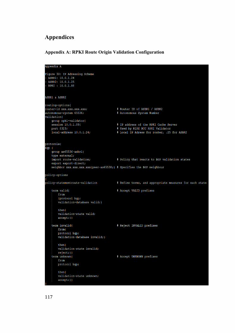
117
Appendices
Appendix A: RPKI Route Origin Validation Configuration
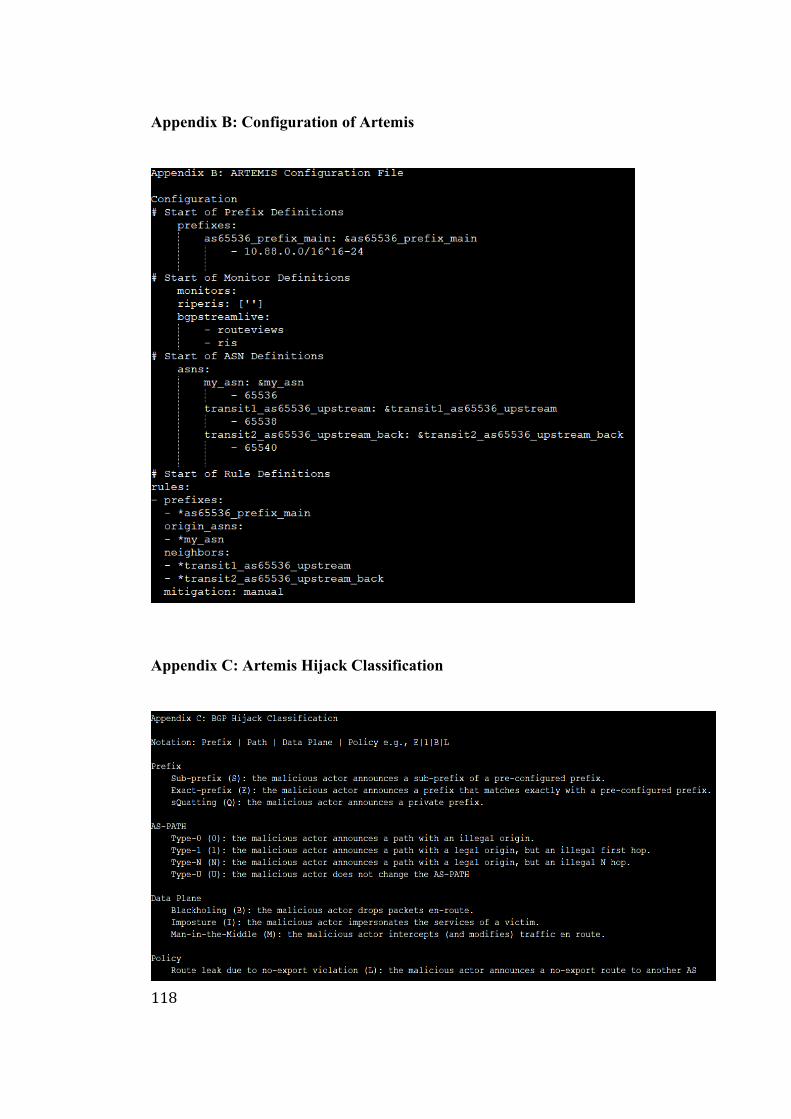
118
Appendix B: Configuration of Artemis
Appendix C: Artemis Hijack Classification
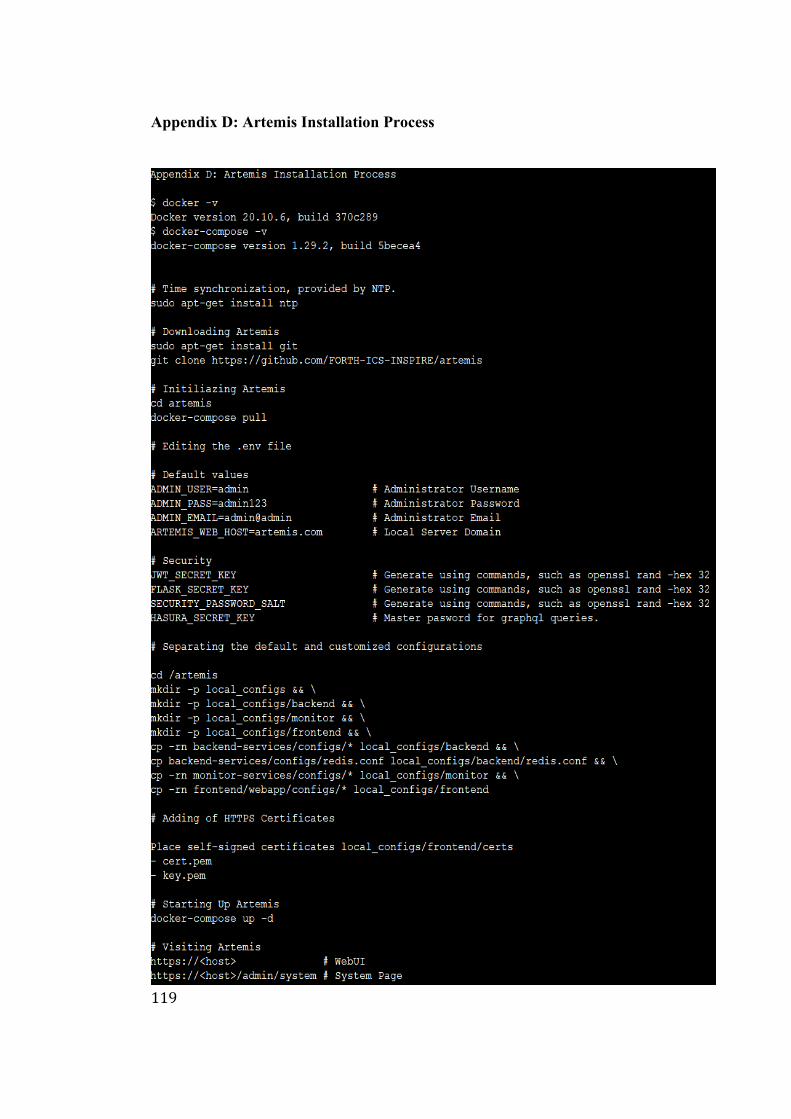
119
Appendix D: Artemis Installation Process

![CS 557 BGP Convergencemassey/Teaching/cs557/... · [BAS03] Improving BGP Convergence • Objective: – Improve convergence time after a legitimate route change. • Approach: –](https://img.pdfslide.us/doc/110x75/61180303e9a1557ed003301e/cs-557-bgp-masseyteachingcs557-bas03-improving-bgp-convergence-a-objective.jpg)