Embed Size (px)
Citation preview

Proceedings in Manufacturing Systems, Volume 11, Issue 2, 2016, 71‒76
ISSN 2067-9238
OPTIMIZATION OF AN INTAKE SYSTEM USING CFD NUMERICA L SIMULATION
Frantisek SEDLACEK 1,*, Michal SKOVAJSA2
1, 2) Eng., Faculty of Mechanical Engineering, University of West Bohemia, Pilsen, Czech Republic
Abstract: The paper deals with the use of CFD numerical simulations during the design and optimization of components, which are used for air distribution taking into account temperature. An intake manifold for a light racing vehicle has been chosen as a representative example. The aim of the research is to find a solution with the best possible distribution of air to the individual cylinders of the engine, whilst ensuring the quick response of the car engine. This type of analysis is very problematic because there is high speed compressible flow of air in the intake system, pressure drops and changes of temperatures. The optimization of the shape of the airbox is achieced in connection with CFD simulation (solver Siemens NX Advanced Flow) with the geometrical optimization of the generic model of the airbox. A 1D model of the engine was created to obtain the input data for CFD analysis. Values of pressures and temperatures for the individual cylinders of the engine in relation to time were subsequently generated from the 1D model. These values are used as input for the CFD analysis. The final analysis was performed as transient for several combustion cycles of the engine. Key words: numerical simulation, CFD, intake manifold
1. INTRODUCTION 1
The paper deals with the use of Computational Fluid Dynamics (CFD) numerical simulations during the design and optimization of components, which are used for air distribution. An intake manifold for a light racing vehicle has been chosen as a representative example. More precisely, a design was selected with optimization of the airbox for single seat race car of category Formula Student. The goal of this work is to find the most appropriate design of the airbox using CFD numerical analyses. The intake manifold (in slang also "airbox") is the component of an engine that supplies a mixture of air and fuel (or just air in a direct injection engine) to the cylinders of the engine. The design and optimization using CFD numerical simulation is very problematic for a Formula Student car, because this category of cars can use only a single throttle with an air intake restrictor with 20 mm diameter. For this reason, there is very high speed of the air and pressure drops in the airbox.
At the beginning it was necessary to determine the process of the design and optimization of the airbox. It is very problematic to obtain the necessary input parameters for CFD analysis, because it is not possible to use a stationary type numerical analysis. The 1D model of the intake and exhaust system of the engine was created for these reasons. The 1D model of the engine was done in Lotus Engine Simulation software. Furthermore, in that software will be found the most suitable basic parameters of the airbox (such as the
* Corresponding author: Univerzitni 8, Pilsen 306 14, Czech Republic, E-mail [email protected] (F. Sedlacek), [email protected] (M. Skovajsa)
lengths of the resonance pipes, total volume of the airbox, etc.).
Subsequently, the values of the air pressure in the outlets of the airbox will be generated based on this software. These values will be used as input parameters for CFD numerical simulation. The CFD numerical simulation will be combined with geometric optimization to ensure the best final shape of the airbox. The designed process can be seen in Fig. 1.
Fig. 1. Flowchart of the design and an optimization process.

72 F. Sedlacek and M. Skovajsa / Proceedings in Manufacturing Systems, Vol. 11, Iss. 2, 2016 / 71−76
2. 1D SIMULATION OF THE ENGINE
A Yamaha YZF-R6 motorbike engine with displacement 599.4 cc (year of manufacture 2013) was chosen. The 1D simulation of the engine was done in Lotus Engine Simulation software (hereafter referred to as LES). 2.1. Determination of the elementary properties of the
engine At first, it was necessary to obtain all the parameters
to create a 1D model. For this reason, we measured all the geometric parameters of the intake and exhaust manifold, combustion chamber, valves, etc. from a highly accurate 3D scan of the engine. In Table 1 several parameters are specified and in Fig. 2 the 3D scan of the Yamaha YZF-R6 engine is shown.
Table 1 The parameters of the engine
Engine Displacement 599cc Compression Ratio 13.1:1 Valves Per Cylinder 4 Bore x Stroke 67 x 42.5 mm Connecting Rod 90.5 mm/steel Claimed Engine Redline 16,000 rpm Valve Angle (Included) 11.5° Intake / 12.25° Combustion Chamber Volume 12.38 cc Valve Train Type DOHC, Link-plate Intake Valve Diameter 27.0 mm Exhaust Valve Diameter 23.0 mm Intake Valve Stem Diameter 4.5 mm Exhaust Valve Stem Diameter 4.5 mm Intake Valve Maximum Lift 8.5 mm Exhaust Valve Maximum Lift 7.7 mm
Intake Valve Timing Open BTDC 39° Close ABDC 65° Duration 284°
Exhaust Valve Timing Open BBDC 64° Close ATDC 24° Duration 268° Valve Timing Measuring Point Intake 0.15 mm, Exhaust Exhaust System Type 4-2-1
Fig. 2. 3D scan of the Yamaha YZF-R6 engine.
Fig. 3. 3D scan of the combustion chamber with valves of the Yamaha YZF-R6 engine.
Fig. 3 shows the 3D scan of the combustion chamber with intake and exhaust pipes and valves of the Yamaha YZF-R6 engine. 2.2. The 1D model of the engine
Subsequently, a complete 1D model engine was created in the LES, see Fig. 4. All obtained geometric parameters of the intake and exhaust manifold from the 3D scan of the engine were entered into the 1D model (such as variable diameters of the intake and exhaust pipes dependent on their length, angles in the pipe joints of the intake and exhaust manifold, materials with thermal properties, etc.). Furthermore, analytically determined initial values of the resonant pipes lengths and volume of the plenum of the airbox were entered (according to [1]). And finally, all other parameters of the engine (such as intake and exhaust valve timing, compression ratio, etc.) were defined.
Fig. 4. The 1D model of the engine with a modified intake and exhaust system (according to FSAE rules).

F. Sedlacek and M. Skovajsa / Proceedings in Manufacturing Systems, Vol. 11, Iss. 2, 2016 / 71−76 73
In LES, several simulations of the engine were done to find the most appropriate length of the resonance pipes for the whole operating speed range of the engine. More specifically, the length of the resonance pipes was searched for in the range 180‒500 mm and the total volume of the airbox was searched for in the range 4‒8 dm3.
The results show that long runners provide high torque at low rpm of the engine and short runners are advantageous at high engine speeds. In terms of the size of the plenum of the airbox, a small airbox volume provides better throttle response, but a large volume airbox allows high power of the engine.
Double length of runners (292 and 318 mm ‒ from intake valve seats) and an airbox with a volume of 6.15 dm3 were selected from individual variants.
The final distribution of the velocities, pressures and the mass flows of the air in the airbox are given in Chart 1‒Chart 3. The values are evaluated at the outlets of the pipes of the airbox for one operation cycle of the engine (rotation of the crankshaft 720 °) at 12 000 rpm, see Fig. 5.
Fig. 5. Measured points on the intake system.
Chart 1. The velocity of the air at the end of the intake system, at 12000 [rpm].
Chart 2. The pressure of the air at the end of the intake system, at 12000 [rpm].
Chart 3. The mass flow rate of the air at the end of the intake system, at 12000 [rpm].
3. DESIGN OF THE BASIC SHAPE OF THE
AIRBOX
Several types of the basic design of the airbox were created based on the parameters of the 1D simulation. Subsequently, the most suitable design was chosen – the inlet of the airbox is located in the longitudinal axis of the intake manifold and runners are located in line in the transverse axis, see Fig. 6. This design provides good distribution of air into engine.
This model was created as a generic to enable subsequent application of the geometric optimization.
74 F. Sedlacek and M. Skovajsa / Proceedings in Manufacturing Systems, Vol. 11, Iss. 2, 2016 / 71−76
Fig. 6. The basic shape of the intake manifold.
4. THE CFD ANALYSIS OF THE AIRBOX
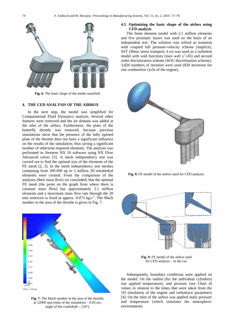
In the next step, the model was simplified for Computational Fluid Dynamics analysis. Several other features were removed and the air domain was added at the inlet of the airbox. Furthermore, the plate of the butterfly throttle was removed, because previous simulations show that the presence of the fully opened plate of the throttle does not have a significant influence on the results of the simulation; thus saving a significant number of otherwise required elements. The analysis was performed in Siemens NX 10 software using NX Flow Advanced solver [5]. A mesh independency test was carried out to find the optimal size of the elements of the FE mesh [2, 3]. In the mesh independency test meshes containing from 300 000 up to 5 million 3D tetrahedral elements were created. From the comparison of the analyses (their mass flow) we concluded; that the optimal FE mesh (the point on the graph from where there is constant mass flow) has approximately 2.1 million elements and a maximum mass flow rate through the 20 mm restrictor is fixed at approx. 0.073 kg.s-1. The Mach number in the area of the throttle is given in Fig. 7.
Fig. 7. The Mach number in the area of the throttle, at 12000 rpm (time of the simulation ‒ 0.03 sec,
angle of the crankshaft – 216°).
4.1. Optimizing the basic shape of the airbox using CFD analysis
The finite element model with 2.1 million elements and five prismatic layers was used on the basis of an independent test. The solution was solved as transient with coupled full pressure-velocity scheme (implicit), SST (Shear stress transport; k-ω) was used as a turbulent model with wall functions (max wall y+
≈45) and second order discretization scheme (SOU discretization scheme). 3,820 numbers of iteration were used (820 iterations for one combustion cycle of the engine).
Fig. 8. FE model of the airbox used for CFD analysis.
Fig. 9. FE model of the airbox used for CFD analysis ‒ in the cut.
Subsequently, boundary conditions were applied on the model. On the outlets (for the individual cylinders) one applied temperatures, and pressure (see Chart 4) values in relation to the times that were taken from the 1D simulation of the engine and turbulence parameters [4]. On the inlet of the airbox was applied static pressure and temperature (which simulates the atmospheric environment).

F. Sedlacek and M. Skovajsa / Proceedings in Manufacturing Systems, Vol. 11, Iss. 2, 2016 / 71−76 75
Chart 4. The pressure distribution for the individual cylinders of the engine; at 12000 rpm (red – 1. Cylinder).
Fig. 10. Geometric parameter of the shape of the airbox.
The geometric optimization with CFD numerical
simulation was connected. The maximum mass flow through the airbox was chosen as the objective function of the geometric optimization and the total volume of the airbox (6.15 dm3) was selected as the constraint of the optimization. The individual input parameters for the optimization cycle are given in Fig. 10.
The parameters of the final variant are shown in Fig. 10. The final variant provides uniform filling of all cylinders of the engine; maximum difference is 2.2%. The results of the mean mass flow for each cylinder are around 0.051 kg.s‒1. The results of the pressures and velocity of the air in the airbox for several time steps are shown in Fig. 11‒13.
Table 2 The parameters of the final design of the airbox
Parameter [units] Value alpha [deg] 7 beta [deg] 2
gamma [deg] 112 h1 [mm] 150 h2 [mm] 256 r1 [mm] 19
Fig. 11. Velocity of the air in the airbox [m/s] (at 12000 rpm of the engine; time 0.03 sec, angle of the crankshaft 0°).
Fig. 12. Velocity of the air in the airbox [m/s] (at 12000 rpm of the engine; time 0.03125 sec, angle of the crankshaft 90°).
Fig. 13. Velocity of the air in the airbox [m/s] (at 12000 rpm of the engine; time 0.0325 sec, angle of the crankshaft 180°).

76 F. Sedlacek and M. Skovajsa / Proceedings in Manufacturing Systems, Vol. 11, Iss. 2, 2016 / 71−76
Fig. 14. Pressure in +ve side [bars] (at 12000 rpm of the engine; time 0.03 sec, angle of the crankshaft 0°).
Fig. 15. Pressure in +ve side [bars] (at 12000 rpm of the engine; time 0.033sec, angle of the crankshaft 216°).
5. CONCLUSIONS
This paper dealt with using CFD numerical simulation for the design and the optimization of an airbox for a Formula Student one-seat racing car. The goal was to find the shape of the airbox, which ensures a good distribution of the air in to the individual cylinders of the engine, and maximize the volume flow and the quick engine response of the engine. The 1D model of the engine including the intake and exhaust system was created to find the input parameters for the CFD numerical simulation. Furthermore, the basic geometric parameters of the intake manifold (more precisely; the
Table 3
Mean mass flow during suction phase [kg.s−1], at 12000 rpm
Cylinder 1 Cylinder 2 Cylinder 3 Cylinder 4
0.0521 0.0512 0.0517 0.0514
Fig. 16. The final design of the assembly
of the intake manifold. length of the resonant pipe and the volume of the plenum of the airbox) were determined by using this 1D analysis. Subsequently, the CFD numerical simulation in connection with the geometric optimization was done to find the suitable basic shape of the airbox. The final variant provides uniform filling of all cylinders of the engine; maximum difference is only approx. 2.2%. The results of the mean mass flow for each cylinder are around 0.051 kg.s−1 (see Table 3).
This design of the airbox will be built and experimentally tested by using several pressure and temperature sensors to verify the numerical simulation (see Fig. 16).
ACKNOWLEDGEMENTS: This paper is based on
work sponsored by project SGS2016-012 (The complex support of designing of technical equipment III.).
REFERENCES
[1] M. Trzesniowski, Rennwagentechnik: Grundlagen, Konstruktion, Komponenten, Systeme. Wiesbaden, Vieweg Teubner, 2008.
[2] Löhner, Rainald. Applied Computational Fluid Dynamics Techniques: An Introduction Based on Finite Element Methods, Chichester: Wiley, 2001.
[3] Tu, Jiyuan, Guan Heng. Yeoh, and Chaoqun Liu. Computational Fluid Dynamics: A Practical Approach. Amsterdam: Butterworth-Heinemann, 2008.
[4] Çengel, Yunus A., and John M. Cimbala. Fluid Mechanics: Fundamentals and Applications, Boston: McGraw-HillHigher Education, 2006.
[5] Goncharov, Pavel, Engineering Analysis with NX Advanced Simulation, Raleigh: Lulu, 2014. Print.