Embed Size (px)
Citation preview
AB-2029 Rev. 05.09
Page | 1
Introduction
The role of light armored vehicles (LAVs) is ever increasing as improvised explosive devices (IEDs) become more common in battlefield areas. LAVs are used to transport troops and supplies in a safe and efficient manner. With increasing threats from IEDs (as well as landmines and other explosive devices) comes the need for better vehicle armor to protect troops and equipment. Design of armor solutions that provide adequate protection without sacrificing functionality or adding too much mass is a serious challenge.
Each physical test of an LAV’s resistance to blast loading typically destroys the armor and/or the vehicle, making repeated tests both expensive and time consuming. Thus, accurate CAE simulations of explosions and the associated response of the armored vehicle are an important part of the design process for LAVs. Further, with access to accurate simulations, automated mathematical-based design optimization can be utilized to design stronger, lighter, more efficient and lower cost armor for LAVs.
Here, we demonstrate how design optimization can be utilized in designing an armored plate for the undercarriage of an LAV. A validated loading model for simulating blast mine effects was utilized in this study. LS-DYNA was used to simulate the dynamic blast response, and HEEDS Professional was used to perform the automated optimization in order to design a sufficiently light armored plate with an optimal material and thickness that minimized intrusion into the vehicle.
Blast Simulation
The validated loading model described by Williams, et al. [1] for simulating blast mine effects on armored vehicles was employed in this study. The explosion was represented using the CONWEP blast equations (Kingery and Bulmash [2]) as implemented in LS-DYNA through the *LOAD_BLAST keyword [3]. While Arbitrary-Lagrangian-Eulerian (ALE) techniques for simulating blast are known to be
accurate, the CONWEP blast function is less computationally expensive. This function has been shown to be accurate for free air detonation of spherical charges and surface detonations of hemispherical charges, through its calculation of reflected pressures and their application to surfaces, taking into account the angle of incidence of the blast wave [4].
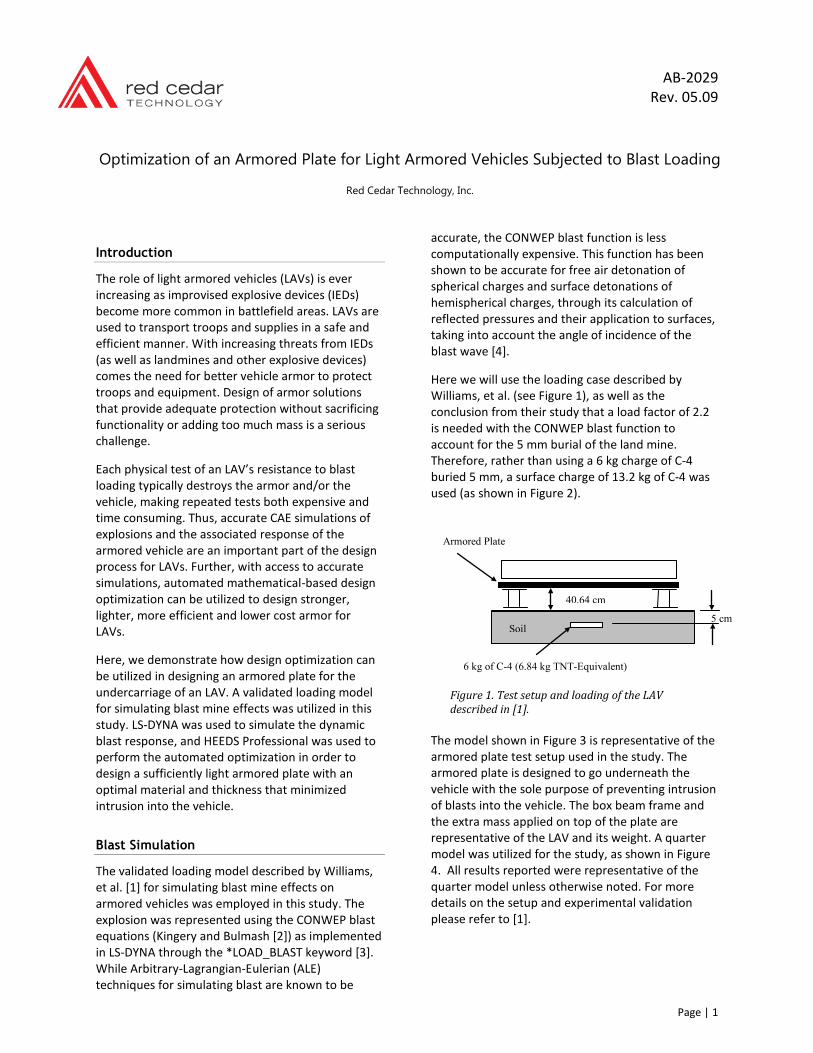
Here we will use the loading case described by Williams, et al. (see Figure 1), as well as the conclusion from their study that a load factor of 2.2 is needed with the CONWEP blast function to account for the 5 mm burial of the land mine. Therefore, rather than using a 6 kg charge of C-4 buried 5 mm, a surface charge of 13.2 kg of C-4 was used (as shown in Figure 2).
Figure 1. Test setup and loading of the LAV described in [1].
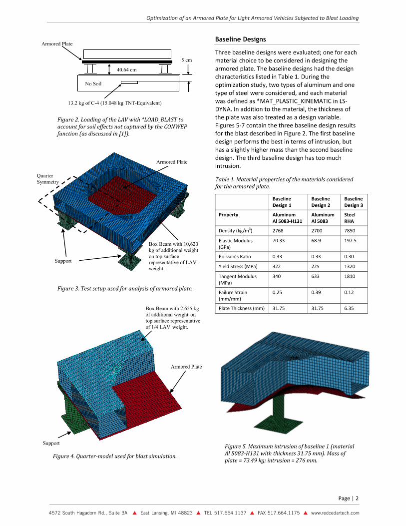
The model shown in Figure 3 is representative of the armored plate test setup used in the study. The armored plate is designed to go underneath the vehicle with the sole purpose of preventing intrusion of blasts into the vehicle. The box beam frame and the extra mass applied on top of the plate are representative of the LAV and its weight. A quarter model was utilized for the study, as shown in Figure 4. All results reported were representative of the quarter model unless otherwise noted. For more details on the setup and experimental validation please refer to [1].
Optimization of an Armored Plate for Light Armored Vehicles Subjected to Blast Loading
Red Cedar Technology, Inc.
5 cm Soil
6 kg of C-4 (6.84 kg TNT-Equivalent)
Armored Plate
40.64 cm
Optimization of an Armored Plate for Light Armored Vehicles Subjected to Blast Loading
Page | 2
Figure 2. Loading of the LAV with *LOAD_BLAST to account for soil effects not captured by the CONWEP function (as discussed in [1]).
Figure 3. Test setup used for analysis of armored plate.
Figure 4. Quarter-model used for blast simulation.
Baseline Designs
Three baseline designs were evaluated; one for each material choice to be considered in designing the armored plate. The baseline designs had the design characteristics listed in Table 1. During the optimization study, two types of aluminum and one type of steel were considered, and each material was defined as *MAT_PLASTIC_KINEMATIC in LS-DYNA. In addition to the material, the thickness of the plate was also treated as a design variable. Figures 5-7 contain the three baseline design results for the blast described in Figure 2. The first baseline design performs the best in terms of intrusion, but has a slightly higher mass than the second baseline design. The third baseline design has too much intrusion.
Table 1. Material properties of the materials considered for the armored plate.
Baseline Design 1
Baseline Design 2
Baseline Design 3
Property Aluminum Al 5083-H131
Aluminum Al 5083
Steel RHA
Density (kg/m3) 2768 2700 7850
Elastic Modulus (GPa)
70.33 68.9 197.5
Poisson’s Ratio 0.33 0.33 0.30
Yield Stress (MPa) 322 225 1320
Tangent Modulus (MPa)
340 633 1810
Failure Strain (mm/mm)
0.25 0.39 0.12
Plate Thickness (mm) 31.75 31.75 6.35
Figure 5. Maximum intrusion of baseline 1 (material Al 5083-H131 with thickness 31.75 mm). Mass of plate = 73.49 kg; intrusion = 276 mm.
Armored Plate
No Soil
40.64 cm
5 cm
13.2 kg of C-4 (15.048 kg TNT-Equivalent)
Armored Plate
Box Beam with 10,620 kg of additional weight on top surface representative of LAV weight.
Support
Quarter Symmetry
Armored Plate
Box Beam with 2,655 kg of additional weight on top surface representative of 1/4 LAV weight.
Support
Optimization of an Armored Plate for Light Armored Vehicles Subjected to Blast Loading
Page | 3
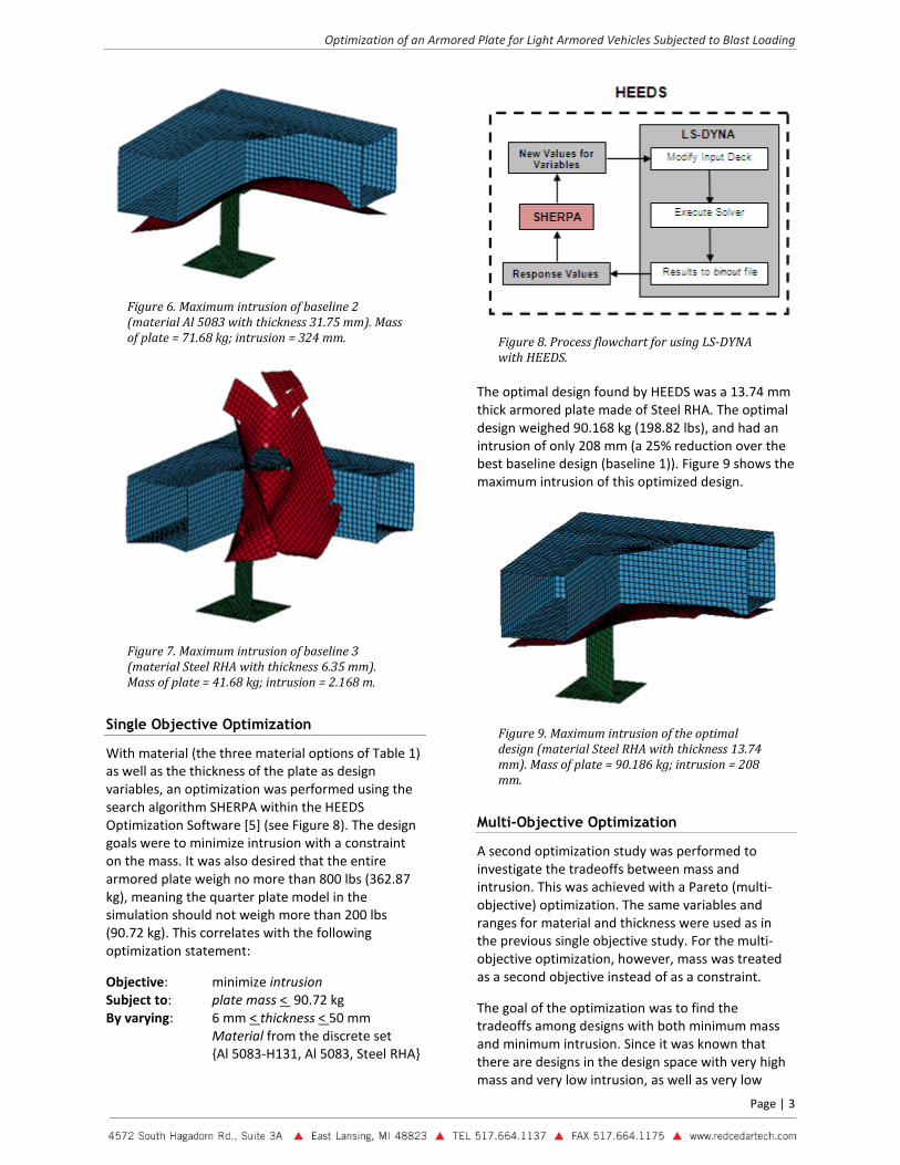
Figure 6. Maximum intrusion of baseline 2 (material Al 5083 with thickness 31.75 mm). Mass of plate = 71.68 kg; intrusion = 324 mm.
Figure 7. Maximum intrusion of baseline 3 (material Steel RHA with thickness 6.35 mm). Mass of plate = 41.68 kg; intrusion = 2.168 m.
Single Objective Optimization
With material (the three material options of Table 1) as well as the thickness of the plate as design variables, an optimization was performed using the search algorithm SHERPA within the HEEDS Optimization Software [5] (see Figure 8). The design goals were to minimize intrusion with a constraint on the mass. It was also desired that the entire armored plate weigh no more than 800 lbs (362.87 kg), meaning the quarter plate model in the simulation should not weigh more than 200 lbs (90.72 kg). This correlates with the following optimization statement:
Objective: minimize intrusion Subject to: plate mass < 90.72 kg By varying: 6 mm < thickness <
Figure 8. Process flowchart for using LS-DYNA with HEEDS.
The optimal design found by HEEDS was a 13.74 mm thick armored plate made of Steel RHA. The optimal design weighed 90.168 kg (198.82 lbs), and had an intrusion of only 208 mm (a 25% reduction over the best baseline design (baseline 1)). Figure 9 shows the maximum intrusion of this optimized design.
50 mm Material from the discrete set {Al 5083-H131, Al 5083, Steel RHA}
Figure 9. Maximum intrusion of the optimal design (material Steel RHA with thickness 13.74 mm). Mass of plate = 90.186 kg; intrusion = 208 mm.
Multi-Objective Optimization
A second optimization study was performed to investigate the tradeoffs between mass and intrusion. This was achieved with a Pareto (multi-objective) optimization. The same variables and ranges for material and thickness were used as in the previous single objective study. For the multi-objective optimization, however, mass was treated as a second objective instead of as a constraint.
The goal of the optimization was to find the tradeoffs among designs with both minimum mass and minimum intrusion. Since it was known that there are designs in the design space with very high mass and very low intrusion, as well as very low
Optimization of an Armored Plate for Light Armored Vehicles Subjected to Blast Loading
Page | 4
mass and very high intrusion, constraints were placed on these two responses to limit the exploration to a reasonable range. This resulted in the following optimization statement:
Objectives: minimize intrusion & minimize plate mass
Subject to: plate mass < 150 kg intrusion < 500 mm
By varying: 6 mm < thickness <
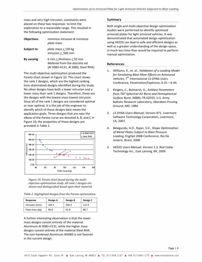
Figure 10. Pareto chart found during the multi-objective optimization study. All rank 1 designs are shown and distinguished based upon their material.
Table 2. Highlighted designs from the Pareto optimization.
50 mm Material from the discrete set {Al 5083-H131, Al 5083, Steel RHA}
The multi-objective optimization produced the Pareto chart shown in Figure 10. This chart shows the rank 1 designs, which are the highest ranking (non-dominated) designs identified during the study. No other designs have both a lower intrusion and a lower mass than rank 1 designs. Therefore, these are the designs with the lowest mass-lowest intrusion. Since all of the rank 1 designs are considered optimal or near optimal, it is the job of the engineer to identify which of these designs best meets the application goals. Three designs that are near the elbow of the Pareto curve are denoted A, B, and C in Figure 10; the properties of these designs are provided in Table 2.
Response Design A Design B Design C
Intrusion (mm) 192.5 204.4 212.0
Plate mass (kg) 96.8 91.8 88.7
A further interesting observation is that the lower mass designs consist entirely of the material Aluminum Al 5083-H131, while the higher mass designs consist entirely of the material Steel RHA. The non-hardened Aluminum Al5083 is not favored in the current design.
Summary
Both single and multi-objective design optimization studies were performed to identify optimized armored plates for light armored vehicles. It was demonstrated that automated design optimization using HEEDS can lead to safe and efficient designs as well as a greater understanding of the design space, in much less time than would be required to perform manual optimization.
References
1. Williams, K., et. al., Validation of a Loading Model for Simulating Blast Mine Effects on Armoured Vehicles, 7th International LS-DYNA Users Conference, Penetration/Explosive, 6-35 – 6-44.
2. Kingery, C., Bulmarsh, G., Airblast Parameters from TNT Spherical Air Burst and Hemispherical Surface Burst, ARBRL-TR-02555, U.S. Army Ballistic Research Laboratory, Aberdeen Proving Ground, MD, 1984.
3. LS-DYNA Users Manual, Version 971, Livermore Software Technology Corporation, Livermore, CA, 2007.
4. Belegundu, A.D., Rajan, S.D., Shape Optimization of Metal Plates Subject to Blast Pressure Loading, EngOpt 2008 Conference, Rio De Janeiro, Brazil, 2008.
5. HEEDS Users Manual, Version 5.3, Red Cedar Technology Inc., East Lansing, MI, 2009.