Embed Size (px)
Citation preview
International Journal of Science and Research (IJSR) ISSN (Online): 2319-7064
Index Copernicus Value (2013): 6.14 | Impact Factor (2013): 4.438
Volume 4 Issue 6, June 2015
www.ijsr.net Licensed Under Creative Commons Attribution CC BY
Optimization and Performance Evaluation of
Poultry Feed Mixer
Ugwu Kenneth Chikwado
Department Of Agricultural And Bioresources Engineering, Enugu State University Of Science And Technology, Enugu
Abstract: A motorized vertical poultry feed mixer was optimized, fabricated and its performance was evaluated. An appropriate mixing
ratio or quality of a good poultry feeds are based on the correct application of the properties of granular materials. These properties,
which include maximum particle size, moisture content, bulk density, angle of repose, fineness modulus of granular material, coefficient
of friction with their standard parameters are given as 6.5 mm, 9.3 %, 548.6 3/ mKg , 35º, 2.4 and 0.5 respectively. The optimized
fabricated mixer compounded feed at 7.44 mm, 9.6 %, 571.63/ mKg , 39º, 2.6 and 0.6 respectively. The coefficient of variation of
standard poultry feed mixing parameter to the fabricated mixer was 17.2 %. The fabricated machine was evaluated using 400, 480 and
560 rpm speed of mixing auger to produce 250 Kg of feed and its mixing efficiency were given as 74 %, 83.6 % and 78.2 % respectively.
A homogeneous feed was obtained at 105 minutes. The feeds produced were used to breed some day old chicks to maturity and
proximate analysis of feed nutrients was carried out on each feed compounded and it was satisfactory. Starter’s mash, grower’s mash,
finisher’s mash and layer’s mash were compounded using the fabricated machine and its best performance efficiency was at 480 rpm
which is 83.6 %. It was found that the cost of producing a bag of feed was reduced by 40 % as compared to the market price at the time
the experiment was performed. The mixer produces good quality or homogeneous feed by correct application of the properties of
granular materials.
Keywords: optimization, performance, evaluation, poultry feed, mixer
1. Introduction
As mill became multistoried structures, gravity spouting was
used to direct the meal and grain flow from the top of the
elevator legs. However, gravity spouting could neither reach
the locations desired nor handle the various textures of
grains selected by mill customers to meet their own
individual needs. Horizontal devices were merely shaft with
short pegs fastened in a spiral pattern which advanced the
grain when the shaft rotated, all housed in long wooden
boxes. With an invention of electric motor, sweeping
changes in mill design took place. A specialized type of
conveyor was developed called a feeder. The construction
was similar to the material handling conveyor, except it was
shorter and by a motor and a speed reduction device called a
gear box. This allowed for the achievement of variable
speeds, which afforded mill operators added flexibility of
operation (Culpin, 2000).
As the list of available ingredients increased, the mill
operator was forced to reserve a bin or box for each
ingredient. This process was accelerated as scientific
research began to show the advantages of feeding balanced
diets. The feeders were designed to empty into a large, slow-
moving, collecting conveyor, which usually included a
method to impede or separate part of the flow in an effort to
improve blending. The storage of whole and ground grains
has changed little since the construction of the first mill bins.
This was the key component of the first so-called feeder line
for the production of formula feeds on the American
continents. Demand for higher production output led to the
development of the feeder line plants. It has become obvious
that acceptable weight control was difficult to achieve due to
the variable densities of the individual ingredients that were
being routinely used (George, 2009).
Each feeder was located under a single ingredient or premix
bin which was put through the hopper and spouted to
provide constant, uniform flows regardless of the rate
demanded by the feeder. The inconsistencies of the
volumetric feeder, resulting from variable ingredients, led to
the development of the gravimetric feeder. This device
allowed for continuous weight checks and provided
automatic adjustment of the gate control mechanism. With
the advent of drug and antibiotic use, it became obvious that
the feeder line was incapable of accurately handling and
mixing products with an inclusion rate of less than 1% of
mix. This led to the premixing of these micro ingredients to
a level above 1% with a diluents or carrier. This was usually
accomplished at alternative site by more sophisticated
equipment than described above (George, 2009).
In the early days on small family farm, the mixing of home
grown grains with supplements purchased from the local
miller began with a smooth floor, shovel and knowledge of
quartering. Local village and commercial operators were
more refined and had the advantage of both grinding and
screening facilities to increase the efficacy of the formulas
that were being prepared for animal feeds. In time, operators
duplicated the action of the shovel by fashioning crude
plows or paddles fastened to slowly rotating horizontal
shafts contained in a wooden box with curved bottom
(Culpin, 2000).
The mixing of feedstuffs to form a ration is a regular need
on the large stock farms. There have been few official tests
of the evenness of mix of the various types of machine.
Table below shows the nominal capacities, range of gross
volumes and power requirement for typical bottom fed
mixers of conical shape. Such mixers usually operate at a
speed of 400 – 600 rpm and require more power for a given
capacity than top feed machines, which usually operate on
Paper ID: SUB155658 1303
International Journal of Science and Research (IJSR) ISSN (Online): 2319-7064
Index Copernicus Value (2013): 6.14 | Impact Factor (2013): 4.438
Volume 4 Issue 6, June 2015
www.ijsr.net Licensed Under Creative Commons Attribution CC BY
only 150 – 200 rpm. Capacities and power requirement of
typical vertical auger mixers are tabulated below.
Table 1: Different Density of Material and Power Required Batch size
(tones)
Ration
(3m )
High density
ration (3m )
Power
requirement
(hp)
Power
requirement
(kw)
0.5 1.6 1.2 3 – 4 2.2 – 3.0
1.0 3.2 2.5 4 – 5 3.0 – 3.7
1.5 4.8 3.6 5 – 7.5 3.7 – 5.6
2.0 6.4 5.0 7.5 - 10 5.6 – 7.5
( Culpin, 2000).
2. Materials and Method
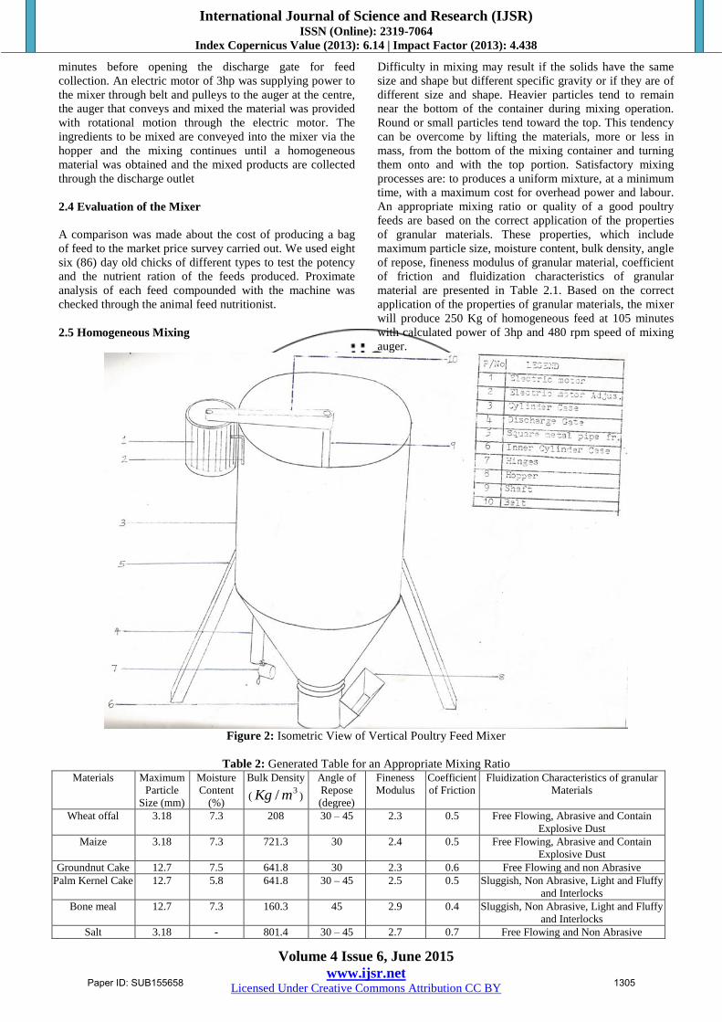
2.1 Description of the Mixer
A motorized vertical poultry feed mixer,(fig. 2) efficient and
economically viable was optimized and fabricated with
readily available and cheap materials (suitable engineering
materials that could give optimum performance in service).
Materials for fabricating the machine and for feed
compoundments were chosen on the basis of their
availability, suitability, economic consideration, viability in
service etc. The major components of the machine are as
follows: Cylinder case (3), Inner casing covering the auger
(6), Discharge gate (4), Hopper (8), Shaft (9), tripod stand (5)
and electric motor (1).
2.2 Methods and Optimization of poultry feed mixer
The shaft is a cylindrical solid rod for transmitting motion
through a set of load carried on it. The shaft uses for the
mixing is loaded by a press screw auger, bearings, pulley,
and belt tension. All these forces act on the shaft. The design
is based on fluctuating torque, bending moment and shearing
force. These called for knowing the combined shock and
fatigue on the shaft. To determine the shaft diameter, we
adopt the formula;
d3 =
Where;
d = diameter of shaft (mm)
Kb = combined shock and fatigue factor for bending
moment.
Kt = combined shock and fatigue factor for torsional
moment.
Mb = Resultant bending moment (Nm)
Mt = Resultant torsional moment (Nm)
δsy = Allowable shear stress (MN/m2)
π = constant, 3.142
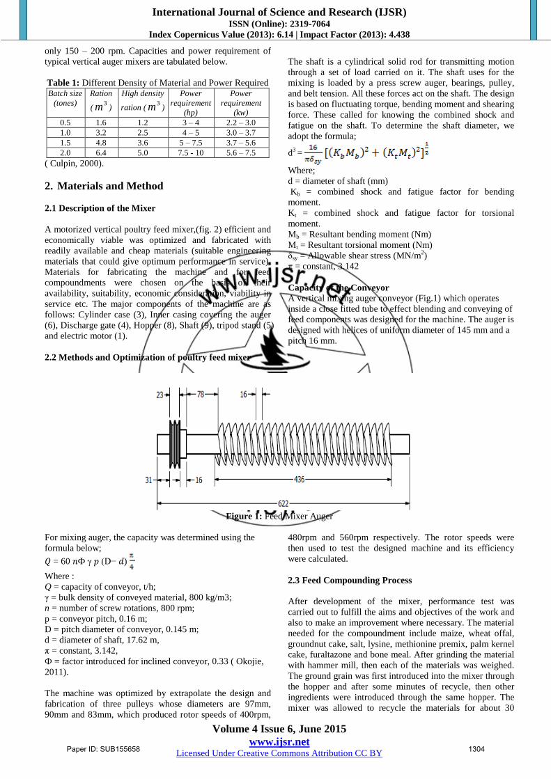
Capacity of the Conveyor
A vertical mixing auger conveyor (Fig.1) which operates
inside a close fitted tube to effect blending and conveying of
feed components was designed for the machine. The auger is
designed with helices of uniform diameter of 145 mm and a
pitch 16 mm.
Figure 1: Feed Mixer Auger
For mixing auger, the capacity was determined using the
formula below;
𝑄 = 60 𝑛Ф γ 𝑝 (D− 𝑑)
Where :
Q = capacity of conveyor, t/h;
γ = bulk density of conveyed material, 800 kg/m3;
n = number of screw rotations, 800 rpm;
p = conveyor pitch, 0.16 m;
D = pitch diameter of conveyor, 0.145 m;
d = diameter of shaft, 17.62 m,
π = constant, 3.142,
Ф = factor introduced for inclined conveyor, 0.33 ( Okojie,
2011).
The machine was optimized by extrapolate the design and
fabrication of three pulleys whose diameters are 97mm,
90mm and 83mm, which produced rotor speeds of 400rpm,
480rpm and 560rpm respectively. The rotor speeds were
then used to test the designed machine and its efficiency
were calculated.
2.3 Feed Compounding Process
After development of the mixer, performance test was
carried out to fulfill the aims and objectives of the work and
also to make an improvement where necessary. The material
needed for the compoundment include maize, wheat offal,
groundnut cake, salt, lysine, methionine premix, palm kernel
cake, furaltazone and bone meal. After grinding the material
with hammer mill, then each of the materials was weighed.
The ground grain was first introduced into the mixer through
the hopper and after some minutes of recycle, then other
ingredients were introduced through the same hopper. The
mixer was allowed to recycle the materials for about 30
Paper ID: SUB155658 1304
International Journal of Science and Research (IJSR) ISSN (Online): 2319-7064
Index Copernicus Value (2013): 6.14 | Impact Factor (2013): 4.438
Volume 4 Issue 6, June 2015
www.ijsr.net Licensed Under Creative Commons Attribution CC BY
minutes before opening the discharge gate for feed
collection. An electric motor of 3hp was supplying power to
the mixer through belt and pulleys to the auger at the centre,
the auger that conveys and mixed the material was provided
with rotational motion through the electric motor. The
ingredients to be mixed are conveyed into the mixer via the
hopper and the mixing continues until a homogeneous
material was obtained and the mixed products are collected
through the discharge outlet
2.4 Evaluation of the Mixer
A comparison was made about the cost of producing a bag
of feed to the market price survey carried out. We used eight
six (86) day old chicks of different types to test the potency
and the nutrient ration of the feeds produced. Proximate
analysis of each feed compounded with the machine was
checked through the animal feed nutritionist.
2.5 Homogeneous Mixing
Difficulty in mixing may result if the solids have the same
size and shape but different specific gravity or if they are of
different size and shape. Heavier particles tend to remain
near the bottom of the container during mixing operation.
Round or small particles tend toward the top. This tendency
can be overcome by lifting the materials, more or less in
mass, from the bottom of the mixing container and turning
them onto and with the top portion. Satisfactory mixing
processes are: to produces a uniform mixture, at a minimum
time, with a maximum cost for overhead power and labour.
An appropriate mixing ratio or quality of a good poultry
feeds are based on the correct application of the properties
of granular materials. These properties, which include
maximum particle size, moisture content, bulk density, angle
of repose, fineness modulus of granular material, coefficient
of friction and fluidization characteristics of granular
material are presented in Table 2.1. Based on the correct
application of the properties of granular materials, the mixer
will produce 250 Kg of homogeneous feed at 105 minutes
with calculated power of 3hp and 480 rpm speed of mixing
auger.
Figure 2: Isometric View of Vertical Poultry Feed Mixer
Table 2: Generated Table for an Appropriate Mixing Ratio Materials Maximum
Particle
Size (mm)
Moisture
Content
(%)
Bulk Density
(3/ mKg )
Angle of
Repose
(degree)
Fineness
Modulus
Coefficient
of Friction
Fluidization Characteristics of granular
Materials
Wheat offal 3.18 7.3 208 30 – 45 2.3 0.5 Free Flowing, Abrasive and Contain
Explosive Dust
Maize 3.18 7.3 721.3 30 2.4 0.5 Free Flowing, Abrasive and Contain
Explosive Dust
Groundnut Cake 12.7 7.5 641.8 30 2.3 0.6 Free Flowing and non Abrasive
Palm Kernel Cake 12.7 5.8 641.8 30 – 45 2.5 0.5 Sluggish, Non Abrasive, Light and Fluffy
and Interlocks
Bone meal 12.7 7.3 160.3 45 2.9 0.4 Sluggish, Non Abrasive, Light and Fluffy
and Interlocks
Salt 3.18 - 801.4 30 – 45 2.7 0.7 Free Flowing and Non Abrasive
Paper ID: SUB155658 1305
International Journal of Science and Research (IJSR) ISSN (Online): 2319-7064
Index Copernicus Value (2013): 6.14 | Impact Factor (2013): 4.438
Volume 4 Issue 6, June 2015
www.ijsr.net Licensed Under Creative Commons Attribution CC BY
Soyabean 3.18 7.1 801.4 30 2.4 0.5 Free Flowing, Abrasive and Contain
Explosive Dust
Corn Bran 3.18 6.70 448.8 30 2.4 0.5 Free Flowing, Abrasive and Contain
Explosive Dust
Sorghum 3.18 7.1 512.9 30 - 45 2.1 0.6 Free Flowing, and Abrasive
(Mohsenin, 1986)
3. Results and Discussion
Table 2 presents the properties of granular material for the
compoundment of good quality or homogeneous feeds, if it
is correctly applied and Table 3 presents the properties of
granular materials used for the compoundment of feed by
the fabricated mixer.
Table 4 shows the cost of producing 250 Kg of starter’s
mash. The unit prices of the materials are stated. The market
price of 250 Kg of starter’ mash was 12,000 as against
7807.50.
Table 5 to 7 show the compoundment of grower’s, finisher’s
and layer’s mash and their prices per 250 Kg. The market
prices of the feeds are 8600, 13,500 and 11,000 as against
5,388, 8,364.5 and 6,867.50 production cost.
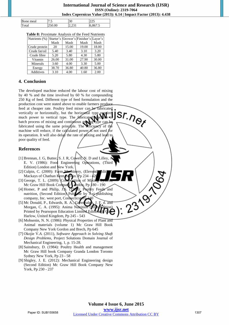
Table 8 presents the proximate analysis of feed nutrients.
Proximate analysis of feeds is the standard practical feed
formula for poultry. It was found out that the laboratory
determinations of the proximate analysis of produced feeds
are in line with the standard. It was from the proximate
analysis that each feed ration was compounded.
The compounded feeds were used as ration for 25 broilers,
35 cockerel and 26 layers day old chicks and they grew to
maturity. This is to say that the compounded feeds are
satisfactory. It could be deduced that the rate of mixing of
the developed machine was efficient compared to the
traditional method of mixing. The total time used for the
mixing of 250 Kg of feed was 105 minutes (4
31 hours) and
it was used to calculate the amount of feed to be produced
within a day, a week and a month with the developed
machine. It could be deduced that the rate of mixing of the
developed machine was efficient compared to the traditional
method of mixing.
Table 3: Properties of granular materials used for the fabricated mixer Materials Maximum Particle
Size (mm)
Moisture
Content (%)
Bulk Density
(3/ mKg )
Angle of Repose
(degree)
Fineness
Modulus
Coefficient of
Friction
Wheat offal 3.2 7.6 209 45 2.5 0.5
Maize 3.6 8.0 723 38 2.4 0.6
Groundnut Cake 12.9 7.5 648 33 2.4 0.6
Palm Kernel Cake 12.8 6.0 648 44 2.6 0.5
Bone meal 12.9 7.3 163 46 3.0 0.5
Salt 3.1 - 805 43 2.7 0.7
Soyabean 3.6 7.4 805 27 2.5 0.6
Table 4: 250 Kg of Starter’s Mash Compoundment Materials Quantity(Kg) Unit Price (#) Total Price(#)
Wheat offal 65 15 975
Maize 87 28.02 2438
Soya bean meal 67 56 3752
Palm kernel cake 30 7 210
Methionine 0.25 800 200
Salt 1.25 26 32.50
Lysine 0.25 800 200
Total 250.75 1732.02 7,807.50
Table 5: 250 Kg of Grower’s Mash Compoundment Materials Quantity (Kg) Unit Price(#) Total Price(#)
Wheat offal 53.6 15 804
Maize 53.6 28 1500.4
Groundnut cake 42.0 30 1260
Salt 1.35 26 35.1
Palm kernel cake 91.7 7 641.9
Bone meal 6.54 30 196.2
Lysine 0.25 800 200
Premix 1.25 440 550
Methionine 0.25 800 200
Total 250.54 2,176 5,388.00
Table 6: 250 Kg of Finisher’s Mash Compoundment Materials Quantity(Kg) Unit Price(#) Total Price(#)
Maize 112.5 28 3150
Wheat offal 40 15 600
Soya bean meal 60 56 3360
Bone meal 10 30 300
Palm kernel cake 25 7 175
Lysine 0.295 800 236
Salt 1.25 26 32.5
Methionine 0.295 800 236
Premix 0.625 440 275
Total 250.00 2,202 8,364.5
Table 7: 250 Kg of Layer’s Mash Compoundment Materials Quantity (Kg) Unit Price(#) Total Price(#)
Wheat offal 47.5 15 712.5
Soya bean meal 50 56 2800
Corn bran 87.5 20 1750
Groundnut cake 12.5 30 375
Lime stone 12.5 7 875
Methionine 0.25 800 200
Lysine 0.25 800 200
Salt 1.25 26 32.5
Premix 0.625 440 275
Palm kernel cake 30 7 210
Paper ID: SUB155658 1306
International Journal of Science and Research (IJSR) ISSN (Online): 2319-7064
Index Copernicus Value (2013): 6.14 | Impact Factor (2013): 4.438
Volume 4 Issue 6, June 2015
www.ijsr.net Licensed Under Creative Commons Attribution CC BY
Bone meal 7.5 30 225
Total 250.00 2,231 6,867.5
Table 8: Proximate Analysis of the Feed Nutrients
Nutrients (%) Starter’s
Mash
Grower’s
Mash
Finisher’s
Mash
Layer’s
Mash
Crude protein 20 15.00 19.00 18.00
Crude fat/oil 5.40 3.40 3.10 3.20
Crude fibre 5.20 5.80 4.30 5.80
Vitamin 26.00 31.00 27.90 30.00
Minerals 3.60 4.00 3.30 5.00
Energy 38.70 36.80 40.80 36.80
Additives 3.10 4.00 1.60 2.00
4. Conclusion
The developed machine reduced the labour cost of mixing
by 40 % and the time involved by 60 % for compounding
250 Kg of feed. Different type of feed formulation and the
production cost were stated above to enable farmers produce
feed at cheaper rate. Poultry feed mixer can be fabricated
vertically or horizontally, but the horizontal type requires
much power to vertical type. The fabricated machine is
batch process of mixing and continuous mixing type can be
fabricated using the same principle. The efficiency of the
machine will reduce, if the calculated power is not used for
its operation. It will also delay the rate of mixing and lead to
poor quality of feed.
References
[1] Brennan, J. G, Butter, S. J. R, Cowell, N. D and Lilley, A.
E. V. (1986): Food Engineering Operations, (Third
Edition) London and New York.
[2] Culpin, C. (2000): Farm Machinery, (Eleventh Edition)
Mackays of Chathan Kent Britain. Pp 234 - 420
[3] George, T. L. (2009): Composition of Mixing System,
Mc Graw Hill Book Company London, Pp 180 - 190
[4] Homer, P and Philip, J.S. (1980): Poultry Feeds and
nutrition, (Second Edition) Publishe by Avi publishing
company, Inc. west port, Connecticut Pp 240
[5] Mc Donald, P., Edwards, R. A., Greenhalgh, J. F. d. and
Morgan, C. A. (1995): Anima Nutrition (Fifth Edition)
Printed by Pearsopon Education Limited Edinburgh Gate
Harlow, United Kingdom, Pp 245 - 543
[6] Mohsenin, N. N. (1986): Physical Properties of Plant and
Animal materials (volume 1) Mc Graw Hill Book
Company New York Gordon and Brech, Pp 645
[7] Okojie V.A. (2011), Software Approach in Solving Shaft
Design Problems, Project Solutions Domain Journal of
Mechanical Engineering, 1, p. 15-28.
[8] Sainsbury, D. (1984): Poultry Health and management
Mc Graw Hill book Company Granda London Toronto
Sydney New York, Pp 23 - 58
[9] Shigley, J. E. (2012): Mechanical Engineering design
(Second Edition) Mc Graw Hill Book Company New
York, Pp 230 - 237
Paper ID: SUB155658 1307