Embed Size (px)
Citation preview

Research ArticleOptimization and Damping Performance of a Coal-Fired PowerPlant Building Equipped with Multiple Coal Bucket Dampers
Ling-Yun Peng Ying-Jie Kang Zong-Rui Lai and Yu-Ke Deng
Beijing Key Lab of Earthquake Engineering and Structural Retrofit Beijing University of Technology Beijing 100124 China
Correspondence should be addressed to Ling-Yun Peng plybjuteducn
Received 5 December 2017 Revised 28 March 2018 Accepted 5 April 2018 Published 2 May 2018
Academic Editor Lyan-Ywan Lu
Copyright copy 2018 Ling-Yun Peng et al+is is an open access article distributed under the Creative CommonsAttribution Licensewhich permits unrestricted use distribution and reproduction in any medium provided the original work is properly cited
A parameter optimization design method is proposed for multiple coal bucket dampers (CBDs) to reduce the seismic response ofcoal-fired power plants To test the damping effect of the optimized CBDs a 1 30 scale shaking table test model of a power plantstructure was fabricated A comparative testing program was conducted using three seismic excitations on a model with andwithout CBDs A finite element analysis model replicating the conditions of the shaking table test was constructed forcomparison and the shock absorption effects of CBDs subjected to 22 groups of far-field seismic action and 28 groups of near-fieldseismic action were analyzed Finally the influence of changes in the structural period on the seismic response of the CBD-equipped structure was studied +e results indicate that the use of CBDs in a coal-fired power plant structure based on anoptimization design method for multiple-tuned mass dampers (MTMDs) results in a significant reduction in the structuredisplacement response displays a certain discreteness under different excitations and maintains a certain damping stability evenas the structural period changes Overall the use of CBDs is a promising prospect for improving the seismic performance of coal-fired power plant structures
1 Introduction
In 2016 burning of coal accounted for 7160 of all powergeneration in China and this dominant position of coal-firedpower generation is unlikely to change in the near future [1]In 2011 nuclear power plants in Japan were widely shut downafter the Fukushima crisis leading to proposals for themassive expansion of coal-fired power plants there In ad-dition coal-fired power generation also plays a very impor-tant role in India the United States and Turkey as well as inmany other countries [2] As critical lifeline infrastructure theseismic safety of coal-fired power plants is very important Inthe 1970s the concept of structural vibration control wasproposed for the first time to improve the safety and reliabilityof structures under excitation [3] +e structure of a typicalcoal-fired power plant often consists of a reinforced concreteframe-bent structure with many weak links [4] so it is advan-tageous to evaluate coal plants with an eye toward structurevibration control technology
As early as 1956 Den Hartog provided a basic equationfor the behavior of a tuned mass damper (TMD) under
harmonic excitation [5] Subsequently the optimal designparameters for the use of a TMD under different excitationconditions have been supplemented and developed [6 7] Inthe field of civil engineering the use of TMDs has beenwidely studied and developed as a vibration control tech-nology [8 9] +e range of application of TMD technologyincludes super high-rise structures [10] towering structures[11] and large span structures [12] However a single TMDhas some disadvantages including frequency sensitivity andpoor robustness+erefore double-tunedmass dampers andmultiple-tuned mass dampers (MTMDs) were proposed toimprove the effectiveness of TMD behavior [13] Sub-sequently results have shown that the use of MTMDsprovides improved shock absorption and seismic stabilityover a single TMD [14ndash18] +e application of MTMDs isdivided into different variants according to the differentcombinations of stiffness coefficients damping coefficientsand mass and damping ratios of each component TMDDespite this diversity in application results indicate thatall types of MTMD have nearly the same effectiveness inreducing vibration and exhibit similar robustness under
HindawiAdvances in Civil EngineeringVolume 2018 Article ID 7015019 19 pageshttpsdoiorg10115520187015019
optimal parameters [19ndash22] In recent years dierent ap-proaches for the optimal design of MTMD systems havebeen proposed [20ndash25] e minimization of the dynamicmagni cation factors for displacement and acceleration ofthe MTMD-equipped structure has typically been selectedas the criterion for optimization [20] Considering thedisplacement of each MTMD unit relative to its installedposition (the stroke) a two-stage optimization procedurefor the design of MTMD parameters has been developedeoretical analysis and experimental results have in-dicated that the stroke of a TMD can be signi cantly re-duced with little sacri ce in the control and eectiveness ofthe structural response [23 24] More recently a newdesign method has been proposed that can signi cantlyenhance system robustness with only slight detriment tostructural control eectiveness [25]
Based on the concept of structural vibration controlTMD technology has been proposed for the seismic designof large coal- red power plant buildings A unique coalbucket damper (CBD) technology is applied to the struc-ture using the mass of coal buckets as the mass of the TMDis approach diers from traditional TMD applicationswhich rely upon the addition of mass to a structure tofunction At the present stage the main methods forimplementing the proposed CBD technology includesuspension and support [2 26 27] In a coal- red powerplant the coal buckets are located at a relatively high el-evation in the structure an elevation close to the optimalplacement of a TMD [28ndash30] e ratio of coal bucket mass tothe total structural mass can reach about 10mdasha considerablemass ratio for a tunedmass damper devicemdashand thus the massof coal in the buckets can be used to provide a signi cantdegree of vibration reduction Suspension-type CBDs andpendulum-tuned mass dampers (PTMDs) have similar oper-ational parameters in vibration damping [31] ough thesupport system of a CBD is connected to the main structure bybearings with low horizontal stiness and high damping co-ecients fundamentally speaking both suspension-type andpendulum-type CBDs are classi ed as forms of tuned dampingcontrol [32] Detailed analytical work using a CBD as a TMDhas already been performed in the literature [2] and the resultsindicate that a CBD can signi cantly reduce the earthquakeresponse of the larger structure in which it is incorporatedHowever the behavior of this larger structure itself has not yetbeen analyzed with consideration of the contribution ofmultiple coal bucket dampers
Based on the reductive vibration theory used to modelMTMD systems an optimized design method for a coal- redpower plant building using CBDs as an MTMD system isproposed in this paper To this end shaking table tests ofreinforced concrete frames equipped with optimized CBDs areconducted Simple pendulum and horizontal elastic elementsare used to provide resilient restoration force for the CBDsConsidering the inuence of seismic wave randomness [33]and seismic wave intensity [34] on CBD behavior three setsof seismic wave test conditions at dierent intensities areestablished and applied to the frames By comparing the dy-namic responses of structures with and without CBDs thevibration reduction eectiveness of the CBDs is obtained At
the same time a nite element model corresponding to the testmodel is constructed e seismic performance of the CBD-equipped structure is analyzed under 22 sets of far- eld seismicaction and 28 sets of near- eld seismic action Finally theseismic stability of the CBD-equipped structure after funda-mental periodic change is analyzed and the behavior of theproposed system is compared to that of the shaking table teststo provide conclusions on its eectiveness
2 Optimization Method and Design ofExperimental Model
21 Parameter Optimization of CBD Structure Figure 1depicts the locations of coal buckets xed to the frame ofa traditional power plant e proposed CBD technologyremoves this xed connection by suspending or supportingthe coal buckets Accordingly elastic and damping elementsconnecting the structure to the coal buckets are used toadjust the oscillation frequency and additional damping ofthe buckets respectively To optimize the damping eect ofthe CBDs it is necessary to optimize the design of thedynamic characteristics of the CBDs
211 Displacement Response Transfer Function e powerplant structure is simpli ed to a shear model withN degreesof freedom e proposed CBDs consisting of m CBD unitsare arranged on the jth story e dynamic equations of themodel with CBDs under the base acceleration excitationeuroxg(t) are as follows
Meurox(t) + C _x(t) + Kx(t) FCBDs minusMIN euroxg(t) (1)
Meurox(t) +MIm euroxj(t)
+C _x(t) + Kx(t) minusMIm euroxg(t) (2)
FCBDs ITm(C _x(t) + Kx(t))Dj (3)
In (1)M C andK are the mass matrix damping matrixand stiness matrix of the main structure respectively andthese matrices are of dimensionsN timesN e functions x(t)_x(t) and eurox(t) are the displacement velocity and acceler-ation vectors of the main structure respectively with respectto the ground and are all of N dimensions e variable INrepresents anN-dimensional unit vector In (2)MC andK
CBDs
k1 kn cnc1 k c
Coal buckets
Figure 1 Simpli ed model of a coal- red power plant building (a)Traditional power plant (b) Power plant with CBDs
2 Advances in Civil Engineering
are the mass matrix damping matrix and stiffnessmatrix respectively of the CBDs and these matrices areof dimensions m times m +e functions x(t) _x(t) and eurox(t)
are the displacement velocity and acceleration vectorsrespectively of the CBDs with respect to the mainstructure and they are all of m dimensions +e variableIm is an m-dimensional unit vector +e function euroxj(t) isthe acceleration of the jth story of the structure FCBDs isthe force acting on the main structure from the CBDsand Dj [0 middot middot middot 010 middot middot middot 0]T is the position vector of theCBDs in which the jth element is 1 and all other ele-ments are 0
Equation (3) can also be written as
FCBDs Dj 1113944
m
p1cp
_xp + kpxp1113872 1113873 (4)
where kp and cp are the stiffness and damping coefficientrespectively of the pth CBD +e variables xp and _xp arethe displacement and velocity respectively of the pthCBD
+e vibration mode of the structural system is thendecomposed and the vibration matrix Φ is obtained whereq(t) is the N times 1 modal displacement vector Substitutingx(t) Φq(t) into (1) and premultiplying the two sides of thebuilding part by ΦT yield
Mlowasteuroq(t) + Clowast _q(t) + Klowastq(t) ΦTFCBDs minusΦTMIN euroxg(t)
(5)
where Mlowast Clowast and Klowast are the structural modal massstructural modal damping and structural mode stiffnessmatrix respectively +e dynamic equilibrium of the nthorder mode is
Mn euroqn(t) + Cn _qn(t) + Knqn(t)
ϕnj 1113944
m
p1cp
_xp + kpxp1113872 1113873minusΦTnMIN euroxg(t)
(6)
whereMnCn andKn are the nth order structural modalmassstructural modal damping and structural mode stiffness re-spectively +e variable qn(t) represents the generalized co-ordinates of the nth order vibration modeΦn is the nth modevector and ϕnj is the jth element of Φn
If the nth mode is the main mode of vibration controlsubstituting euroxj(t) ϕnj euroqn(t) into (2) yields the followingequation
Meurox(t) + MImϕnj euroqn(t) + C _x(t) + Kx(t) minusMIm euroxg(t)
(7)
+e new system of dynamic equations describing themain vibration modes and the MTMD is composed of (6)
and (7) After setting U(t) qn(t)
x(t)1113890 1113891 these two equations
become
1113957M euroU(t) + 1113957C _U(t) + 1113957KU(t) minusΦT
nMIN
minusMIm
⎧⎨
⎩
⎫⎬
⎭ euroxg(t) (8)
in which
1113957M Mn
MImϕnj M⎡⎣ ⎤⎦
1113957C Cn minusϕnjc1 minusϕnjc2 minus middot middot middotminusϕnjcm
0 C⎡⎣ ⎤⎦
1113957K Kn minusϕnjk1 minus ϕnjk2 minus middot middot middotminusϕnjkm
0 K⎡⎣ ⎤⎦
(9)
According to the frequency-preserving property ofa linear system setting euroxg(t) eiωt and substituting U(t)
y(ω)eiωt into (8) in which y(ω) is the transfer function of thesystem the equation becomes
minusω2 1113957My(ω)eiωt
+ iω1113957Cy(ω)eiωt
+ 1113957Ky(ω)eiωt
minusΦT
nMIN
minusMIm
⎧⎨
⎩
⎫⎬
⎭eiωt
(10)
By setting Γ minusΦT
nMIN
minusMIm
1113896 1113897 y(ω) can be obtained by
using (10) as follows
y(ω) minusω2 1113957M + iω1113957C + 1113957K1113872 1113873minus1Γ (11)
+e generalized coordinate transfer function of the nthorder vibration mode of the main structure is the first el-ement of y(ω) which can be obtained by calculation asfollows [21]
y1(ω) minusηn minus ϕnjZ(ω)
minusω2 + 2iξnωωn + ω2n minusω2ϕ2njZ(ω)
Z(ω) 1113936m
p1
mp
Mn
2iξpωωp + ω2p
minusω2 + 2iξpωωp + ω2p
(12)
in which
ηn ΦT
nMIN
Mn
ωn
Kn
Mn
1113971
ξn Cn
2ωnMn
ωp
kp
mp
1113971
ξp cp
2ωpmp
(13)
where ηn ωn and ξn are the nth mode participation factorstructural modal frequency and structural mode dampingratio respectively and mp ωp and ξp are the pth CBDmassfrequency and damping ratio respectively
Advances in Civil Engineering 3
212 Objective Function of OptimumDesign Considering thatground motion consists of random vibrations the varianceof the structural displacement response is solved under thestochastic model of the earthquake ground motion andthe minimum variance is used as the objective function of theoptimal parameter Assuming that the seismic excitation is a
stationary random white-noise process and that S0 is the powerspectrum density of seismic waves the generalized coordinateresponse variance of the main structure mode can be expressedas follows [33]
σ2qn intinfin
minusinfinSqn(ω) dω int
infin
minusinfiny1(ω)∣∣∣∣
∣∣∣∣2S0 dω (14)
In thermal power plant construction the mass of all coalscuttles is the same and the damping ratios of all CBDs aredesigned to be equal that is mp md and ξp ξd wherep 1 2 m e variable βωn is the frequency ratioconvergence and the frequency ratio interval is given byβωn(mminus 1) e variable ωd represents the average frequencyof the CBDs and Δ is the deviation between the averagefrequency of the CBDs and the frequency of the main structuremode related as follows [17]
ωd (1minusΔ)ωn (15)
us the pth CBD frequency can be calculated by
ωp (1minusΔ) + pminusm + 12
( )β
mminus 1[ ]ωn (16)
In a thermal power plant structure the mass of the coalscuttle can be determined rst erefore the objectivefunction can be expressed as
min σ2qn Δ β ξd( ) (17)
In this paper the optimization process is performed bynumerical searching techniques using the MATLAB soft-ware package
22 Shaking Table Test
221 Test Model e current test model is simpli ed toprovide the same basic structural dynamic characteristics asa coal- red power plant e test model is a four-storyreinforced concrete frame structure with three coal bucketsarranged at the third storye structure is designed accordingto the Chinese Seismic Design Code [35] e forti cationintensity is 8 degrees (02g) and the site characteristic periodis 040 s e frame columns consist of 60times105mm sectionsthe transverse frame beams are 60times 60mm sections and thelongitudinal frame beams are 60times105mm sections Allcomponents of the power plant frame are constructed of C10concrete and the speci c dimensions of the test model and thestructural section reinforcement diagrams are provided inFigure 2 e test model is constructed to a 1 30 scale Other
(a)
700 400700 700 700
1-1 profile
1 2 3 4 5 A CB
400
600
600
600
600
600
600
600
600
1 2 3 4 5
700 700 700 700
A
2-2 profile
B
C
400
400
CBDs layout position
2
2
Plan
1 1
CBD3 CBD2 CBD1
CBD3 CBD2 CBD1
60 60 60
105
2Ф3 2Ф4
2Ф4
2Ф42Ф4
Ф380 Ф355
Ф355
2Ф3
4Ф3
1Ф3
1Ф3
4Ф3
105
60
Section reinforcement
Column Longitudinal beam Transverse beam
(b)Figure 2 (a) Shaking table test model (b) Test structure modeldimensions (in mm) where CBD1 CBD2 and CBD3 are the threeCBDs
Table 1 Detailed similarity coecients
Physical quantity Dimension Scaling coecientSize [L] SL 130Youngrsquos modulus [FL-2] SE 12Eective mass density [FL-4T2] Sρe 424Time [T] ST 0097Frequency [T-1] Sω 103Acceleration [LT-2] Sa 35
4 Advances in Civil Engineering
similarity coecients are determined according to similaritytheory and are given in Table 1
An additional mass of 800 kg is included on each of the rst to third stories and an additional mass of 200 kg is addedto the fourth story to replicate the presence of structureloading ese additional masses are uniformly arranged oneach story Including the mass of the structure the total massof the test model is 4122 kg Of this total mass 420 kg on thethird layer accounts for the mass of the coal buckets or about102 of the total weight of the structure
222 CBD Parameters and Design e dynamic charac-teristics of the structure were rst obtained and then thedesign parameters of the CBDs were determined according tothe method detailed in Section 21 In order to facilitate thearrangement of equipment the short-axis direction was se-lected as the loading direction in the test Accordingly the rst short-axis mode of the structure was chosen as the maincontrol mode First an SAP2000 nite element analysis (FEA)model of the structure without CBDs was constructed andthe main dynamic characteristics of the structure were ob-tained by modal analysis emain vibration control mode ofthe structure is shown in Figure 3 In the deformation ofstructure mode the displacements where the coal bucketslocated are selected as the third-layer deformation
According to the objective function and the dynamiccharacteristic parameters of the main control mode theoptimal design parameters of the CBDs were determined bynumerical algorithm with the following results βopt 02Δopt 012 and ξdopt 005 Figure 4 depicts the transferfunction of the speci ed mode of the structure with andwithout CBDs designed based on the above optimizationprocedure e two curves intersect at points P and Qbetween which is the damping control operating range [36]e frequency range of the operating range is 17715ndash22065Hz
Under the optimal frequency coverage rate βopt 02the spatial variation of the objective function value with thedamping ratio ξd and frequency deviation Δ is shown inFigure 5 e deviation rate of the objective function value isless than 5 when the requirements of (17) are satis edwhich are taken as the design requirements such that
Δopt minus 005ltΔltΔopt + 005
ξdopt minus 002lt ξd lt ξdopt + 002(18)
As shown in Figure 6 a CBD mainly consists of hangerrods a steel coal bucket elastic elements and dampers ehanger rods support the weight of the CBD and simultaneouslyprovide oscillating stinesse CBD is horizontally connectedto the frame columns by the elastic elements and dampersefrequency of the CBD is adjusted by adjusting the stiness ofthe elastic elements When the CBD and the frame columnsmove relative to one another the dampers provide enhanceddamping force to limit the range of movement e designrequirements of the CBD damping ratio are met by adjustingthe parameters of the damping elements
e CBDs used in the shaking table test are of similarconstruction to the device illustrated in Figure 6 e elastic
element is a simply supported beam made of steel plate asshown in Figure 7 e horizontal deformation stiness ofeach CBD is provided by the swinging stiness and de-formation stiness of this simply supported beam Figure 7(a) depicts a simpli ed mechanical model of the CBDsystem yielding the following dynamic equations in the caseof a small swing angle
M minusmgh sin θminus kh2 sin θ cos θ (19)
M Jβ (20)
whereM is the moment of force m is the suspended massg is the gravitational acceleration h is the height of sus-pension θ is the swing angle k 48EIl3 is the elasticdeformation stiness of the simply supported beam E andI are Youngrsquos modulus and section moment of inertiarespectively J mh2 is the moment of inertia of a pen-dulum and β d2θdt2 is the angular acceleration of theCBD e simpli ed version of (19) can then be written asfollows
0 02 04 06 08 1 120
1
2
3
4
Stor
y
η1 = 1523ξ1 = 005M1 = 1000 kgK1 = 4115 kN∙mω1 = 2029 radsT1 = 031 s
Figure 3emain vibration control mode of the subject structure
5 10 15 20 25 30 35 400
0005
001
0015
002
0025
003
0035
004
Frequency (Hz)
Tran
sfer f
unct
ion
ampl
itude
PQ
Operating range
Without CBDsWith CBDs
Figure 4 Transfer function of the structure with and withoutoptimal CBDs
Advances in Civil Engineering 5
d2θdt2
+g
hsin θ +
k
msin θ cos θ 0 (21)
And when the swing angle is small the result is
ω
g
h+k
m( )
radic
(22)
e detailed construction of the CBDs used in the shakingtable test is shown in Figure 7(b)e coal bucket is hoisted toits structural level and connected to the midspan of the steelplatee simply supported beam constraints are provided byspecial connectorse upper left corner of Figure 7(b) showsthese connectors which consist of xed holes and slottedholes One end of the steel plate is connected by rivets throughthe xed holes providing a pinned connection and the otherend of the steel plate is connected by rivets through slottedholes providing a roller connection All connectors are xedto the bottom of the frame column In the shaking table testthree CBDs were arranged in the test model as shown inFigure 7(c) According to the design requirements dictated bythe frequency ratio the frequencies of the CBDs were de-termined and then the deformation stiness of the simplysupported beam calculated using (23) was determined estiness requirement was met by changing the section size ofthe steel plate which is shown in Figure 7(b)
k m λ2ω2 minusg
h( ) (23)
e vibration characteristics of the CBDs were obtainedthrough a manual excitation test At a given initial vibrationthe resulting free vibration attenuations of the three CBDs areas shown in Figure 8 e optimal and identi ed parametersof the three CBDs are shown in Table 2 e frequency ratiointervals between the three CBDs are somewhat dierentfrom the theoretical assumption but the frequency coverageis basically consistent with the optimal design requirementsNotably the vibration amplitude of the CBDs will aect the
βopt = 02Δopt = 012ξdopt = 005
00501
01502
ndash010
0102
03
06
07
08
09
1
Δξd
Func
tion
valu
e
(a)
005 01ξd
015 0205
055
06
065
07
075
08
085
09
095
1
Func
tion
valu
e
∆ =ndash01
∆ =0
∆ =02
∆opt = 012
β = βopt = 02
(b)
ξd=001
ξd = 002
ξdopt = 005
ξ d=
01
β = βopt = 02
ndash01 0 01 02 0305
055
06
065
07
075
08
085
09
095
1
∆
Func
tion
valu
e
(c)
Figure 5 Relationship between objective function and dierentfrequency deviation and damping ratio values under conditions ofoptimal coverage rate Relationship between objective function anddierent values of (a) Δ and ξd (b)ξd and (c) Δ
Beam Coal bucket beam
Hanger rod
Coal bucket
Damper
Elastic element
ColumnConnector
Figure 6 Schematic diagram of a coal bucket damper
6 Advances in Civil Engineering
damping ratio of the CBDs Generally the greater the vi-bration amplitude the bigger the damping ratio Because thedamping ratio of the CBDs is maintained between 005 and
h
θ
l
m
E I
(a)
Fixed hole
Hanger rod
Coal bucket
Fixed
Steel plateRiveting
HingedConnector
Slotted hole
(b)
CBD1 CBD2 CBD3
(c)
Figure 7 Coal bucket dampers used in the shaking table testmodel (a) Simpli ed mechanical model of a CBD (b) Detailedstructural drawing of a CBD (c) Layout of CBDs in test model
U1-1
U1-2
U1-3
U5-1
U5-2
U5-3
U5-4A1-3
A1-2
A1-1 A5-1
A5-2
A5-3
A5-4A acceleration sensor
U displacement sensor
Axis 1 Axis 5
Figure 9 Sensor placement
0 05 1 15 2 25 3
ndash03
ndash02
ndash01
0
01
02
03
Time (s)
Acce
lera
tion
(g)
CBD1CBD2CBD3
Figure 8 Free vibration attenuation curve for CBD1ndash3
Table 2 Parameters of the three coal bucket dampers
CBDMass (kg) Frequency (Hz) Damping ratio
Optimal Identi ed Optimal Identi ed Optimal Identi ed1 140 140 1583 1802 005 00662 140 140 1988 2035 005 00763 140 140 1786 1834 005 005Mean 140 140 1786 1890 005 0064
Advances in Civil Engineering 7
0076 the overall parameters can be considered to meet theoptimal design requirements As a whole the experimentparameters meet the requirements of the target calculation
223 Sensor Placement and Load Cases Figure 9 depicts theposition orientation and type of sensors used in the shakingtable tests e acceleration sensors (pre xes A1 and A5)which were used to measure the absolute acceleration at eachstory were arranged along Axis ① and Axis ⑤ of thestructure A single additional acceleration sensor was locatedon Axis④ at the midpoint of the fourth story Displacementsensors (pre xes U1 and U5) were arranged between thestories to measure the relative displacement between thestories of the test model ree additional displacementsensors were located between the CBDs and the test model tomeasure the relative displacement between them
e testing was conducted using the seismic simulationshaking table system of the Beijing Key Lab of Earthquake
Engineering and Structural Retro t at the Beijing Universityof Technologyemain parameters of this platform were asfollows the shaking table size was 3times 3m the maximumload was 10 tons the maximum stroke was plusmn0127m themaximum speed was 06ms the maximum acceleration was20g and the work frequency was 04ndash50Hz When the testmodel was loaded the seismic excitation was applied alongthe short axis of the structure Ground motions consistingof two actual strong earthquake records (El Centro andImpvall) and one arti cial earthquake record (RGB) wereselected in accordance with the Chinese Seismic Design Code[35] e time history and response spectrum curves of thesethree seismic waves are shown in Figure 10 e time historycurves clearly illustrate that the impulse characteristics ofImpvall seismic wave are more distinct than those of the ElCentro and RGB waves Furthermore the action time of theRGB wave at a high amplitude is as long as 20 s Finally theseseismic waves must be adjusted according to the accelerationsimilarity coecient provided in Table 1
emain research objective of these tests was to evaluatethe structural vibration reduction eectiveness of the CBDsrough testing the seismic response of the originalstructure and the structure equipped with CBDs under theeects of a frequent-intensity earthquake (0245g) anda moderate-intensity earthquake (07g) were measured andcompared Finally a rare-intensity earthquake test conditionwas applied to the CBD-equipped structure to investigate thecontrol eect of CBDs under the action of a large earth-quake e speci c test conditions are detailed in Table 3Note that the same model was used in both the original andCBD-equipped tests and the contribution of the CBDs wascontrolled by xing or relaxing the coal bucket connections
3 Experimental Results and NumericalSimulation Analysis
31 Shaking Table Test Results e results of the shakingtable test mainly include the frequency scanning results
0 10 20 30 40 50ndash05
0
05
RGB
0 10 20 30 40 50 60ndash05
0
05
Acce
lera
tion
(g)
El Centro
0 5 10 15 20 25 30 35 40ndash05
0
05
Time (s)
Impvall
(a)
0 1 2 3 4 5 60
01
02
03
T (s)
Acce
lera
tion
(g)
RGB [30]El CentroImpvall
(b)
Figure 10 (a) Time history of seismic acceleration (b) Responsespectrum of seismic acceleration
Table 3 Test conditions
Number Code CBDs Intensity Earthquakewave
Peak(g)
1 W1 No mdash White noise 0052 FE No Frequent
earthquake
El Centro 02453 FI No Impvall 02454 FR No RGB 02455 FE-T Yes Frequent
earthquake
El Centro 02456 FI-T Yes Impvall 02457 FR-T Yes RGB 02458 W2 Yes mdash White noise 0059 ME No Moderate
earthquake
El Centro 0710 MI No Impvall 0711 MR No RGB 0712 W3 No mdash White noise 00513 ME-T Yes Moderate
earthquake
El Centro 0714 MI-T Yes Impvall 0715 MR-T Yes RGB 0716 W4 Yes mdash White noise 00517 RR-T Yes Rare earthquake RGB 1418 W5 Yes mdash White noise 005
8 Advances in Civil Engineering
interstory displacement response results and absolute ac-celeration response results for each story e reductioneects of the CBDs were calculated using the peak value andthe root mean square (RMS) of the displacement and ac-celeration respectively
311 Model Test Results Figure 11 shows the accelerationtransfer function of the top story of the test structure at the rstand the fourth white-noise excitation conditions e rst-order frequency of the test structure was 316Hz and the errorbetween the test result and the numerical simulation result was22is low error indicates that the design parameters of thetest CBDs still meet the optimal design requirements Fur-thermore the modal test results show that prior to the rareearthquake condition the rst and second natural frequenciesof the structure changed very little indicating that underfrequent- and moderate-intensity earthquake conditions thedesign frequency of the CBDs does not signi cantly deviate
312 Displacement Reduction Eect e average peak andRMS interstory drift values for the three sets of frequentearthquake conditions evaluated were 114 and 177respectively Under moderate earthquake conditions thepeak and RMS of interstory drift increased by 140 and230 respectively e peak and average RMS displace-ment reduction rates of each story under frequent andmoderate earthquake conditions are seen in Figure 12 inwhich the following can be observed
(1) e RMS reduction rates of interstory drift are obvi-ously better than the peak reduction rate and the RMSreduction rates are more stable However the peakinter-story drift of the top story shows no obviousreduction eect under the application of the Impvallseismic excitation e peak and RMS reduction ratesof inter-story drift are optimal under the El Centroseismic excitation
(2) e RMS reduction rates are not consistent with thepeak reduction ratese peak reduction rate under theRGB seismic excitation is better than under the Impvallseismic excitation but its RMS reduction rates areworse than those under the Impvall seismic excitation
(3) e peak reduction rates have a certain downwardtrend in the story above the CBDs while the RMSreduction rates have a certain upward trend in thesame region is phenomenon is obvious under theaction of moderate-intensity seismic excitation
Figures 13 and 14 show the interstory drift of the secondand fourth stories of the subject structure for both test cases(with and without CBDs) when subjected to frequent- andmoderate-intensity earthquakes respectively It can be seenthat the displacement shock absorption of the structure issimilar under all tested conditions At the beginning of eachearthquake the displacement of the structures with andwithout CBDs is synchronous but eventually the vibrationamplitude of the CBD-equipped structure indicates obviousdampening suggesting that the CBDs provide obvioushysteresis characteristics much like traditional passiveTMDs e displacement shock absorption of the structureunder the Impvall seismic excitation is shown in Figures 13(b)and 14(b) It can be seen that the structural displacementreaches a peak after a short time and that the CBDs have notyet played a role in reducing it leading to a very small peakreduction rate However in the later stages of the appliedearthquakes it is obvious that the vibration of the structurewith CBDs rapidly decays until it no longer vibrates isillustrates that the RMS reduction rates of interstory drift arestill ideal Among the three sets of seismic wave conditionsthe RMS reduction rate of the RGB excitation is the smallestas shown in Figures 13(c) and 14(c)
ere are clearly some similarities and dierences betweenthe displacement shock absorption of the CBD-equippedstructure under frequent and moderate earthquake condi-tions e main similarity is the action hysteresis that is theCBDs begin to function after a certain displacement occurs inthe structure following which the displacement decay ratebegins to grow demonstrating that the equivalent dampingratio of the structure has increased achieving the desiredvibration control eect
e main dierence between structure responses underfrequent and moderate earthquake conditions is that thereduction rates of displacement under a frequent-intensityearthquake are better than those under a moderate-intensityearthquake e reasons for this behavior are complex due tothe increase in the peak value of the input ground motion thevibration amplitude of the structure becomes larger andthe duration over which the CBDs act becomes longer andthe increase in the vibration amplitude of the CBDs causessome of the performance characteristics of the CBDs tochange Generally the larger the vibration amplitude of theCBDs the better their energy dissipation capability or inother words the larger their damping ratio Indeed someexisting research indicates that increasing the damping ratioof a TMD can increase the displacement reduction rate of thestructure [27]
0 5 10 15 20 25 30 350
01
02
03
04
05
06
07
08
09
1No 1 NF
ω1 = 316 Hz
No 2 NF
No 3 NF
Frequency (Hz)
Tran
sfer f
unct
ion
W1W4
Figure 11 Transfer function of model under white-noise inputW1 and W4 are the test conditions given in Table 2 and NF is thenatural frequency of the structure determined by SAP2000 model
Advances in Civil Engineering 9
Overall the displacement response of the CBD-equippedstructure is obviously superior to that of the traditionalstructure indicating that CBD technology can increase thedamping ratio of the structure and exert a superior controleect on the displacement response of the structure
313 AccelerationReduction Eect e acceleration responsesof the CBD-equipped structure are shown in Figure 15from which it can be inferred that the CBDs have no obviouscontrol eect on the peak and RMS acceleration response ofthe rst and second stories where the phenomenon of
aggravating response even appears However the accelerationresponses of the 3rd and 4th stories show promising reductionrates Under frequent-intensity earthquake conditions theaverage values of the peak and RMS acceleration reductionrates for all stories are minus34 and 33 respectively andunder moderate-intensity earthquake conditions the averagevalues increase to 12 and 88 respectively indicating thatas the peak of the input ground motion increases the ac-celeration reduction rate increases which is consistent withthe reduction rates of interstory drift Overall the controleect of the CBDs on the acceleration response of the story in
1 2 3 45
10
15
20
25
30
35
Story
Redu
ctio
n ra
te (
)
El CentroImpvallRGB
(a)
El CentroImpvallRGB
1 2 3 4ndash15
ndash10
ndash5
0
5
10
15
20
25
30
35
Story
Redu
ctio
n ra
te (
)(b)
El CentroImpvallRGB
1 2 3 45
10
15
20
25
30
35
Story
Redu
ctio
n ra
te (
)
(c)
El CentroImpvallRGB
1 2 3 4ndash15
ndash10
ndash5
0
5
10
15
20
25
30
35
Story
Redu
ctio
n ra
te (
)
(d)
Figure 12 Displacement reduction rates under applied seismic conditions RMS reduction rate of displacement under (a) frequent-intensity earthquake conditions and (c) moderate-intensity earthquake conditions Peak reduction rate of displacement under (b) frequent-intensity earthquake conditions and (d) moderate-intensity earthquake conditions
10 Advances in Civil Engineering
which they are located and that above is improved but thestories below the CBDs still exhibit behavior that is less thanideal
32 FEA Results and Analysis In the shaking table test theCBD-equipped structure exhibited promising damping eectsin terms of displacement response To evaluate behaviors notimmediately obvious or obtainable in shaking table tests theseismic stability of the CBD-equipped structure was alsoanalyzed by numerical simulation
321 Comparison of Finite Element Analysis Model withShaking Table Test Results A nite element analysis (FEA)
model of the test structure with and without CBDs wasconstructed using the SAP2000 software package [37] and isshown in Figure 16e elastic constitutive relation was usedfor the materials in the FEA model In the FEA model of theCBD-equipped test structure the mass of the coal bucketswas simulated by assigning mass attributes to the nodes eLINK element was used to connect the node and thestructure and the stiness and damping properties of thiselement were adjusted to simulate the dynamic character-istics of the CBDs
Based on the time-history analysis method the dynamicresponse of the structural FEA model with and without CBDswas analyzed and compared e results of this numericalanalysis were then compared with the test results In the test
0 1 2 3 4 5ndash1
ndash05
0
05
1D
ispla
cem
ent (
mm
)Story-2
Time (s)
With CBDsWithout CBDs
Time (s)
With CBDsWithout CBDs
0 1 2 3 4 5ndash1
ndash05
0
05
1Story-2
Disp
lace
men
t (m
m)
(a)
Time (s)
With CBDsWithout CBDs
0 1 2 3 4 5
ndash05
0
05
Disp
lace
men
t (m
m)
Story-2
Time (s)
With CBDsWithout CBDs
0 1 2 3 4 5
ndash05
0
05 Story-2
Disp
lace
men
t (m
m)
(b)
Time (s)
With CBDsWithout CBDs
0 1 2 3 4 5
ndash1
0
1
Disp
lace
men
t (m
m)
Story-2
Time (s)
With CBDsWithout CBDs
0 1 2 3 4 5
ndash1
0
1 Story-4
Disp
lace
men
t (m
m)
(c)
Figure 13 Time-history comparison of interstory displacements under frequent-intensity earthquakes (a) El Centro (b) Impvall and (c) RGB
Advances in Civil Engineering 11
process the performance of both the structure and the CBDswas aected by the cumulative eect of multiple test conditionsHowever the FEAmodel is an idealmodel and the results fromeach tested condition are independent and do not aect oneanother Because of this the FEA calculation results showedsmall error when compared to the test results Figures 17(a) and17(b) show the interstory drift control eect of the CBDs in thetest model and the FEAmodel under the action of the El Centroand Impvall seismic excitations respectively Figure 17(c) showsa comparison of the relative displacements of CBD3 in the testmodel and the FEA model As indicated in Figure 17(c) therelative displacements of the CBDs reect interactive responses
between the frame and CBDs indicating that the dampingcomponents of the CBDs actively dissipate seismic energy
It can be seen from these results that the overall responsetrend between the test model and the FEA model is con-sistent and the indicated reduction eects of the CBDs are ingood agreement
322 Inuence of Seismic Wave Discreteness on ReductionRate Previous studies have demonstrated that structureswith tuned mass dampers are signi cantly aected by therandomness of ground motions and that the seismic
0 1 2 3 4 5ndash2ndash1
012
Disp
lace
men
t (m
m)
Story-2
Time (s)
With CBDsWithout CBDs
Time (s)
With CBDsWithout CBDs
0 1 2 3 4 5ndash2ndash1
012 Story-4
Disp
lace
men
t (m
m)
(a)
0 1 2 3 4 5ndash2
ndash1
0
1
2
Disp
lace
men
t (m
m)
Story-2
Time (s)
With CBDsWithout CBDs
Time (s)
With CBDsWithout CBDs
0 1 2 3 4 5ndash2
ndash1
0
1
2 Story-2
Disp
lace
men
t (m
m)
(b)
0 1 2 3 4 5ndash2ndash1
012
Disp
lace
men
t (m
m)
Story-2
Time (s)
With CBDsWithout CBDs
Time (s)
With CBDsWithout CBDs
0 1 2 3 4 5ndash2ndash1
012 Story-2
Disp
lace
men
t (m
m)
(c)
Figure 14 Time-history comparison of interstory displacements under moderate-intensity earthquakes (a) El Centro (b) Impvall and (c) RGB
12 Advances in Civil Engineering
eectiveness of a TMD is highly dependent on frequency inthat it only operates eciently under resonant conditions[36] To determine the shock absorption reliability of the CBDsin the evaluated structure 22 far- eld ground motions and 28near- eld ground motions suggested by ATC-63 [38] wereselected as input seismic waves e three seismic excitationsused in the shaking table test were also applied making 53seismic waves in total e absolute acceleration responsespectra of the 22 far- eld seismic waves and the 28 near- eldseismic waves are shown in Figures 18(a) and 18(b)
respectively e seismic waves were scaled for numericalanalysis according to the time similarity coecients providedin Table 1
e randomness of seismic waves has a signi cant in-uence on the damping eect of a structure equipped withCBDs Under the optimal design parameters the structuraldisplacement and acceleration damping under the 53 eval-uated sets of seismic conditions are shown in Figures 19(a)and (b) e displacement RMS and the peak reduction rateswere 172 and 96 respectively and the acceleration RMS
1 2 3 4ndash40
ndash30
ndash20
ndash10
0
10
20
30
Story
Redu
ctio
n ra
te (
)
El CentroImpvallRGB
(a)
1 2 3 4ndash20
ndash10
0
10
20
30
Story
Redu
ctio
n ra
te (
)
El CentroImpvallRGB
(b)
1 2 3 4ndash40
ndash30
ndash20
ndash10
0
10
20
30
Story
Redu
ctio
n ra
te (
)
El CentroImpvallRGB
(c)
1 2 3 4ndash20
ndash10
0
10
20
30
Story
Redu
ctio
n ra
te (
)
El CentroImpvallRGB
(d)
Figure 15 Acceleration reduction rates under frequent- and moderate-intensity earthquake conditions Peak reduction rate of accelerationunder (a) frequent-intensity earthquake conditions and (c) moderate-intensity earthquake conditions RMS reduction rate of accelerationunder (b) frequent-intensity earthquake conditions and (d) moderate-intensity earthquake conditions
Advances in Civil Engineering 13
and peak reduction rates were 21 and minus19 respectivelyIn addition the following conclusions can be drawn from theanalysis results
(1) When using the CBDs at their optimal parametersthe displacement and acceleration reduction ratesunder each earthquake condition have a certaindiscreteness For example the RMS of the reductionrate and the peak value of displacement under the23rd seismic wave were 400 and 283 re-spectively while the RMS and peak value under the38th seismic wave increased by 77 and 6 re-spectively Figure 20(a) depicts the Fourier ampli-tude spectrum of the 23rd seismic wave and the 38thseismic wave It can clearly be observed that thecomponents of the 23rd seismic wave are larger thanthose of the 38th seismic wave in the operating range+erefore the performance of the CBDs is obviouslyexcellent under the 23rd seismic wave but not goodunder the 38th seismic wave as expected in thefrequency domain Figures 20(b) and 20(c) showa comparison of interstory drift and seismic waveacceleration response spectra respectively betweenthe 23rd condition and the 38th condition In theresponse spectrum of the 23rd seismic wave theamplitude of the component corresponding tothe structure control mode period is near the localmaxima of the response spectrum However in the38th seismic wave response spectrum that amplitudeis near the minimum of the response spectrum +isleads to a difference in the contribution of the controlmode to the structural response +e higher thecontribution of the main control mode the better thecontrol effect
(2) According to the seismic wave response spectrumshown in Figure 18 the average amplitude of theresponse spectrum corresponding to the structurecontrol mode period of the 28 near-field seismicwaves is clearly greater than that of the 22 far-fieldseismic waves +e reductions under the near-fieldseismic waves are better than those under the far-
field seismic waves which are consistent with theseismic wave response spectrum results
(3) Under the 53 different seismic waves the qualities ofthe structural displacement reduction rate are differentfrom those of the acceleration reduction rate +elargest and smallest displacement RMS reduction ratesare under the 23rd and the 38th seismic wave con-ditions respectively while the largest and the smallestacceleration RMS reduction rates are under the 23rdand the 9th seismic wave conditions Notably thedisplacement control effect of the CBDs is obviouswhile the acceleration control is less than ideal
Overall the control effect of the CBDs illustrates a certaindiscreteness Although the CBDs are less useful outside oftheir resonant conditions the structural response is small inthis situation Notably the basic vibration frequency ofa conventional coal-fired power plant structure is often lo-cated in a region with a larger Fourier amplitude Because theCBDs provide efficient vibration control this basic vibrationbehavior suggests that they can be successfully used in coal-fired power plant structures to ensure seismic stability
323 Influence of Structural Period Change on ReductionRates Under the combined influence of constructionlifecycle and environmental factors associated with coal-fired power plant structures the dynamic characteristicsof the existing structure will differ from those of theoriginally designed structure Furthermore when thestructure is subjected to a strong earthquake it will ex-perience damage and a subsequent decrease in stiffness+is will lead to a deviation between the real structuralresponse cycle and the designed structural response cyclewhich will in turn influence the vibration control effect ofthe CBDs To determine the influence of the structuralperiod change on the reduction rate provided by theCBDs the vibration reduction effect on structures withdifferent periods designed using initially optimized pa-rameters was analyzed +e structural period change wassimulated by changing the elastic modulus parameters ofthe material in the model Figures 21(a) and 21(b) showthe displacement and acceleration reduction rates re-spectively of structures with different periods It can beseen that when the ratio of the current structure period (T)to the design structure period (T1) is within the range of085ndash14 the reduction effect is relatively stable thedisplacement RMS reduction rate is maintained above16 and the displacement peak reduction rate is above9 When the structure period (T) exceeds 14T1 thecontrol effect of the structure enters a period of significantdecline but the displacement RMS and the peak reductionrates are still maintained Notably the structural periodchange has little influence on the acceleration reductionrate Overall when the structure period deviates from theinitial design period or the structure is subjected toearthquakes of rare intensity the presence of CBDs ona structure can continue to work to maintain a certaindegree of seismic stability
CBD1CBD2CBD3
Figure 16 Finite element model of the subject structure
14 Advances in Civil Engineering
4 Conclusion
Coal- red power plants will continue occupy a signi cantplace in the electricity generation market for the foreseeablefuture However many critical domestic and foreign coal- red power plants are prone to earthquakes Considering theunique complexity of these plant structures it is importantto ensure their seismic safety To this end massive coalbuckets can be designed to act as coal bucket dampers
turning the disadvantage of high mass into an advantage indamping seismic vibrations In this paper an optimizedmethod for designing CBD parameters is established basedon MTMD damping theory and their vibration reductioneects and contributions to the seismic stability of a coal- red power plant structure are studied using both shakingtable tests and nite element numerical simulations emain conclusions are as follows
0 1 2 3 4 5
ndash2
0
2D
ispla
cem
ent (
mm
)Test
Time (s)
With CBDsWithout CBDs
Time (s)
With CBDsWithout CBDs
0 1 2 3 4 5
ndash2
0
2 FEA
Disp
lace
men
t (m
m)
(a)
0 1 2 3 4 5ndash2ndash1
0
1
2
Disp
lace
men
t (m
m)
Test
Time (s)
With CBDsWithout CBDs
Time (s)
With CBDsWithout CBDs
0 1 2 3 4 5ndash2
ndash1
0
1
2FEA
Disp
lace
men
t (m
m)
(b)
0 1 2 3 4 5
ndash5
0
5
Disp
lace
men
t (m
m)
EL Centro
Time (s)
FEATest
Time (s)
FEATest
0 1 2 3 4 5
ndash5
0
5Impvall
Disp
lace
men
t (m
m)
(c)
Figure 17 Comparison of responses between test and FEA models Time-history response of story drift under (a) El Centro seismicexcitation and (b) Impvall seismic excitation (c) e displacement response of CBD3 under El Centro and Impvall seismic excitations
Advances in Civil Engineering 15
(1) e parameter optimization design of CBDs for coal- red power plant structures can be conductedaccording to MTMD theory e CBDs with opti-mized parameters exhibit good vibration controleects on the displacement response of a coal- redpower plant structure At the same time the accel-eration control eect on the story containing theCBDs and the oors above shows good results whilethat of the lower stories is poor Overall the seismicperformance of the CBD-equipped structure evalu-ated in this research advances the potential engi-neering applications of this technology and the CBDscheme adopted in this study provides a good ref-erence for practical engineering design
(2) e seismic response of a CBD-equipped structureunder dierent seismic waves shows a certain dis-creteness Under resonant conditions that is when
the structural response is intense the CBDs operateeciently to provide vibration control HoweverCBDs are less useful outside the resonant conditionsthough the structural response is small in this sit-uation As a whole the application of CBDs toimprove the seismic performance of a power plantstructure has a certain universal quality regardless ofthe speci c design of the plant
(3) When the structural period deviates from the designperiod whether because of structural changes en-vironmental factors or damage from strong earth-quakes the CBD-equipped structure can maintaina certain damping eect compared to a more tra-ditional structure demonstrating that a CBD-equipped coal- red power plant structure canmaintain robust damping behavior even when thestructural period changes
0 1 2 3 4 5 60
1
2
3
4
5
T (s)
Acce
lera
tion
(g)
Mean
(a)
Mean
0 1 2 3 4 5 60
1
2
3
4
5
T (s)
Acce
lera
tion
(g)
(b)
Figure 18 (a) Far- eld and (b) near- eld seismic wave response spectra
0 10 20 30 40 50ndash10
ndash5
0
5
10
15
20
25
30
35
40
45
No 23
No 38
Mean (R
MS)
Mean (peak)
Seismic wave number
PeakRMS
larr
Redu
ctio
n ra
te (
)
(a)
PeakRMS
0 10 20 30 40 50
minus15
minus10
minus5
0
5
10
15
20
25
30
larr No 23
No 9
Mean (RMS)
Mean (peak)
Seismic wave number
Redu
ctio
n ra
te (
)
(b)
Figure 19 Reduction rates under 53 sets of seismic excitations Reduction rates of (a) displacement and (b) acceleration
16 Advances in Civil Engineering
When applying the optimization method detailed in thisarticle the seismic response of coal- red power plantsequipped with CBDs is obviously improved e control re-sponse of the structure under dierent seismic waves exhibitsa certain discreteness On one hand this is because of thecharacteristics of TMD vibration control On the other handthis is due to the choice to ignore the control of high-ordervibration modes Considering these aspects future researchwill involve achieving an improved damping eect using themultimode control of the CBD-equipped structure
Conflicts of Interest
e authors declare that there are no conicts of interestregarding the publication of this article
Acknowledgments
is research was supported by Grant no 51478023 from theNational Natural Science Foundation of China
10 15 20 25 300
05
1
15
2
25
Frequency (Hz)
Four
ier a
mpl
itude
Operating range
No 23No 38
(a)
0 1 2 3 4 5 6
ndash1ndash05
005
1
Time (s)
Disp
lace
men
t (m
m)
No 23
With CBDsWithout CBDs
With CBDsWithout CBDs
0 1 2 3 4 5 6ndash02
ndash01
0
01
Time (s)
Disp
lace
men
t (m
m)
No 38
(b)
0 01 02 03 04 05 060
1
2
3
4
Ts = 031 s
No 23
No 38
T (s)
Acce
lera
tion
(g)
(c)
Figure 20 Reduction rates under 53 sets of seismic excitations(a) Fourier amplitude spectrum of the 23rd and the 38th seismicexcitations and the operating range of the structure with CBDs(b) Comparison of interstory drift reduction rate between the 23rdand the 38th seismic excitations (c) Response spectrum comparisonbetween the 23rd and the 38th seismic excitations
08 1 12 14 16 18 2 220
2
4
6
8
10
12
14
16
18
20
085T1 14T1
Structure frequency (TT1)
Redu
ctio
n ra
te (
)
RMS
Peak
(a)
085T1
Structure frequency (TT1)08 1 12 14 16 18 2 22
ndash10
ndash8
ndash6
ndash4
ndash2
0
2
4
6
8
10
Redu
ctio
n ra
te (
) 14T1
RMS
Peak
(b)
Figure 21 Reduction rates of (a) displacement and (b) accelerationwith variation in structural frequency
Advances in Civil Engineering 17
References
[1] B J Tang R Li X Y Li and H Chen ldquoAn optimal pro-duction planning model of coal-fired power industry inChina considering the process of closing down inefficientunits and developing CCS technologiesrdquo Applied Energyvol 206 pp 519ndash530 2017
[2] Z Shu S Li J Zhang and M He ldquoOptimum seismic designof a power plant building with pendulum tuned mass dampersystem by its heavy suspended bucketsrdquo Engineering Struc-tures vol 136 pp 114ndash132 2017
[3] J T P Yao ldquoConcept of structural controlrdquo Journal of theStructural Division vol 98 no 7 pp 1567ndash1574 1972
[4] T Wu G Bai and B Liu ldquoExperimental study on seismicbehavior of RC frame-bent structure of a large-scale powerplantrdquo Journal of Building Structures vol 28 no 3 pp 46ndash522007 in Chinese
[5] J Den Hartog Mechanical Vibrations McGraw-Hill NewYork NY USA 1956
[6] G B Warburton ldquoOptimum absorber parameters for variouscombinations of response and excitation parametersrdquoEarthquakeEngineering and Structural Dynamics vol 10 no 3 pp 381ndash4011982
[7] H C Tsai and G C Lin ldquoExplicit formulae for optimumabsorber parameters for force-excited and viscously dampedsystemsrdquo Journal of Sound and Vibration vol 176 no 5pp 585ndash596 1994
[8] M Gutierrez Soto and H Adeli ldquoTuned mass dampersrdquoArchives of Computational Methods in Engineering vol 20no 4 pp 419ndash431 2013
[9] C C Chang ldquoMass dampers and their optimal designs forbuilding vibration controlrdquo Engineering Structures vol 21no 5 pp 454ndash463 1999
[10] D Wang T K T Tse Y Zhou and Q Li ldquoStructural per-formance and cost analysis of wind-induced vibration controlschemes for a real super-tall buildingrdquo Structure and In-frastructure Engineering vol 11 no 8 pp 990ndash1011 2015
[11] N Longarini and M Zucca ldquoA chimneyrsquos seismic assessmentby a tuned mass damperrdquo Engineering Structures vol 79pp 290ndash296 2014
[12] N Hoang Y Fujino and PWarnitchai ldquoOptimal tuned massdamper for seismic applications and practical design for-mulasrdquo Engineering Structures vol 30 no 3 pp 707ndash7152008
[13] K Xu and T Igusa ldquoDynamic characteristics of multiplesubstructures with closely spaced frequenciesrdquo EarthquakeEngineering and Structural Dynamics vol 21 no 12pp 1059ndash1070 1992
[14] H Yamaguchi and N Harnpornchai ldquoFundamental char-acteristics of multiple tuned mass dampers for suppressingharmonically forced oscillationsrdquo Earthquake Engineeringand Structural Dynamics vol 22 no 1 pp 51ndash62 1993
[15] T Igusa and K Xu ldquoVibration control using multiple tunedmass dampersrdquo Journal of Sound and Vibration vol 175no 4 pp 491ndash503 1994
[16] R S Jangid and T Datta ldquoPerformance of multiple tuned massdampers for torsionally coupled systemrdquoEarthquake Engineeringand Structural Dynamics vol 26 no 3 pp 307ndash317 1997
[17] A S Joshi and R S Jangid ldquoOptimum parameters of multipletuned mass dampers for base-excited damped systemsrdquo Journalof Sound and Vibration vol 202 no 5 pp 657ndash667 1997
[18] R Rana and T T Soong ldquoParametric study and simplifieddesign of tuned mass dampersrdquo Engineering Structuresvol 20 no 3 pp 193ndash204 1998
[19] C Li ldquoPerformance of multiple tuned mass dampers forattenuating undesirable oscillations of structures under theground accelerationrdquo Earthquake Engineering and StructuralDynamics vol 29 no 9 pp 1405ndash1421 2000
[20] C Li ldquoOptimum multiple tuned mass dampers for structuresunder the ground acceleration based on DDMF and ADMFrdquoEarthquake Engineering and Structural Dynamics vol 31no 4 pp 897ndash919 2002
[21] W Tu and Y Zou ldquoAnalysis of multistory structures withMTMD in frequency domainrdquo Engineering Mechanicsvol 20 no 3 pp 78ndash88 2003
[22] C Li and Y Liu ldquoOptimum multiple tuned mass dampers forstructures under the ground acceleration based on the uniformdistribution of system parametersrdquo Earthquake Engineering andStructural Dynamics vol 32 no 5 pp 671ndash690 2003
[23] C C Lin J F Wang C H Lien H W Chiang and C S LinldquoOptimum design and experimental study of multiple tunedmass dampers with limited strokerdquo Earthquake Engineeringand Structural Dynamics vol 39 no 14 pp 1631ndash1651 2010
[24] C C Lin and J F Wang ldquoOptimal design and practicalconsiderations of tuned mass dampers for structural controlrdquoin Design Optimization of Active and Passive Structural ControlSystems Chapter 6 pp 126ndash149 IGI global Hershey PA USA2013
[25] C Lin G Lin and C Chiu ldquoRobust design strategy formultiple tuned mass dampers with consideration of frequencybandwidthrdquo International Journal of Structural Stability ampDynamics vol 17 no 01 pp 151ndash177 2017
[26] Z Shu S Li X Sun and M He ldquoPerformance-based seismicdesign of a pendulum tuned mass damper systemrdquo Journal ofEarthquake Engineering 2017 In press
[27] S He L Peng N Lin et al ldquoResearch on bearing type coalscuttle of main power building in large thermal power plant inhighly seismic regionrdquo Engineering Journal of Wuhan Uni-versity vol 46 pp 85ndash89 2013 in Chinese
[28] G Chen and JWu ldquoOptimal placement of multiple tunemassdampers for seismic structuresrdquo Journal of Structural Engi-neering vol 127 no 9 pp 1054ndash1062 2001
[29] Y Arfiadi and M Hadi ldquoOptimum placement and propertiesof tuned mass dampers using hybrid genetic algorithmsrdquoInternational Journal of Optimization in Civil Engineeringvol 1 no 1 pp 167ndash187 2011
[30] R Frans and Y Arfiadi ldquoDesigning optimum locations andproperties of MTMD systemsrdquo Procedia Engineering vol 125pp 892ndash898 2015
[31] T Nagase and T Hisatoku ldquoTuned-pendulum mass damperinstalled in crystal towerrdquo Ce Structural Design of Tall andSpecial Buildings vol 1 no 1 pp 35ndash56 1992
[32] J Connor and S Laflamme Structural Motion EngineeringSpringer International Publishing New York NY USA 2014
[33] M H Chey and J U Kim ldquoParametric control of structuralresponses using an optimal passive tuned mass damper understationary Gaussian white noise excitationsrdquo Frontiers ofStructural Civil Engineering vol 6 no 3 pp 267ndash280 2012
[34] R Soto-Brito and S E Ruiz ldquoInfluence of ground motionintensity on the effectiveness of tuned mass dampersrdquoEarthquake Engineering and Structural Dynamics vol 28no 11 pp 1255ndash1271 1999
[35] GB 50011-2010 Code for Seismic Design of Buildings Ministryof Construction General Administration of Quality Super-vision Inspection and Quarantine Beijing China 2010
[36] C C Lin J F Wang and J M Ueng ldquoVibration controlidentification of seismically excited mdof structure-PTMD
18 Advances in Civil Engineering
systemsrdquo Journal of Sound and Vibration vol 240 no 1pp 87ndash115 2001
[37] CSI CSI Analysis Reference Manual for SAP2000 ETABSSAFE and CSiBridge Computers and Structures Inc BerkeleyCA USA 2015
[38] ATC 63 Quantification of Building Seismic PerformanceFactors (Report ATC-63) Applied Technology CouncilRedwood City CA USA 2010
Advances in Civil Engineering 19
International Journal of
AerospaceEngineeringHindawiwwwhindawicom Volume 2018
RoboticsJournal of
Hindawiwwwhindawicom Volume 2018
Hindawiwwwhindawicom Volume 2018
Active and Passive Electronic Components
VLSI Design
Hindawiwwwhindawicom Volume 2018
Hindawiwwwhindawicom Volume 2018
Shock and Vibration
Hindawiwwwhindawicom Volume 2018
Civil EngineeringAdvances in
Acoustics and VibrationAdvances in
Hindawiwwwhindawicom Volume 2018
Hindawiwwwhindawicom Volume 2018
Electrical and Computer Engineering
Journal of
Advances inOptoElectronics
Hindawiwwwhindawicom
Volume 2018
Hindawi Publishing Corporation httpwwwhindawicom Volume 2013Hindawiwwwhindawicom
The Scientific World Journal
Volume 2018
Control Scienceand Engineering
Journal of
Hindawiwwwhindawicom Volume 2018
Hindawiwwwhindawicom
Journal ofEngineeringVolume 2018
SensorsJournal of
Hindawiwwwhindawicom Volume 2018
International Journal of
RotatingMachinery
Hindawiwwwhindawicom Volume 2018
Modelling ampSimulationin EngineeringHindawiwwwhindawicom Volume 2018
Hindawiwwwhindawicom Volume 2018
Chemical EngineeringInternational Journal of Antennas and
Propagation
International Journal of
Hindawiwwwhindawicom Volume 2018
Hindawiwwwhindawicom Volume 2018
Navigation and Observation
International Journal of
Hindawi
wwwhindawicom Volume 2018
Advances in
Multimedia
Submit your manuscripts atwwwhindawicom
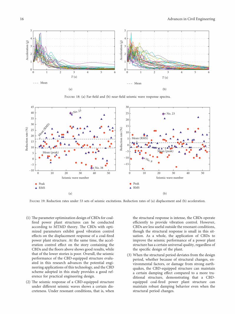

International Journal of
AerospaceEngineeringHindawiwwwhindawicom Volume 2018
RoboticsJournal of
Hindawiwwwhindawicom Volume 2018
Hindawiwwwhindawicom Volume 2018
Active and Passive Electronic Components
VLSI Design
Hindawiwwwhindawicom Volume 2018
Hindawiwwwhindawicom Volume 2018
Shock and Vibration
Hindawiwwwhindawicom Volume 2018
Civil EngineeringAdvances in
Acoustics and VibrationAdvances in
Hindawiwwwhindawicom Volume 2018
Hindawiwwwhindawicom Volume 2018
Electrical and Computer Engineering
Journal of
Advances inOptoElectronics
Hindawiwwwhindawicom
Volume 2018
Hindawi Publishing Corporation httpwwwhindawicom Volume 2013Hindawiwwwhindawicom
The Scientific World Journal
Volume 2018
Control Scienceand Engineering
Journal of
Hindawiwwwhindawicom Volume 2018
Hindawiwwwhindawicom
Journal ofEngineeringVolume 2018
SensorsJournal of
Hindawiwwwhindawicom Volume 2018
International Journal of
RotatingMachinery
Hindawiwwwhindawicom Volume 2018
Modelling ampSimulationin EngineeringHindawiwwwhindawicom Volume 2018
Hindawiwwwhindawicom Volume 2018
Chemical EngineeringInternational Journal of Antennas and
Propagation
International Journal of
Hindawiwwwhindawicom Volume 2018
Hindawiwwwhindawicom Volume 2018
Navigation and Observation
International Journal of
Hindawi
wwwhindawicom Volume 2018
Advances in
Multimedia
Submit your manuscripts atwwwhindawicom

![EXERGY DIAGNOSIS OF COAL FIRED COMBINED … · Exergy Diagnosis of Coal Fired Combined Heat and Power ... in coal fired combined heat and power plant have ... Thermoeconomic [2] analysis](https://img.pdfslide.us/doc/110x75/5b4f746a7f8b9a1b6e8c4949/exergy-diagnosis-of-coal-fired-combined-exergy-diagnosis-of-coal-fired-combined.jpg)