Embed Size (px)
Citation preview

CO 2009 Optimisation and Troubleshooting of Compressors and Turbines Aberdeen, U.K. 3-4 February 2009
Optimization & Revitalization of Existing Reciprocating Compression Assets
W. Norman Shade, PE ACI Services Inc.
Many reciprocating compressors in North America and throughout the world have been in service for decades, some operating for more than half a century. Most older models are no longer optimal, and many are not dependable for current process requirements. Over time, technology has improved and energy costs have increased, making it economically attractive to optimize and revitalize existing compression assets with components that take advantage of modern technology. Efficiency, reliability and maintainability can be greatly improved through custom engineered solutions. Changes may range from conversion to better compressor valves, to the addition of properly designed automatic unloading devices for better control, to the installation of new purpose-built compressor cylinders and components, to the complete reapplication of an entire compression system to a new service. Even relatively new compressors can become inefficient and mis-matched as production needs change. In other cases, from the time the units were installed, actual operating conditions never quite matched the design conditions specified when the equipment was ordered. In still others, manufacturers may have missed the mark when designing and applying their products, so that the equipment underperforms or is unreliable for its intended service. Whatever the reason, changing valves or cylinders, adding unloaders and automatic control, or reapplying, existing reciprocating compressors is frequently necessary and justifiable. In the case of newer compressors, the OEMs may have standard cylinders that can be retrofitted to their frames, however that usually requires expensive changes to the process piping, pulsation vessels, and cylinder mounting. In the case of mature compressor models that are no longer in production, new OEM cylinders tend to be expensive and have long lead times, if available at all. In some applications, when new compressors are selected or used compressors are redeployed, the standard OEM cylinder line-up may not include the optimal cylinder bore size or working pressure rating for the desired operating conditions. Any of these situations are candidates for custom engineered cylinders and unloading devices that provide cost-effective solutions for preserving the value and reducing the operating cost of existing compression assets. NEW CUSTOM ENGINEERED REPLACEMENT CYLINDERS With over 30 years of designing and manufacturing custom engineered compressor cylinders, internal components, valves, and unloading systems, the author’s company has helped a large number of compressor users improve their competitive edge by providing creative solutions that improve their existing compression assets to improve performance, efficiency, reliability, maintenance cost, and safety. These efforts have provided solutions to operating problems, have improved the performance and have increased the reliability of reciprocating compressors. The extensive experience in designing and manufacturing custom engineered compressor cylinders is represented in Figures 1 and 2 below. Custom engineered cylinders have been applied on all major brands of compressors ranging from small 3.0 in. (76.2 mm) stroke, 1800 rpm high-speed models to giant 20.0 inch (508.0 mm) stroke, 330 rpm frames, with bore sizes ranging from 1.33 to 36.0 in. (33.8 to 914.4 mm), and working pressures from as low as 50 psig (3.5 bar) to as high as 12,000 psig (827.4 bar) for upstream, gas transmission, gas storage, chemical process, refinery, high-pressure air and other services. New compressor cylinders can be custom engineered and purpose built to meet customer specifications or to solve problems with existing OEM designs. In most cases, the cylinders can be “bolt-in” replacements to match existing process piping connections and mounting locations, which avoids expensive system piping and foundation modifications. Cylinders can be jacketed (water cooled) or non-jacketed (air cooled) and made from appropriate material for the application. Ductile iron castings are most commonly used in recent years, although gray iron, steel or stainless castings are also used, as are steel and stainless steel forgings. Reduced hardness materials are available for sour gas and other applications requiring NACE specifications. Cylinder bores may be supplied in the virgin material condition, ion nitride hardened for improved wear resistance, or lined with a replaceable sleeve. Depending on the requirements, existing internal components may be reusable, however new

CO 2009 Optimisation and Troubleshooting of Compressors and Turbines Aberdeen, U.K. 3-4 February 2009
valves, piston rod packing and maintenance friendly piston and rod assemblies are often included. A wide range of manual and automatically controlled clearance volume pockets and end deactivators are also available, custom engineered for the specific application requirements.
ACI Services, Inc.Custom Cylinder Designs
Bore (in.) v. Stroke (in.)
0
5
10
15
20
25
30
35
40
0 2 4 6 8 10 12 14 16 18 20 22Stroke (in.)
Bor
e D
iam
eter
(in.
)
ACI Services, Inc.Custom Cylinder Designs
MWP (psig) v. Bore Dia. (in.)
10
100
1,000
10,000
100,000
0 2 4 6 8 10 12 14 16 18 20 22 24 26 28 30 32 34 36 38 40Bore Diameter (in.)
Cyl
inde
r MW
P (p
sig)
Fig. 1: Custom cylinder experience – bore dia. vs. stroke Fig. 2: Custom cylinder experience – pressure rating vs. bore diameter Case History 1: Increased Pipeline Compressor Capacity. In the first example, a mid-continent USA natural gas pipeline operator had several existing Clark HBA and HRA integral engine compressors with cylinders that no longer served the operating needs of the compressor station. The customer specifications dictated an approximate 32% increase in bore size in a new cylinder that provided maximum operating efficiency. In addition, the cylinder was to have external dimensions that permitted the use of the existing piping system, cylinder supports and foundation. It was readily apparent that a conventional cylinder design would never meet all of the requirements of the specification. The OEM, who supplied the engines, agreed, but offered a conventional design that did not meet the specifications. The Four-PosterTM cylinder offering was sufficiently unique that the author’s company received a patent on the new design.
Fig. 3: Retrofitting custom engineered cylinders increased bore size by 32% on this 17 in. (431.8 mm) stroke Clark integral compressor.
In addition to meeting all the specification requirements, the cylinders were offered at a lower price and shorter delivery than offered by the OEM. In this design, all valves were accessible from the top of the cylinder and the front and rear head, piston assembly, liner and packing case were accessible from the front of the cylinder. A total of 42 new 12.50 inch (317.5 mm) bore, 1000 psig (69.0 bar) cylinders were retrofitted onto multiple 17.0 in. (431.8 mm) stroke compressors. Closed loop tests certified the efficiency of the cylinders. Significant savings resulted from the re-use of the piping and cylinder supports and the absence of foundation changes. Subsequent to the supply of these 42 cylinders, other orders were received for four more identical cylinders and sixteen cylinders with slight modifications for another OEM’s 14.0 in. (355.6 mm) stroke engines. All cylinders delivered trouble free service.
Case History 2: Improved Service Life. A USA Gulf Coast chemical plant had a Worthington BDC off gas compressor with cast iron cylinders that were constantly under chemical attack from extremely corrosive gas. Cylinder life was typically only 3 to 5 years, and the OEM had not resolved the problem to the satisfaction of the customer, who required a functionally equivalent cylinder design that would directly replace the existing cylinder to the extent that all other parts of the assembly could be re-used with the new cylinder body.

CO 2009 Optimisation and Troubleshooting of Compressors and Turbines Aberdeen, U.K. 3-4 February 2009
The customer had attempted to produce replacement cylinders of the same geometry in a ni-resist material, however, the cylinder geometry and jacketed design were not compatible with ni-resist foundry practices and requirements. As shown in Figure 4, the author’s company redesigned the exterior of the jacketed, 400 psig (27.6 bar), 12.0 in. (304.8 mm) bore, 9.5 in. (241.3 mm) stroke cylinder body to simplify and enhance foundry procedures. Proper core support and clean out and pattern orientation in the mold resulted in sound castings when produced in ASTM A316 series stainless steel. The change to A316 stainless steel resolved the corrosion problems and eliminated the periodic safety inspections that had been required with the original cast iron cylinders. For more than 20 years, the replacement cylinders have been more productive, and maintenance costs have been reduced. Similar replacements of this type were subsequently provided for 19.5 and 7.75 in. bore (495.3 and 196.9 mm) cylinders for adjacent stages.
Fig. 4: This custom engineered ASTM A316 cast stainless steel cylinder eliminated a severe corrosion problem with the cast iron cylinder that it replaced.
Case History 3: Providing Safe and Reliable Production Operation. A large Cooper Bessemer V250 integral engine compressor in an Austral-Asian fertilizer production plant had experienced repeat failures of the 3rd stage
5 syn gas cylinder. The 6.50 in.
(190.5 mm) lined bore diameter, 20 in. (508.0 mm), 6000 psig (413.7 bar) forged steel cylinder was a design that employed transverse tie-bolts for reinforcement. After several years of service, cracks would originate in the discharge valve pockets and migrate to the tie-bolt clearance holes as shown in Figure 5. A thorough engineering analysis revealed very high stresses and unacceptable fatigue safety factors in the valve seats as shown in Figure 7. Since the high-pressure 3rd stage was normally operating at 93% of rated rod load, and the 1st and 2nd stages were lower at 77% and 59%, respectively, a performance study was completed to determine an optimal bore size for the new 3rd stage cylinder. Interacting with the plant engineering staff, it was agreed that the new cylinder bore Fig. 5: 3rd stage syn gas cylinder showing location of leak detection. diameter could be reduced to 6.00 in.(152.4 mm), which cut the normal normal operating rod load to 84% of rated, while still maintaining acceptable rod loads of 79% and 68%, respectively, on the 1st and 2nd syn gas stages. It was also determined that the low molecular weight permitted a reduction in valve diameter, which significantly reduced the preload that on the valve cap bolting, while also increasing the section thickness in the critical corners where the valve pockets intersected the main bore. A new 6.00 in. (152.4 mm) AISI 4140 forged steel bolt-in replacement cylinder was designed and extensively analyzed to achieve acceptable fatigue safety factors. The new jacketed cylinder, shown in Figure 6, was fully

CO 2009 Optimisation and Troubleshooting of Compressors and Turbines Aberdeen, U.K. 3-4 February 2009
Fig. 7: Finite element stress analysis of high-pressure cylinder body showing high stresses in valve seat fillets.
Fig. 6: New AISI 4140 forged steel cylinder with water jacket, weighing more than 10,000 lb. (4335 kg).
machined from a solid block forging that was 3 in. (76 mm) thicker than the original cylinder. The problematic tie- bolts were eliminated, and the critical valve pocket fillet geometry was carefully controlled and then shot peened after machining to provide beneficial compressive preload stresses. Water jacket side covers were fully machined from aluminum plate material to eliminate a corrosion problem that was prevalent with the original cast iron side cover design.
Case History 4: Eliminating Extremely Serious Piston Failures. A major oil company was experiencing frequent and rapid piston failures on the 2nd stage of a reapplied 4000 hp (2983 kw) Superior W76 compressor
used for sour gas lift service on an offshore platform. Not only was downtime causing six figure daily production losses, operating personnel were fearful that the piston failures could lead to a breach of the lethal sour gas, which would be extremely dangerous on an offshore platform. The OEM and another compressor service company had both tried to solve the problem with new pistons, but failures continued in as little as 8 days of operating time. Upon being consulted for help, the author’s company conducted a thorough assessment and found that very high 2nd stage operating temperature, coupled with rod loads that were at or above the manufacturer’s rating, were the root causes of the rapid, catastrophic failures of the 18.0 in. (457.2 mm), 7.0 in. (177.8 mm)
Fig. 8: Multi-piece Piston finite element stress plot.
Fig. 9: Original 18.0 in. (457.2 mm) OEM 2nd stage cylinder [left] that experienced frequent rapid, catastrophic piston failures due to a mis-application..
Fig. 10: New 18.125 in. (460.4 mm) bolt-in 2nd stage replacement cylinder.

CO 2009 Optimisation and Troubleshooting of Compressors and Turbines Aberdeen, U.K. 3-4 February 2009
stroke multi-piece aluminum and ductile iron pistons. As shown in Figure 9, the cylinder was an unusual shape that resulted in a very short piston length relative to the diameter. A finite element stress analysis, as shown in Figure 8, showed that the original piston design had a fatigue safety factor of less than 1.0 at the required operating conditions, which explained the rapid failures. Unfortunately, the alternatives for resolving the problem were very limited. The short cylinder and OEM limits on the permissible reciprocating weight precluded the use of a stronger, less temperature sensitive ferrous material piston. Adding interstage cooling to reduce the 194°F (90°C) suction temperature was not practical on the offshore platform due to space limitations. The OEM did not have an alternative cylinder that would solve the problem, and lead time for a complete new replacement compressor package was about 18 months at the time. A custom engineered replacement cylinder was determined to be the preferred solution, but lead time was also prohibitively long. Concurrent design and analysis efforts established that a one-piece solid aluminum piston, although not having infinite life, would operate for a longer and reasonably predictable period of time. This was adopted as a temporary measure until a new replacement cylinder could be designed and manufactured. With the one-piece pistons providing additional time for development of a permanent solution,
Fig. 11: New 21.0 in. *533.4 mm) bolt-in 1st stage replacement cylinders with manual variable volume clearance pockets.
further review of the operating conditions of the 1st and 2nd stages showed that further benefits were achievable by changing the two 1st stage cylinders along with the 2nd stage. By changing the two 1st stage cylinders from 20.0 in. (508.0 mm) to 21.0 in. (533.4 mm) and the 2nd stage from 18.0 in. (457.2 mm) to 18.125 in. (460.4 mm), a better balance of rod loads and interstage temperatures was achieved, while providing the compressor with an increased capacity rating that was an unexpected bonus for the operator. All three of the new ASTM A395 ductile iron cylinders were designed longer to accommodate longer ductile iron pistons that were capable of the required loading. In order to do this while also maintaining process piping connection points, special cast ductile iron offset adapters were designed and manufactured for the suction and discharge connections. The pistons were high-performance, two-piece ductile iron castings with internal ribs. Both the cylinders and the pistons were extensively analyzed with finite element stress models. Standard Ariel variable volume clearance pockets were adapted to the new 1st stage cylinders. The new cylinders received hydrostatic tests at 1.5 times working pressure, followed by helium submersion tests at working pressure. Field-installed on the original frame as shown in Figures 10 and 11, the new cylinders have completely eliminating the piston failures, while providing the production platform with several percent more capacity than was achievable with the original OEM cylinder configuration. Case History 5: Increasing Compressor Efficiency and Throughput: A single-stage, gas engine driven, Dresser Rand 6HOS-6 compressor was applied in natural gas pipeline service. The operating conditions of the pipeline were such that the engine driver was fully loaded making it the limiting factor for throughput of the com-pressor station. Performance tests of the original OEM cylinders, which were misapplied, showed that valve losses were very high for the low ratio application because of insuf-ficient valve sizes and gas passages in the OEM cylinders being used on the frame. New 10.5 in. (266.7 mm) bore, 6.0 in. (152.4 mm) stroke, 1200 psig (82.7 bar) bolt-in replacement cylinder assemblies were designed with larger valves and generous internal gas passages. As shown in Figure 12, the new cylinders were installed in place of the original cylinders in less than two days, maintaining all existing process piping connections and mounting. Performance tests of the new cylinders showed an efficiency gain of about 10%, bettering the guarantee of 8% and leading to a corresponding 10% throughput gain for the compressor station.

CO 2009 Optimisation and Troubleshooting of Compressors and Turbines Aberdeen, U.K. 3-4 February 2009
Fig. 12: The first of six new high efficiency bolt-in replacement cylinders [left] is installed on a six-throw, single-stage D-R 6HOS-6 frame. Two of the original OEM cylinders are shown on adjacent throws [right] prior to replacement. Case History 6: Increasing Cylinder Working Pressure. A USA natural gas storage facility had a requirement for increased operating pressure. The compression was provided by four Cooper Bessemer GMVA-10 integral engine compressors each having four older style vertically-split valve-in-head cylinders. The OEM, as well as the author’s company, was asked to re-rate the original cylinders; however with large gasketed joints as shown in Figure 13, the cylinders were only marginally adequate for their original pressure rating and therefore incapable of further uprating. The OEM offered new higher-pressure cylinders, however, they would require major modifications to the ASME coded pulsation bottles and process piping, greatly increasing the cost and the install-
Fig. 13: Original OEM 1100 psig (75.8 bar) valve-in-head type cylinders.
Fig. 14: New custom engineered 1200 psig (82.7 bar) bolt-in replacement valve-in-barrel type cylinders.
ation time for the project. The author’s company measured critical interface dimensions on site without removing the old cylinders and then designed new 12.0 in. (304.8 mm) bore, 14.0 in. (355.6 mm) stroke, 1200 psig (82.7 bar) ASTM A395 cast ductile iron bolt-in replacement cylinders as shown in Figure 14. The design was able to accommodate the use of the original double deck valves, packing cases and automatic fixed volume clearance pockets. As the new cylinders were completed, the original valves, packing, and pockets were reconditioned, and the valve pocket volume bottles were re-rated for the higher working pressure. The field conversion went smoothly and the customer’s facility was available, on schedule, to handle the higher operating pressure.

CO 2009 Optimisation and Troubleshooting of Compressors and Turbines Aberdeen, U.K. 3-4 February 2009
Case History 7: Improving Safety and Maintainability. Another USA natural gas storage facility required increased operating pressure. The facility had five 1940s vintage Cooper Bessemer GMV compressors with valve-in-head cylinders. As shown in Figure 15, the original cylinders had two separate suction and two separate discharge connections, and the cylinders were vertically split so that the outboard suction and discharge flange connections had to be disturbed whenever it was necessary to access the piston, rod or packing for maintenance. Although the OEM indicated that a modest pressure re-rate of the cylinders might be possible, the station opera-
Fig. 15: Original problematic valve-in-head cylinders required disturbing the outboard piping connections to access the piston, piston rod and packing.
Fig. 16: New bolt-in replacement valve-in-barrel cylinders reused original valves, packing and cylinder unloaders. Piping connections are no longer disturbed for piston, rod and packing maintenance.
tors were concerned about the safety since the existing cylinders sometimes had gasket leakage problems at the original pressure rating. They wanted to avoid any gas piping or pulsation bottle changes and they wanted higher pressure cylinders that eliminated the problematic gaskets and the cumbersome and costly maintenance procedures that required disturbing gas piping connections to access the cylinder bore. In order to meet this challenge, a special valve-in-barrel cylinder design was developed, and 20 new 7.0 in. (177.8 mm) bore, 14.0 in. (355.6 mm) stroke, 2000 psig (137.9 bar) ASTM A395 cast ductile iron, jacketed, cylinders were manufactured and installed on the existing compressors as shown in Figure 16. Valves, packing and unloaders were reconditioned and reused in the new cylinders. Case History 8: Emergency Replacement of Obsolete Cylinders. A chemical plant had an emergency when a critical Pennsylvania ATP off gas compressor unexpectedly developed internal process gas leaks into the cooling
water jacket. The OEM no longer had the original cylinder body pattern, so their lead time for a new cylinder approached one year. Since loss of this compressor required shutting down the entire plant, emergency temporary repairs were made to the cylinder, and the author’s company was contacted to provide a new cylinder. Critical interface measurements were made on site, and a new design 20.5 in. (520.7 mm), 11.0 in. (279.4 mm) stroke, 150 psig (10.3 bar) cylinder was expedited from ASTM A395 cast ductile iron to strengthen the weak, corrosion sensitive sections. The new cylinder was delivered in only 20 weeks, including the time for design, pattern construction, casting, machining, hydrostatic testing and installation of a new ni-resist liner (Figures 17 - 18).
Fig. 17: Liner installation. Fig. 18: Finished cylinder. Case History 9: Extending OEM Standard Cylinder Offerings. An upstream production company had a relatively new Ariel JGJ/6 compressor used for acid gas injection to stimulate oil production. The 600 hp (447 kw), 1500 rpm compressor was originally configured as a 5 stage unit. Once the field was operating, however, it became evident that production could be enhanced by increasing the injection pressure to a level that exceeded the capability of the compressor as originally configured. It was determined that a 6th compressor stage was required, but the OEM did not have a suitable high-pressure cylinder for that particular frame.

CO 2009 Optimisation and Troubleshooting of Compressors and Turbines Aberdeen, U.K. 3-4 February 2009
In addition, the aggressive nature of the acid gas required the use of material produced to NACE specifications; and the limited physical size constraints required a higher material strength than could be achieved with the use of reduced hardness alloy steels. 17-4PH stainless steel was therefore the material of choice for the new cylinder. With the approval of the OEM, the author’s company designed and manufactured a special 2.75 in. (69.9 mm) bore, 3.5 in. (88.9 mm) stroke, 3000 psig (206.8 bar) cylinder. The tail rod design, which
Fig. 19: Special 3000 psig (206.8 bar) 17-4PH stainless steel tail rod cylinder designed for acid gas injection service.
is shown in Figure 19, was completely machined from a solid 17-4PH double H1150 heat treated stainless steel forging. This cylinder was added to the original compressor as a 6th stage to increase final injection pressure. Case History 10: Filling gaps in OEM Standard Cylinder Offerings. A distributor packager of new Gardner Denver and remanufactured Joy 7.0 in. (177.8 mm) stroke high-pressure air compressors used in portable diesel engine driven compressor packages for the rotary drilling industry was encountering application conditions for which the OEM cylinders were not optimally suited. Given the maturity of the compressor product line, the OEM was not very interested in modifying the existing cylinder designs or creating new cylinder designs.
The author’s company reviewed the range of required application conditions, measured the mounting interface dimensions, and subsequently developed a family of new 7.0 in. (177.8 mm) cylinders that fit the compact vee-type Joy and Gardner Denver compressor frames and that were optimally sized for the air drilling application requirements. The bore sizes of the ASTM A395 cast ductile iron, jacketed cylinders, ranged from 3.5 to 4.5 in. (88.9 to 114.3 mm) with a working pressure of 2500 psig (172.4 bar). Cylinders are now supplied on a regular basis to meet this distributor packager’s needs, and additional bore sizes are being considered to further expand the range of pressures and flow rates offered to meet the needs of the drilling market as shown in Figure 20.
Fig. 20: 2500 psig (172.4 bar) cylinder family developed to fill a gap in the OEM’s offerings for high-pressure air drilling service.
Many more examples can be provided, however, the forgoing list shows the various kinds of applications for which new custom engineered, purpose built reciprocating compressor cylinders can be attractive alternatives for optimizing and revitalizing existing compression assets. RE-APPLIED COMPRESSOR CYLINDERS Although new, custom engineered and purpose-built cylinders can provide optimal performance and reliability, there are frequent examples where surplus or previously decommissioned cylinders can be reconditioned and re-applied onto existing compressor frames. New OEM cylinders can also be installed on different OEM frames that have similar strokes and rod diameters. Of course, diligent and experienced engineering design is required to match the different mounting, bolting, piston rod and, if the stroke is different, the piston. Consideration must also be given to matching reciprocating weights with the compressor frame’s capability. Maximum pressure ratings, Internal gas and inertia rod load ratings, and pin reversal requirements must be considered in the reapplication as well. Done properly, reapplication of cylinders is a reliable alternative that can often reduce the capital cost and will almost always reduce the cylinder lead time. Several examples demonstrate the potential of this engineered approach.

CO 2009 Optimisation and Troubleshooting of Compressors and Turbines Aberdeen, U.K. 3-4 February 2009
Case History 11: Adapting Remanufactured Cylinders to An Existing Compressor. A natural gas pipeline transmission station had two 1950s vintage I-R KVG 10/3 integral engine compressors in service. Although having a provision for three compressor throws, only two of the throws were previously equipped with cylinders, the center throw being unused for more than 50 years. Conditions had changed over that period of time so that
ders produced no results either, although the author’s company was able to find two similar 15.0 in. (381 mm) stroke I-R process cylinders, Figure 21, that had the same flanges and distance between flanges. It was determined that with modifications to the combination crank end head and distance piece, the process cylinders could be adapted to fit the existing KVG compressors. A performance model, Figure 22, showed that the cylinders would meet the required operating conditions if all cylinders were modified by lining to a 10.16 in. (258.1 mm) bore diameter. Having no time to lose, two used cylinders were purchased and taken to the factory for cleaning, inspection and hydrostatic testing to confirm that the cylinder bodies were sound. The cylinders were then modified to fully restore all fit dimensions, sealing surfaces and threads to ensure their integrity for the reapplication. All new bolting, seals and gaskets were installed. After machining, a second hydrostatic test of the remanufactured cylinders was conducted at 1.5 times maximum working pressure, as shown in Figure 23. Concurrent with the completion of the “new” remanufactured cylinders, new liners, non-lube piston and rod assemblies, double deck poppet valves, valve cages, valve caps, outer end automatic fixed volume clearance pocket heads, and highly efficient radial poppet suction valve deactivators were designed and manufactured for the four existing cylinders on the two compressors as well as for the two remanufactured cylinders. A complete API 618 design approach 2 pulsation study was also conducted on the entire system with the new configuration. This study revealed high pressure drops in the existing plant suction pulsation control arrangement with the higher flow, three cylinder configuration, and mitigating actions were quickly identified and added to the conversion plan.
Fig. 21: One of two used I-R cylinders prior to the remanufacturing process.
the 600 hp (447 kw), 330 rpm compressors were no longer fully loaded. The pipeline operator had determined that, by adding another identical cylinder to the inactive throw in parallel with the existing cylinders in a single-stage configuration, the engine could be fully loaded to increase the station’s capacity. Inquiries were made to the OEM and several other companies. The OEM still had the original pattern and was able to quote new identical cylinders, however lead time for that option was about 40 weeks. The author’s company also offered to design and manufacture new bolt-in replacement cylinders, however, the best possible lead time was 26 weeks. Neither of these alternatives were adequate for the operator’s requirement to have the conversion completed so that both compressors would be in service within no more than 20 weeks after the release of the order. An extensive search for identical used or surplus cylin-
Fig. 22: Performance model for 3-cylinder, single-stage I-R compressor showing all load steps required for system flexibility without overloading at the maximum specified discharge pressure.
Fig. 23: Remanufactured cylinders with new fixed volume clearance pocket heads and valve caps undergoing an 8-hr factory hydrostatic test

CO 2009 Optimisation and Troubleshooting of Compressors and Turbines Aberdeen, U.K. 3-4 February 2009
Case History 12: Mixing Used OEM Cylinders and Frames to Optimize Performance. A natural gas processing plant wanted to reapply an existing 2000 hp (1491 kw), 900 rpm gas engine and compressor package for a propane refrigeration process. Process conditions were fixed, so that cylinders had to be carefully selected to match the operating requirements. Using the preferred 6.0 in. (152 mm) stroke Superior WH64 compressor frame, initial performance sizing resulted in a selection of 25.5 in. (648 mm) diameter Superior cylinders for both the 1st and 2nd stages, however the 2nd stage cylinders would have had to operate very close to their working pressure limit. The same concern existed for the 20.0 in. (508 mm) 3rd stage cylinder. The OEM was not interested in producing special cylinders for a single unit, and no used cylinders with an adequate working pressure could be found.
Fig. 25: Adaptation of 5.5 in. (140 mm) stroke Ariel cylinders to a Superior 6.0 in. (152 mm) stroke Superior compressor frame.
Fig. 26: 2000 hp (1491 kw), 900 rpm, gas engine driven 3-stage propane refrigeration compressor.
As a result, a new 6.5 in. (165 mm) stroke Ariel JGC/4 compressor was considered, but this resulted in concern about the reliability of the valves with the heavy propane gas. Switching to a 5.5 in. (140 mm) stroke Ariel JGD/4 compressor made the valve reliability more promising, but it could not produce the required flow with the available standard Ariel cylinders. It was finally determined that the solution could be optimized by adapting Ariel JGD cylinders to fit on the Superior WH64 compressor frame. Ariel 22.0 in. (559 mm) diameter JGD cylinders were selected for the 1st stage and the two 2nd stage cylinders, and an Ariel 19.625 in. (499 mm) diameter JGD cylinder was selected for the 3rd stage. Used Ariel cylinders were found that could be reconditioned for all but one of the
When all components and cylinder assemblies were completed, the station was taken off line for the conversion. The suction and discharge bottles were removed and taken to an ASME code welding shop for addition of the incremental connections, followed by recertification. Some simple piping modifications were also made to mitigate the pressure drop problem that had been revealed by the pulsation study. Using special field machining equipment, the existing liners were machined out of the existing cylinders without removing them from the compressor. New liners and the other new components were then installed along with the incremental remanufactured cylinders. The revised bottles were reinstalled and the system was completed and commissioned on schedule. One of the completed units is shown in Figure 24. At this time the compressors have been in service for over 3 years.
Fig. 24: One of two reconfigured KVG units after adding a 10.16 in. (258.1 mm) diameter remanufactured cylinder [center] and adding new clearance pockets, radial poppet suction valve deactivators, and other new components to all the cylinders.

CO 2009 Optimisation and Troubleshooting of Compressors and Turbines Aberdeen, U.K. 3-4 February 2009
four that were required, however since the JGD cylinders are designed for a 5.5 in. (140 mm) stroke, their use on the Superior frame required redesigning the piston and piston rod to accommodate the longer stroke. In addition, special mounting adapters were required to match the different bolt patterns on the cylinders and the frame, as shown in Figure 25. The author’s company provided the special engineered components to accomplish this adaptation. At this time, the unit, shown in Figure 26, has been in service for approximately 3 years. Case History 13: Extending Obsolete Compressor Life with New OEM Cylinders. A natural gas production company had an obsolete 6.0 in. (152.4 mm) stroke Knight KOCA-2 compressor frame with fabricated (welded)
Fig. 27: Obsolete KOCA/2 compressor prior to conversion. Fig. 28: Loading map for new 2-stage configuration.
steel cylinders, as shown in Figure 27. The cylinders were susceptible to cracking problems in service and were no longer safely repairable. The original compressor OEM had been out of business for more than two decades, so neither new nor repairable used cylinders were realistic alternatives. Lead time for new compressor packages was close to 52 weeks and production losses would be substantial if the compressor could not be returned to service in a much shorted time. The author’s company was asked to evaluate alternatives. Although new custom engineered cylinders were an option, lead time was still somewhat longer than desirable, considering the cost of lost production. A much shorter lead time was possible by adapting new Ariel JGK cylinders to the KOCA frame. As long as changes were going to have to be made to the cylinders, bottles and piping anyway, the producer decided that it would be desira-
Fig. 29: Obsolete KOCA/2 frame with new Ariel cylinders applied.
ble to optimize the compression system to accommodate an anticipated suction pressure decline over time, while still utilizing as much of the gas engine driver power as practical to deliver flow. This ultimately required converting from a single-stage to a 2-stage configuration with 8.375 in. (212.7 mm) and 6.25 in. (158.7 mm) bore cylinders, which provided optimal coverage of the operating conditions and maximum driver power utilization as shown in Figure 28. Even more importantly in this case, the solution could be implemented in less than 20 weeks time. New 5.5 in. (139.7 mm) stroke Ariel cylinders were converted to 6.0 in. (152.4 mm) stroke with new custom-engineered piston and rod assemblies, rod packing and wiper assemblies, and mounting adapters to match the KOCA frame. New ASME coded pulsation bottles were also designed and manufactured, as shown in Figure 29, and piping modifications were made to adapt to the original skid and utilize the process gas cooler. An API 618 Design Approach 2 pulsation study was conducted, and the system piping design was tuned to provide effective

CO 2009 Optimisation and Troubleshooting of Compressors and Turbines Aberdeen, U.K. 3-4 February 2009
pulsation control over the broad operating range. The unit was been in service for more than two years, and additional units are now being considered for similar conversions. Case History 14; Completely Reconfiguring an Existing Compressor. An existing 600 hp (447kw), 588 rpm, 4-throw, 3-stage, 7 in. (177.8 mm) stroke Joy WB14 compressor was originally configured as shown in Figure 30 to compress 1303 cfm (42.5 m3/min) of bone dry nitrogen. Requirements changed such that only 314 cfm (10.3 m3/min) was required. The cost of recyling 76% of the flow was not acceptable, but the cost of a complete new, but smaller, machine was equally difficult to justify. The owner/operator wanted to reconfigure the existing compressor at minimal cost to operate more efficiently at the lower flow rate. In order to evaluate possible alternatives, a complete performance model was developed for the existing configuration having two16.0 in. (406.4 mm), one 10.5 in. (266.7 mm) and one 7.0 in. (177.8 mm) cylinders. The model was then revised in an iterative manner to evolve a solution that let replacing the two 1st stage cylinders with reconditioned used 8.0 in. (203.2 mm) cylinders, moving the original 7.0 in. (177.8 mm) 3rd stage cylinder to the 2nd stage, and installing a reconditioned used 4.0 in. (101.6 mm) cylinder on the 3rd stage. The bottles were modified with new flanges to adapt to the smaller cylinders. Most of the existing piping was reused by adding adapter sections.
Fig. 30: Prior to reconfiguring, this oversized 3-stage Joy WB14 nitrogen compressor required 76% of the flow to be recycled.
Fig. 31: The reconfigured unit was sized to meet the process requirements without significant recycled flow.
By reconfiguring the compressor with reconditioned used cylinders and reapplying one of the existing cylinders, as shown in Figure 31, this solution provided a cost effective solution that saved significant operating cost and preserved the original investment of the compressor frame, motor and the balance of the system. COMPRESSOR OPTIMIZATION AND AUTOMATION WITH CUSTOMIZED UNLOADING DEVICES In addition to hundreds of successful examples of custom designed new cylinders and countless innovative adaptations and reapplications of new and used OEM cylinders, there are even more examples of compressor optimization with automatically actuated devices, often called unloaders, that control the load and flow. Case History 15: Automation of Propane Refrigeration Compressor. A natural gas processing plant used a
400 hp (298 kw) Ajax compressor with no automatic control. The 2-stage, 2-throw unit served as the low-pressure stage of a multi-unit propane refrigeration system. As ambient conditions changed, the propane boil-off rate varied, necessitating manual adjustments of the compressor’s clearance pockets. Since the unit was not attended 24/7, the operators kept the unit under-unloaded so that it could handle upsets without shutting down. Unexpected shutdowns stopped the liquid stripping process and led to serious problems downstream from the gas plant. The solution involved the combination of a discrete step unloader and an infinitely variable unloader providing, in essence, infinite variability over a broad range of operating conditions, as shown in Figure 31.
Fig. 31: Fine unloading steps for a wide range of operating conditions are provided by a combination of fixed and variable unloaders.

CO 2009 Optimisation and Troubleshooting of Compressors and Turbines Aberdeen, U.K. 3-4 February 2009
Fig. 32: New automatic clearance pockets added to propane refrigeration compressor.
This gave the plant maximum compressor loading (and maximum plant refrigeration and liquid stripping capacity) without the risk of unexpected shutdowns. The compressor conversion involved installing a hydraulically actuated head end variable volume clearance pocket on the 1st stage cylinder along with a pneumatically actuated fixed volume clearance pocket on the head end of the 2nd stage cylinder as shown in Figure 32. The control pressure for the hydraulically actuated variable volume unloader was provided by the use of discharge pressure acting on an external accumulator containing hydraulic fluid separated by a bladder. This approach eliminated the need for separate pumps and power requirements. The control pressure for the fixed volume pocket was provide by plant are pressure. Control algorithms, that were derived from a robust reciprocating compressor performance modeling program developed by the author’s company, were programmed into a PLC, which then automatically controlled the unit with the two unloaders. The conversion required about two days of installation time, and it has been operating continually for more than 3 years.
Case History 16: Pipeline Compressor Automation. A pipeline operator required the reapplication of five large Clark TCV-12 and TLA-6 19.0 in. (483 mm) stroke integral engine compressors. An increased range of pressure ratios required a reduction of existing fixed clearance. The budget was tight and required reusing as much of the
Fig. 33: One of five large 19.0 in. (483 mm) stroke integral engine compressors that were completely configured for automatic operation with a broad range of pressure ratios.
existing hardware as possible. The author’s company modeled the compressor performance and developed an optimum unloading configuration. The front and rear heads and liner ports were reconfigured to reduce the cylinder fixed clearance. The large 14.0 in. (355.6 mm) diameter cylinders were lined down to 12.5 in. (317.5 mm). The compressor valves were redesigned to maximize the lift area and minimize fixed clearance. A total of 116 fixed volume clear-
ance pocket unloaders having volumes of 150 in3, 300 in3, 600 in3, or1500 in3 (2.5, 4.9,9.8 or 24.6 L) provided the flexibility necessary to meet the wide range of compression ratios associated with the new application. Novel piston de-signs permitted the use of existing piston rods while pro-viding piston to rod attachment features that resulted in easier and safer assembly techniques. The revamped units, shown in Figure 33, provided the required performance, which was more flexible and reliable than the OEM’s offering. Case History 17: Replacement of Variable Speed Engine with Synchronous Electric Drive. A natural gas producer had a 2-throw, 2-stage Superior W-72 reciprocating compressor driven by a 1600 hp (1193 kw), 900 rpm gas engine that had become obsolete, was inefficient and was expensive to maintain. In addition, due to local air quality restrictions, and electric motor drive was considered as a preferred replacement for the engine drive. The primary mode of flow control was via speed control on the engine, which provided a high level of flexibility. However the operator did not want the complexity or cost of a variable frequency electric motor drive. Use of a constant speed, synchronous motor drive, then, appeared to be impractical for the application that had to have a wide range of flow control capability. The author’s company was requested to propose unloading equipment that would provide optimal flexibility at reasonable cost. After weighing various options, the preferred solution involved

CO 2009 Optimisation and Troubleshooting of Compressors and Turbines Aberdeen, U.K. 3-4 February 2009
simply replacing the outer heads of each compressor cylinder and adding plug-type suction valve deactivators to the head ends of both cylinders. As shown in Figure 34, the new 1st stage head was configured with a custom engineered design having 3 different clearance pockets of 73, 146 and 292 in3 (1.2, 2.4 and 4.8 L) respectively.
The 2nd stage head was configured with a custom engineered design having 2 identical clearance pockets of 170 in3 (2.8 L). Each pocket was controlled with its own integral pneumatic actuator that was controlled by a PLC control panel mounted
Fig. 34: Two-throw compressor speed with multiple clearance pockets on each compressor cylinder head end.
Fig. 35: The multiple pocket unloaders, together with valve deactivators on the two head ends, provided more flexibility with a synchronous motor drive than the same compressor had with a 33% speed turn down.
on the compressor package. Together with the two sets of head end suction valve deactivators, this arrangement resulted in 31 discrete load steps that provided the very fine control shown in Figure 35. As shown, the arrangement actually provided about 36% more turndown capability than the original variable speed drive. Case History 18: Automation of Field Gas Gathering Compressors. A U.S.A. Appalachian natural gas producer was operating three 2-stage Ajax DPC-600 compressors. Suction pressure swings lead to the units shutting down to prevent overloading, thus reducing each unit's run time and requiring personnel to travel out to
the remote units to restart them. The operator therefore had been running the units conservatively in order to accommodate the pressure swings without shutting down, however that resulted in less overall production. An engineering study was commissioned to evaluate the compressor configuration to identify the best means for operating each unit via automatic control and unloading to cover the entire operating range. Goals were to keep the engines running safely as field condition changed, and also to increase capacity during normal operation to minimize the number of units that had to be operated at any time. Various alternatives were evaluated including a single 685 in3 (11.2 L) fixed volume pocket; parallel 192 and 383 in3 (3.1 and 6.3 L) fixed volume pockets; parallel 114, 228, and 342
Fig. 36: With only manual control, this 2-stage Ajax compressor was either under-loaded or subject to frequent shutdowns to avoid overload.
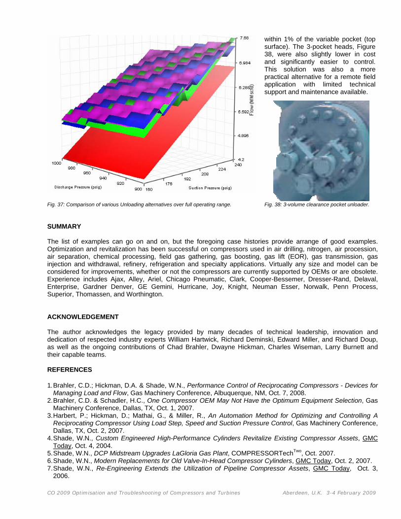
in3 (1.9, 3.7 and 5.6 L) fixed volume pockets, and an automatic variable volume pocket. In order to evaluate the alternative solutions, performance was compared at more than 1000 operating points within the operating range noted in Figure 37. The highest flow possible at each point was plotted for each case at each condition and the curves were overlayed for comparison. Over the range of 160 to 240 psig (11.0 to 15.5 bar) suction and 900 to 1000 psig (62.1 to 69.0 bar) discharge, the highest average flow was possible with the automatic variable volume pocket, however, the 3-volume pocket (the 2nd from the top surface in Figure 37) provided average flow that was
CO 2009 Optimisation and Troubleshooting of Compressors and Turbines Aberdeen, U.K. 3-4 February 2009
within 1% of the variable pocket (top surface). The 3-pocket heads, Figure 38, were also slightly lower in cost and significantly easier to control. This solution was also a more practical alternative for a remote field application with limited technical support and maintenance available.
Fig. 37: Comparison of various Unloading alternatives over full operating range. Fig. 38: 3-volume clearance pocket unloader. SUMMARY The list of examples can go on and on, but the foregoing case histories provide arrange of good examples. Optimization and revitalization has been successful on compressors used in air drilling, nitrogen, air procession, air separation, chemical processing, field gas gathering, gas boosting, gas lift (EOR), gas transmission, gas injection and withdrawal, refinery, refrigeration and specialty applications. Virtually any size and model can be considered for improvements, whether or not the compressors are currently supported by OEMs or are obsolete. Experience includes Ajax, Alley, Ariel, Chicago Pneumatic, Clark, Cooper-Bessemer, Dresser-Rand, Delaval, Enterprise, Gardner Denver, GE Gemini, Hurricane, Joy, Knight, Neuman Esser, Norwalk, Penn Process, Superior, Thomassen, and Worthington. ACKNOWLEDGEMENT The author acknowledges the legacy provided by many decades of technical leadership, innovation and dedication of respected industry experts William Hartwick, Richard Deminski, Edward Miller, and Richard Doup, as well as the ongoing contributions of Chad Brahler, Dwayne Hickman, Charles Wiseman, Larry Burnett and their capable teams. REFERENCES 1. Brahler, C.D.; Hickman, D.A. & Shade, W.N., Performance Control of Reciprocating Compressors - Devices for
Managing Load and Flow, Gas Machinery Conference, Albuquerque, NM, Oct. 7, 2008. 2. Brahler, C.D. & Schadler, H.C., One Compressor OEM May Not Have the Optimum Equipment Selection, Gas
Machinery Conference, Dallas, TX, Oct. 1, 2007. 3. Harbert, P.; Hickman, D.; Mathai, G., & Miller, R., An Automation Method for Optimizing and Controlling A
Reciprocating Compressor Using Load Step, Speed and Suction Pressure Control, Gas Machinery Conference, Dallas, TX, Oct. 2, 2007.
4. Shade, W.N., Custom Engineered High-Performance Cylinders Revitalize Existing Compressor Assets, GMC Today, Oct. 4, 2004.
5. Shade, W.N., DCP Midstream Upgrades LaGloria Gas Plant, COMPRESSORTechTwo, Oct. 2007. 6. Shade, W.N., Modern Replacements for Old Valve-In-Head Compressor Cylinders, GMC Today, Oct. 2, 2007. 7. Shade, W.N., Re-Engineering Extends the Utilization of Pipeline Compressor Assets, GMC Today, Oct. 3,
2006.


![Advanced Reciprocating Compression Technology [SWRI-DOE]](https://img.pdfslide.us/doc/110x75/55cf9787550346d033922507/advanced-reciprocating-compression-technology-swri-doe.jpg)

