Embed Size (px)
Citation preview
OPTIMISATION OF PULVERISED COAL COMBUSTION BY
MEANS OF CFD/CTA MODELLING
by
Risto V. FILKOSKI, Ilija J. PETROVSKI, and Piotr KARAS
Original scientific paperUDC: 662.62:519.876.5
BIBLID: 0354-9836, 10 (2006), 3, 161-179
The ob jec tive of the work pre sented in this pa per was to ap ply a method for han -dling two-phase re act ing flow for pre dic tion of pul ver ised coal com bus tion inlarge-scale boiler fur nace and to as sess the abil ity of the model to pre dict ex ist -ing power plant data. The pa per pres ents the prin ci pal steps and re sults of thenu mer i cal mod el ling of power boiler fur nace with tan gen tial dis po si tion of theburn ers. The com pu ta tional fluid dy nam ics/com pu ta tional ther mal anal y sis(CFD/CTA) ap proach is uti lised for cre ation of a three-di men sional model of the boiler fur nace, in clud ing the platen superheater in the up per part of the fur nace.Stan dard k-e model is em ployed for de scrip tion of the tur bu lent flow. Coal com -bus tion is mod elled by the mix ture frac tion/prob a bil ity den sity func tion ap -proach for the re ac tion chem is try, with equi lib rium as sump tion ap plied for de -scrip tion of the sys tem chem is try. Ra di a tion heat trans fer is com puted by meansof the sim pli fied P-N model, based on the ex pan sion of the ra di a tion in ten sityinto an or thogo nal se ries of spher i cal har mon ics.Some dis tinc tive re sults re gard ing the ex am ined boiler per for mance in ca pac ityrange be tween 65 and 95% are pre sented graph i cally. Com par ing the sim u la -tion pre dic tions and avail able site mea sure ments con cern ing tem per a ture, heatflux and com bus tion ef fi ciency, a con clu sion can be drawn that the model pro -duces re al is tic in sight into the fur nace pro cesses. Qual i ta tive agree ment in di -cates reasonability of the cal cu la tions and val i dates the em ployed sub-mod els.Af ter the val i da tion and ver i fi ca tion of the model it was used to check the com -bus tion ef fi ciency as a func tion of coal dust sieve char ac ter is tics, as well as theim pact of burn ers mod i fi ca tion with in tro duc tion of over fire air ports to the ap -pear ance of in com plete com bus tion, in clud ing CO con cen tra tion, as well as tothe NOx con cen tra tion.The de scribed case and other ex pe ri ences with CFD/CTA stress the ad van tagesof nu mer i cal mod el ling and sim u la tion over a purely field data study, such as theabil ity to quickly ana lyse a va ri ety of de sign op tions with out mod i fy ing the ob ject and the avail abil ity of sig nif i cantly more data to in ter pret the re sults.
Key words: CFD mod el ling, pul ver ised coal-fired boiler, com bus tion, ther -mal ra di a tion, heat trans fer, fur nace
Introduction
Ef fi cient use of pul ver ised coal in boil ers with tan gen tial burn ers sys tem is cru -cial to the power gen er a tion in the most South east ern Eu ro pean coun tries, which was the
161
main mo ti va tion for un der tak ing this re search. Cur rent revitalisation and mod erni sa tionof pul ver ised coal-fired boil ers mainly con cerns mod i fi ca tion of fur naces, res to ra tion ofthe mill ing sys tem, in stal la tion of low-NOx burn ers and over fire air (OFA) ports. Pricecom pe ti tion and emis sion lim its are forc ing the power plant own ers and op er a tors to im -prove the ef fi ciency and clean li ness of the com bus tion sys tems. In most cases, the mod i -fi ca tions are so com plex that their im pact on boiler per for mance can not be pre dictedwith out proper state-of-the-art mod el ling tools. Also, by its na ture, the com bus tion pro -cess of pul ver ised coal in boiler fur nace is an ex am ple of very com plex tur bu lent flow,ac com pa nied by strong cou pling of mass, mo men tum and en ergy in two phases.
Nu mer i cal sim u la tion tech niques through the last de cades have grown from be -ing prom is ing, mainly sci en tific tool, to a ba sic tech nol ogy, un avoid able in en gi neer ingprac tice. Sim u la tions made with proper nu mer i cal mod els us ing the com pu ta tional fluiddy nam ics and com pu ta tional ther mal anal y sis (CFD/CTA) of fer great po ten tial in ana lys -ing, de sign ing, retro fit ting and op ti mis ing per for mances of fos sil-fuel power sys tems.Such ap proach en ables en gi neers and re search ers to vir tu ally make de sign changes anddraw con clu sions re gard ing pos si ble con se quences. Com pared with other com pu ta tionalmeth ods, CFD/CTA mod el ling pro vides re search ers with de tailed in sight into the per for -mance char ac ter is tics of the in ves ti gated ob ject, giv ing better and more-ac cu rate rep re -sen ta tions of com bus tion sys tem's ge om e try, phys ics and chem is try at af ford able cost.Thus, it is be com ing a very ef fi cient tool in ef forts to meet strict com bus tion sys tem’s op -er a tion and per for mance goals.
Three-di men sional mod els of in dus trial and util ity scale com bus tion sys tems, in -clud ing mod els of tan gen tially fired fur naces, have been de vel oped and suc cess fully ap pliedfor years now [1-13]. Such mod els are of ten sim i lar to each other in many ways and the ma -jor ity use vari a tions of the SIMPLE al go rithm for cou pling of ve loc ity and pres sure and thek-e gas tur bu lence model, or some de riv a tives, like RNG k-e model [4], or k-e-kp two-phasetur bu lence model [10]. Gas phase con ser va tion equa tions are mostly time-av er aged andtwo-phase flow, as the one oc cur ring in pul ver ised coal boil ers, is usu ally de scribed byEulerian-Lagrangian ap proach and PSI-CELL method for tak ing into ac count the in flu encebe tween phases, with some ex cep tions us ing Eulerian-Eulerian ap proach or two-fluid tra jec -tory model. Most of the com bus tion submodels given in [3, 4, 7, 9-11, 13] sep a rately treatpar ti cle devolatilisation, char ox i da tion and ad di tional gas phase re ac tions. Ther mal ra di a -tion is mod elled by means of var i ous ap proaches, like dis crete trans fer method, dis crete or di -nates method [7, 10, 11], six-fluxes method [9], Monte Carlo method [4], or so-called P-Nmodel [14], as in this pa per. Com mer cial CFD codes are ap plied suc cess fully [2, 3, 11-13],but also re search ef forts are given world wide to mod els spe cially de vel oped for sim u la tionof fur naces. It should be em pha sized that a com pre hen sive model of the fur nace pro cessesmust bal ance sub-model so phis ti ca tion with com pu ta tional prac ti cal ity.
Boiler design data and operating conditions
The util ity boiler OB-380, ana lysed as a test case in this study [15, 16], de signedand man u fac tured by RAFAKO S. A., Raciborz, Po land, is lo cated at the 120 MW ther -
162
THERMAL SCIENCE: Vol. 10 (2006), No. 3, pp. 161-179
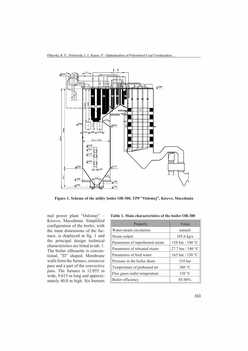
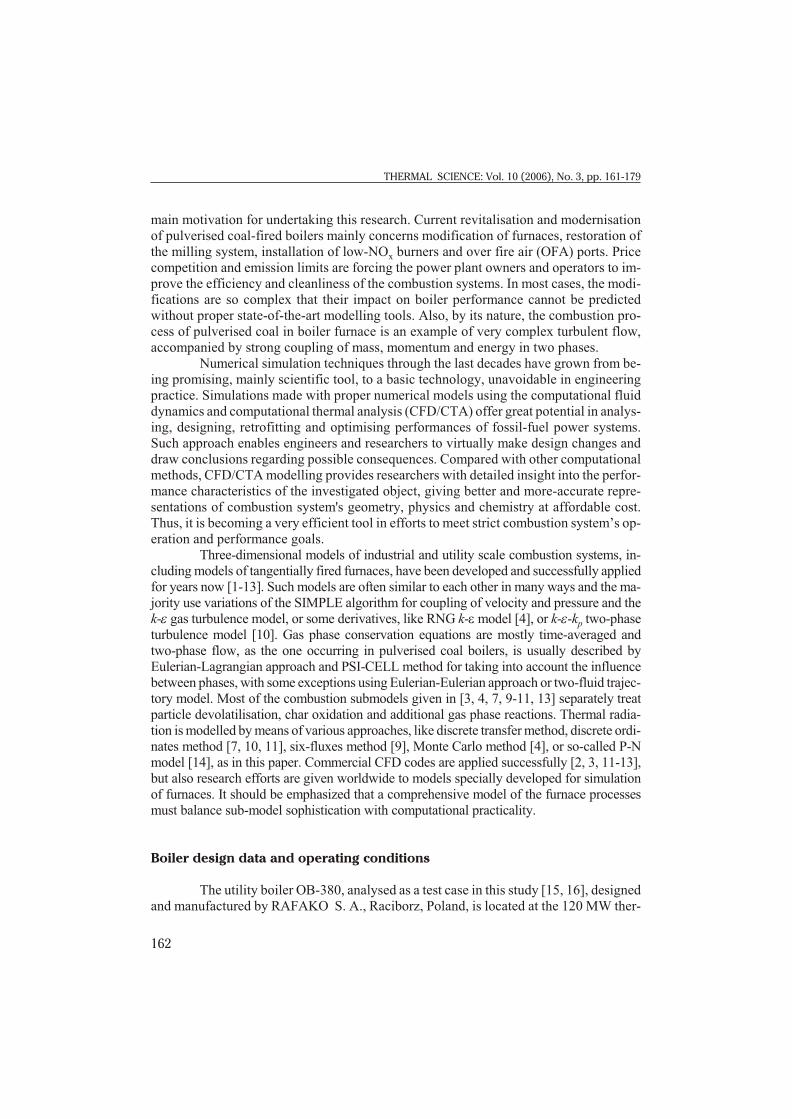
mal power plant “Oslomej” –Kicevo, Mac e do nia. Sim pli fiedcon fig u ra tion of the boiler, withthe main di men sions of the fur -nace, is dis played in fig. 1 andthe prin ci pal de sign tech ni calchar ac ter is tics are listed in tab. 1. The boiler sil hou ette is con ven -tional, ”P” shaped. Mem branewalls form the fur nace, cross over pass and a part of the con vec tivepass. The fur nace is 12.055 mwide, 9.615 m long and ap prox i -mately 40.0 m high. Six burn ers
163
Filkoski, R. V., Petrovski, I. J., Karas, P.: Optimisation of Pulverised Coal Combustion ...
Figure 1. Scheme of the utility boiler OB-380, TPP ”Oslomej”, Kicevo, Macedonia
Table 1. Main characteristics of the boiler OB-380
Prop erty Value
Water-steam circulation nat u ral
Steam output 105.6 kg/s
Parameters of superheated steam 138 bar / 540 °C
Parameters of reheated steam 27.7 bar / 540 °C
Parameters of feed water 165 bar / 230 °C
Pressure in the boiler drum 154 bar
Temperature of preheated air 260 °C
Flue gases outlet temperature 150 °C
Boiler efficiency 85-88%

for pul ver ised coal are ar ranged in such man ner, as shown in fig. 2, to gen er ate swirl ingflow of gas-solid mix ture. Two of the burn ers are in stalled on the front, two on the backfur nace wall and one on each side wall. The boiler has al ready ex panded its de sign op er a -tional life time, work ing very of ten at max i mum ca pac ity.
The boiler is fired with low-grade coal, lig nite from the near-by coal mine, withhuge con tent of bal last ma te ri als and with cal o rific value vary ing in broad range be tween6500-8800 kJ/kg. Typ i cal av er age prox i mate and ul ti mate ana lyse of the coal are given in tab. 2. Av er age coal con sump tion of the boiler op er ated at full load is 45-52 kg/s, whileflue gases out flow in that case is ap prox i mately 160-200 m3/s.
The sim u la tions in this studyare per formed in ac cor dance tothe pres ent sta tus of the boiler,which means, with the ex ist ingburner sys tem dis po si tion. Three ba sic cases of op er at ing modesare sub ject of con sid er ation inthe ar ti cle: work ing mode R1cor re spond ing to 83% boilerload (100 MW elec tri cal out put)with five burn ers in ser vice,
164
THERMAL SCIENCE: Vol. 10 (2006), No. 3, pp. 161-179
Figure 2. Position of the burners in the furnace and burner vertical cross-section
Table 2. Proximate and ultimate analysis of theOslomej lignite (average values)
Prox i mate anal y sis [%] Ul ti mate anal y sis [%]
Char 29.15 C 23.45
Volatiles 21.35 H 2.11
Cfix 13.38 O 7.50
Ash 15.77 N 1.10
Moisture 49.50 S 0.57

modes R2 and R3 con ducted on the ba sis of al most full load (115 MW elec tri cal out put)and modes R4 and R5 that cor re spond to 67% load. Val ues of the boiler pa ram e ters andop er at ing con di tions at modes R1 to R5 are pre sented in tab. 3 [15].
Table 3. Boiler parameters at three different operating regimes [15]
Property Mode R1 Mode R2 Mode R3 Mode R4 Mode R5
Electrical output [MW] 99.5 113.4 114.0 80.2 80.8
Heat output [MW] 269.5 300.7 312.3 215.5 214.5
Steam production [kg/s] 86.8 97.5 95.0 65.3 68.3
Fuel consumption [kg/s] 36.1 42.4 43.3 30.8 30.6
Boiler efficiency [%] 87.45 86.41 87.79 84.44 83.85
Temperature of flue gases at boiler outlet [°C] 156 166 142 147 161
CO2/O2 in flue gases at the boiler outlet [%] 10.94/8.68 12.38/6.95 11.95/7.35 8.41/10.94 8.34/11.02
Temperature of preheated air [°C] 206 215 185 195 219
Excess air coefficient ahead of the air heaters 1.415 1.295 1.345 1.965 1.985
Burner out of service No. 4 No. 3 No. 3 No. 3 No. 3
Description of the applied model
CFD mod el ling con sists of so lu tion of gov ern ing equa tions for fluid flow, heatand mass trans fer, ra di a tion, chem i cal re ac tions, in clud ing com bus tion and other mod el -ling equa tions. The equa tions are solved at sev eral hun dreds of thou sands dis crete pointsof nu mer i cal grid, in the pre vi ously de fined com pu ta tional do main. When the pro cess in -volves flow of more than one phase, i. e. gasand solid par ti cles, one ap proach is to modelthe pro cess by solv ing a set of Navier-Stokesequa tions for the ma jor phase, and to treat themi nor phase as a set of dis crete par ti cles ordrop lets, which are tracked in di vid u ally. Thisap proach, Eulerian for gas eous and Lagran-gian for dis crete phase, is ap pro pri ate whenthe vol ume frac tion of the dis crete phase islow, such as in the case of pul ver ised coalcom bus tion and, con se quently, it is used inthis re search.
Gen eral struc ture of the case set-upand so lu tion us ing the CFD/CTA tech nique ispre sented in fig. 3 [17]. Gam bit pre-pro ces soris used for ge om e try cre ation and mesh gen er -
165
Filkoski, R. V., Petrovski, I. J., Karas, P.: Optimisation of Pulverised Coal Combustion ...
Figure 3. Structure of the case set-up and solution with the CFD technique in thecase of Fluent CFD package [17]

a tion, which is pre sented in fig. 4. Nu mer i cal mesh of 124839 fi nite vol ume cells, 375573 faces, and 125880 nodes is em ployed dur ing the in ves ti ga tion. Some pre vi ous CFD sim u -la tions of this boiler unit, con ducted with much denser nu mer i cal mesh, have given sim i -lar re sults to those pre sented in this ar ti cle, but the CPU de mand was much higher. TheCFD soft ware Flu ent and prePDF pre-pro ces sor are em ployed for de scrip tion of tur bu -lent fluid flow, devolatilization, coal com bus tion, gas phase chem i cal re ac tions, and heattrans fer. The sim u la tions are per formed for steady-state op er at ing con di tions, in a 3-Ddomain representing the full volume of the boiler furnace.
Tur bu lent mix ing in the fur nace was taken into ac count with the stan dardsteady k-e model. Com mon val ues of the con stants are used in the trans port equa tions:sk = 1.0, se = 1.3, C1e = 1.44, and C2e = 1.92. Cou pling of the con ti nu ity and mo men tum
166
THERMAL SCIENCE: Vol. 10 (2006), No. 3, pp. 161-179
Figure 4. Boiler furnace geometry: (a) feature, (b) finite-volume mesh, and (c) superheaterzone (color image see on our web site)
equa tions is achieved by the SIMPLEC al go rithm. Sto chas tic track ing model is used inthe cal cu la tions to take the ef fects of tur bu lence on the par ti cle tra jec to ries into ac -count. Mass flow rate, tem per a ture, and mix ture frac tion is as signed at coal and air in -lets, while out flow is pre scribed at the re cir cu lat ing holes and at the fur nace exit,which, in this test case is lo cated af ter the platen superheater. The superheater is mod -elled with para met ric heat exchanger model to ac count for the heat ab sorp tion and pres -sure loss [15, 17]. For that pur pose, a sep a rate fluid zone is de fined to rep re sent thesuperheater core (fig. 4c), which is sub di vided into mac ro scopic cells (“macro cells“)along the cool ant path [15]. The cool ant in let tem per a ture to each macro cell is com -puted and then sub se quently used to com pute the heat re jec tion from each macro cell.This ap proach pro vides a re al is tic heat re jec tion dis tri bu tion over the heat exchangercore. Soot for ma tion and emis sion of pol lut ants, such as NOx, is taken into con sid er -ation in the cur rent steps of the in ves ti ga tion.
Nu mer i cal sim u la tion of pul ver ised coal com bus tion in volves mod el ling of con -tin u ous gas phase flow field and its in ter ac tion with a dis crete phase of coal par ti cles,which have non-uni form size dis tri bu tion, with di am e ters rang ing from 0 to 1000 mm.The polydisperse par ti cle size dis tri bu tion is as sumed to fit the Rosin-Rammler equa tionwith a mean di am e ter dpm = 90-120 mm and a spread pa ram e ter of 3.5.
The coal par ti cles, car ried by air-gas mix ture, devolatilise and un dergo charcom bus tion, cre at ing a source of fuel for re ac tion in the gas phase. The coal par ti cle en -ergy bal ance is used to cal cu late the par ti cle tem per a ture and to de scribe the coal evo lu -tion. In this test case, two-competiting-ki netic-rates model is se lected as a devolatilisa-tion model. Com bus tion of pul ver ised coal is mod elled as non-pre mixed ki net ics/dif fu -sion-lim ited pro cess with the mix ture-frac tion/prob a bil ity den sity func tion (PDF) ap -proach for the re ac tion chem is try [17, 18]. Full equi lib rium chem is try is se lected as achem is try model and the tur bu lence-chem is try in ter ac tion is mod elled with a b prob a bil -ity den sity func tion. It is as sumed that the PDF mix ture con sists of 16 vol u met ric spe cies: C(S), C, H, O, N, O2, N2, CO2, H2O, H2O(L), CH4, H2, CO, OH, NO, and HCN. Coal par -ti cle tra jec tory data, coal devolatilisation and com bus tion pa ram e ters used in the modelare given in tabs. 4 and 5. Recirculation of the flue gases through holes in the up per partof the fur nace (fig. 1) is in cluded in the com pu ta tions with a co ef fi cient rg = 0.25-0.31,de pend ing on the work ing mode.
One of the im por tant is sues in the case of coal com bus tion mod el ing is in clu sionof the ef fect of dis crete phase pres ence on the ra di a tion ab sorp tion co ef fi cient. The ba sic
ra di a tive trans fer equa tion for an ab sorb ing,emit ting and scat ter ing me dium with con tri bu -tion of the par tic u late phase, at po si tion r in di -rec tion s is:
d
d
pp
I
sa a s I
anT
E I
p p( )
( ) ( )
( , )
r, sr, s
r s
+ + + =
= + + ¢24
4
s
p p
sF( )s s×
p
¢ ¢ò dW0
4
(1)
167
Filkoski, R. V., Petrovski, I. J., Karas, P.: Optimisation of Pulverised Coal Combustion ...
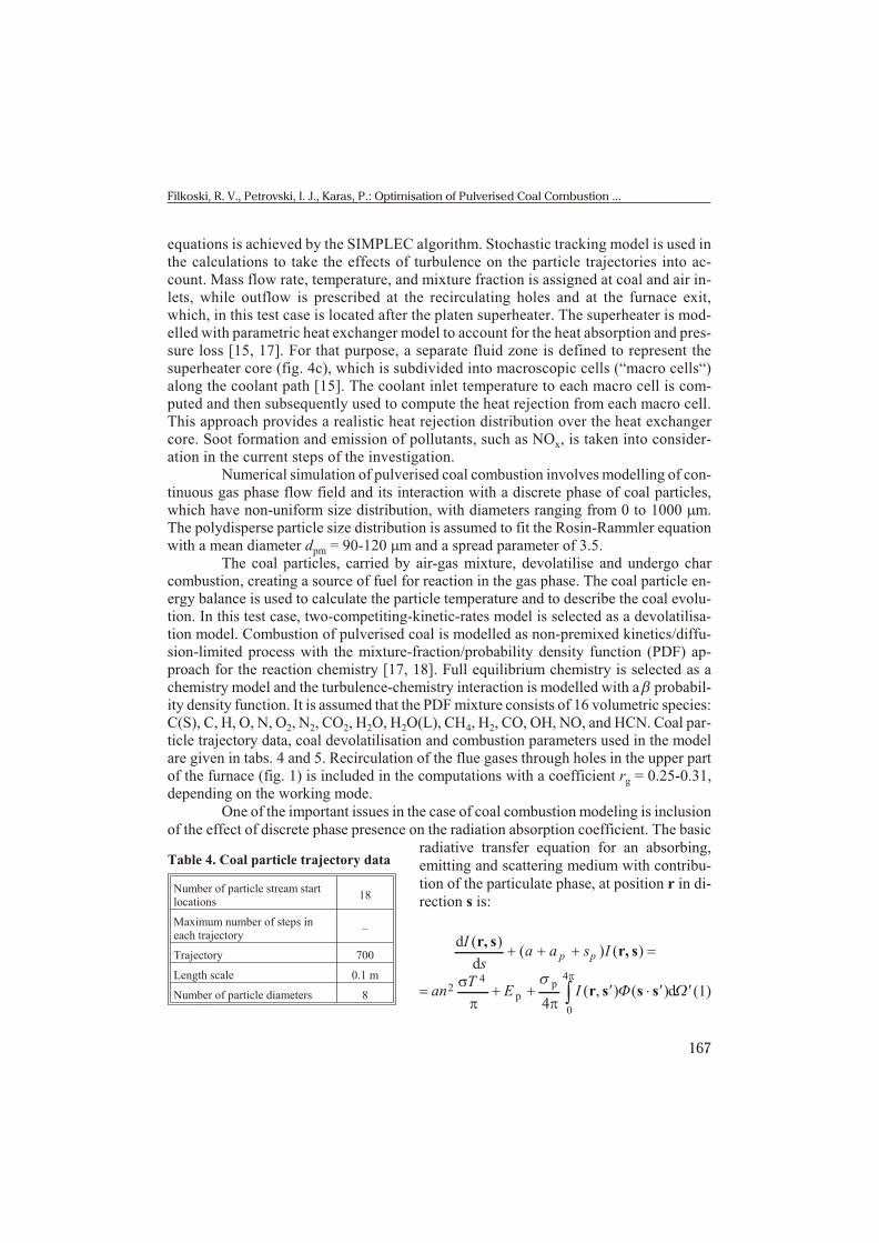
Table 4. Coal particle trajectory data
Number of particle stream startlocations
18
Maximum number of steps ineach trajectory
–
Trajectory 700
Length scale 0.1 m
Number of particle diameters 8
where I is total radiation intensity, which depends on position r and direction s, s is pathlength, ap is the equivalent absorption coefficient due to the presence of particulates, sp is equivalent particle scattering factor, Ep is the equivalent particle emissivity, a is absor-ption coefficient, n is refractive index, s is Stefan-Boltzmann constant, T is local absolute temperature, s' is scattering direction vector, F is phase function and W' is solid angle.The product (a + ss) s is optical thickness or opacity of the medium.
In this work, ra di a tion is taken into ac count in the heat trans fer sim u la tionsthrough the so-called P-1 model [14, 17], based on ex pan sion of the ra di a tion in ten sity Iinto an or thogo nal se ries of spher i cal har mon ics [14, 19, 20]. If only four terms in the se -ries are used, the fol low ing equa tion is ob tained for the ra di a tion flux:
qa C
Grs s
= -+ -
Ñ1
3( )s s
(2)
where G is in ci dent ra di a tion, ss is scat ter ing co ef fi cient, and C is lin ear-anisotropicphase func tion co ef fi cient. Vari able ab sorp tion co ef fi cient a is com puted by theweighted-sum-of-gray-gases model (WSGGM) [17, 20-22].
The P-1 model has sev eral ad van tages over other ra di a tion mod els, treat ing thera di a tive trans fer equa tion (1) as an easy-to-solve dif fu sion equa tion. Also, it is rel a tively sim ple, it can be eas ily ap plied to com pli cated ge om e tries and it works rea son ably wellfor com bus tion ap pli ca tions where the op ti cal thick ness is large. The par ti cle emissivity,re flec tivity, and scat ter ing can be ef fec tively in cluded in the cal cu la tion of the radiationheat trans fer.
The trans port equa tion for G is:
168
THERMAL SCIENCE: Vol. 10 (2006), No. 3, pp. 161-179
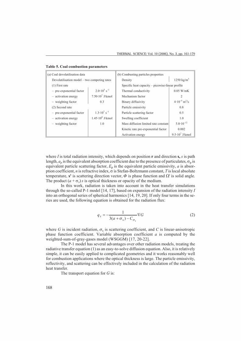
Table 5. Coal combustion parameters
(a) Coal devolatilisation data (b) Combusting particles properties
Devolatilisation model – two competing rates Density 1250 kg/m3
(1) First rate Specific heat capacity – picewise-linear profile
– pre-exponential factor 2.0×10⁵ s-1 Thermal conductivity 0.05 W/mK
– activation energy 7.50×10⁷ J/kmol Mechanism factor 2
– weighting factor 0.3 Binary diffusivity 4×10⁻⁵ m2/s
(2) Second rate Particle emissivity 0.8
– pre-exponential factor 1.3×10⁷ s-1 Particle scattering factor 0.5
– activation energy 1.45×10⁸ J/kmol Swelling coefficient 1.0
– weighting factor 1.0 Mass diffusion limited rate constant 5.0×10⁻¹²
Kinetic rate pre-exponential factor 0.002
Activation energy 9.5×10⁷ J/kmol

Ñ Ñ +æ
èç
ö
ø÷ - + =( ( )G G +) 4 pp a
TE a a Gp
s
p
40 (3)
in which the parameter G is defined through the equivalent absorption coefficient ap andthe equivalent particle scattering factor sp:
G =+ +
1
3( )a a p s p
(4)
With sub sti tu tion qr = -GÑG in eq. (3) the fol low ing ex pres sion is ob tained for-Ñqr:
-Ñ = - +æ
èç
ö
ø÷ + +q a
TE a a Gpr p4
4p
s
p( ) (5)
which can be directly included into the energy equation to account for heat sources due to radiation.
The flux of the in ci dent ra di a tion at wall qrw is de ter mined with the ex pres sion:
q T Grww
ww w= -
--
e
e2 24 4
( )( )s (6)
where ew is wall emissivity, Tw is wall temperature, and Gw is incident wall radiation. The wall emissivity in this test case is specified in the range 0.65 to 0.8 at the furnace wallsand 1.0 at the furnace bottom and exit. Sidewall temperature is calculated on a basis of the near-wall heat transfer conditions.
Model evaluation and discussion
The 3-D CFD mod el ling ap proach of the com bus tion sys tems pro vides re search -ers with a more de tailed un der stand ing of the per for mance char ac ter is tics of the in ves ti -gated ob ject. Fur ther more, it is be com ing a very ef fi cient tool in ef forts to meet strictboiler's op er a tion and per for mance goals. The main re sults of the per formed CFD sim u la -tion con cern ing the OB-380 boiler con sist of flow fields, ve loc ity vec tors, par ti cles pathlines, tem per a ture con tours, heat flux pro files to the fur nace walls, con tours of O2, CO2
and other spe cies con cen tra tions, as well as data on other im por tant vari ables. Some typ i -cal re sults are dis played in the fol low ing fig ures. Flow field shown through gas phase ve -loc ity vec tors in two ver ti cal fur nace cen tral in ter sec tions is pre sented in fig. 5. Dis tur -bances of the gen eral up ward flow can be seen in the vi cin ity of the burn ers. Theexistence of some regions with reversed flow in the furnace is predicted correctly.
169
Filkoski, R. V., Petrovski, I. J., Karas, P.: Optimisation of Pulverised Coal Combustion ...
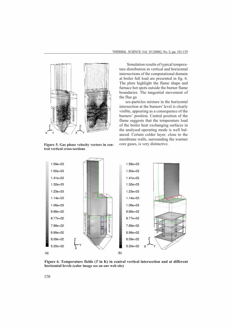
Sim u la tion re sults of typ i cal tem per a -ture dis tri bu tion in ver ti cal and hor i zon talin ter sec tions of the com pu ta tional do main at boiler full load are pre sented in fig. 6.The plots high light the flame shape andfur nace hot spots out side the burner flamebound aries. The tan gen tial move ment ofthe flue ga
ses-par ti cles mix ture in the hor i zon talin ter sec tion at the burn ers' level is clearlyvis i ble, ap pear ing as a con se quence of theburn ers’ po si tion. Cen tral po si tion of theflame sug gests that the tem per a ture loadof the boiler heat ex chang ing sur faces inthe ana lysed op er at ing mode is well bal -anced. Cer tain colder layer, close to themem brane walls, sur round ing the warmercore gases, is very dis tinc tive.
170
THERMAL SCIENCE: Vol. 10 (2006), No. 3, pp. 161-179
Figure 6. Temperature fields (T in K) in central vertical intersection and at differenthorizontal levels (color image see on our web site)
Fig ure 5. Gas phase ve loc ity vec tors in cen -tral ver ti cal cross-sec tions
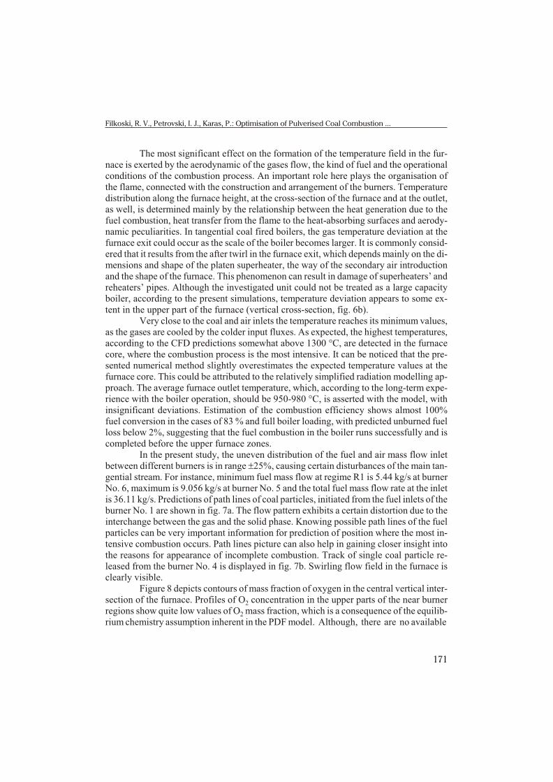
The most sig nif i cant ef fect on the for ma tion of the tem per a ture field in the fur -nace is ex erted by the aero dy namic of the gases flow, the kind of fuel and the op er a tionalcon di tions of the com bus tion pro cess. An im por tant role here plays the or gani sa tion ofthe flame, con nected with the con struc tion and ar range ment of the burn ers. Tem per a turedis tri bu tion along the fur nace height, at the cross-sec tion of the fur nace and at the out let,as well, is de ter mined mainly by the re la tion ship be tween the heat gen er a tion due to thefuel com bus tion, heat trans fer from the flame to the heat-ab sorb ing sur faces and aero dy -namic pe cu liar i ties. In tan gen tial coal fired boil ers, the gas tem per a ture de vi a tion at thefur nace exit could oc cur as the scale of the boiler be comes larger. It is com monly con sid -ered that it re sults from the af ter twirl in the fur nace exit, which de pends mainly on the di -men sions and shape of the platen superheater, the way of the sec ond ary air in tro duc tionand the shape of the fur nace. This phe nom e non can re sult in dam age of super heat ers’ andreheaters’ pipes. Al though the in ves ti gated unit could not be treated as a large ca pac ityboiler, ac cord ing to the pres ent sim u la tions, tem per a ture de vi a tion ap pears to some ex -tent in the up per part of the fur nace (ver ti cal cross-sec tion, fig. 6b).
Very close to the coal and air in lets the tem per a ture reaches its min i mum val ues,as the gases are cooled by the colder in put fluxes. As ex pected, the high est tem per a tures,ac cord ing to the CFD pre dic tions some what above 1300 °C, are de tected in the fur nacecore, where the com bus tion pro cess is the most in ten sive. It can be no ticed that the pre -sented nu mer i cal method slightly over es ti mates the ex pected tem per a ture val ues at thefur nace core. This could be at trib uted to the rel a tively sim pli fied ra di a tion mod el ling ap -proach. The av er age fur nace out let tem per a ture, which, ac cord ing to the long-term ex pe -ri ence with the boiler op er a tion, should be 950-980 °C, is as serted with the model, within sig nif i cant de vi a tions. Es ti ma tion of the com bus tion ef fi ciency shows al most 100%fuel con ver sion in the cases of 83 % and full boiler load ing, with pre dicted un burned fuelloss be low 2%, sug gest ing that the fuel com bus tion in the boiler runs suc cess fully and iscom pleted be fore the up per fur nace zones.
In the pres ent study, the un even dis tri bu tion of the fuel and air mass flow in letbe tween dif fer ent burn ers is in range ±25%, caus ing cer tain dis tur bances of the main tan -gen tial stream. For in stance, min i mum fuel mass flow at re gime R1 is 5.44 kg/s at burnerNo. 6, max i mum is 9.056 kg/s at burner No. 5 and the to tal fuel mass flow rate at the in letis 36.11 kg/s. Pre dic tions of path lines of coal par ti cles, ini ti ated from the fuel in lets of the burner No. 1 are shown in fig. 7a. The flow pat tern ex hib its a cer tain dis tor tion due to thein ter change be tween the gas and the solid phase. Know ing pos si ble path lines of the fuelpar ti cles can be very im por tant in for ma tion for pre dic tion of po si tion where the most in -ten sive com bus tion oc curs. Path lines pic ture can also help in gain ing closer in sight intothe rea sons for ap pear ance of in com plete com bus tion. Track of sin gle coal par ti cle re -leased from the burner No. 4 is dis played in fig. 7b. Swirl ing flow field in the fur nace isclearly vis i ble.
Fig ure 8 de picts con tours of mass frac tion of ox y gen in the cen tral ver ti cal in ter -sec tion of the fur nace. Pro files of O2 con cen tra tion in the up per parts of the near burnerre gions show quite low val ues of O2 mass frac tion, which is a con se quence of the equi lib -rium chem is try as sump tion in her ent in the PDF model. Al though, there are no avail able
171
Filkoski, R. V., Petrovski, I. J., Karas, P.: Optimisation of Pulverised Coal Combustion ...

172
THERMAL SCIENCE: Vol. 10 (2006), No. 3, pp. 161-179
Figure 7. (a) Path lines of coal particles streams released from the burner No. 1, and (b)traces of particles released from the burner No. 4 (color image see on our web site)
Figure 8. Contours of oxygen massfraction at the furnace central cross-section (color image see on our web site)
Figure 9. Contours of NO mass fraction at thefurnace central cross-section and at the furnace exit(color image see on our web site)

site operation records regarding the O2 mass fraction at the furnace outlet, comparison tothe values of excess air coefficient ahead of the air heaters (tab. 3) shows that thenumerical results are close to the real values.
Pres ent sim u la tions in clude as sess ment of the NOx for ma tion and re duc tion dur -ing the com bus tion pro cess. An ex am ple of the re sults con cern ing this is sue is pre sentedin fig. 9. Since the used fuel is low cal o rific lig nite and, con se quently, fur nace tem per a -tures are mod er ate, ap pear ance of ther mal NOx is ir rel e vant and the to tal NOx emis sion,con sist ing mostly of fuel NOx, is not very high.
Tem per a ture and heat flux to the walls in the fur nace are mea sured through 31mea sure ment ports at four lev els: 13.9, 20.4, 23.0, and 26.4 m (the bot tom of the fur nacefun nel is lo cated ap prox i mately at el e va tion of 6.5 m), with as pi ra tion py rom e ter,non-cooled tem per a ture probe and dig i tal op ti cal py rom e ter.
Typ i cal pro files of mea sured and com puted tem per a tures from the front fur nacewall in di rec tion to ward the cen tre, at el e va tion 26.4 m, are shown in fig. 10 [15]. Rel a -tively well con for mity be tween the CFD pre dic tions and avail able field data can be no -ticed at the right side, but the dis crep ancy is con sid er able on the left side of the cen tralfur nace cross-sec tion. Pro files of mea sured and av er age area-weighted tem per a turealong the fur nace height at modes R1 to R5 are dis played in fig. 11 [15]. Ap pear ance of
173
Filkoski, R. V., Petrovski, I. J., Karas, P.: Optimisation of Pulverised Coal Combustion ...
Fig ure 10. Tem per a ture con tours at el e -va tion 26.4 m (approx. 20 m above thefur nace bot tom), mode R1: CFD-P15,CFD-P22 – model, 1.075 m from the leftand right side wall, re spec tively; M-P15,M-P22 – mea sure ments, 1.075 m fromthe left and right side wall
Fig ure 11. Area-weighted av er age tem -per a ture along the fur nace height: R1 toR5 – mea sure ments; CFD-R1 to CFD-R5– model results

tem per a ture peaks at ap prox i mate height of 18 m can not be ver i fied, nei ther de nied withthe avail able mea sure ments. Fig ure 12 de picts area-weighted av er age heat flux to thewalls along the fur nace height, pre dicted with CFD and con fronted with mea sured heatfluxes [15]. Ac cord ing to the sim u la tions, max i mum lo cal heat flux val ues in the zone ofin ten sive com bus tion don’t ex ceed 120-150 kW/m2, which is in agree ment with rec om -men da tions for this type of boiler fur nace. It must be noted that the av er ag ing of the heatflux in this case is rel a tively rough, since the tan gen tial burn ers di rec tion causes un evenheat flux dis tri bu tion in hor i zon tal di rec tion of the fur nace walls at the burn ers level.Mea sure ments are con ducted at sev eral dif fer ent points on each level, and, for in stance,the max i mum heat flux value at el e va tion 13.9 m is reg is tered at left hand side and themin i mum at right and back sides.
A change of the av er age ther mal ef fi ciency of the fur nace walls along the boilerheight is given in fig. 13 [15]. In this di a gram, the re sults ob tained by the CFD sim u la -tions are con fronted to the val ues cal cu lated in di rectly on the ba sis of the heat flux andtem per a ture mea sure ments. For com par i son, the change of the ther mal ef fi ciency of thewalls ac cord ing to the Nor ma tive Method of the CKTI (ac cord ing to [22]) is presented inthe same figure.
Com bus tion ef fi ciency in the modes R1-R3, ac cord ing to the mea sure ments andCFD sim u la tions, is il lus trated with fig. 14 [15]. The vari a tion of the com bus tion ef fi -ciency as a func tion of coal sieve anal y sis is pre sented in fig. 15 [15, 16]. Re sults are ob -tained with the nu mer i cal model, ana lys ing cases when the coal dust mean di am e ter is dpm = 110 and 140 mm. The in flu ence of the better coal grind ing to the mini mi sa tion ofheat losses caused by in com plete com bus tion is ob vi ous.
174
THERMAL SCIENCE: Vol. 10 (2006), No. 3, pp. 161-179
Figure 12. Heat flux distribution along Figure 13. Average coefficient of thermal the furnace height efficiency of the furnace walls

Fig ure 16 il lus trates the im pact of in tro duc tion of OFA ports for sec ond ary air tothe con cen tra tion of NOx in the flue gases [15, 16]. Scheme in fig. 16a shows the pre -sumed po si tion of the OFA port above the burner. Pro files of mass frac tions of CO andNOx in the cen tral ver ti cal fur nace in ter sec tion in mode R1 with im ple mented OFA sys -tem for sec ond ary air are given in fig. 17. The con cen tra tions of both, CO and NOx, aresub stan tially lower than in the case with out OFA ports.
175
Filkoski, R. V., Petrovski, I. J., Karas, P.: Optimisation of Pulverised Coal Combustion ...
Figure 14. Combustion efficiency along Figure 15. Combustion efficiency as functionthe furnace in the modes R1, R2, and R3 of coal sieve char ac ter is tics at dpm = 110 and 140 mm
Figure 16. (a) Position of OFA port; (b) Concentration of NOx along the furnace height –mode R1 with and without OFA system implemented

Fi nally, fig. 18 is an il lus tra tive ex am ple of the tem per a ture pro file in the modeR1 with im ple mented OFA sys tem for sec ond ary air in tro duc tion. The tem per a ture in thein ter sec tion be hind the platen superheater is much evenly dis trib uted in the pre sumedcase when the OFA sys tem is im ple mented, com pared to the case pre sented in fig. 6b.The ve loc ity di rec tion is sup posed to be nor mal to the fur nace walls, which ad di tion allycon trib utes to the mini mi sa tion of tem per a ture de vi a tion.
176
THERMAL SCIENCE: Vol. 10 (2006), No. 3, pp. 161-179
Figure 17. Profiles of mass fractions of CO and NO in central vertical furnace intersection in the mode R1 with OFA system for secondary air implemented (color image see on our website)
Fig ure 18. Tem per a ture pro filein the in ter sec tion be hind theplaten superheater in the modeR1 with im ple mented OFA sys -tem for sec ond ary air (color im -age see on our web site)
The de scribed CFD method gives a pos si bil ity to in ves ti gate the op er a tion of the boiler in var i ous con di tions, with dif fer ent load, as well as with re dis tri bu tion of coal andair mass flow at the in lets, which would lead to cer tain changes of the flame po si tion andother pa ram e ters. The pro ce dure dis cussed in the ar ti cle and ap plied here to large boilerfur nace has wide band as ser tion ap pli ca bil ity. The jus ti fi ca tion for this re sides in the va ri -ety of pro cesses and phe nom ena, which the CFD has al ready been shown to be able tohan dle. Cur rent and fu ture work in this field is fo cused on fur ther sim u la tions of theboiler op er a tion with: var ied burn ers’ load ing, coal of var i ous size dis tri bu tion,over-fire-air sys tem im ple mented, cal cu la tions of NOx emis sion and pre dic tions of aero -dy nam ics and ther mal be hav iour of gas-sol ids mix ture in the near-burner re gion.
Conclusions
The pa per pres ents meth od ol ogy used to nu mer i cally model fur nace pro cessesof a tan gen tial pul ver ised coal-fired power boiler, based on com pu ta tional fluid dy nam -ics and com pu ta tional ther mal anal y sis. On a ba sis of com par i son with avail able site re -cords a con clu sion can be drawn that the model pro duces re al is tic in sight into the fur nacepro cesses. Val ues of tem per a ture and heat flux are in ex pected lim its, typ i cal for thisboiler type and for the coal used and, gen er ally, they fol low the trend line of mea sure -ments. The model slightly over es ti mates the tem per a ture val ues at the fur nace core, butrel a tively well de scribes the two-phase gas-solid flow field, mostly determined by thetangential disposition of the burners.
Sim u la tion re sults con cern ing the fur nace walls ther mal ef fi ciency and com bus -tion ef fi ciency also show good cor re spon dence with the plant data. Pre dic tions on COand NOx con cen tra tions, both with and with out OFA sys tem, could not be ver i fied withavail able field data, but the ob tained val ues are quite rea son able and in line with the pre -vi ous ex pe ri ence with sim i lar boiler de signs.
Nomenclature
a – absorption coefficient, [–]ap – equivalent absorption coefficient due to presence of particulates, [–]C – linear-anisotropic phase function coefficient, [–]C1e – constant in the k-e turbulence model, (= 1.44), [–]C2e – constant in the k-e turbulence model, (= 1.92), [–]dp – particle diameter, [m]Ep – equivalent particle emissivity, [–]G – incident radiation, [W/m2]Gw – incident wall radiation, [W/m2]I – total radiation intensity, [W/m2]k – turbulence kinetic energy, [m2/s2]n – refractive index, [–]qr – radiation flux, [W/m2]qrw – incident radiation flux at wall, [W/m2]
177
Filkoski, R. V., Petrovski, I. J., Karas, P.: Optimisation of Pulverised Coal Combustion ...

r – position vector, [–]rg – recirculating factor, [–]s – path length, [m]s – direction vector, [–]s' – scattering direction vector, [–]T – temperature, [K]Tw – wall temperature, [K]
Greek symbols
G – parameter defined through the equivalent absorption coefficient ap and the equivalent particle scattering factor sp, eq. (4)
e – turbulence kinetic energy dissipation rate, [m2/s3]ew – wall emissivity, [–]s – Stefan-Boltzmann constant, (= 5.672×10⁻⁸ W/m2K4)sk – kinetic energy constant in the transport equations, [–]sp – equivalent particle scattering factor, [–]ss – scattering coefficient, [–]se – kinetic energy dissipation rate constant in the transport equations, [–]F – phase function, [–]W' – solid angle, [sterad]
References
[1] Fiveland, A. W., Wessel, A. R., Nu mer i cal Model for Pre dict ing Per for mance of Three-Di -men sional Pul ver ized-Fuel Fired Fur naces, Journal of Eng. for Gas Tur bines and Power, 110 (1988), 1, pp. 117-126
[2] Risio, B., Schnell, U., New Nu mer i cal Meth ods for the De scrip tion of Phe nom ena Oc cur ringin Tan gen tially Fired Pul ver ised Coal Boil ers, EU Pro ject Per for mance Pre dic tion in Ad -vanced Coal Fired Boil ers, Con tract No JOF3-CT95-0005, Stuttgart, Ger many, 1998
[3] Xu, M., Azevedo, J. L. T., Carvalho, M. G., Mod el ling of the Com bus tion Pro cess and NOx
Emis sion in a Util ity Boiler, Fuel, 79 (2000), 13, pp. 1611-1619[4] Fan, J., Qian, L., Ma, Y., Sun, P., Cen, K., Com pu ta tional Mod el ing of Pul ver ized Coal Com -
bus tion Pro cesses in Tan gen tially Fired Fur naces, Chem i cal En gi neer ing Jour nal, 81 (2001),pp. 261-270
[5] Jones, J. M., Pourkashanian, M., Wil liams, A., Chakraborty, R. K., Sykes, J., Laurence, D.,Mod el ling of Coal Com bus tion Pro cesses – a Re view of Pres ent Sta tus and Fu ture Needs,Pro ceed ings, 15th An nual In ter na tional Pitts burgh Coal Con fer ence, Pitts burgh, PA, USA,1998, pp. 1-20
[6] Eaton, A. M., Smoot, L. D., Hill, S. C., Eatough, C. N., Com po nents, For mu la tions, So lu -tions, Eval u a tion and Ap pli ca tion of Com pre hen sive Com bus tion Mod els, Prog ress in En -ergy and Com bus tion Sci ence, 25 (1999), 4, pp. 387-436
[7] Hill, S. C., Smoot, L. D., A Com pre hen sive Three-Di men sional Model for Sim u la tion ofCom bus tion Sys tems, PCGC-3, En ergy & Fu els, 7 (1993), 6, pp. 874-883
[8] Jessee, J. P., Fiveland, W. A., Howell, L. H., Colella, P., Pember, R. B., An Adap tive MeshRe fine ment Al go rithm for the Dis crete Or di nates Method, RDTPA 96-14, 1996 Na tionalHeat Trans fer Con fer ence, Hous ton, Tex., USA, 1996
[9] Bermudez de Cas tro, A., Ferin, J. L., Mod el ling and Nu mer i cal So lu tion of a Pul ver ized CoalFur nace, Pro ceed ings, 4th In ter na tional Con fer ence on Tech nol o gies and Com bus tion forClean En vi ron ment, Lis bon, Por tu gal, 1997, pa per 33.1, pp. 1-9
178
THERMAL SCIENCE: Vol. 10 (2006), No. 3, pp. 161-179

[10] Zhou, L. X., Li, L., Li, R. X., Zhang, J., Sim u la tion of 3-D Gas-Par ti cle Flows and Coal Com -bus tion in a Tan gen tially Fired Fur nace Us ing a Two-Fluid-Tra jec tory Model, Pow der Tech -nol ogy, 125 (2002), 2-3, pp. 226-233
[11] Schnell, U., Nu mer i cal Mod el ling of Solid Fuel Com bus tion Pro cesses Us ing Ad vancedCFD-Based Sim u la tion Tools, In ter na tional Jour nal of Prog ress in Com pu ta tional Fluid Dy -nam ics, 1 (2001), 4, pp. 208-218
[12] Knaus, H., Schnell, U., Hein, K. R. G., On the Mod el ling of Coal Com bus tion in a 550 MWelCoal-Fired Util ity Boiler, In ter na tional Jour nal of Prog ress in Com pu ta tional Fluid Dy nam -ics, 1 (2001), 4, pp. 194-207
[13] Yin, C., Caillat, S., Harion, J. L., Baudoin, B., Perez, E., In ves ti ga tion of the Flow, Com bus -tion, Heat-Trans fer and Emis sions from a 609 MW Util ity Tan gen tially Fired Pul ver izedCoal Boiler, Fuel, 81 (2002), 8, pp. 997-1006
[14] Ratzel, A. C., Howell, J. R., Two-Di men sional Ra di a tion in Ab sorb ing-Emit ting Me dia Us -ing the P-N Ap prox i ma tion, Jour nal of Heat Trans fer, Trans ac tions of the ASME, Vol. 1051983, pp. 333-340
[15] Filkoski, R. V., Mod el ling of Ther mal Pro cesses and Op ti mi sa tion of En er getic-En vi ron men -tal Char ac ter is tics of Mod ern Boiler Plants, Ph. D. the sis, Fac ulty of Mech. Eng., Uni ver sity“Sts Cyril & Methodius”, Skopje, Re pub lic of Mac e do nia, 2004
[16] Filkoski, R. V., Petrovski, I. J., Karas, P., CFD/CTA Mod el ling Sug gests Ways To wardsLower Emis sion from Pul ver ised Coal Com bus tion, In ter na tional Sym po sium Mov ing To -wards Zero-Emis sion Plants, Leptokarya Pieria, Greece, 2005
[17] ***, Flu ent User’s Guide, Flu ent Inc., Leb a non, NH, USA, 1998, 2000[18] Kuo, K. K., Prin ci ples of Com bus tion, John Wiley & Sons, New York–Chichester–Bris -
bane–To ronto–Sin ga pore, 1986[19] Siegel, R., Howell, J. R., Ther mal Ra di a tion Heat Trans fer, Hemi sphere Publ. Corp., Wash -
ing ton D. C., 1992[20] Khalil, E. E., Mod el ling of Fur naces and Combustors, Aba cus Press, Tun bridge Wells, Kent,
GB, 1982[21] Hottel, H. C., Sarofim, A. F., Ra di a tive Trans fer, McGraw-Hill, New York, USA, 1967[22] Blokh, A. G., Heat Trans fer in Steam Boiler Fur naces, Hemi sphere Publ., Lon don, 1988
Authors' addresses:
A. V. Filkoski, I. J. PetrovskiFaculty of Mechanical EngineeringUniversity “Sts. Cyril & Methodius”P. O. Box 464, 1000 Skopje, Republic of Macedonia
P. KarasRAFAKO S. A., 33 LakowaSt. 33, 47-400 Raciborz, Poland
Corresponding author (R. V. Filkoski):E-mail: [email protected]
Paper submitted: February 10, 2006Paper revised: August 3, 2006Paper accepted: September 15, 2006
179
Filkoski, R. V., Petrovski, I. J., Karas, P.: Optimisation of Pulverised Coal Combustion ...