Embed Size (px)
Citation preview

Transactions
11th International Topical Meeting
Research Reactor Fuel Management (RRFM) and
Meeting of the International Group on Reactor Research (IGORR)
Centre de Congrès, Lyon, France
11– 15 March 2007
Organised by the European Nuclear Society (ENS)
and
IGORR: International Group on Research Reactors
in co-operation with the
International Atomic Energy Agency (IAEA)
© 2007
European Nuclear Society Rue de la Loi 57 1040 Brussels, Belgium Phone + 32 2 505 30 54 Fax +32 2 502 39 02 E-mail [email protected] Internet www.euronuclear.org These transactions contain all contributions submitted by 9 March 2007. The content of contributions published in this book reflects solely the opinions of the authors concerned. The European Nuclear Society is not responsible for details published and the accuracy of data presented.
2 of 31

Session IV
Optimisation and Research Reactor Utilisation
3 of 31
Session IV - Optimisation and Research Reactor Utilisation VIBRATION MONITORING AND DIAGNOSTIC OF THE IAER1 NUCLEAR RESEARCH 5REACTOR NEW SILICON IRRADIATION RIG DESIGN FOR OPAL REACTOR 10 MEASUREMENT OF VOID FRACTION IN HYDROGEN MODERATOR USED FOR 15MODERADOR CELL OF HANARO COLD NEUTRON SOURCE OPTIMIZATION OF THE POOLSIDE FACILITY FOR NEUTRON DOPING OF SILICON 20IN HIGH FLUX MATERIALS TESTING REACTOR BR2 THE MATERIALS SURVEILLANCE PROGRAM FOR THE OPAL RESEARCH 25REACTOR
4 of 31
VIBRATION MONITORING AND DIAGNOSIS AT THE IEAR1 NUCLEAR RESEARCH REACTOR
ÉRION DE LIMA BENEVENUTI, DANIEL KAO SUN TING
Research Reactor Center and Nuclear Engineering Center of Instituto de Pesquisas Energéticas e Nucleares (IPEN-CNEN-SP)
Av. Prof. Lineu Prestes, 2242 – Cidade Universitária – CEP 05508-000, São Paulo, SP, Brazil
ABSTRACT
Because IPEN’s IEA-R1 reactor is old and it has been operating more and more to radioisotope production, an improvement program for its facilities was needed. Among others actions, a Continuous Vibration Monitoring System (CVMS) for the reactor rotating machines was installed. The present study objective was to establish a vibration monitoring strategy for the IEA-R1 reactor primary pumps, and to verify to what extent the strategy can be implemented by the CVMS. Three information sources were used to analyze the adequacy of some widely known vibration analysis techniques: historical data from the primary pumps monitoring, the experimental results from a mechanical defects simulation device and the specialized literature. The results showed that, although the CVMS seems to be enough for the fault detection of the selected defects, it is advisable to use an additional analysis for an earlier detection and a more precise diagnosis. A monitoring strategy was also established.
1. Introduction The IPEN IEA-R1 Reactor reached its first criticality in 1957 and it is one of the first research reactors to operate in the world. At the beginning its main goal was to develop researches, in addition of personnel training to be certified as reactor operators. However, since 1996 the IPEN has decided to use the reactor more and more for industrial applications, specially for radioisotopes production. In this way, it was necessary to license the reactor to operate at its maximum design power, 5MW, and to begin a program for its modernization and ageing management for its safety operation, increasing production availability and for extending its useful life. It was needed, among others actions, an improvement of the installation maintenance activities. It was in this context that it was installed a Continuous Vibration Monitoring System (CVMS) for the reactor: first due to a safety necessity, in order to reduce the LOCA probability as it is explained in the installation Safety Analysis Report, and then to increase the reactor availability by the early detection of mechanical problems. The objective of this work was to create a diagnostic and vibration monitoring strategy for the hydraulic pumps of the IPEN IEA-R1 Reactor primary cooling loop. This strategy includes the transducers position and orientation confirmation, the measurements periodicity establishment, and the determination of the defects to be observed. Also, the vibration signal analysis techniques to be used as well as the alarm limits should be defined. We determined the applicability, for our specific case, of those tools and techniques that are already consecrated by the industry and that are the most adaptable to the conditions and operation needs of our installation, specially of those that could be implemented by the CVMS. The results of this work should make possible an appropriated CVMS configuration, through the appropriate configuration for analysis and the correspondent alarm limits. In a complementary setup, the utilization of a Parallel Vibration Analysis and Acquisition System (PVAAS) was also implemented, in order to add techniques that aren’t available in the CVMS and that could improve the information available to the primary pumps monitoring. 2. Methodology When vibration monitoring is concerned, we have available today a vast informative literature: books (1) and manuals with a wide theoretical and practical basis, some standards (2) that represent the
5 of 31
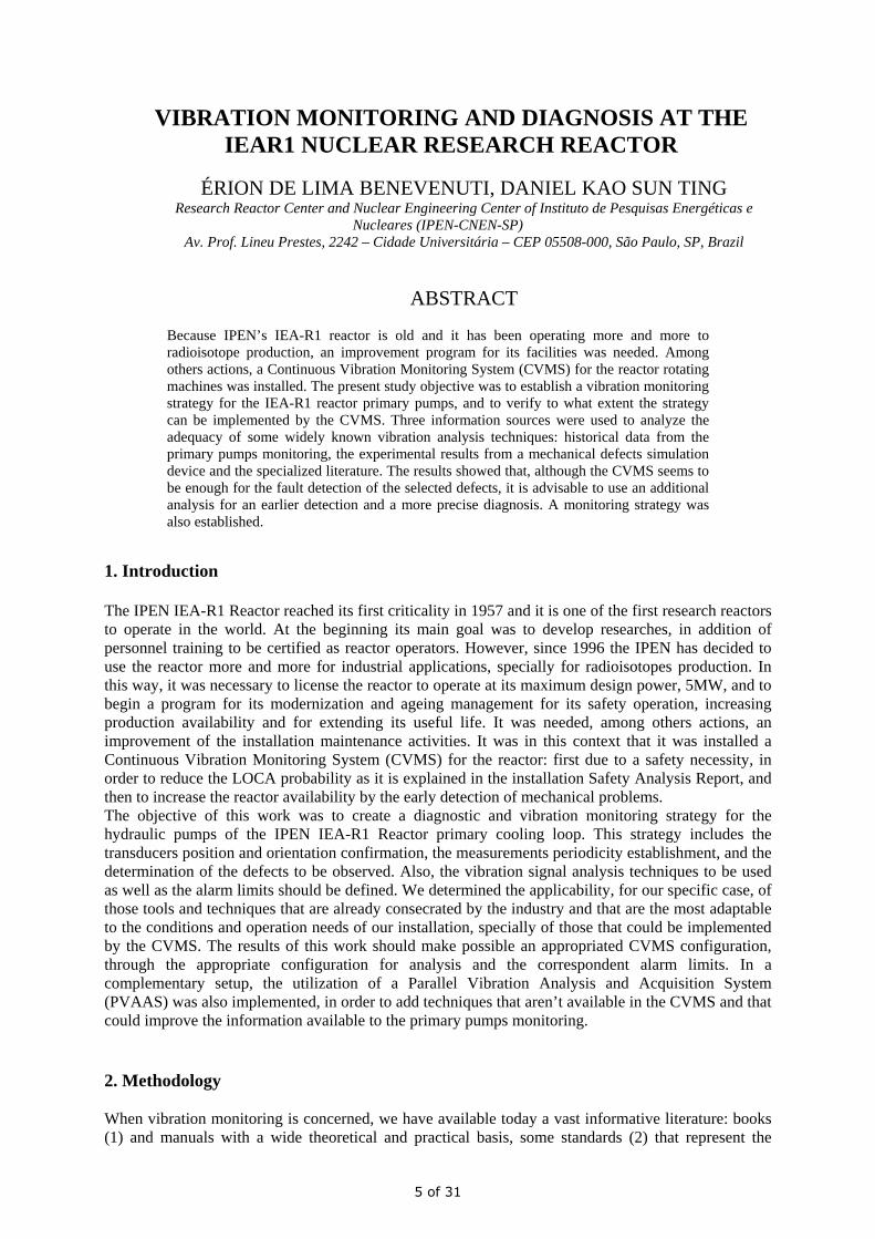
accumulated industrial experience about the relationship between the vibration severity and the monitored machine conditions, as well as a reasonable quantity of papers (3,4) that prove and establish the use of all known tools in this field. However, it is also known that the application of this knowledge in actual situations is not a trivial activity, of simple transposition of the theory to the case in question. The way and the degree of efficiency in the use of different known vibration monitoring techniques depends a lot on the real situation: the correct application of the techniques will depend a lot on the historical experience with the vibration behavior of the machine to be monitored. The essential part of this work focused on the historical verification of the functionality of some vibration analysis techniques that seemed to be more appropriated to the real situation of the plant and of the available monitoring equipments. As the CVMS does not give access to the raw data and its analysis have a closed format, it was necessary to utilize the PVAAS, that was used also to try others complementary tools. Besides that and since the pumps are part of the reactor protection system and due to the impossibility to test mechanical defects on them, it was decided to utilize a Mechanical Defect Simulation Machine (MDSM) to perform experiments that allow for a wider and more detailed analysis of the probable defects of the primary pumps. The MDSM also served to confirm the results with the primary pumps and to verify the Matlab programmed algoritms used in PVAAS for the analysis. 2.1 The primary pumps The primary pump is a centrifugal pump of 100Hp and a rotation speed of 1780rpm. The Fig. 1 below shows its scheme and the CVMS accelerometers positions: the transducer direction is horizontal and radial at A1, vertical at A3, A4 and A5 and axial at A2 and A6.
2.2 The Continuous Vibration Monitoring System (CVMS) The CVMS (5) is composed by a vibration monitor, which is a modular system that does all the handling of the signals from the accelerometers and the events, and by a UNIX workstation that contains the monitoring softwares and the data base. The workstation is also used to configure and control all the monitoring system, besides doing the user interface. All the equipment is mounted in one of the Reactor control room racks. The system softwares allow the monitoring of the instrumented components, the establishment of up to two alarm levels for each measurement, the data processing and the results storage. The vibration measurements that are allowed by the current software are the peak, the RMS, the crest factor and the signal spectrum. 2.3 The Parallel Vibration Analysis and Acquisition System (PVAAS) The primary pumps vibration signals used by the PVAAS were acquired through the CVMS fixed accelerometers. They are sent independently to a conditioner, where they are amplified and filtered, following to an acquisition board, where they are digitalized, and finally they are stored in a lap-top by
6 of 31
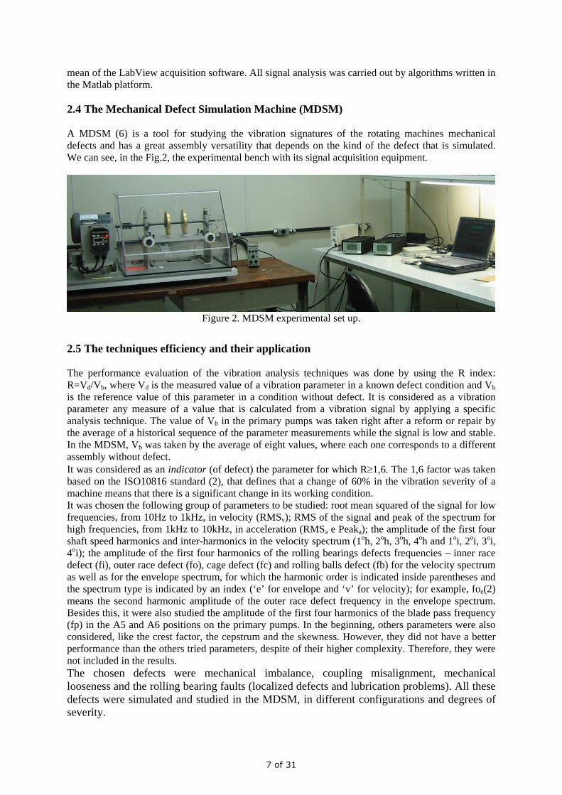
mean of the LabView acquisition software. All signal analysis was carried out by algorithms written in the Matlab platform. 2.4 The Mechanical Defect Simulation Machine (MDSM) A MDSM (6) is a tool for studying the vibration signatures of the rotating machines mechanical defects and has a great assembly versatility that depends on the kind of the defect that is simulated. We can see, in the Fig.2, the experimental bench with its signal acquisition equipment.
Figure 2. MDSM experimental set up.
2.5 The techniques efficiency and their application The performance evaluation of the vibration analysis techniques was done by using the R index: R=Vd/Vb, where Vd is the measured value of a vibration parameter in a known defect condition and Vb is the reference value of this parameter in a condition without defect. It is considered as a vibration parameter any measure of a value that is calculated from a vibration signal by applying a specific analysis technique. The value of Vb in the primary pumps was taken right after a reform or repair by the average of a historical sequence of the parameter measurements while the signal is low and stable. In the MDSM, Vb was taken by the average of eight values, where each one corresponds to a different assembly without defect. It was considered as an indicator (of defect) the parameter for which R≥1,6. The 1,6 factor was taken based on the ISO10816 standard (2), that defines that a change of 60% in the vibration severity of a machine means that there is a significant change in its working condition. It was chosen the following group of parameters to be studied: root mean squared of the signal for low frequencies, from 10Hz to 1kHz, in velocity (RMSv); RMS of the signal and peak of the spectrum for high frequencies, from 1kHz to 10kHz, in acceleration (RMSa e Peaka); the amplitude of the first four shaft speed harmonics and inter-harmonics in the velocity spectrum (1oh, 2oh, 3oh, 4oh and 1oi, 2oi, 3oi, 4oi); the amplitude of the first four harmonics of the rolling bearings defects frequencies – inner race defect (fi), outer race defect (fo), cage defect (fc) and rolling balls defect (fb) for the velocity spectrum as well as for the envelope spectrum, for which the harmonic order is indicated inside parentheses and the spectrum type is indicated by an index (‘e’ for envelope and ‘v’ for velocity); for example, foe(2) means the second harmonic amplitude of the outer race defect frequency in the envelope spectrum. Besides this, it were also studied the amplitude of the first four harmonics of the blade pass frequency (fp) in the A5 and A6 positions on the primary pumps. In the beginning, others parameters were also considered, like the crest factor, the cepstrum and the skewness. However, they did not have a better performance than the others tried parameters, despite of their higher complexity. Therefore, they were not included in the results. The chosen defects were mechanical imbalance, coupling misalignment, mechanical looseness and the rolling bearing faults (localized defects and lubrication problems). All these defects were simulated and studied in the MDSM, in different configurations and degrees of severity.
7 of 31
3. The results All the vibration signals of the primary pumps composing the data base have been collected during 30 months, once a month, with a sample frequency of 30kHz, low pass filter of 10kHz, high pass filter of 1Hz and a duration of 10s each. It has been done a historical comparison between all the events records and the results of the vibration analysis of all the collected data. The results of all historical comparison are summarized in the following Table1. Table 1. Indicators on primary pumps.
mechanical imbalance
coupling misalignment
mechanical looseness
bearing outer racedefect
bearing inner race defect
bearing balls defect
bearing lubrication problem
1oh, RMSv 2oh, 4oh RMSv
1oh, 2oi, 3oi 4oi, fp(2) RMSv
fov(1,2,3) RMSv
fiv(1,2,3,4) fie(1,2,3,4),RMSa Peaka, RMSv
fbe(1,2,3,4) 1oh, 2oh, 3oh, 4oh fov(1,2,3), foe(2,3,4), RMSv
The Table 2 presents the main MDSM results, where the “common indicators” represent the parameters that were indicators in all tested cases for the defect in question, while the “best directions” and the “best parameters” were those with the higher values of R. Table 2. Main results with MDSM. defect common indicators best direction best parameters mechanical imbalance 1oh H 1oh coupling misalignment 2oh mechanical looseness H 2oh, 3oh, 4oh bearing outer race foe(1,2,4), Peaka H foe(1,2,4) bearing inner race fie(1,2,3,4), fiv(1,2,4), RMSa, Peaka, RMSv H fie(1,2,3,4) bearing balls fbe(1,2,3,4), fbv(3,4), RMSa, Peaka V fbe(1,2,3,4) bearing cage RMSa, Peaka H Peaka bearing lubrication fov(1) V fov(1)
The envelope spectrum was more efficient than the velocity spectrum in all tested rolling bearings defects, except for the cage defects and the lubrication problems. 3.1 Monitoring strategy and diagnosis The defects considered for monitoring of the primary pumps – mechanical imbalance, coupling misalignment, mechanical looseness and rolling bearings faults – have been chosen due to the mechanical characteristics of the pumps, safety and operational requirements, and the present industrial experience. The safety requirements that implicated in the acquisition of CVMS may be more seriously jeopardized by mechanical looseness and rolling bearings defects. The positions of the CVMS accelerometers on the primary pumps were confirmed both by the conformity with the literature, that indicates that the accelerometers should be positioned as closer as possible to the bearings, and by the MDSM results, that indicate that the radial directions are the best for the detection of the considered defects. The two axial accelerometers on the primary pump are also in conformity with the literature, that states that the imbalance of the hanging rotors may be more easily detectable in this direction, as well as in conformity with the pumps results, that presented an indicator in the axial direction for looseness in the bearing box. The axial positions from two of the CVMS accelerometers are also in agreement with the MDSM results, which pointed that a conjugated imbalance may be better detected in the axial direction. The results with the primary pumps point out that the continuous monitoring by CVMS, in addition to a monthly measurement of their vibration signals for a more detailed analysis using the PVAAS, has been enough to assure their safe operation.
8 of 31
The vibration parameters for the primary pumps monitoring, presented on following Table 3, were defined based on those which were indicators on the pumps themselves and, as a complement, from those that were “indicators” or showed some correlation with the defect (R>1) in the MDSM experiments. Table 3. Vibration parameters for the primary pumps monitoring. mechanical imbalance
coupling misalignment
mechanical looseness
rolling bearing localized defects (rbld)
lubrication problems in rolling bearings
1oh,2oh, RMSv
2oh,4oh,RMSv 1oh,2oh,3oh,4oh, 2oi,3oi,4oi, RMSv,fp(1,2,3,4)
the first four harmonics of fov,fiv,fbv,fcv,foe, fie,fbe,fce RMSa, Peaka, RMSv
all the parameters of rbld plus 1oh, 2oh,3oh, 4oh
The CVMS alarm limits for the primary pumps were established based on the ISO10816 standard, that evaluates the working condition of the rotating machines by their vibration signals severity. The R=2 and R=3,2 values were used as the relation between the two alarm levels and the reference value for each considered vibration measurement, because the standard uses these same values to establish the relation between the alert and danger state level and the normality state level of the equipment, for the type of the machine being monitored. 4) Conclusions The obtained results showed that CVMS has been able to detect all mechanical defects of the primary pumps that could jeopardize the reactor safety. The bibliographical research and the MDSM results indicate that the use of some additional analysis to the ones done by CVMS, such as the envelope analysis, increases the safety and speed on the detection of mechanical defects on those equipments. However, the results also reveal that the detection of mechanical defects by vibration monitoring is a complex activity and many parameters must be observed simultaneously to make possible their discrimination. The experience provided by this work points to the high value of the knowledge that can be obtained through a machine such as MDSM, both to elaborate a monitoring strategy and to train people that want to dedicate themselves to the activity of vibration monitoring. The possibility to make tests of defects in a concrete rotating machine adds information and even a feeling that cannot be acquired in any kind of literature. Another relevant observation refers to the importance of having direct access to the raw signal and to the capability of doing its analysis in a more flexible way than that allowed by most of monitoring systems available in the market. Three years have passed since the conclusion of this work and the implementation of CVMS new configuration. And after that, the vibration monitoring of the primary pumps has been done with more efficiency, safety and confidence by the reactor operation staff. 5) References 1- Wowk V., 1991, “Machinery Vibration – Measurement and Analysis”, McGraw-Hill. 2- International Standard ISO 10816, 1995, “Mechanical vibration – Evaluation of machine vibration by measurements on non-rotating parts”. 3- Jones R.M., 1994, “A Guide to the Interpretation of Machinery Vibration Measurements”, Part I and Part II, SKF Conditioning Monitoring, Herndon, Virginia, Sound and Vibration, May, 24-35, and September, 12-20. 4- Tandon N., Nakra B.C., 1992, “Vibration and Acoustic Monitoring Techniques for the Detection of Defects in Rolling Element Bearing – A Review”, Shock and vibration digest, Vol.24 (3):3-11. 5- Brüel & Kjaer, 1994, “COMPASS Machine Monitoring System Type 3540 – User Manual”. 6- Spectra Quest, Inc, 1997, “User Operating Manual for Machinery Fault Simulator”.
9 of 31
NEW SILICON IRRADIATION RIG DESIGN FOR OPAL REACTOR
P.E. AMOS & S. KIM
Nuclear Mechanical Services Unit, Technical Services & Facilities Management,
Australian Nuclear Science and Technology Organisation (ANSTO) New Illawarra Road, Lucas Heights NSW 2234, Australia
ABSTRACT
Described is an overview of NTD silicon processing facilities in ANSTO’s OPAL reactor. A suite of six (6) high capacity Neutron Transmutation Doping (NTD) silicon rigs have been developed and installed. Optimum quality of the arrays is achieved through rotation of the silicon in the rigs to ensure even neutron fluence. The innovative design features a simple combination of water bearing and drive/rotation utilising reactor pool water. A hydrostatic water bearing ensures that there is no physical contact between the single moving component and static rig housing during operation. This design overcomes many of the existing reliability and maintenance issues involved with typical mechanical drive systems. The resulting layout leaves the pool area clear of obstructions which might obscure vision and hinder target handling for operators. Ingot handling systems are also provided to ensure the safe and efficient transfer of silicon between poolside and irradiation positions.
1 Introduction OPAL achieved full power of 20MW in November 2006 and is currently being commissioned. Its official opening is scheduled for April 2007. OPAL replaces HIFAR which was finally shutdown for decommissioning on 30th January 2007 after 49 years of successful operations. HIFAR, having produced high quality, high conductivity silicon for the computer industry for many years, has allowed a unique opportunity to redevelop new silicon neutron transmutation doping (NTD) facilities for OPAL. With high volume and high quality NTD facilities set as a priority from the point of conceptual design, the new facilities could be truly integrated and optimised for performance whilst meeting all design criteria and user needs. This paper briefly describes the unique design features of the silicon irradiation rigs and the associated monitoring and handling equipment necessary for a production process.
2 Silicon Neutron Transmutation Doping (NTD) The silicon NTD process is used to produce a high quality semiconductor, N-type silicon, with precisely defined resistivity of less than 5% variation, thereby increasing the efficiency of the silicon in conducting electricity, an essential characteristic for the electronics industry. Depending on the fluence of neutrons absorbed, the transmutation process converts a proportion of silicon atoms to phosphorus atoms in the silicon single crystal:
Si30 + neutron → Si31 → P31
Six NTD irradiation positions are situated vertically in the heavy water reflector vessel, which surrounds the reactor core, as shown in Figure 1. Each irradiation position has the capacity for a 600mm high array of mono-crystalline silicon ingots. The nominal diameters of ingots that can be irradiated are 4” (100mm), 5” (127mm), 6” (152mm) and 8” (203mm) depending on the irradiation positions and canisters used.
10 of 31
NTD positions
Reactor Pool Service Pool
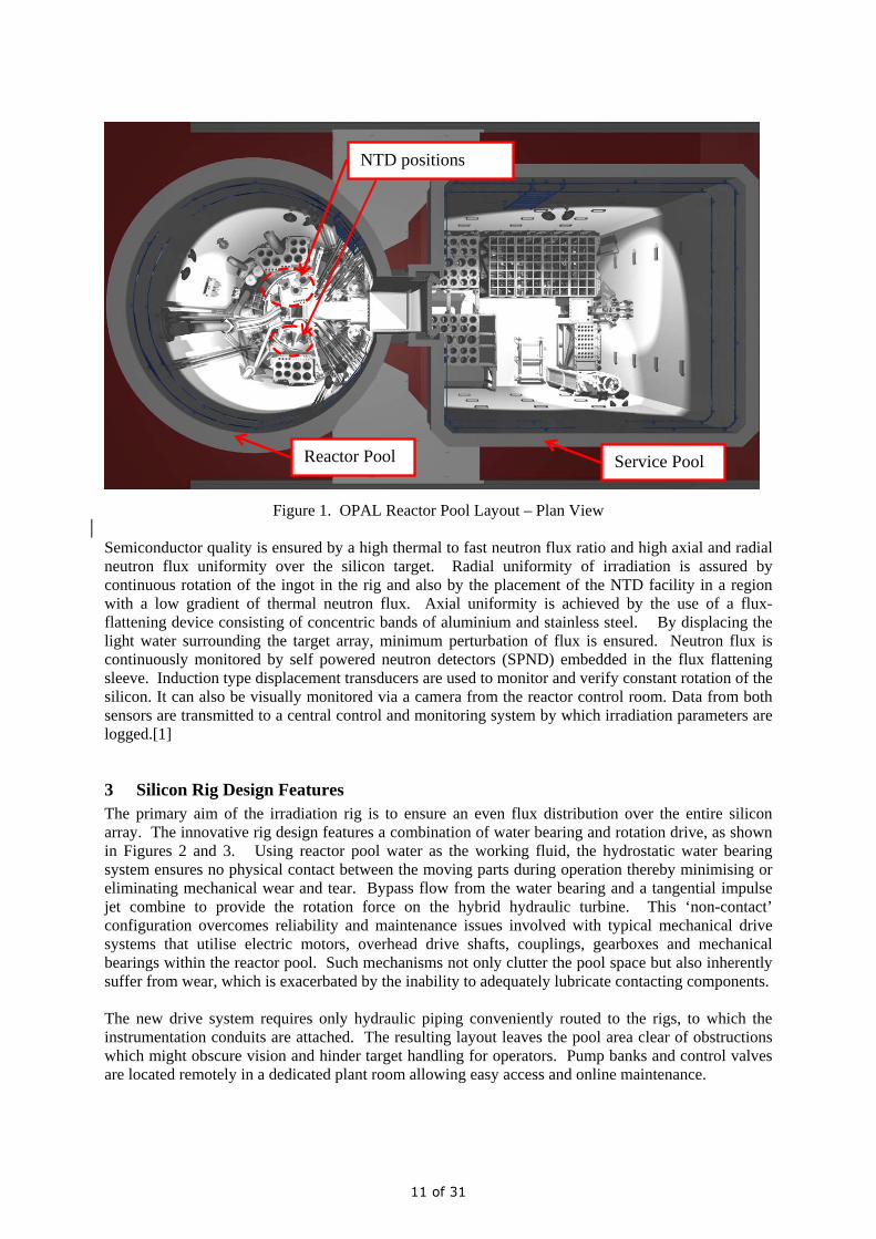
Figure 1. OPAL Reactor Pool Layout – Plan View
Semiconductor quality is ensured by a high thermal to fast neutron flux ratio and high axial and radial neutron flux uniformity over the silicon target. Radial uniformity of irradiation is assured by continuous rotation of the ingot in the rig and also by the placement of the NTD facility in a region with a low gradient of thermal neutron flux. Axial uniformity is achieved by the use of a flux-flattening device consisting of concentric bands of aluminium and stainless steel. By displacing the light water surrounding the target array, minimum perturbation of flux is ensured. Neutron flux is continuously monitored by self powered neutron detectors (SPND) embedded in the flux flattening sleeve. Induction type displacement transducers are used to monitor and verify constant rotation of the silicon. It can also be visually monitored via a camera from the reactor control room. Data from both sensors are transmitted to a central control and monitoring system by which irradiation parameters are logged.[1]
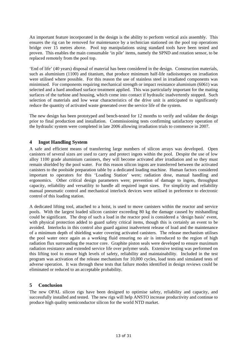
3 Silicon Rig Design Features The primary aim of the irradiation rig is to ensure an even flux distribution over the entire silicon array. The innovative rig design features a combination of water bearing and rotation drive, as shown in Figures 2 and 3. Using reactor pool water as the working fluid, the hydrostatic water bearing system ensures no physical contact between the moving parts during operation thereby minimising or eliminating mechanical wear and tear. Bypass flow from the water bearing and a tangential impulse jet combine to provide the rotation force on the hybrid hydraulic turbine. This ‘non-contact’ configuration overcomes reliability and maintenance issues involved with typical mechanical drive systems that utilise electric motors, overhead drive shafts, couplings, gearboxes and mechanical bearings within the reactor pool. Such mechanisms not only clutter the pool space but also inherently suffer from wear, which is exacerbated by the inability to adequately lubricate contacting components. The new drive system requires only hydraulic piping conveniently routed to the rigs, to which the instrumentation conduits are attached. The resulting layout leaves the pool area clear of obstructions which might obscure vision and hinder target handling for operators. Pump banks and control valves are located remotely in a dedicated plant room allowing easy access and online maintenance.
11 of 31
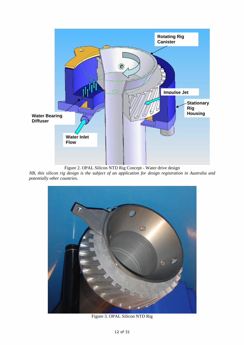
Figure 2. OPAL Silicon NTD Rig Concept - Water drive design
NB, this silicon rig design is the subject of an application for design registration in Australia and potentially other countries.
Figure 3. OPAL Silicon NTD Rig
Water Bearing Diffuser
Water Inlet Flow
Impulse Jet
Rotating Rig Canister
Stationary Rig Housing
12 of 31
An important feature incorporated in the design is the ability to perform vertical axis assembly. This ensures the rig can be removed for maintenance by a technician stationed on the pool top operations bridge over 15 metres above. Pool top manipulations using standard tools have been tested and proven. This enables the main consumable ‘in pile’ items, namely the SPND and rotation sensor, to be replaced remotely from the pool top. ‘End of life’ (40 years) disposal of material has been considered in the design. Construction materials, such as aluminium (1100) and titanium, that produce minimum half-life radioisotopes on irradiation were utilised where possible. For this reason the use of stainless steel in irradiated components was minimised. For components requiring mechanical strength or impact resistance aluminium (6061) was selected and a hard anodised surface treatment applied. This was particularly important for the mating surfaces of the turbine and housing, which come into contact if hydraulic inadvertently stopped. Such selection of materials and low wear characteristics of the drive unit is anticipated to significantly reduce the quantity of activated waste generated over the service life of the system. The new design has been prototyped and bench-tested for 12 months to verify and validate the design prior to final production and installation. Commissioning tests confirming satisfactory operation of the hydraulic system were completed in late 2006 allowing irradiation trials to commence in 2007.
4 Ingot Handling System A safe and efficient means of transferring large numbers of silicon arrays was developed. Open canisters of several sizes are used to carry and protect ingots within the pool. Despite the use of low alloy 1100 grade aluminium canisters, they will become activated after irradiation and so they must remain shielded by the pool water. For this reason silicon ingots are transferred between the activated canisters to the poolside preparation table by a dedicated loading machine. Human factors considered important to operators for this ‘Loading Station’ were; radiation dose, manual handling and ergonomics. Other critical design parameters were; prevention of damage to ingots, throughput capacity, reliability and versatility to handle all required ingot sizes. For simplicity and reliability manual pneumatic control and mechanical interlock devices were utilised in preference to electronic control of this loading station. A dedicated lifting tool, attached to a hoist, is used to move canisters within the reactor and service pools. With the largest loaded silicon canister exceeding 80 kg the damage caused by mishandling could be significant. The drop of such a load in the reactor pool is considered a ‘design basis’ event, with physical protection added to guard safety critical items, though this is certainly an event to be avoided. Interlocks in this control also guard against inadvertent release of load and the maintenance of a minimum depth of shielding water covering activated canisters. The release mechanism utilises the pool water once again as a working fluid ensuring no air is introduced to the region of high radiation flux surrounding the reactor core. Graphite piston seals were developed to ensure maximum radiation resistance and extended service life over polymer seals. Extensive testing was performed on this lifting tool to ensure high levels of safety, reliability and maintainability. Included in the test program was activation of the release mechanism for 10,000 cycles, load tests and simulated tests of adverse operation. It was through these tests that failure modes identified in design reviews could be eliminated or reduced to an acceptable probability.
5 Conclusion The new OPAL silicon rigs have been designed to optimise safety, reliability and capacity, and successfully installed and tested. The new rigs will help ANSTO increase productivity and continue to produce high quality semiconductor silicon for the world NTD market.
13 of 31

6 Acknowledgements Development of the OPAL silicon NTD facilities has been undertaken by ANSTO Technical Services & Facilities Management (http://home.ansto.gov.au/ansto/eng.html). Additional support was provided from other ANSTO divisions in close collaboration with INVAP. This paper is the work of all those involved in the project. Special credit goes to Michael Deura who led the project through the conceptual design and Alec Kimber who completed the successful commissioning.
7 References [1] D. F. Hergenreder, “MCNP design of high performance NTD facilities” International conference on research reactor utilization, safety, decommissioning, fuel and waste management Santiago (Chile) 10-14 Nov 2003. [2] ANSTO Annual Report 2005-06 [3] ANSTO website: www.ansto.gov.au
14 of 31
MEASUREMENT OF VOID FRACTION IN HYDROGEN MODERATOR USED FOR MODERATOR CELL OF HANARO
COLD NEUTRON SOURCE
MYONG-SEOP KIM*, JUNGWOON CHOI, YOUNG-CHIL KIM, DONG-GIL HWANG, SANG-BEOM HONG AND KYE-HONG LEE
Korea Atomic Energy Research Institute 150 Dukjin-Dong, Yuseong, Daejeon, 305-353, Korea, * [email protected]
ABSTRACT
The void fraction in the hydrogen moderator used for the moderator cell of the HANARO cold neutron source was measured by using a gamma densitometer technique. A mock-up of the HANARO CNS facility with an electrical heating system as the heat source instead of radiations was constructed. The attenuation of the 59.5 keV gamma-rays from Am-241 through the hydrogen medium was measured by using an HPGe detector. The void fractions were measured for stable thermo-siphon loops with several heat loads applied to the moderator cell. The geometrical distribution of the void fraction was determined. The void fraction measured at a heat load of 720 W had values of 8~41% depending on the height from the bottom of the moderator cell. The void fraction determined at the expected nuclear heating power for this moderator cell was about 20%. These measurements will be very useful for the design and operation of the HANARO cold neutron source.
1. Introduction The design and installation of a cold neutron source (CNS) facility for HANARO, a 30 MW research reactor, is in progress. The in-pool assembly consists of a two phase thermo-siphon loop and a vacuum chamber. Liquid hydrogen has been selected as the moderator. In order to validate the assembly design concept, a thermo-siphon mock-up test is being conducted. A mock-up of the HANARO CNS facility with an electrical heating system as the heat source instead of radiations has been constructed. The void fraction in the hydrogen moderator is one of the important parameters for the operation of the moderator cell in a cold neutron facility since it affects the moderation capability and the stability of a cold neutron source [1]. Therefore, one of the major purposes of this mock-up test was to provide information related to the void fraction in a two-phase hydrogen moderator to confirm the performance of the HANARO cold neutron facility.
Measurements of the void fraction are of considerable technical importance for two-phase systems in many industrial applications such as nuclear reactors, chemical processing plants and the oil industry [2]. Various methods have been proposed for the measurement of a void fraction, and among these methods, the most widely used ones are the volumetric, electrical, ultrasonic, and radiation attenuation techniques. The radiation attenuation technique, especially, the gamma densitometer technique is widely applied for the measurement of the void fraction of various systems including a cryogenic two-phase system because it is non-intrusive, and in general, quite reliable and easy to apply [3,4].
In this work, we measured the void fraction in the hydrogen moderator in the moderator cell of the mock-up for the HANARO in-pool assembly by using a gamma densitometer technique. We designed and installed a densitometer by using an HPGe detector and an Am-241 gamma-ray source, and measured the void fraction and its distribution in the moderator cell. These measurements will be very useful for a characterization of the HANARO cold neutron facility. 2. Void fraction measurement by gamma densitometer
15 of 31
The gamma-ray attenuation technique is based on the fact that the intensity of a collimated gamma-ray beam decreases exponentially as it passes through matter [2,4]. For a two-phase flow, a void fraction can be obtained easily by
)/ln()/ln(
LG
LIIIIαα = , (1)
where, αI is the gamma-ray intensity measured by a detector for an arbitrary void fraction, GI and LI are the intensities measured for a single-phase vapour and a single-phase liquid, respectively. When the signal processing system of a gamma densitometer is operated in the count mode, the measured intensity can be represented by the counting rates of the gamma-ray detector. 3. Experimental setup The mock-up test facility for the cold neutron source of HANARO is composed of an in-pool assembly (IPA) connected to a hydrogen buffer tank, a vacuum system, and a helium refrigeration system. The IPA consists of a vacuum vessel, a moderator cell, a transfer tube, a heat exchanger and the related piping. Additionally, several sensors and heaters are installed in the IPA for the test.
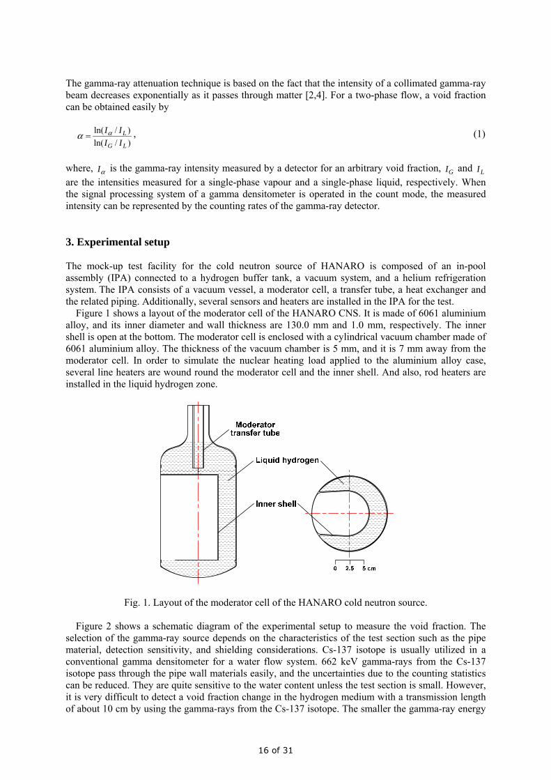
Figure 1 shows a layout of the moderator cell of the HANARO CNS. It is made of 6061 aluminium alloy, and its inner diameter and wall thickness are 130.0 mm and 1.0 mm, respectively. The inner shell is open at the bottom. The moderator cell is enclosed with a cylindrical vacuum chamber made of 6061 aluminium alloy. The thickness of the vacuum chamber is 5 mm, and it is 7 mm away from the moderator cell. In order to simulate the nuclear heating load applied to the aluminium alloy case, several line heaters are wound round the moderator cell and the inner shell. And also, rod heaters are installed in the liquid hydrogen zone.
Fig. 1. Layout of the moderator cell of the HANARO cold neutron source.
Figure 2 shows a schematic diagram of the experimental setup to measure the void fraction. The selection of the gamma-ray source depends on the characteristics of the test section such as the pipe material, detection sensitivity, and shielding considerations. Cs-137 isotope is usually utilized in a conventional gamma densitometer for a water flow system. 662 keV gamma-rays from the Cs-137 isotope pass through the pipe wall materials easily, and the uncertainties due to the counting statistics can be reduced. They are quite sensitive to the water content unless the test section is small. However, it is very difficult to detect a void fraction change in the hydrogen medium with a transmission length of about 10 cm by using the gamma-rays from the Cs-137 isotope. The smaller the gamma-ray energy
16 of 31
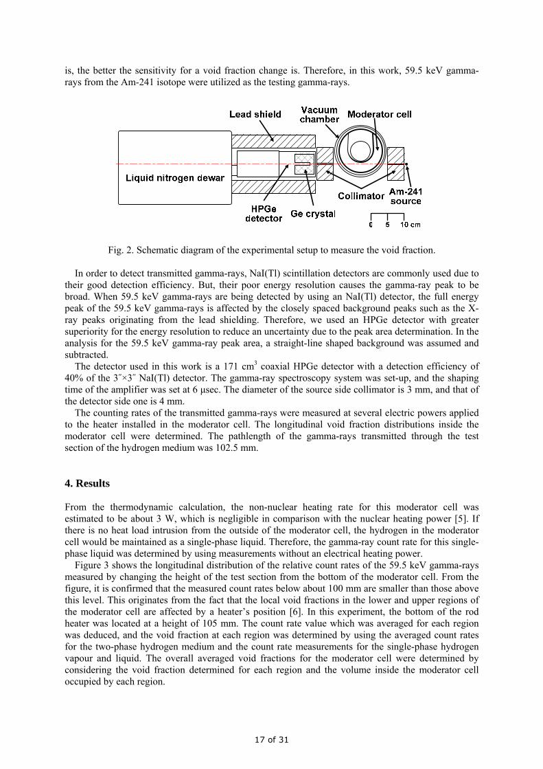
is, the better the sensitivity for a void fraction change is. Therefore, in this work, 59.5 keV gamma-rays from the Am-241 isotope were utilized as the testing gamma-rays.
Fig. 2. Schematic diagram of the experimental setup to measure the void fraction.
In order to detect transmitted gamma-rays, NaI(Tl) scintillation detectors are commonly used due to their good detection efficiency. But, their poor energy resolution causes the gamma-ray peak to be broad. When 59.5 keV gamma-rays are being detected by using an NaI(Tl) detector, the full energy peak of the 59.5 keV gamma-rays is affected by the closely spaced background peaks such as the X-ray peaks originating from the lead shielding. Therefore, we used an HPGe detector with greater superiority for the energy resolution to reduce an uncertainty due to the peak area determination. In the analysis for the 59.5 keV gamma-ray peak area, a straight-line shaped background was assumed and subtracted.
The detector used in this work is a 171 cm3 coaxial HPGe detector with a detection efficiency of 40% of the 3˝×3˝ NaI(Tl) detector. The gamma-ray spectroscopy system was set-up, and the shaping time of the amplifier was set at 6 μsec. The diameter of the source side collimator is 3 mm, and that of the detector side one is 4 mm.
The counting rates of the transmitted gamma-rays were measured at several electric powers applied to the heater installed in the moderator cell. The longitudinal void fraction distributions inside the moderator cell were determined. The pathlength of the gamma-rays transmitted through the test section of the hydrogen medium was 102.5 mm. 4. Results From the thermodynamic calculation, the non-nuclear heating rate for this moderator cell was estimated to be about 3 W, which is negligible in comparison with the nuclear heating power [5]. If there is no heat load intrusion from the outside of the moderator cell, the hydrogen in the moderator cell would be maintained as a single-phase liquid. Therefore, the gamma-ray count rate for this single-phase liquid was determined by using measurements without an electrical heating power.
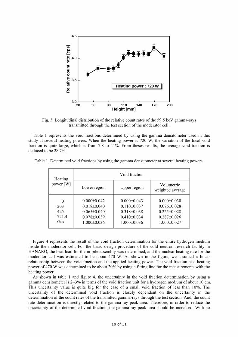
Figure 3 shows the longitudinal distribution of the relative count rates of the 59.5 keV gamma-rays measured by changing the height of the test section from the bottom of the moderator cell. From the figure, it is confirmed that the measured count rates below about 100 mm are smaller than those above this level. This originates from the fact that the local void fractions in the lower and upper regions of the moderator cell are affected by a heater’s position [6]. In this experiment, the bottom of the rod heater was located at a height of 105 mm. The count rate value which was averaged for each region was deduced, and the void fraction at each region was determined by using the averaged count rates for the two-phase hydrogen medium and the count rate measurements for the single-phase hydrogen vapour and liquid. The overall averaged void fractions for the moderator cell were determined by considering the void fraction determined for each region and the volume inside the moderator cell occupied by each region.
17 of 31
20 50 80 110 140 170 2003.0
3.5
4.0
4.5
Heating power : 720 W
Rel
ativ
e co
unt r
ate
[cps
]
Height [mm]
Fig. 3. Longitudinal distribution of the relative count rates of the 59.5 keV gamma-rays transmitted through the test section of the moderator cell.
Table 1 represents the void fractions determined by using the gamma densitometer used in this
study at several heating powers. When the heating power is 720 W, the variation of the local void fraction is quite large, which is from 7.8 to 41%. From theses results, the average void traction is deduced to be 28.7%.
Table 1. Determined void fractions by using the gamma densitometer at several heating powers.
Void fraction Heating
power [W] Lower region Upper region Volumetric
weighted average
0 203 425 721.4 Gas
0.000±0.042 0.018±0.040 0.065±0.040 0.078±0.039 1.000±0.036
0.000±0.043 0.110±0.037 0.318±0.038 0.410±0.034 1.000±0.036
0.000±0.030 0.076±0.028 0.225±0.028 0.287±0.026 1.000±0.027
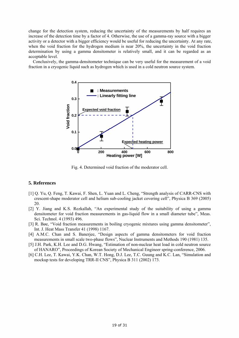
Figure 4 represents the result of the void fraction determination for the entire hydrogen medium
inside the moderator cell. For the basic design procedure of the cold neutron research facility in HANARO, the heat load for the in-pile assembly was determined, and the nuclear heating rate for the moderator cell was estimated to be about 470 W. As shown in the figure, we assumed a linear relationship between the void fraction and the applied heating power. The void fraction at a heating power of 470 W was determined to be about 20% by using a fitting line for the measurements with the heating power.
As shown in table 1 and figure 4, the uncertainty in the void fraction determination by using a gamma densitometer is 2~3% in terms of the void fraction unit for a hydrogen medium of about 10 cm. This uncertainty value is quite big for the case of a small void fraction of less than 10%. The uncertainty of the determined void fraction is closely dependent on the uncertainty in the determination of the count rates of the transmitted gamma-rays through the test section. And, the count rate determination is directly related to the gamma-ray peak area. Therefore, in order to reduce the uncertainty of the determined void fraction, the gamma-ray peak area should be increased. With no
18 of 31
change for the detection system, reducing the uncertainty of the measurements by half requires an increase of the detection time by a factor of 4. Otherwise, the use of a gamma-ray source with a bigger activity or a detector with a bigger efficiency would be useful for reducing the uncertainty. At any rate, when the void fraction for the hydrogen medium is near 20%, the uncertainty in the void fraction determination by using a gamma densitometer is relatively small, and it can be regarded as an acceptable level.
Conclusively, the gamma-densitometer technique can be very useful for the measurement of a void fraction in a cryogenic liquid such as hydrogen which is used in a cold neutron source system.
0 200 400 600 8000.0
0.1
0.2
0.3
0.4
Expected void fraction
Expected heating power
: Measurements : Linearly fitting line
Voi
d fr
actio
n
Heating power [W]
Fig. 4. Determined void fraction of the moderator cell.
5. References [1] Q. Yu, Q. Feng, T. Kawai, F. Shen, L. Yuan and L. Cheng, “Strength analysis of CARR-CNS with
crescent-shape moderator cell and helium sub-cooling jacket covering cell”, Physica B 369 (2005) 20.
[2] Y. Jiang and K.S. Rezkallah, “An experimental study of the suitability of using a gamma densitometer for void fraction measurements in gas-liquid flow in a small diameter tube”, Meas. Sci. Technol. 4 (1993) 496.
[3] R. Bøe, “Void fraction measurements in boiling cryogenic mixtures using gamma densitometer”, Int. J. Heat Mass Transfer 41 (1998) 1167.
[4] A.M.C. Chan and S. Banerjee, “Design aspects of gamma densitometers for void fraction measurements in small scale two-phase flows”, Nuclear Instruments and Methods 190 (1981) 135.
[5] J.H. Park, K.H. Lee and D.G. Hwang, “Estimation of non-nuclear heat load in cold neutron source of HANARO”, Proceedings of Korean Society of Mechanical Engineer spring-conference, 2006.
[6] C.H. Lee, T. Kawai, Y.K. Chan, W.T. Hong, D.J. Lee, T.C. Guung and K.C. Lan, “Simulation and mockup tests for developing TRR-II CNS”, Physica B 311 (2002) 173.
19 of 31
OPTIMISATION OF THE POOLSIDE FACILITY FOR NEUTRON DOPING OF SILICON IN HIGH FLUX
MATERIALS TESTING REACTOR BR2
V.KUZMINOV, H.BLOWFIELD
SCK•CEN, Boeretang 200, B-2400 – Belgium
ABSTRACT The paper contains a description of the optimisation procedure performed during a design study of the poolside facility at the High Flux Materials Testing Reactor BR2 for neutron doping of large silicon crystals. Analysis of different moderator materials to maintain thermal neutron flux distributions in silicon crystals and the influence of geometrical design of the facility on neutron flux distributions and on nuclear heating were performed during the optimisation. Special attention in the design was paid for the feedback reactivity effect in the BR2 reactor core and to nuclear heating in moderator. A description of several variants of the poolside facility for irradiation of silicon crystals of the diameter 15-20 cm in the reactor pool of the BR2 is included in the present paper.
1. Introduction When the High Flux Materials Testing Reactor BR2 first ventured into the Neutron Transmutation Doping (NTD) silicon business in 1992, the demand for 4 and 5-inch diameter irradiations was about equal. By 2003, this trend had completely shifted towards 5-inch whilst latterly a requirement for 6-inch is rapidly becoming the norm. By the end of 2000, demand for NTD-Silicon production in BR2 began to exceed the available capacity of its existing silicon irradiation facility (SIDONIE). The commercial revenue generated for SCK•CEN by this device is considered to be an important contribution towards BR2’s operating costs. However, this source of income is entirely dependant on the availability of only one 5-inch production facility which cannot be easily modified to meet today's increasing demand for 6-inch capacity nor can it be adapted to accommodate 8-inch diameter silicon irradiations! More recently, customers have begun to anticipate their production requirements for 8-inch irradiations to meet the automotive industries fast growing demand for Insulated Gate Bipolar Transistors (IGBTs). World leading car manufacturers consider the production of these key electronic devices from 8-inch silicon to be an important part of their overall strategy which is aimed at reducing the price of the next generation of super fuel efficient Hybrid Electric Vehicles (HEV). Although BR2 has horizontal beam tubes that could easily accommodate 6-inch and possibly 8-inch diameter silicon crystals, they do not have an adequate production capability to be cost effective and to meet the current demand! Therefore, a scheme has been conceived for a pool-side facility (PSF) that is not constrained by the geometry of BR2’s existing reactor pressure vessel (RPV) through-holes or channels. The largest being only 200-mm in diameter of which one is already occupied by SIDONIE.
20 of 31
2 Primary Objectives of the Study Throughout the conceptual evolution of this project, the 'keystone' of its technical analysis has been the determination of the neutronic conditions that will exist within the proposed variants for a PSF. This has been carried out by BR2's Reactor Physics Group using a full-scale 3-D Model of the BR2 reactor to use as input data for the MCNP-4C Monte Carlo code. In particular, the information generated during optimisation has been used to determine:
• the most feasible scheme configuration. • the optimum material for use as a neutron moderator • the integrated (perturbed) thermal neutron flux density in each of the irradiation
channels. Clearly, this is key data for establishing the NTD-Silicon production capacity of the PSF and hence its financial feasibility
• the spatial and axial distribution of the thermal neutron flux in the Si crystals. This is also critical information that is needed for assessing the technical feasibility of the scheme in terms of its capability to achieve a homogeneous resistivity profile and thereby keep Axial Resistivity Gradients (ARG) within acceptable limits
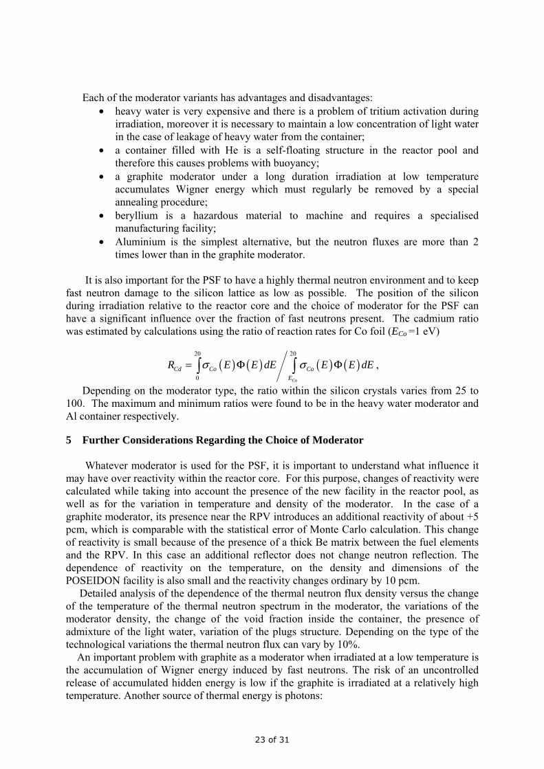
3 PSF Configuration Options Focusing on the poolside position of the irradiation device, several proposals of the conceptual design were analysed. In the Carrousel design it was planed to have 4 irradiation quadrants separated by Cd screens in order to reduce uncontrolled irradiation in sectors located at a large distance from the core. In this scheme, silicon crystals during irradiation were located at different distances from the reactor core and the thermal neutron fluxes in the silicon are different by one order of magnitude. Even if this fact is not taken into account, the dimension of such a device is too large to be installed in the available space in the pool of BR2. In the parallel-channel type PSF (Fig.1), silicon crystals are located in the box filled with a moderator in order to mitigate neutron absorption by light water in the reactor pool. The moderator box outside the reactor core mainly prevents the loss of thermal neutrons in the pool water and partially improves the thermal fluxes by additional slowing down of fast and epi-thermal neutrons escaping from the reactor core. All channels have a different neutron fluence because of radial and azimuth dependencies of the thermal flux density. This shortcoming can be diminished by positioning the channels in the form of an arc ( Fig.2). One of the most important requirements of the PSF is to facilitate the production of a uniform distribution of 31P within each of the silicon crystals. This can be achieved by a special procedure involving the physical positioning of the silicon inside the irradiation device. For this purpose, the flux profile with respect to its vertical axis must be at least symmetrical relative to a fixed position (inside the irradiation channel).
4 PSF Moderator Options Absorption of the thermal neutrons in the light water in the reactor pool is so that makes practically impossible to irradiate large crystals of 20 cm, diameter. Neutron absorption can be considerably diminished by using a container filled with a moderator with a low neutron absorption cross-section. Several candidate materials for a suitable moderator were considered: heavy water; helium-4; graphite; beryllium; aluminium.
21 of 31
The largest value of the mean neutron flux density in silicon crystals is in the container filled with heavy water, while the minimum flux is in the container filled with Aluminium. The thermal fluxes in silicon targets in the container filled with the inert gas He-4 are located between the maximum and the minimum values. The fluxes in the container filled with graphite and Be materials are slightly lower than that in the heavy water container. Examples of the thermal neutron flux distributions versus the material of neutron moderators is presented in Fig.1.
Fig.1. Schematic picture of parallel-channel proposal for Neutron Transmutation Doping silicon. The figure in the right shows a dependence of axial distributions of the mean thermal neutron flux density (in arbitrary units) in the silicon crystal versus the type of material of moderator.
Fig.2 Schematic view of the PSF irradiation device for Neutron Transmutation Doping silicon. The figure on the right shows an example of the dependence of axial distributions of the thermal neutron flux versus the position of silicon crystals in the moderator box.
-35 -30 -25 -20 -15 -10 -5 0 5 10 15 20 250.7
0.8
0.9
1.0
1.1
1.2
1.3
1.4
1.5
1.6
1.7
1.8
1.9
2.0
Al
4He
C
Be
D2O
Φ, a
.u.
Z, cm
-35 -30 -25 -20 -15 -10 -5 0 5 10 15 20 251.1
1.2
1.3
1.4
1.5
1.6
1.7
1.8
1.9
Φ, a
.u.
Z, cm
3 2 1 1a 2a 3a
22 of 31
Each of the moderator variants has advantages and disadvantages:
• heavy water is very expensive and there is a problem of tritium activation during irradiation, moreover it is necessary to maintain a low concentration of light water in the case of leakage of heavy water from the container;
• a container filled with He is a self-floating structure in the reactor pool and therefore this causes problems with buoyancy;
• a graphite moderator under a long duration irradiation at low temperature accumulates Wigner energy which must regularly be removed by a special annealing procedure;
• beryllium is a hazardous material to machine and requires a specialised manufacturing facility;
• Aluminium is the simplest alternative, but the neutron fluxes are more than 2 times lower than in the graphite moderator.
It is also important for the PSF to have a highly thermal neutron environment and to keep fast neutron damage to the silicon lattice as low as possible. The position of the silicon during irradiation relative to the reactor core and the choice of moderator for the PSF can have a significant influence over the fraction of fast neutrons present. The cadmium ratio was estimated by calculations using the ratio of reaction rates for Co foil (ECo =1 eV)
( ) ( ) ( ) ( )20 20
0 Co
Cd Co CoE
R E E dE E E dEσ σ= Φ Φ∫ ∫ ,
Depending on the moderator type, the ratio within the silicon crystals varies from 25 to 100. The maximum and minimum ratios were found to be in the heavy water moderator and Al container respectively.
5 Further Considerations Regarding the Choice of Moderator Whatever moderator is used for the PSF, it is important to understand what influence it may have over reactivity within the reactor core. For this purpose, changes of reactivity were calculated while taking into account the presence of the new facility in the reactor pool, as well as for the variation in temperature and density of the moderator. In the case of a graphite moderator, its presence near the RPV introduces an additional reactivity of about +5 pcm, which is comparable with the statistical error of Monte Carlo calculation. This change of reactivity is small because of the presence of a thick Be matrix between the fuel elements and the RPV. In this case an additional reflector does not change neutron reflection. The dependence of reactivity on the temperature, on the density and dimensions of the POSEIDON facility is also small and the reactivity changes ordinary by 10 pcm. Detailed analysis of the dependence of the thermal neutron flux density versus the change of the temperature of the thermal neutron spectrum in the moderator, the variations of the moderator density, the change of the void fraction inside the container, the presence of admixture of the light water, variation of the plugs structure. Depending on the type of the technological variations the thermal neutron flux can vary by 10%. An important problem with graphite as a moderator when irradiated at a low temperature is the accumulation of Wigner energy induced by fast neutrons. The risk of an uncontrolled release of accumulated hidden energy is low if the graphite is irradiated at a relatively high temperature. Another source of thermal energy is photons:
23 of 31
• the energy deposition induced by prompt photons produced in capture reactions; • the energy deposition from delayed photons generated by fission products. The energy deposition from prompt photons is calculated using the MCNP-4c code[1]. The energy spectrum and intensity of the delayed photons in the BR2 fuel elements were obtained from the SCALE-4.4a code [2] and used in the MCNP model for the transport calculations of photons from fission products. The heating from the β-decay reaction was calculated using the intensity of neutron capture reaction in structural elements. The PSF is primarily designed to irradiate silicon crystals of 8-inch diameters. However, when irradiating 6-inch diameter crystals, the free space is occupied by filler containing the same material as the moderator in the box. The mean non-uniformity factor of the thermal flux distribution inside the silicon crystals which was calculated for 8-inches and 6-inches silicon crystals is spread in the region from 0.98-1.07. However, the statistical errors of these results are comparable with the observed effect.
6 Conclusion In principal, the scheme adopted (POSEIDON) consists of six vertical, parallel-channels for the large volume production of 8-inch diameter NTD-Silicon. These form a concentric arc around the reactor core in a position that is immediately outside the RPV. The channels are located within a neutron moderator which displaces the reactor pool water from around them. Thereby, much of the thermal and epithermal neutron flux leakage from the reactor in this region is preserved for irradiating the silicon. The channels can be easily adapted with sleeves to provide for the bulk production of 6-inch diameter NTD-Silicon also. Located outside the reactor pressure vessel and operating quite independently of all BR2’s critical systems, POSIDON is currently configured to meet a very large proportion of the semiconductor industries foreseeable demand for 6 and 8-inches diameter NTD-Silicon production. This concept provides flexibility which allows it to be relatively easily reconfigured to accommodate even larger sizes of crystals or even a combination of 6-inch, 8-inch and possibly 12-inch diameters. POSEIDON provides a very financially economical and convenient method for producing NTD-Silicon in BR2 with key attributes that can be summarised by:
• a very large volume of production capacity capable of meeting demand for the foreseeable future
• the flexibility to irradiate 6-inch, 8-inch and possibly 12-inch diameter silicon • an irradiation environment with a cadmium ration that can be characterised as
highly desirable Due to these benefits, SCK●CEN has secured long-term agreements with all of the major customers for NTD-Silicon in Japan.
5. References
[1] J.F.Breismeister ,“MCNPTM – A General Monte Carlo N-Particle Transport Code.Version 4c”, LA-13709-M (2000). [2] SCALE 4.4a, NUREG/CR-0200, Revision 6, ORNL/NUREG/CSD-2/V2/R.
24 of 31
MATERIALS SURVEILLANCE PROGRAM FOR THE OPAL RESEARCH REACTOR
R.P. HARRISON, D.G. CARR, T. WEI, AND P.A. STATHERS Institute of Materials and Engineering Science, Australian Nuclear Science and Technology Organisation,
PMB 1, NSW, 2234, AUSTRALIA.
ABSTRACT
The OPAL research reactor has recently achieved full power and will commence normal operation in the early part of 2007. One aspect of the design of OPAL has been the inclusion of a surveillance program for the materials used in the reactor core regions. These materials are exposed to a high neutron flux and their properties, such as tensile strength, fracture toughness and physical dimensions (through radiation-induced growth), are expected to change through the life of the reactor. Estimates of these changes have been obtained from literature data and have been accommodated in the design. However, data at the operating temperature of OPAL is limited. In order to guarantee safe operation of these materials, a surveillance program was developed during the detailed design phase of the project. The program involves the placement of miniature samples in high flux regions close to the reactor core. These samples will be removed at intervals and will be subjected to extensive mechanical testing to determine any changes compared with samples in the unirradiated condition. Additional samples will be sectioned from other high-fluence components that will be removed well before the 40 year design life.
1. Introduction The OPAL nuclear research reactor has recently commenced full power operation. It was constructed as a replacement for HIFAR, which had given 49 years of safe and reliable operation but which had become unable to provide the range of neutron based experiments and production facilities that are required to take ANSTO and the Australian nuclear industry into the 21st century. As part of the specification for OPAL a program of sample irradiations forming part of a surveillance program was made a requirement of the design. The surveillance program that has eventuated is a combination of the original INVAP proposal plus extensive modifications which have arisen as part of the detailed engineering and construction phases of the project. The objective of the surveillance program is to monitor the core reactor materials to ensure that their mechanical properties are sufficient to ensure safe and reliable long-term operation of OPAL. The effects of greatest interest are the changes that neutron irradiation makes on the tensile and fracture properties of zirconium alloys and the possible affects of corrosion on all reactor materials. The objectives of the surveillance program will be met by placing a range of specimens in locations throughout the reactor pool (RPO) and which will be examined periodically during the 40 year design life of the reactor. This paper describes the methodology of the program, the test samples, their locations and the tests to which they will be subjected. Additional information will be provided on other specialised inspection procedures. 2. OPAL Research Reactor OPAL is a 20 MW pool-type research reactor, where the core is located at the bottom of a 13 m deep pool of demineralised water. A schematic view of the OPAL reactor pool and internal structures is given in Fig 1. This shows the main components and the location of the key items of interest in the surveillance program. The reactor and service pool liners are stainless steel structures located inside a massive, high-density concrete block; the concrete providing both shielding and structural support.
25 of 31
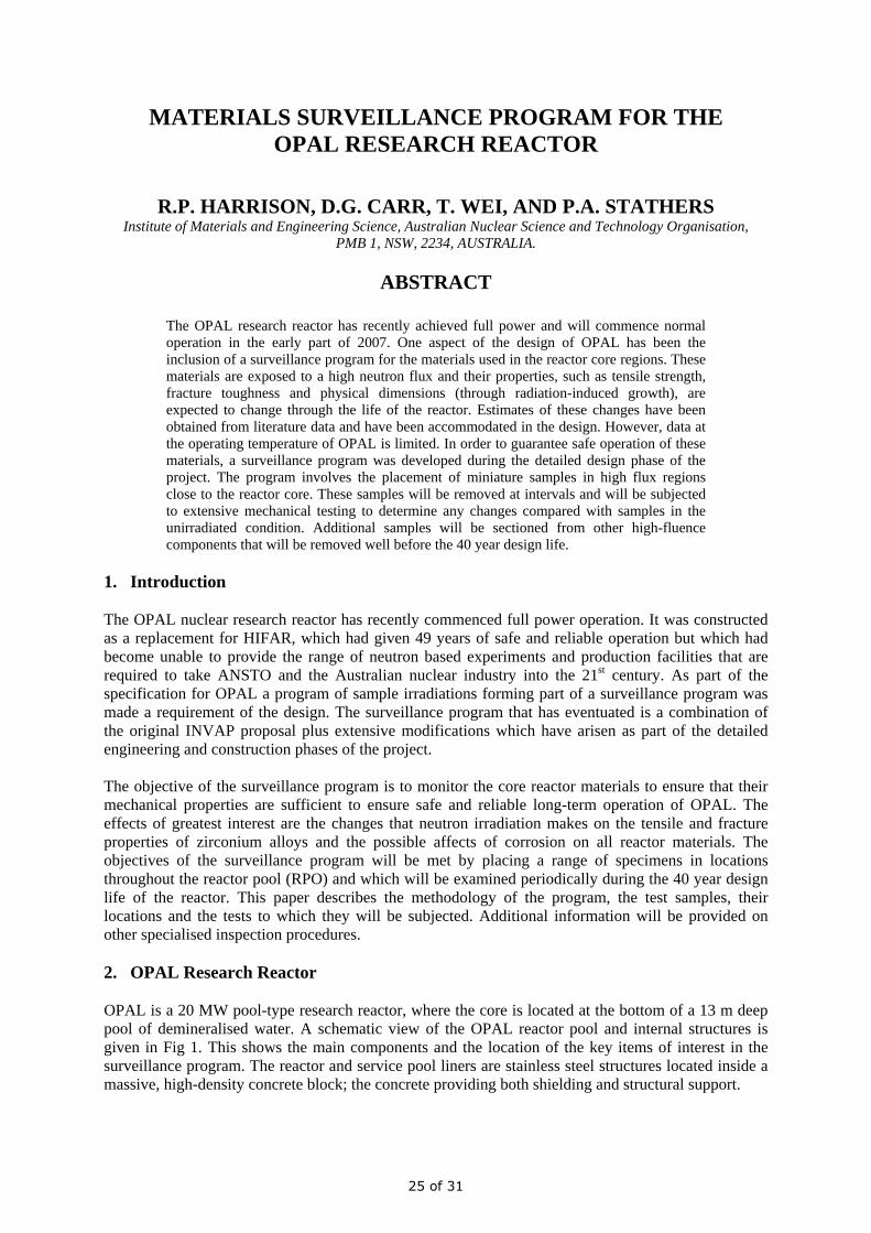
The reflector vessel (RVE) surrounds the core, providing both the core boundary (and path for the primary cooling water) and the volume of heavy water (D2O) that forms the reflector. It is a complex fully welded structure, with many through and re-entrant tubes providing access for irradiation facilities and beam tubes. Fig 1 shows the location of the RVE in the pool. It is a 2.6 m diameter cylinder with the core in a square-sectioned central region. Also shown in Fig 1 are the cold neutron source (CNS) and the associated vacuum containment (VC). The VC provides the barrier between the CNS moderator vessel (containing liquid D2 at ~18 K) and the core; an important safety feature of the design. The VC is 3 m long Zr-2.5Nb tube with the aluminium moderator vessel located inside.
Fig 1. A schematic of the OPAL research reactor. Components of interest in the surveillance program are the reactor pool liner and the reflector vessel (around the core). Also visible are the CNS moderator vessel at the bottom of the vacuum containment. 3. Surveillance Program Methodology The surveillance program is based on that described in ASTM E 185. This standard provides guidance for the setting up and operation of a surveillance program for light-water power reactors. The basic recommendations of this standard have been included in the surveillance program, however, changes have been made in a number of areas to reflect the lower level of risk associated with a research reactor compared with that of a power reactor. The objectives of the program are to monitor the changes in materials properties of components essential for the safe operation of the reactor. These changes include corrosion (principally the pool liner material), growth in zirconium alloys and changes in the tensile and fracture properties of all materials exposed to radiation. Each of these effects is considered below.
Reactor Pool Liner
Core
Reflector Vessel
Vacuum Containment CNS Moderator Vessel
26 of 31
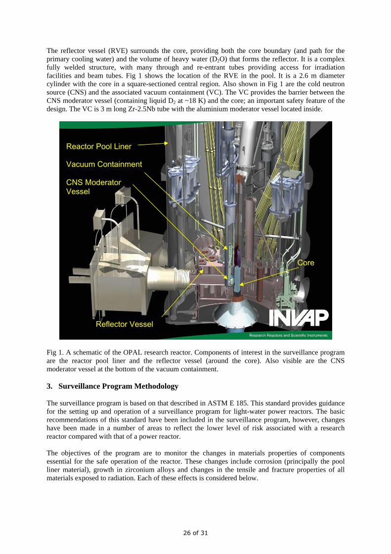
Corrosion resistance is clearly an important materials property for components designed to operate for 40 years or more. All the materials selected for OPAL have excellent corrosion resistance under the reactor’s operating conditions and problems are not expected. However, samples of dissimilar metal couples (Zircaloy-4/aluminium and 304L/aluminium) have been included in the program. Irradiation by neutrons causes an increase in tensile properties. The tensile properties of all the materials used will increase and samples of all materials are included in the program. Fracture toughness is expected to decrease for all the materials used. While a small decrease is acceptable, significant changes may invalidate the structural assessment performed in the design phase. A number of sample types will be used to obtain fracture data. Obtaining valid fracture toughness information for reasonably ductile materials is difficult, principally because of the sample size requirements for a valid assessment of toughness. A great deal of work has been undertaken over the past decade internationally on developing and validating small sample test methods that provide realistic values of toughness. A number of these will be used in the OPAL surveillance program, including the small punch (SP) test, the compact tension (CT) test and the sub-size Charpy test. These are described in the next section. 3.1 Sample Types Simple “dog-bone” tensile samples are used extensively as they are the simplest and can be made small without seriously affecting the validity of the results. They will provide information on the tensile properties and some information on ductility. However, they cannot provide information on fracture toughness. Three other sample types are used; small punch (SP), compact tension (CT) and the quarter-size Charpy. All these will provide information on fracture properties. The three main sample types used in the surveillance program are shown in Fig 2. The advantage of the SP sample is clear from a weight and activity perspective, being much smaller.
Fig 2. Photograph of the sample types used in the surveillance program. Of note is the small mass of the SP samples; important when testing radioactive materials. The SP test is a recent development and is at the stage of significant international application in a wide range of industries; details of the test can be found elsewhere [2]. In brief, the technique uses small disks of the material (in this work 6 mm diameter and 0.5 mm thick), through which a hardened steel
CT – mass 7.3 g Tensile – mass 2.2 g
Small Punch – mass 0.08 g
27 of 31
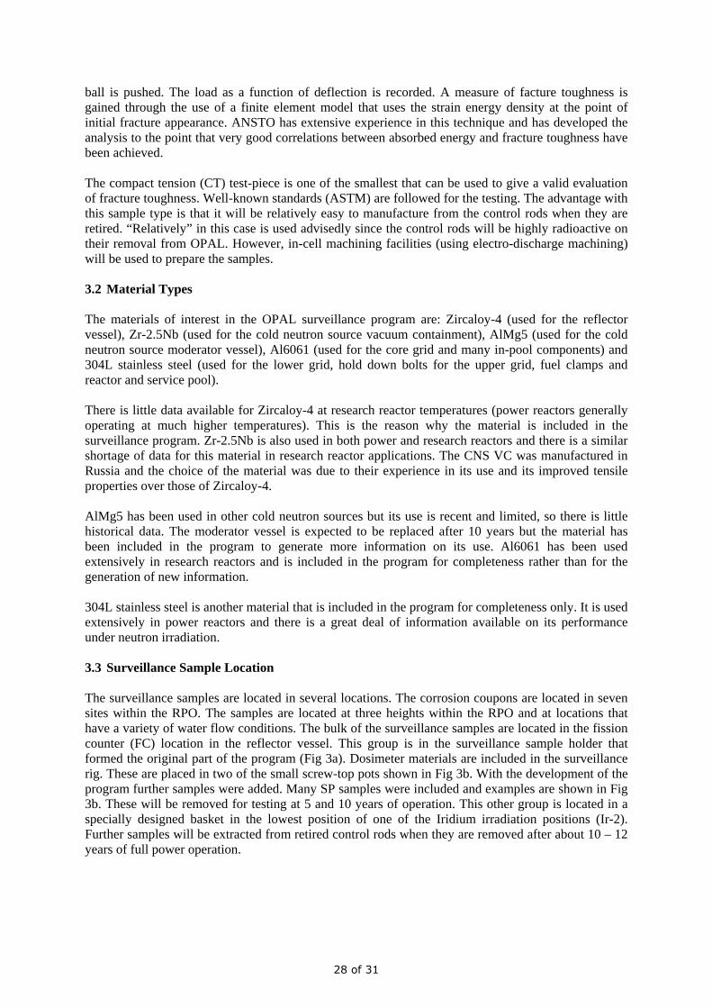
ball is pushed. The load as a function of deflection is recorded. A measure of facture toughness is gained through the use of a finite element model that uses the strain energy density at the point of initial fracture appearance. ANSTO has extensive experience in this technique and has developed the analysis to the point that very good correlations between absorbed energy and fracture toughness have been achieved. The compact tension (CT) test-piece is one of the smallest that can be used to give a valid evaluation of fracture toughness. Well-known standards (ASTM) are followed for the testing. The advantage with this sample type is that it will be relatively easy to manufacture from the control rods when they are retired. “Relatively” in this case is used advisedly since the control rods will be highly radioactive on their removal from OPAL. However, in-cell machining facilities (using electro-discharge machining) will be used to prepare the samples. 3.2 Material Types The materials of interest in the OPAL surveillance program are: Zircaloy-4 (used for the reflector vessel), Zr-2.5Nb (used for the cold neutron source vacuum containment), AlMg5 (used for the cold neutron source moderator vessel), Al6061 (used for the core grid and many in-pool components) and 304L stainless steel (used for the lower grid, hold down bolts for the upper grid, fuel clamps and reactor and service pool). There is little data available for Zircaloy-4 at research reactor temperatures (power reactors generally operating at much higher temperatures). This is the reason why the material is included in the surveillance program. Zr-2.5Nb is also used in both power and research reactors and there is a similar shortage of data for this material in research reactor applications. The CNS VC was manufactured in Russia and the choice of the material was due to their experience in its use and its improved tensile properties over those of Zircaloy-4. AlMg5 has been used in other cold neutron sources but its use is recent and limited, so there is little historical data. The moderator vessel is expected to be replaced after 10 years but the material has been included in the program to generate more information on its use. Al6061 has been used extensively in research reactors and is included in the program for completeness rather than for the generation of new information. 304L stainless steel is another material that is included in the program for completeness only. It is used extensively in power reactors and there is a great deal of information available on its performance under neutron irradiation. 3.3 Surveillance Sample Location The surveillance samples are located in several locations. The corrosion coupons are located in seven sites within the RPO. The samples are located at three heights within the RPO and at locations that have a variety of water flow conditions. The bulk of the surveillance samples are located in the fission counter (FC) location in the reflector vessel. This group is in the surveillance sample holder that formed the original part of the program (Fig 3a). Dosimeter materials are included in the surveillance rig. These are placed in two of the small screw-top pots shown in Fig 3b. With the development of the program further samples were added. Many SP samples were included and examples are shown in Fig 3b. These will be removed for testing at 5 and 10 years of operation. This other group is located in a specially designed basket in the lowest position of one of the Iridium irradiation positions (Ir-2). Further samples will be extracted from retired control rods when they are removed after about 10 – 12 years of full power operation.
28 of 31
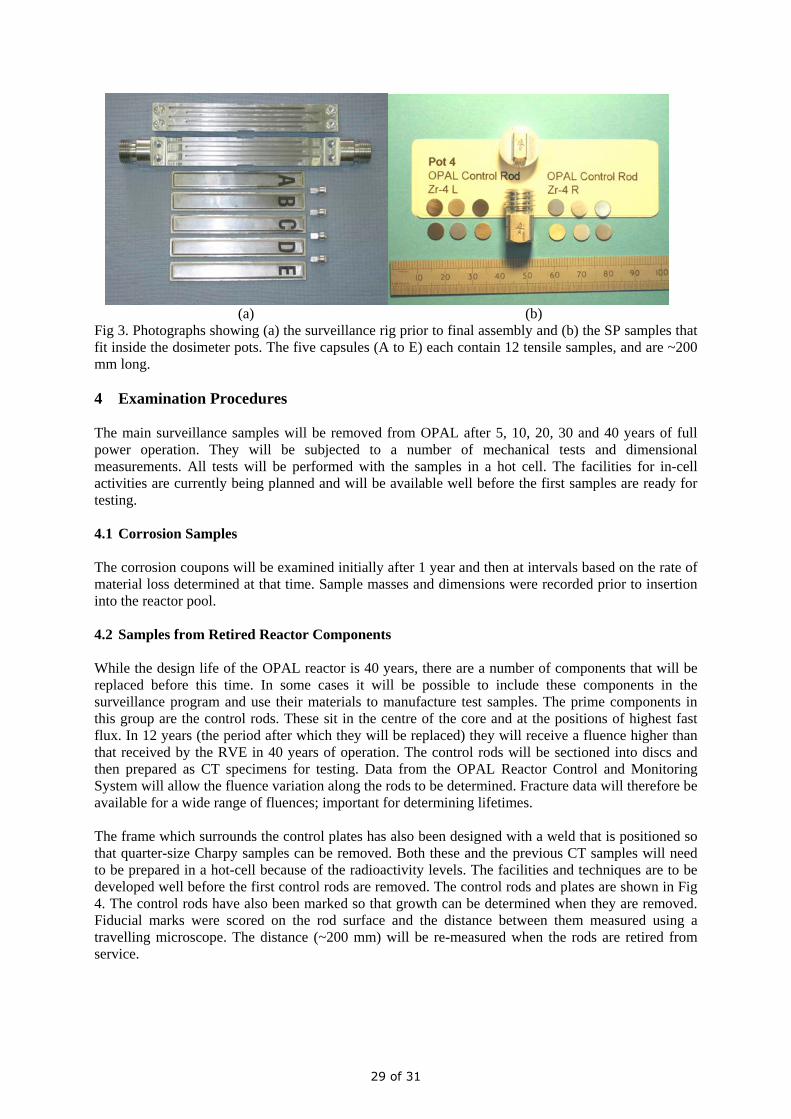
(a) (b) Fig 3. Photographs showing (a) the surveillance rig prior to final assembly and (b) the SP samples that fit inside the dosimeter pots. The five capsules (A to E) each contain 12 tensile samples, and are ~200 mm long.
4 Examination Procedures The main surveillance samples will be removed from OPAL after 5, 10, 20, 30 and 40 years of full power operation. They will be subjected to a number of mechanical tests and dimensional measurements. All tests will be performed with the samples in a hot cell. The facilities for in-cell activities are currently being planned and will be available well before the first samples are ready for testing. 4.1 Corrosion Samples The corrosion coupons will be examined initially after 1 year and then at intervals based on the rate of material loss determined at that time. Sample masses and dimensions were recorded prior to insertion into the reactor pool. 4.2 Samples from Retired Reactor Components While the design life of the OPAL reactor is 40 years, there are a number of components that will be replaced before this time. In some cases it will be possible to include these components in the surveillance program and use their materials to manufacture test samples. The prime components in this group are the control rods. These sit in the centre of the core and at the positions of highest fast flux. In 12 years (the period after which they will be replaced) they will receive a fluence higher than that received by the RVE in 40 years of operation. The control rods will be sectioned into discs and then prepared as CT specimens for testing. Data from the OPAL Reactor Control and Monitoring System will allow the fluence variation along the rods to be determined. Fracture data will therefore be available for a wide range of fluences; important for determining lifetimes. The frame which surrounds the control plates has also been designed with a weld that is positioned so that quarter-size Charpy samples can be removed. Both these and the previous CT samples will need to be prepared in a hot-cell because of the radioactivity levels. The facilities and techniques are to be developed well before the first control rods are removed. The control rods and plates are shown in Fig 4. The control rods have also been marked so that growth can be determined when they are removed. Fiducial marks were scored on the rod surface and the distance between them measured using a travelling microscope. The distance (~200 mm) will be re-measured when the rods are retired from service.
29 of 31
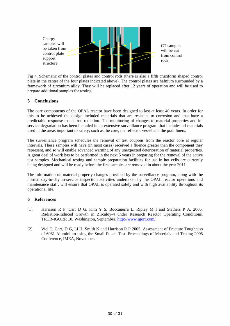
Fig 4. Schematic of the control plates and control rods (there is also a fifth cruciform shaped control plate in the centre of the four plates indicated above). The control plates are hafnium surrounded by a framework of zirconium alloy. They will be replaced after 12 years of operation and will be used to prepare additional samples for testing. 5 Conclusions The core components of the OPAL reactor have been designed to last at least 40 years. In order for this to be achieved the design included materials that are resistant to corrosion and that have a predictable response to neutron radiation. The monitoring of changes to material properties and in-service degradation has been included in an extensive surveillance program that includes all materials used in the areas important to safety; such as the core, the reflector vessel and the pool liners. The surveillance program schedules the removal of test coupons from the reactor core at regular intervals. These samples will have (in most cases) received a fluence greater than the component they represent, and so will enable advanced warning of any unexpected deterioration of material properties. A great deal of work has to be performed in the next 5 years in preparing for the removal of the active test samples. Mechanical testing and sample preparation facilities for use in hot cells are currently being designed and will be ready before the first samples are removed in about the year 2011. The information on material property changes provided by the surveillance program, along with the normal day-to-day in-service inspection activities undertaken by the OPAL reactor operations and maintenance staff, will ensure that OPAL is operated safely and with high availability throughout its operational life. 6 References [1]. Harrison R P, Carr D G, Kim Y S, Boccanerra L, Ripley M I and Stathers P A, 2005.
Radiation-Induced Growth in Zircaloy-4 under Research Reactor Operating Conditions. TRTR-IGORR 10, Washington, September. http://www.igorr.com/
[2] Wei T, Carr, D G, Li H, Smith K and Harrison R P 2005. Assessment of Fracture Toughness
of 6061 Aluminium using the Small Punch Test. Proceedings of Materials and Testing 2005 Conference, IMEA, November.
Charpy samples will be taken from control plate support structure
CT samples will be cut from control rods
30 of 31

European Nuclear Society Rue de la Loi 57
1040 Brussels, Belgium Telephone +32 2 505 30 54
Fax + 32 2 502 39 02 [email protected]
www.euronuclear.org
Layout and Design: Marion Brünglinghaus, ENS


![CRYOGENIC BATCH REACTOR OPTIMISATION [Read-Only]](https://img.pdfslide.us/doc/110x75/61b2b664985b394c8359e244/cryogenic-batch-reactor-optimisation-read-only.jpg)