Embed Size (px)
Citation preview

National Aeronautics and Space Administration
2012 SPIE Smart Structures/NDE Conference, March 11-15, San Diego, CA Embedded Sensing In Blades 1
Optimal topology and experimental evaluation of PE materials for
actively shunted GE polymer matrix fiber composite blades
Benjamin Choi
NASA Glenn Research Center
Kirsten Duffy
The University of Toledo
Jeffrey Kauffman
The Pennsylvania State University
Nicholas Kray
GE Aviation
https://ntrs.nasa.gov/search.jsp?R=20150010389 2020-06-15T16:48:34+00:00Z

National Aeronautics and Space Administration
2
1. Introduction and literature survey
2. Passive shunt damping
3. Digital shunt control design and simulation results
4. Experimental evaluation of PE materials
5. Optimal topology for spin test
6. Spin test in GRC’s Dynamic Spin Rig
7. Summary and future works
Objective
Investigate the feasibility of using piezoelectric sensors/actuators for
subscale GEnx composite fan blade damping at target modes.
Outline
2012 SPIE Smart Structures/NDE Conference, March 11-15, San Diego, CA Embedded Sensing In Blades

National Aeronautics and Space Administration
3
Previous Activities at GRC
1. Introduction
• Investigated several damping technologies to reduce excessive vibratory stresses
that lead to high cycle fatigue (HCF) failures in aircraft engine turbomachinery.
• Developed viscoelastic damping, passive impact damping, plasma sprayed
damping coating, and high temperature shape memory alloy (HTSMA).
• Demonstrated RC shunt damping of Ti-alloyed flat plates in GRC’s Dynamic Spin
Rig (K. Duffy and A. Provenza).
• Developed a digital shunt control that replaces equivalent passive-shunt analog
circuits with a digital code. (B. Choi).
• In collaboration with MESA, developed a prototype of power transfer device that
transmits control power to the PE actuators in the rotating frame (C. Morrison).
• Developed an FEM model to predict the system performance (J. Min).
Current Efforts at GRC
Develop a new damping technology for composite fan blades for future aircraft design in support of a Space Act Agreement with GE and as part of SFW project.
Proposed piezoelectric blade damping as a means of reducing engine blade vibration to support part of the project’s goals.
2012 SPIE Smart Structures/NDE Conference, March 11-15, San Diego, CA Embedded Sensing In Blades

National Aeronautics and Space Administration
4
Smart Fan Blade Technology Pros and Cons
Benefits/Payoffs: support the NASA missions
- Thinner and more efficient blades with shunt damping – fuel burn reduction, noise reduction, HCF failure reduction, etc.
- Actively controlled blades - real-time health monitoring, aeroelastic control, mistuning problem, active fan distortion control for distributed propulsion system, etc.
Drawbacks: structural characteristics degradation, durability and safety issues, added electronics weights, etc.
- S. Mall (2002) investigated the integrity of the embedded active PZT sensor/actuator under monotonic and fatigue loads.
- R. Pickering and K. Barlow (2007) specified the duration (10e+07 cycles) for each vibration mode for durability spin test.
- Completed a preliminary durability bench test for 109 cycles under 4.6g at target frequency. Need retest at high speed rotor.
- On-going system trade study of blade weights reduction vs. added electronics weights.
2012 SPIE Smart Structures/NDE Conference, March 11-15, San Diego, CA Embedded Sensing In Blades
Introduction (continued)

National Aeronautics and Space Administration
5
Analog Shunt Circuits 1.
Recent Advances in Turbomachinery Applications
• Passive control of turbomachine blading flow-induced vibrations (C. Cross, 2002).
• Passive shunt circuit was tested for piezoblade damping (S. Livet, 2008).
• Numerous papers published for passive shunt for rotorcraft vibration control.
Most of them used a synthetic (or virtual) inductor that consists of op amps, resistors,
capacitors, and ext. power supply
2. Active Control using Conventional PD Control Law
• Cascade flutter control using PE device in subsonic flow (T. Watanabe, 2005).
• Low-speed fan noise control using PE actuators mounted on stator vanes (P.
Remington, 2003).
Full-scale helicopter smart blade
in a Ames Res. Ctr. wind tunnel
• Force excitation control using surface-mounted PE
patches on the rotating blades (I. Santos, 2009).
- First demo in the spin pit.
• NASA Ames/Boeing developed shape-shifting helicopter
blades (2009). PE actuators created a mechanical motion
that moves a flap up and down.
Obviated a controversial issue concerning the use of PE.
Motivated us to continue the high-speed fan blade
damping.
2012 SPIE Smart Structures/NDE Conference, March 11-15, San Diego, CA Embedded Sensing In Blades
Introduction (continued)

National Aeronautics and Space Administration
2012 SPIE Smart Structures/NDE Conference, March 11-15, San Diego, CA Embedded Sensing In Blades
Problems Using Conventional Methods
1) Analog circuits may not be viable for the rotating engine blades.
- Impossible to accommodate the analog circuit size in the limited space
- Possible to have the risk of rotor imbalance at high centrifugal loads
- Hard to implement adaptive feature to follow changes in the blade’s natural
frequency
2) Active control using PD algorithm is not effective for resonant damping.
Introduction (continued)
6

National Aeronautics and Space Administration
7
1. Active Shunt Control
2012 SPIE Smart Structures/NDE Conference, March 11-15, San Diego, CA Embedded Sensing In Blades
Introduction (continued)
Replaces equivalent passive-shunt analog circuits with a digital code.
Generates a real-time adaptive controller tuning to the changing condition
of dynamic spin testing.
Can be effective for multi-mode control because a few coding lines are
necessary, as opposed to analog circuit approach.
In this presentation
2. Optimal Patch Selection
Being tested/selected the best performing piezoelectric patches from several
commercially available off-the-shelf piezoelectric materials.
3. Optimal Topology for GEnx Composite Blade
4. Initial Spin Test Result

National Aeronautics and Space Administration
8
General feedback control
RLC network.
Zo output Zi input
LiRZo
)/( CiLiRZi
1
)(
)/(
2
CRsLCs
LsRCs
CiLiR
LiR
Z
Z
V
V
i
o
i
o
Expressed in terms of
passive circuit
components (RLC),
regardless of modal
shape.
Transfer Function of Analog RLC Circuit
L
C
R
Kp: proportional gain, Ki: integral gain, Kd: derivative gain
TF of PID (proportional-integral-derivative) Control
2012 SPIE Smart Structures/NDE Conference, March 11-15, San Diego, CA Embedded Sensing In Blades
sKsKsKsKsKKsG ipddip /)(/)( 2
3. Digital Control Design

National Aeronautics and Space Administration
9
)()()()( sVsVsAsV isia
The actuator voltage Va(s) is
1
)()(
2
sCRCsL
sLRCssA
ii
iii
where Ai(s) is Σ
Vs(s)
F(d, s)
Va(s) Vi(s) +
- Gvv(s) Σ
+ +
Gfv(s)
Fig. 1. Feedback control block diagram for
blade structure with PEs.
)()(1
)(),(
)()(1
),(),(),(
sGsA
sVsrG
sGsA
sdFsrGsrY
vv
ivy
vv
fy
)()(1
)()(
)()(1
),()()(
sGsA
sVsG
sGsA
sdFsGsV
vv
ivv
vv
fv
s
)(
),()(,
),(
),(),(
)(
)()(,
),(
)()(
sV
srYsG
sdF
srYsrG
sV
sVsG
sdF
sVsG
a
vyfy
a
svv
afv
where
The Closed-loop System Transfer Functions
∑Ai(s)
A set of control laws in parallel
circuits can be summed to control
several modes (B. Choi, 2009).
Digital Control Design (continued)
2012 SPIE Smart Structures/NDE Conference, March 11-15, San Diego, CA Embedded Sensing In Blades

National Aeronautics and Space Administration
10
Digital Control Design (continued)
2012 SPIE Smart Structures/NDE Conference, March 11-15, San Diego, CA Embedded Sensing In Blades
Figure 2. Open-loop frequency response of (a) Gvv and (b) Gvy.
Figure 3. Open- and closed-loop frequency response of (a) Gvv and (b) Impulsive response of Gvv.
3.3 Simulation Results
Constructed a six-mode truncated mathematical model, assuming ωi and ζi

National Aeronautics and Space Administration
11 2012 SPIE Smart Structures/NDE Conference, March 11-15, San Diego, CA Embedded Sensing In Blades
How To Implement Digital Control On The Rotating Fan Blades
PE
Sensor signal
Op-Amp 1
± 200 VDC
50 mA
Rotating frame
Stationary frame A/D
Control
laws
D/A
Telemetry
system
(option)
Op-Amp n
Power
supply
Health
monitoring
(option)
Photo courtesy of Datatel Telemetry
Inductively powered transmitter
Photo courtesy of Datatel Telemetry NASA GRC/MESA prototype
control board w/ telemetry sys
Contains 8 inputs and 8 outputs, 8 Op-Amps (±200VDC @ 50mA), transmitter, and
receiver. D/A card weighs about 0.3 lbs excluding its heat sink & supporting Aluminum
block (0.2 lbs). A/D card weighs little less than 0.3 lbs.
Adding more features into the controller block, its application will be further extended
to health monitoring, aeroelastic control, mistuning problem, etc.
Time lag of 1.5ms each path across the gap (“latency” in wireless transfer) makes
difficult to move the controller to the stationary frame for the spin test purpose.
NASA GRC/MESA Control and Telemetry System
Wireless
transfer
(option)
National Aeronautics and Space Administration
12
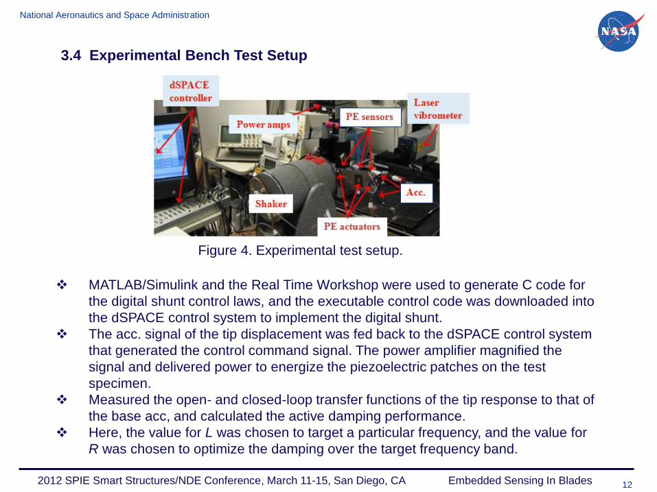
MATLAB/Simulink and the Real Time Workshop were used to generate C code for
the digital shunt control laws, and the executable control code was downloaded into
the dSPACE control system to implement the digital shunt.
The acc. signal of the tip displacement was fed back to the dSPACE control system
that generated the control command signal. The power amplifier magnified the
signal and delivered power to energize the piezoelectric patches on the test
specimen.
Measured the open- and closed-loop transfer functions of the tip response to that of
the base acc, and calculated the active damping performance.
Here, the value for L was chosen to target a particular frequency, and the value for
R was chosen to optimize the damping over the target frequency band.
2012 SPIE Smart Structures/NDE Conference, March 11-15, San Diego, CA Embedded Sensing In Blades
3.4 Experimental Bench Test Setup
Figure 4. Experimental test setup.

National Aeronautics and Space Administration
13 2012 SPIE Smart Structures/NDE Conference, March 11-15, San Diego, CA Embedded Sensing In Blades
4. Experimental Evaluation of PE Materials
Table 1. Material properties of piezoelectric patches.
Investigate the ability, and effectiveness of using PE materials to damp
resonant vibrations of GE-made composite coupons.
Determine which type of PE patch generates the best performance in terms
of damping and control power consumption.
PE patches were tested on the two polymer matrix fiber composite (PMFC)
coupons: narrow and wide cantilever composite beams.
Narrow beam: 9.5” x 1.3” x 0.25”; Wide beam: 9.5” x 2.0” x 0.25”

National Aeronautics and Space Administration
14 2012 SPIE Smart Structures/NDE Conference, March 11-15, San Diego, CA Embedded Sensing In Blades 14 2012 SPIE Smart Structures/NDE Conference, March 11-15, San Diego, CA Embedded Sensing In Blades
Experimental Evaluation of PE Material (continued)
Begun bench testing the Advanced Cerametrics d33-type vs. S-M d33-type
Targeted the 1st bending mode around 162.5 Hz.
Generated a swept sine signal that was used to excite the beam through the
target mode, and measured open- and closed-loop transfer functions.
Figure 5. Bode plot of transfer functions around 1st bending mode
With the same controller setup, the A-C d33-type patch produced ∆ζ = 0.0185,
while the Smart Material d33-type produced ∆ζ = 0.009.

National Aeronautics and Space Administration
15 2012 SPIE Smart Structures/NDE Conference, March 11-15, San Diego, CA Embedded Sensing In Blades 15 2012 SPIE Smart Structures/NDE Conference, March 11-15, San Diego, CA Embedded Sensing In Blades
Experimental Evaluation of PE Material (continued)
Another factor in determining the best performing patch candidate, is the
required control power consumption for the added damping performance
Figure 6. Control power consumption plots of using (a) S-M and (b) A-C
A-C d33 type patch, consumed 0.185 W to perform ∆ζ = 0.0185, while the S-
M d33-type consumed 0.93 W to perform ∆ζ = 0.009.
A-C actuator capability outperformed the S-M patch in terms of the damping
and associated power efficiency.

National Aeronautics and Space Administration
16 2012 SPIE Smart Structures/NDE Conference, March 11-15, San Diego, CA Embedded Sensing In Blades 16 2012 SPIE Smart Structures/NDE Conference, March 11-15, San Diego, CA Embedded Sensing In Blades
Experimental Evaluation of PE Material (continued)
Table 2. Active damping increase results using different type piezoelectric patches.
Similarly, all other type patches were tested on the same narrow and/or other
wide beams. All test results are summarized at Table 2.
The best performing patch was the A-C d33-type, but the correct size patch
was not available.
Thus, the second best S-M d31-type was selected for the subscale GEnx
blade damping work.

National Aeronautics and Space Administration
17 2012 SPIE Smart Structures/NDE Conference, March 11-15, San Diego, CA Embedded Sensing In Blades 17 2012 SPIE Smart Structures/NDE Conference, March 11-15, San Diego, CA Embedded Sensing In Blades 17 2012 SPIE Smart Structures/NDE Conference, March 11-15, San Diego, CA Embedded Sensing In Blades
4.3 Non-rotating Testing of Subscale GEnx Blade
Determine the actuation, sensing, and vibration damping capabilities of the S-M d31-
type patches.
Obtain the modal stress of the target 1st bending mode at 0 rpm.
Surface mount because the blade thickness was too small to contain the patches.
Decide on which side of the blade the PE actuator patch must be placed for
better damping.
Carry out several exp. tests to identify the optimal actuator and sensor patch
configuration because no comprehensive FEM model of the GEnx blade
with surface-mounted PEs was developed.
Figure 7. FEM analysis showing optimal patch locations for the target 1st bending mode.

National Aeronautics and Space Administration
18 2012 SPIE Smart Structures/NDE Conference, March 11-15, San Diego, CA Embedded Sensing In Blades 18 2012 SPIE Smart Structures/NDE Conference, March 11-15, San Diego, CA Embedded Sensing In Blades 18 2012 SPIE Smart Structures/NDE Conference, March 11-15, San Diego, CA Embedded Sensing In Blades
Begun Test 1, where a S-M actuator (PE A) is placed on the convex side,
and another S-M sensor patch (PE B) is placed on the concave side.
Used additional acc. Signal feedback to confirm the accuracy and validity of
the sensor patch functionality.
Non-rotating Testing of Subscale GEnx Blade (continued)
Figure 9. Bode plot of transfer functions around 1st bending mode for the Test 1.
TFPEB-base, was
taken, and ∆ζ =
0.009.
For comparison
purpose, TFtip-base,
was taken, and ∆ζ
= 0.009.

National Aeronautics and Space Administration
19 2012 SPIE Smart Structures/NDE Conference, March 11-15, San Diego, CA Embedded Sensing In Blades 19 2012 SPIE Smart Structures/NDE Conference, March 11-15, San Diego, CA Embedded Sensing In Blades 19 2012 SPIE Smart Structures/NDE Conference, March 11-15, San Diego, CA Embedded Sensing In Blades
Similarly, all other configurations were tested and evaluated by the blade tip
damping and the PE sensor strain reduction.
All exp. Resting results are summarized at Table 3.
Non-rotating Testing of Subscale GEnx Blade (continued)
Table 3. Exp. Results of increase in damping ratio using different patch configuration.
Test 4 produced the best damping performance of ∆ζ = 0.021 from the
TFtip_base, and ∆ζ = 0.019 from the TFPEB_base, respectively.
Thus, we decided to place the actuator patch on the concave side, and to
utilize a small sensing patch on the convex side for the ultimate goal of
dynamic spinning test.

National Aeronautics and Space Administration
20 2012 SPIE Smart Structures/NDE Conference, March 11-15, San Diego, CA Embedded Sensing In Blades 20 2012 SPIE Smart Structures/NDE Conference, March 11-15, San Diego, CA Embedded Sensing In Blades 20 2012 SPIE Smart Structures/NDE Conference, March 11-15, San Diego, CA Embedded Sensing In Blades 20 2012 SPIE Smart Structures/NDE Conference, March 11-15, San Diego, CA Embedded Sensing In Blades 20 2012 SPIE Smart Structures/NDE Conference, March 11-15, San Diego, CA Embedded Sensing In Blades 20 2012 SPIE Smart Structures/NDE Conference, March 11-15, San Diego, CA Embedded Sensing In Blades
5. Optimal Topology for Spin Test
Recent FEM analysis shows that the strain level on the convex side of the GEnx
blade exceeds the PE patch’s durable strain limit for high rotor speed.
Thus, the previous Test 4 configuration is no longer viable, and all PEs must be
located in the vicinity of the target placement on the concave side.
In this test setup, ∆ζ = 0.011 was achieved.
Figure 10. Actuator and sensor locations at the highest strain area. (b) Bode plot of TFTip_Base
5.1 Single patch configuration

National Aeronautics and Space Administration
21 2012 SPIE Smart Structures/NDE Conference, March 11-15, San Diego, CA Embedded Sensing In Blades 21 2012 SPIE Smart Structures/NDE Conference, March 11-15, San Diego, CA Embedded Sensing In Blades 21 2012 SPIE Smart Structures/NDE Conference, March 11-15, San Diego, CA Embedded Sensing In Blades 21 2012 SPIE Smart Structures/NDE Conference, March 11-15, San Diego, CA Embedded Sensing In Blades 21 2012 SPIE Smart Structures/NDE Conference, March 11-15, San Diego, CA Embedded Sensing In Blades 21 2012 SPIE Smart Structures/NDE Conference, March 11-15, San Diego, CA Embedded Sensing In Blades
A unique double patch configuration was proposed as one of the optimal topologies.
Two large actuator patches and one small sensor patch are placed around the high
modal strain location on the concave side.
The two large patches can be energized simultaneously to increase the actuating
power, or only one actuator can be used at a time, while the other can function as a
backup in the event of actuation patch failure
d31-type: 0.82 V-Amp to achieve ∆ζ = 0.014; d33-type: 1.34 V-Amp to achieve ∆ζ = 0.008.
Concluded that the optimal topology of the spin test is the double patch configuration
with two big S-M d31-type actuators and one small S-M d31-type sensor patch, all bonded
on the concave side.
Figure 11. (a) Two actuators and one sensor (b) Bode plot of transfer functions, TFPE31_Base,
around 1st bending mode, (c) Control power consumption.
5.2 Double patch configuration
Optimal Topology for Spin Test (continued)

National Aeronautics and Space Administration
22 2012 SPIE Smart Structures/NDE Conference, March 11-15, San Diego, CA Embedded Sensing In Blades 22 2012 SPIE Smart Structures/NDE Conference, March 11-15, San Diego, CA Embedded Sensing In Blades 22 2012 SPIE Smart Structures/NDE Conference, March 11-15, San Diego, CA Embedded Sensing In Blades 22 2012 SPIE Smart Structures/NDE Conference, March 11-15, San Diego, CA Embedded Sensing In Blades 22 2012 SPIE Smart Structures/NDE Conference, March 11-15, San Diego, CA Embedded Sensing In Blades 22 2012 SPIE Smart Structures/NDE Conference, March 11-15, San Diego, CA Embedded Sensing In Blades 22 2012 SPIE Smart Structures/NDE Conference, March 11-15, San Diego, CA Embedded Sensing In Blades 22 2012 SPIE Smart Structures/NDE Conference, March 11-15, San Diego, CA Embedded Sensing In Blades 22 2012 SPIE Smart Structures/NDE Conference, March 11-15, San Diego, CA Embedded Sensing In Blades
6. Spin Test Results
GE Aviation instrumented two test blades with the double patch configuration.
The two blades were fixed to a vertical rotor, and the rotor was placed in a vacuum
tank during operation.
Excitation was provided to the blades through the magnetic bearings that levitated
the rotor and blades in five axes.
As the shaft rotational speed changes, the blade’s natural frequencies will vary due
to centrifugal loads. Thus, an adaptive control feature was added to the closed-loop
controller using a lookup table method.
Figure 12. Blades in the GRC’s Dynamic Spin Rig.

National Aeronautics and Space Administration
23 2012 SPIE Smart Structures/NDE Conference, March 11-15, San Diego, CA Embedded Sensing In Blades 23 2012 SPIE Smart Structures/NDE Conference, March 11-15, San Diego, CA Embedded Sensing In Blades 23 2012 SPIE Smart Structures/NDE Conference, March 11-15, San Diego, CA Embedded Sensing In Blades 23 2012 SPIE Smart Structures/NDE Conference, March 11-15, San Diego, CA Embedded Sensing In Blades 23 2012 SPIE Smart Structures/NDE Conference, March 11-15, San Diego, CA Embedded Sensing In Blades 23 2012 SPIE Smart Structures/NDE Conference, March 11-15, San Diego, CA Embedded Sensing In Blades 23 2012 SPIE Smart Structures/NDE Conference, March 11-15, San Diego, CA Embedded Sensing In Blades 23 2012 SPIE Smart Structures/NDE Conference, March 11-15, San Diego, CA Embedded Sensing In Blades 23 2012 SPIE Smart Structures/NDE Conference, March 11-15, San Diego, CA Embedded Sensing In Blades
The blades have slightly different resonance frequencies, and coupling exists
between the blades through the rotor, resulting in each blade exhibiting two peaks.
The test was done using Blade 2 that has the higher response.
Figure 13. (a) First bending resonant peaks18 at 0 rpm, (b) Damping ratio for
baseline open circuit and actively controlled blades.
Spin Test Results (continued)
A more detailed discussion will be published in a subsequent paper18
Ran the spin test and measured open- and closed-loop transfer functions.
Achieved significant blade damping at 0 rpm, but the ability to damp decreased as
the rotor speed increased. Caused by the blade’s centrifugal stiffening and by the
peak modal strain location changing with the rotor speed.

National Aeronautics and Space Administration
24 2012 SPIE Smart Structures/NDE Conference, March 11-15, San Diego, CA Embedded Sensing In Blades 24 2012 SPIE Smart Structures/NDE Conference, March 11-15, San Diego, CA Embedded Sensing In Blades 24 2012 SPIE Smart Structures/NDE Conference, March 11-15, San Diego, CA Embedded Sensing In Blades 24 2012 SPIE Smart Structures/NDE Conference, March 11-15, San Diego, CA Embedded Sensing In Blades 24 2012 SPIE Smart Structures/NDE Conference, March 11-15, San Diego, CA Embedded Sensing In Blades 24 2012 SPIE Smart Structures/NDE Conference, March 11-15, San Diego, CA Embedded Sensing In Blades 24 2012 SPIE Smart Structures/NDE Conference, March 11-15, San Diego, CA Embedded Sensing In Blades
7. Conclusion
An active shunt control technique that emulated the tuned RLC circuit was
developed, enabling our team to accomplish a GRC Center milestone of
demonstrating blade damping in a spin test.
Several commercially available off-the-shelf piezoelectric materials were
tested through a series of the bench top tests. They were evaluated in terms
of damping capability and associated control power requirement, and the
Smart Material’s d31-type (S-M M2814-P2) was finally selected.
We finalized the optimal patch topology of the GEnx fan blade with the
double-patch configuration, where two identical S-M d31-type actuator
patches and one small S-M d31-type sensor patch were placed around the
high modal strain location on the concave (pressure) side.
Finally, successful spin testing up to 5,000 rpm was done in GRC’s Dynamic
Spin Rig. If damping is required over a particular speed range, the actuator
location(s) should be chosen based on high modal strain for that speed range
of interest.
There are definitely more challenging technical aspects that must be
considered, and more research must be accomplished before implementing
the piezoelectric damping control system.
However, this paper is an attempt at the initial task of proving the
feasibility of blade damping.