Embed Size (px)
Citation preview

Copyright © 2003 SAE International
ABSTRACT
An air-conditioner compressor-mounting bracket is astructural component of an engine, on which bolts attachan air-conditioner compressor. In this paper, the shapeof the air-conditioner compressor-mounting bracket of apassenger car is optimized using a finite elementsoftware, and the optimized bracket is manufactured andverified by tests. An objective function for the shapeoptimization of the bracket is the weight of the bracket.Two design constraints on the bracket are the firstresonant frequency of the compressor assembly and theneed not to fracture during the workbench durability test.The compressor assembly, which consists of acompressor, a bracket and connection bolts, is modeledusing finite elements. The bracket is modeled by solidelements and the swash-plate-type compressor isrepresented by rigid masses and beam elements inorder to consider the elastic effects of the compressor.For simulation of the dynamics stresses in the durabilitytest, the large mass method is used. The design variableis the shape of the bracket including thickness profiles ofthe front and back surfaces of the bracket, radius ofouter boltholes, and side edge profiles. The coordinatesof the FE nodes control the shape parameters. Optimalshapes of the bracket are obtained by using SOL200 ofMSC/NASTRAN. The verification tests are conducted onthe workbench and in a full vehicle. Test results showsthat the developed optimization procedure of the bracketare valid in the complex real world.
INTRODUCTION
Many peripheral pieces of equipment are attached on anengine block. Among them, the air-conditionercompressor is one of the largest components of thepowertrain in a passenger car. An air-conditionercompressor-mounting bracket is a structural component
of the engine, on which bolts attach the air-conditionercompressor. The compressor-mounting bracket supportsthe air-conditioner compressor and the dynamiccharacteristics of the compressor assembly mainlydepend on that of the bracket. The compressor-mounting bracket experiences severe dynamic loadsduring the engine operation because the bracket is fixedby bolts directly to the engine block. From a designer’sviewpoint, fatigue failure of the bracket should not occurduring the car’s life. Furthermore, resonant frequenciesof the compressor assembly should not exist in theengine-operation range because vibrations of thecompressor assembly can cause vibration and/or noiseproblems in the passenger compartment of the vehicle.
Nowadays, development of components using CAE toolssuch as the finite element method has been a commontool in early design stages [1,2]. In addition, the shapeand topology optimization technique is becoming auseful tool. In this paper, the shape of the air-conditionercompressor-mounting bracket of a passenger car isoptimized using commercial finite element software, andthe optimized results are confirmed by tests.
ANALYSIS OF THE BRACKET
The bracket is bolted on the engine block and other boltsconnect the air-conditioner compressor and the bracket.To operate the swash-plate-type compressor, the powerof the engine is transmitted through belts, which connectthe belt pulley of the compressor and crankshaft of theengine. In this study, the authors are interested in thedesign of the bracket and assume that the designs of thecompressor and engine block are fixed.
There are two major quantities to be analyzed in order todesign the compressor-mounting bracket. One is theresonant frequency of the compressor assembly and theother is the fatigue life of the bracket. First, the resonantfrequency of the compressor assembly is very important
2003-01-1667
Optimal Shape Design of an Air-Conditioner Compressor-Mounting Bracket in a Passenger Car
Doo-Ho Lee Dongeui University
Jeong-Woo Chang Halla Climate Control Corp.
Chan-Mook Kim Kookmin University

because the excitation frequency range of the engine isvery wide and the resonance of the compressorassembly in the excitation range will cause manyvibration and noise problems as well as fatigue fracture.To identify the resonant frequency of the compressorassembly in a supplier company, generally sine-sweepexcitation tests are fulfilled with a specified excitationlevel. To calculate the resonant frequencies of a bracketin an early design stage, a finite element model isnecessary. For the FE model, the engine block orexcitation jig is assumed to be rigid and solid elementsmodel the bracket in this study. The connection bolts arerepresented by equivalent elastic springs for eachdirection. The compressor consists of pistons,compression chambers, a rotary shaft, a clutch pad, anelectromagnet, a belt pulley and a shell. Figure 1 showsa schematic diagram of the compressor assembly. Thecompressor operates by rotation of the belt pulley whenthe electromagnet pulls the clutch pad. To represent thedynamic characteristics of the compressor, a detail FEmodeling or an experimental approach [3] is needed,however, this results in high computation costs in thedesign stage due to many design iterations. In this studya simplified compressor model is developed byidentifying characteristics of the compressor assemblyfrom tests. Figure 2 shows the response of acompressor assembly in the excitation test. FromFigures 1 & 2 it is shown that the clutch pad andcompressor axis affect very much the lowest resonantfrequency of the compressor assembly. From the testresults, the axis is modeled by beam elements and aconcentrated mass represents the clutch pad at the end
Table 1. Correlation results of the compressor assembly.
ModeNo EMA(Hz) FEA(Hz) Mode Shape Error
[%]
1 239 234 Lateral mode 2.1
2 - 255 Vertical mode -
3 328 318 Lateral mode 3.0
of the axis. The other structures of the compressor areconsidered as a rigid mass. Figure 3 shows a finiteelement model of the compressor assembly. The FEmodel of the compressor assembly is correlated with theresults of the experimental modal analysis (EMA). Theresonant frequencies of the compressor assemblyidentified by an impact hammer test and the FE modelare tabulated in Table 1. In addition, Figure 4 shows thefirst mode shapes obtained from the test and the FEanalysis, respectively. Table 1 and Figure 4 show thatthe developed FE model is valid for the compressorassembly.
Next, to identify the fatigue life of the bracket, a suppliercompany fulfills durabilty tests on a testbed. Thedurability tests consist of several excitation tests. Ashaker excites the compressor assembly in threedirections. The specification of the durability testregulates the time period and input acceleration level ofthe excitations as well as the excitation patterns. Thereare two excitation patterns in the durability specification:one is a sine-sweep over the frequency range and
Figure 1. A schematic diagram of the compressor assembly.
Figure 2. Accelerations on the compressor in an excitation test. Figure 4. Mode shape of the compressor assembly at the firstresonant frequency by test compare with that of FE analysis
0 100 200 300 400 5000
5
10
15
20
Clutch OFFClutch ON
Acc
eler
atio
n[g]
Frequency[Hz]
Figure 3. An FE model for the compressor assembly.
another is a fixed frequency excitation at the resonantfrequencies of the compressor assembly. Generally thefatigue damages are accumulated mostly in theresonant-point excitations. To estimate the fatigue life ofthe bracket in the early design stage, dynamic stressanalyses are necessary for the durability test. For thedynamic stress analysis, we used the same FE model ofthe resonant frequency problem and applied the largemass method [4] in commercial software,MSC/NASTRAN. For the purpose of verifying the stressanalysis model, stresses of an existing bracket arecalculated and compared with those of a measured oneduring the durability test. Figure 5 shows a test set-up tomeasure strains using the strain gauge. Figure 6 showsa comparison result of a selected point. In Figure 6, ameasured strain is compared with the calculated strainsat every node located within a hemisphere the diameterof which is equal to the length of the strain gaugebecause the measured strain represents an averagedvalue due to the finite magnitude of the strain gauge. It isshown in Figure 6 that the FE model represents thestress state of the bracket during the durability test.
SHAPE OPTIMIZATION OF THE BRACKET
The air-conditioner mounting bracket should have infinitefatigue life as well as light mass for fuel economy andminimum manufacturing cost. To insure the fatigue life acompany has not only durability test specifications onthe workbench but also a guide for the lower bound ofthe resonant frequency of the compressor assembly. To
optimize the shape of a bracket, an optimization problemshould be defined in standard form as follows:
n,1,i,)(gtoSubject
)f(Minimize
thatsuchΩshapetheFind
i L=≤ΩΩ
0
(1)
Here, f is the objective function and ig is i-th inequalityconstraint.
The authors select the weight of the bracket as anobjective function because the material cost occupies alarge portion of the total cost of production especially atthe component level. In addition, minimization of themass enhances fuel economy of the passenger car. Theweight of the bracket can be calculated by summation ofelement weights as:
∑∫=Ω
==NE
iEi
1
VρdVf ρ (2)
where EiV is the volume of i-th element, ρ the density,and NE is the number of elements.
As a constraint of the shape optimization problem, thelowest resonant frequency of the compressor assemblyshould exceed a prescribed value. This constraint canbe expressed as:
010
1 ≤−=ωω
1g (3)
where 1ω is the first resonant frequency and 0ω is theprescribed value. Another constraint in the problem isthat it must not fracture during the durability workbenchtest. Fatigue life can be estimated by accumulatingdamage using the Miner’s rule [5]. However, it is notedthat in the durability test, most of the damage come fromthe resonant point excitation, which means the fatiguelife of the overall test can be approximated by that of theresonant point excitation test. For a conservative design,the authors impose the infinite-life constraint on theresonant excitation. As a result, the constraints on thefatigue life is converted to stress constraints such as:
Figure 7. Initial design of the bracket for shape optimization
Figure 5. A test set-up to measure dynamic strains
Figure 6. A calculated strain compared to the measured one
m,1,j,g2 L=≤−=∞
01σσ j
(4)
where jσ is the Von-Mises stress of j-th node, ∞σ isthe fatigue strength and m is the total number of nodes.
A current-design (CD) bracket for a passenger car isselected as a target bracket to be optimized. The air-conditioner compressor-mounting bracket is equipped onan inline four-cylinder engine and is made by castingaluminum. Similar to the current design, an initial shapefor the optimization is selected as shown in Figure 7.The bracket is modeled by 2393 solid elements and3621 nodes. The design variable of the problem is theshape of the bracket. Here, the shape of the upper andlower surfaces, the radius of the outer bolthole 6, andthe shape of the Side2 surface in Figure 7 are selectedas the design variables. The shapes selected as thedesign variables are controlled by the position of thenodes. For the upper, lower, and the Side2 surfaces,every node on the surfaces controls the surface shapesby movements perpendicular to each surface. InternalFE nodes move proportionally to the surface movementsof the design variable nodes. The number of the designvariables is 1072 for the bracket problem.
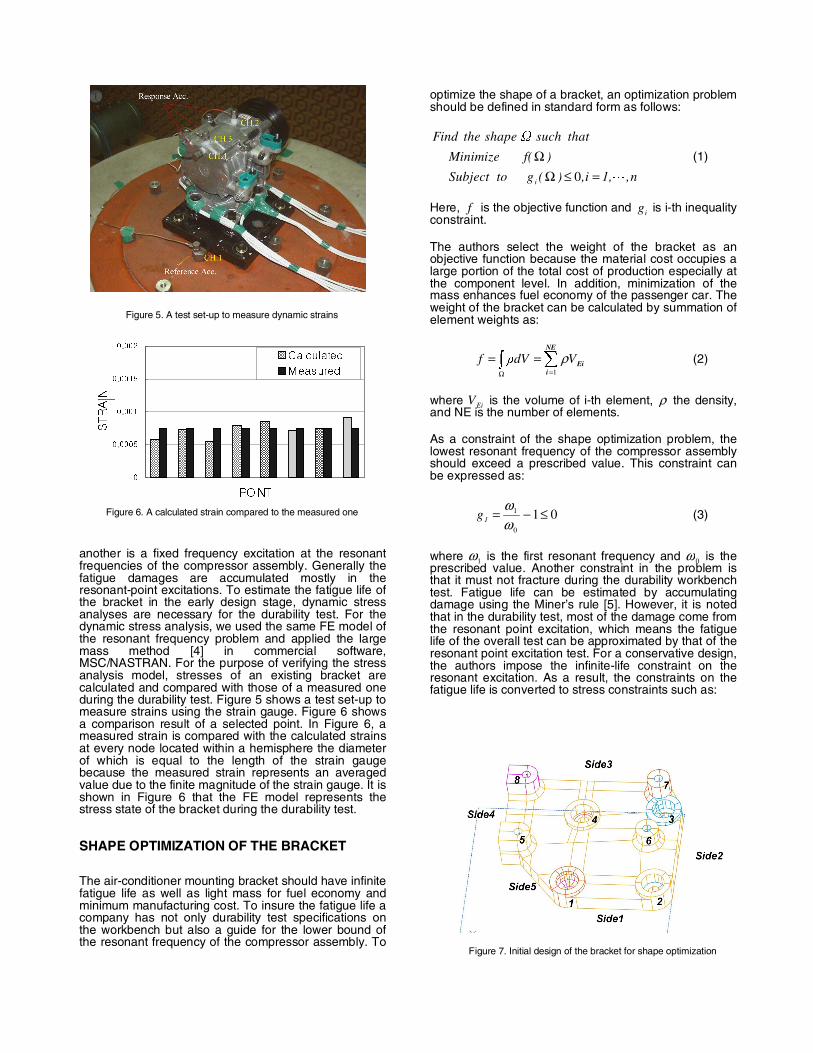
The shape optimization problem is solved by SOL200 ofMSC/NASTRAN. Here, two cases are examined whichhave identical formulation except the prescribedresonant-frequency constraint value, 0ω . Table 1summarizes the results. It is noted that CASE 2 doesnot satisfy the resonant frequency constraint at the initial
Table 2. The shape optimization results of the bracketproblem
Initial CASE1 CASE2
1ω (Hz) 241.7 241.6 249.1
0ω (Hz) - 240 250
f (Kg) 1.04 0.617 0.915
No. of Iter. - 28 5
Figure 8. The shape optimization results of the bracket
(b) Case 2
(a) Case 1
Figure 9. Stress contours of the bracket
(a)Initial design
(b) Optimized design
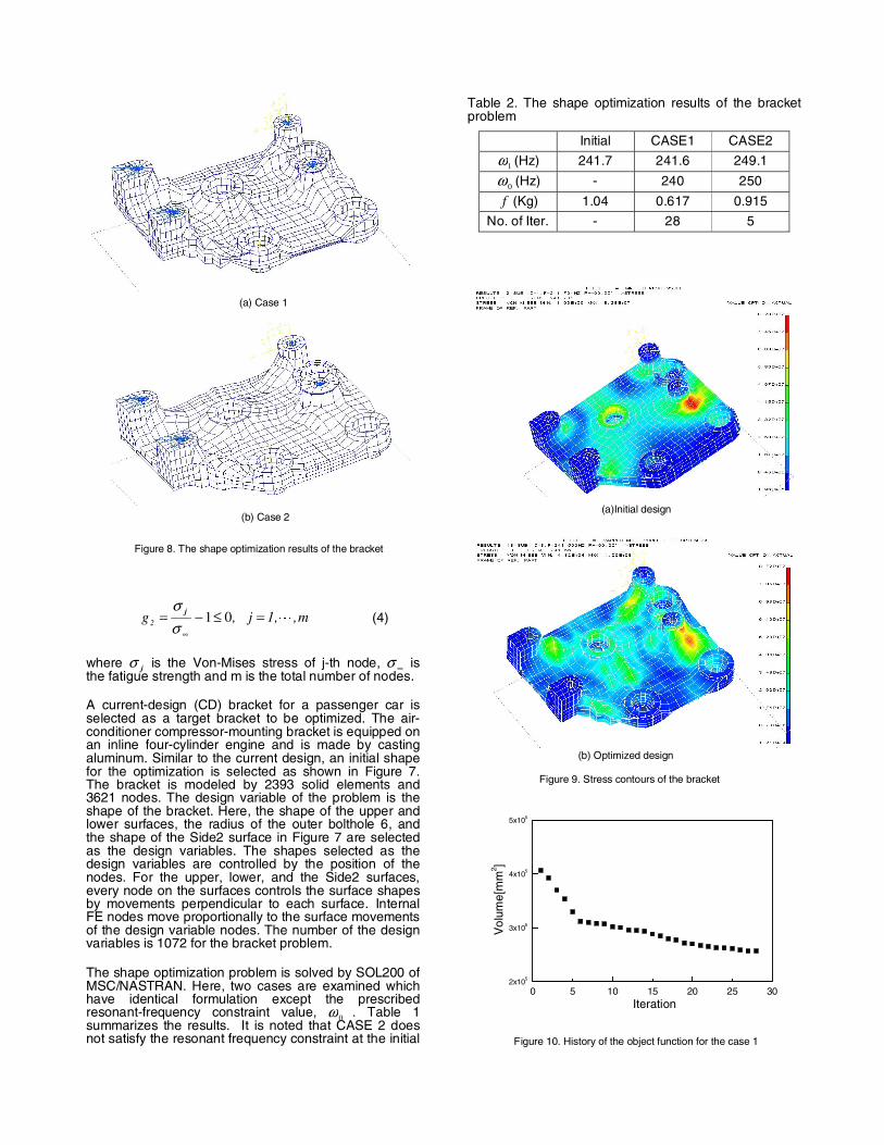
Figure 10. History of the object function for the case 1
0 5 10 15 20 25 302x105
3x10⁵
4x10⁵
5x10⁵
Vol
ume[
mm
2 ]
Iteration
design. Figure 8 shows the optimized shapes for eachcase.Figure 9 shows stress contours of the initial andthe optimized shapes for CASE 1. From the figures, it isshown that the highly stressed parts of the initial designare reinforced during the design iterations, andconversely the lower stressed parts are shrunken. Figure10 shows a history of the object function during designiterations for CASE 1.
The shape optimization problem of the bracket is a verylarge one, which has one thousand design variables andone modal analysis and three frequency responseanalyses. For an example, determining the results forCASE 1 took 9480 sec of cpu time in HP X2000Win2000 workstation with one 1.7 GHz Pentium 4processor, but more than two days in real elapsed time.Introducing control parameters of the surface patches asdesign variables will reduce the solving time of theoptimization problem. However, this may increase thetotal engineering time. Therefore, some trade-off isneeded in selecting the design variables.
PROTOTYPING AND VERIFICATIONS
Based on the optimization results of the previous section,a prototype bracket is manufactured and tested. Theoptimized shape of CASE 1 is selected as a prototypebecause CASE 1 has a lighter weight than the currentproduct but has a similar resonant frequency.
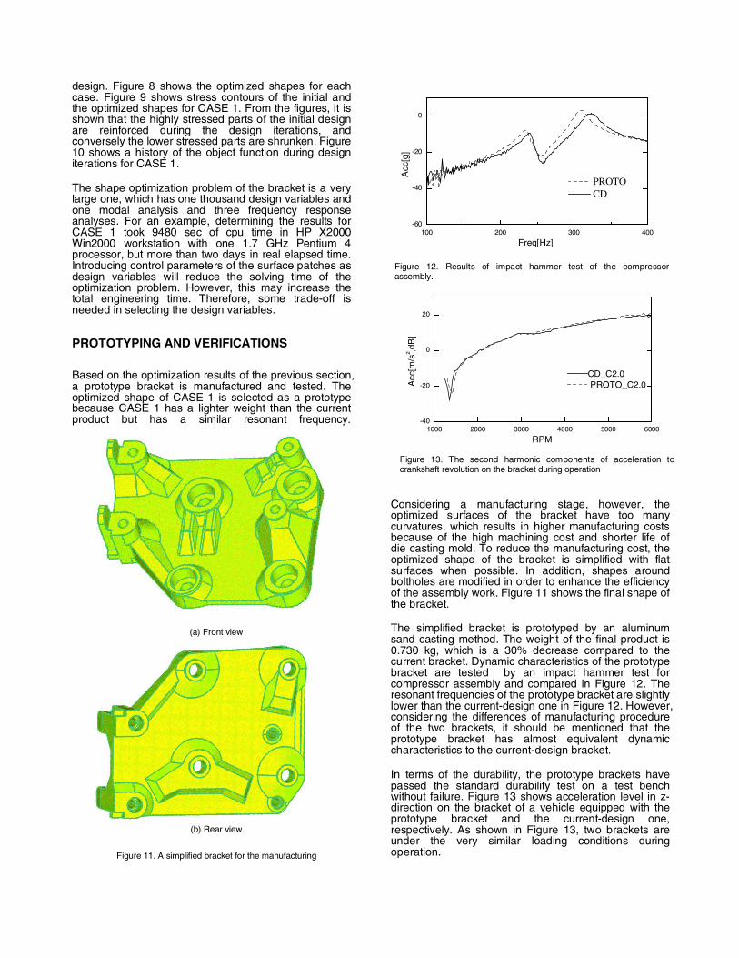
Considering a manufacturing stage, however, theoptimized surfaces of the bracket have too manycurvatures, which results in higher manufacturing costsbecause of the high machining cost and shorter life ofdie casting mold. To reduce the manufacturing cost, theoptimized shape of the bracket is simplified with flatsurfaces when possible. In addition, shapes aroundboltholes are modified in order to enhance the efficiencyof the assembly work. Figure 11 shows the final shape ofthe bracket.
The simplified bracket is prototyped by an aluminumsand casting method. The weight of the final product is0.730 kg, which is a 30% decrease compared to thecurrent bracket. Dynamic characteristics of the prototypebracket are tested by an impact hammer test forcompressor assembly and compared in Figure 12. Theresonant frequencies of the prototype bracket are slightlylower than the current-design one in Figure 12. However,considering the differences of manufacturing procedureof the two brackets, it should be mentioned that theprototype bracket has almost equivalent dynamiccharacteristics to the current-design bracket.
In terms of the durability, the prototype brackets havepassed the standard durability test on a test benchwithout failure. Figure 13 shows acceleration level in z-direction on the bracket of a vehicle equipped with theprototype bracket and the current-design one,respectively. As shown in Figure 13, two brackets areunder the very similar loading conditions duringoperation.
Figure 12. Results of impact hammer test of the compressorassembly.
Figure 11. A simplified bracket for the manufacturing
(b) Rear view
(a) Front view
Figure 13. The second harmonic components of acceleration tocrankshaft revolution on the bracket during operation
100 200 300 400-60
-40
-20
0
PROTOCD
Acc
[g]
Freq[Hz]
1000 2000 3000 4000 5000 6000-40
-20
0
20
CD_C2.0PROTO_C2.0A
cc[m
/s2 ,d
B]
RPM

To confirm performances of the prototype bracket,vehicle tests on noise and vibration are fulfilled. Fromthe vehicle tests, we can see that two brackets haveequivalent performance in vibration and noise level foreach operational mode. As an example, Figure 14shows acceleration levels on the prototype bracketduring operation compared to the those on the MPbracket.
CONCLUSION
The shape of the air-conditioner compressor-mountingbracket of a passenger car is optimized using a finiteelement software package, and the optimized results areverified by tests. The cost function is the weight of thebracket. The first resonant frequency and durability areconsidered as the design constraints. The constraints ondurability were transformed into the stress constraints.The bracket is modeled by solid elements and theswash-plate-type compressor is represented by rigidmasses and beam elements in order to consider theelastic effects of the compressor. The design variable isthe shape of the bracket such as the thickness profiles ofthe front and back surfaces of the bracket, radius of theouter boltholes and, the side edge profiles. The optimalshapes of the bracket are obtained by usingMSC/NASTRAN.
The optimized bracket is manufactured and verificationtests are fulfilled. The shape of the bracket is simplifiedto take manufacturing costs into consideration. Theverification tests are conducted on the workbench and inthe full vehicle. Test results shows that the developedoptimization procedure of the bracket are valid in thecomplex real world.
ACKNOWLEDGEMENTS
This research has been supported by Halla ClimateControl Corp. and the authors wish to expressappreciation.
REFERENCES
1. K. Ohta, Y. Sugiyama, H. Kawabe, Y. Kohtake, M. Narita,T. Keishi and M. Kaji, “Development of a Method toPredict Fatigue Failure Life of Junction Block BracketUsing CAE”, SAE Paper No. 2001-01-1099, 2001.
2. Murali M.R. Krishna, “ Finite Element Topography andShape Optimization of a Jounce Bumper Bracket”, SAEPaper No. 2002-01-1468, 2002.
3. T.S. Gong, C.M. Kim, D.H. Lee and S.Y. Seo, “DynamicStress Analysis of Structural Connection Using an FRF-based Substructuring Method”, Proceedings of the KSNVESpring Annual Conference, pp.1195~1201, 2002.
4. Ken Blakely, MSC/NASTRAN Basic Dynamic AnalysisUser’s Guide, The Macneal-Shcwendler Corporation.
5. R. I. Stephens, A. Fatemi, R.R. Stephens and H. O. Fuchs,Metal Fatigue in Engineering, John Wiley & Sons, Inc.,New York, 2001.
Figure 14. Acceleration levels on the bracket during operation
(a) At idle condition
(b) 80 km/h on flat road
0 100 200 300 400 500 600 700 800 900 1000
-80
-60
-40
-20
0 CDPROTO
Aut
opow
erS
pect
rum
[m2 /s
4 ,dB
]
Frequency[Hz]
0 100 200 300 400 500 600 700 800 900 1000
-80
-60
-40
-20
0 CDPROTO
Aut
opow
erS
pect
rum
[m2 /s
4 ,dB
]
Frequency[Hz]