Embed Size (px)
Citation preview
OPTIMAL PLACEMENT OF ACTUATORS
IN FIBER REINFORCED POLYMER
COMPOSITE SHELL STRUCTURES
USING GENETIC ALGORITHM
A THESIS SUBMITTED IN PARTIAL REQUIREMENTS FOR THE
DEGREE OF
Bachelor of Technology
In
Mechanical Engineering
By
ANJANA SATPATHY
Roll No. – 10503075
Department of Mechanical Engineering
National Institute of Technology, Rourkela
2009

2
National Institute of Technology
Rourkela
CERTIFICATE
This is to certify that this report entitled, “OPTIMAL PLACEMENT OF
ACTUATORS IN FIBER REINFORCED POLYMER COMPOSITE
SHELL STRUCTURES USING GENETIC ALGORITHM” submitted
by Anjana Satpathy in partial fulfillments for the requirements for the award
of Bachelor of Technology Degree in Mechanical Engineering at National
Institute of Technology, Rourkela (Deemed University) is an authentic work
carried out by her under my supervision and guidance.
To the best of my knowledge, the matter embodied in this
report has not been submitted to any other University / Institute for
the award of any Degree or Diploma
Date:
NIT Rourkela (Prof. T. Roy)
Dept. of Mechanical Engineering,
National Institute of Technology
Rourkela - 769008, Orissa

3
ACKNOWLEDGEMENT
I deem it a privilege to have been a student of Mechanical
Engineering stream in National Institute of Technology, Rourkela
I express my deep sense of gratitude and obligation to my project
guide Prof. T. Roy for his invaluable guidance and support. I am very
grateful to him for allowing me to do this project and for his constant help
and support throughout the making of this project.
Anjana Satpathy
Roll No. – 10503075
8th
Semester, B.TECH
Department of Mechanical Engineering
National Institute of Technology, Rourkela
4
ABSTRACT
Active vibration control of smart FRP composite structures finds use in high
performance structures especially in light weight composite structures.
Proper implementation of such smart structure systems demands complete
understanding of their responses, optimal placement of sensors and
actuators, and design of an appropriate control system. In the present work,
an improved genetic algorithm (GA) based optimal collocated sensors and
actuators of smart fiber reinforced polymer (FRP) composite shell structures
has been presented. Layered shell finite elements have been formulated and
the formulation has been validated for coupled electromechanical analysis of
curved smart FRP composite structures having piezoelectric sensors and
actuators patches. Modal analysis has been performed to transfer the coupled
finite element equation to state space equation. An integer-coded GA-based
open-loop procedure has been implemented for optimal placement of
actuators for maximizing controllability index. This type of GA with
uniform crossover and mutation technique has been developed to efficiently
search for optimal locations of sensors/actuators.In this project, we have
used integer coded GA to find optimal placement of actuators on spherical
shell structures and semi-circular ring.
5
CONTENTS
ABSTRACT 4
1. INTRODUCTION 8
1.1 Fiber Reinforced Polymer 11
2. LITERATURE REVIEW 13
2.1 Parameter Variation 13
2.2 Deterministic Methods 14
2.3Stochastic Methods 17
2.4 Motivation and Objectives 21
3. GA FOR OPTIMAL PLACEMENT OF ACTUATORS 23
3.1 Genetic Algorithm 23
3.2 Shell Finite Element 29
3.3 State Space Representation 31
3.4 GA for Optimal Placement 34
4. RESULTS AND DISCUSSION 37
4.1 Structural validation 37
4.2 Validation for optimal actuators placement 37
4.3 Optimal vibration control of a semi-circular ring 40
4.4 Optimal vibration control of laminated spherical shell panel 42
5. CONCLUSION AND SCOPE FOR FUTURE WORK 45
5.1 Conclusion 45
5.2 Scope for Future Work 45
6. REFERENCES 46
6
LIST OF FIGURES
1.Schematic representation of the basic elements of a Smart Structure 9
2. Figure representing Basic Genetic Algorithm 28
3. Smart layered shell element 29
4. Shell element with various coordinates system 30
5. Optimal location of four actuators on the beam substrate based
on maximum controllability 39
6. Comparison of variation of controllability index with generation
for the cantilever beam using integer- and binary-coded GA 40
7. Actuators location on the semicircular ring based on maximum
controllability index 41
8. Variation of controllability index with generation for semicircular
ring 41
9. Schematic Representation of a Spherical shell 43
10. Actuators location on the spherical panel based on
maximum controllability index. 43
11.Variation of controllability index with generation for spherical
panel 44
7
LIST OF TABLES
1. Material properties of structural laminate and PZT 38
2. Several important parameters for integer- and binary-coded GA 39
8
CHAPTER 1
INTRODUCTION
Active vibration control in distributed structures is of practical interest
because of the demanding requirement for guaranteed performance. This is
particularly important in light-weight structures as they generally have low
internal damping. An active vibration control system requires sensors,
actuators, and a controller. The design process of such a system
encompasses three main phases such as structural design, optimal placement
of sensors and actuators and controller design. In vibration suppression of
structures, locations of sensors and actuators have a major influence on the
performance of the control system. It is well known that misplaced sensors
and actuators lead to problems such as the lack of observability or
controllability. Active vibration control is defined as a technique in which
the vibration of a structure is reduced by applying counter force to the
structure that is appropriately out of phase but equal in force and amplitude
to the original vibration. As a result two opposing forces cancel each other,
and structure essentially stops vibrating. Techniques like use of springs,
pads, dampers, etc have been used previously in order to control vibrations.
These techniques are known as ‘Passive Vibration Control Techniques’.
They have limitations of versatility and can control the frequencies only
within a particular range of bandwidth. Hence there is a requirement for
‘Active Vibration Control’. ‘Active Vibration Control’ makes use of ‘Smart
Structures’. This system requires sensors, actuators, a source of power and a
compensator that performs well when vibration occurs. Smart Structures are
used in bridges, trusses, buildings, mechanical systems, space vehicles,
9
telescopes, and so on. The analysis of a basic structure can help improve the
performance of the structures under poor working conditions involving
vibrations. “A Smart Structure” means a structure that can sense an external
disturbance and respond to that with active control in real time to maintain
the mission requirements. A Smart Structure typically consists of a host
structure incorporated with sensors and actuators coordinated by a
controller. The integrated structured system is called Smart Structure
because it has the ability to perform self diagnosis and adapt to
environmental change. One promising application of such smart structure is
the control and suppression of unwanted structural vibrations. Fig. 1 depicts
the schematic representation of the basic elements of a smart structure
Fig. 1 Schematic representation of the basic elements of a Smart
Structure
• Sensor Patch
It is bonded to the host structure (Beam). It is generally made up of
piezoelectric crystals (one of the smartest materials). It senses the
disturbance of the beam and generates a charge which is directly
proportional to its strain. Direct piezoelectric effect is used here.
10
• Controller
The charge developed by the sensor is given to the controller. The controller
lines the charge according to suitable control gain and then the charge is fed
to the actuator. Controller also forms the feed back transfer function for this
system.
• Actuator Patch
The lined up charge from the controller is fed to the actuator. An actuator is
a piezoelectric patch bonded to the host. Due to the input voltage, actuator
causes pinching action (or generates shear force along the surface of the host
which acts as the damping force and helps in the attenuating vibration
motion of the beam. Converse piezoelectric effect is used here.
A given structure can vibrate with many modes. The design of controller for
all the modes is very difficult. However, all the modes do not contribute
significantly to the overall disturbance. Hence, we filter out the modes which
cause the maximum disturbance. Hence a controller can be designed to
control only these modes.
In this project we have used an improved integer coded GA along with
improved uniform crossover and mutation technique for determination of
optimal placement of sensors and actuators. Optimal placement of PZT
actuators on the curved smart FRP composite structures (i.e. semicircular
ring, spherical and ellipsoidal shell panel) have been studied based on the
controllability index, which is the singular value of the control input matrix.
Higher the controllability index, the lower will be the electrical potential
required for active control. Integer coded genetic algorithm has been applied
to efficiently find the maximum controllability index.
11
1.1 FIBER REINFORCED POLYMER
A Fiber Reinforced Polymer (FRP) composite is defined as a polymer
(plastic) matrix, either thermoset or thermoplastic, that is reinforced
(combined) with a fiber or other reinforcing material with a sufficient
aspect ratio (length to thickness) to provide a discernable reinforcing
function in one or more directions. FRP composites are different from
traditional construction materials such as steel or aluminum. FRP
composites are anisotropic (properties apparent in the direction of the
applied load) whereas steel or aluminum is isotropic (uniform properties in
all directions, independent of applied load). Therefore, FRP composite
properties are directional, meaning that the best mechanical properties are in
the direction of the fiber placement. Composites are similar to reinforced
concrete where the rebar is embedded in an isotropic matrix called concrete.
Composition
Composites are composed of:
o Resins - The primary functions of the resin are to transfer stress
between the reinforcing fibers, act as a glue to hold the fibers
together, and protect the fibers from mechanical and environmental
damage. The most common resins used in the production of FRP
grating are polyesters (including orthophthalic-“ortho” and
isophthalic-“iso”), vinyl esters and phenolics.
o Reinforcements - The primary function of fibers or reinforcements is
to carry load along the length of the fiber to provide strength and
stiffness in one direction. Reinforcements can be oriented to provide
12
tailored properties in the direction of the loads imparted on the end
product. The largest volume reinforcement is glass fiber.
o Fillers - Fillers are used to improve performance and reduce the cost
of a composite by lowering compound cost of the significantly more
expensive resin and imparting benefits as shrinkage control, surface
smoothness, and crack resistance.
o Additives - Additives and modifier ingredients expand the usefulness
of polymers, enhance their processability or extend product durability
Each of these constituent materials or ingredients play an important role in
the processing and final performance of the end product.
There are a wide variety of processes available to the composites
manufacturer to produce cost efficient products like pultrusion and various
other molding processes.
13
CHAPTER 2
LITERATURE REVIEW
Vibration suppression performance in both active and passive
damping decisively depends on the number, shape, size and location of the
piezoelectric ceramic elements used as sensors and actuators [1,2]. The same
holds for shape control, vibroacoustic control and structural health
monitoring. Depending on the complexity of the structure, analytic or
numerical models might prove more appropriate to describe its behavior. A
number of different objective functions, design variables, constraints and
solution methods can be applied for the optimization of a target application.
The following subsections reviews a representative portion of the work
performed in the last decade towards the optimal placement of sensors and
actuators for vibration suppression. The articles reviewed here have been
classified based on the optimization algorithm used.
2.1 Parameter Variation
Informal optimization consisting of parameter variation studies can
deliver useful insight into the optimization task, in particular if the solution
space can be explored with a reasonable number of configurations. This is
the case for simple structures such as beams. While investigating the
multiple mode passive vibration suppression with piezoelectric materials and
resonant shunts, Hollkamp [3] estimated the generalized electromechanical
coupling coefficient of a pair of piezoelectric ceramic tiles attached to a
14
cantilever beam at different locations. Kang et al [4] optimized the
placement of piezoelectric collocated sensor/actuator pairs for active
vibration control of laminated beams by maximizing the structural damping
index, a weighted sum of the achieved modal damping of each vibrational
mode. Parametric studies were presented for the damping ratio as a function
of the location of piezoelectric ceramic elements with given length and
various outer-layer fiber orientations. Vibration suppression analysis of
cantilever beam with piezoelectric sensors/actuators subjected to an exciting
force has been performed by Zhang and Kirpitchenko [5]. They considered
two sets of surface bonded piezoelectric patches with three locations of
patches and experimentally showed that the damping of combined beam-
piezoelectric patches system increased by 8-10 times in comparison to that
of mechanical system. Formal optimization techniques, on the other hand,
can be classified into deterministic methods and stochastic methods.
2.2 Deterministic Methods
Most mathematical programming methods work locally and are very
efficient given that the assumptions on continuity, differentiability and
convexity of the solution space are satisfied. Aside from the convexity
assumption, this is mostly the case for basic structures such as beams and
plates. Classical beam and plate structural models were used to derive cost
functions for determining the optimum placement and thickness of
embedded and surface mounted piezoactuators by Main et al. [6]. An
optimization procedure was used to develop a design guide for simplified
determination of piezoactuator size and placement. Li et al [7] presented an
optimal design methodology for piezoelectric ceramic actuators/sensors and
feedback gains towards the vibration suppression in flexible structures and
studied the influence of the actuator/sensor pairs on the mass and stiffness
15
properties of the composite structure. The proposed composite objective
function included the control performance as well as the added mass.
However, the gradient based optimization methods applied to the simple
case of a beam structure, was prone to getting trapped in local optima. Kang
et al [8] carried out an investigation on laminated plates where the
optimization was carried out using the gradient method. Haramoto et al. [9]
presented the optimal placement of two pairs of sensors and actuators in
order to maximize the H2 norm of the closed loop system for a simply
supported beam using quasi-Newton method. Mukherjee and Joshi [10]
obtained the actuator layout by minimizing the power consumption in order
to achieve a specified displacement of plate structure using iterative
procedure. Wang and Wang [11] proposed a controllability index for optimal
locations and size of piezoelectric actuators for the beam model in order to
maximize modal control forces and reported that higher the controllability
index, the smaller would be the electrical potential required for active
control. However, they did not consider control spillover of the higher order
modes, which would give closed loop instability by maximizing modal
control forces of the higher order modes. Seeger and Gabbert [12] proposed
an optimization algorithm for the optimal positioning of collocated
actuator/sensor patch pairs on a simply supported plate structure. Conjugate
gradient method was applied to minimize the H2-norm of the transfer
function between an external excitation disturbance and the plate vibration
amplitude. The constrained optimization algorithm used the augmented
Lagrangian function in order to avoid patch overlapping. The quasi-modal
sensor and quasi-modal actuator were developed for finding optimal
placement and sizes of sensors and actuator on rectangular plate by Sun et al
[13]. Sun and Tong [14] extended the investigation to simply supported
16
closed- and open-form cylindrical shell structures. An energy based
approach for optimal positioning of piezoelectric actuators and sensors on a
flexible structure was presented by Leleu et al. [15]. First, a two-dimensional
(2–D) model of a piezoelectric actuator bonded to a plate was obtained and
then, a Ritz formulation was used to find a state model of the system in view
of its control. Selection process for piezoelectric transducers (PZT) used as
actuator elements for suppressing vibrations in a flexible beam system was
discussed by Kermani et al. [16]. The effects of changing physical
parameters such as the relative thickness of the piezoelectric ceramic with
respect to the beam, the optimum location of the PZT actuator, and the
length of the PZTs were studied based on the singular value decomposition
of the controllability Grammian of the resulting system. Modal based
correction methods were applied by Rose [17] for the placement of
piezoelectric ceramic modules on a circular plate. These methods allow the
negotiation of changes introduced by the piezoelectric element’s mass and
stiffness. The generalized electromechanical coupling coefficient was
maximized by applying gradient-based methods in a two-step approach.
Halim and Moheimani [18] suggested a criterion for the optimal placement
of collocated piezoelectric ceramic actuator/sensor pairs on a thin plate using
modal and spatial controllability. The spatial controllability was used to find
the optimal placement of collocated actuator/sensor pairs for effective
average vibration reduction over the entire structure, while maintaining
modal controllability and observability of selected vibration modes. Sun and
Tong [19] presented an investigation into design optimization of actuator
patterns for static shape control of composite plates with piezoelectric
actuator patches. An energy optimization based method for finding the
optimal control voltages that can actuate a structure shape close to the
17
desired one within a given error was described. Emilio et al. [20] proposed a
simultaneous search for an optimal topology of a flexible structure as well as
the optimal position of the piezoceramic in the design. The method was
implemented based on the SIMP (‘Solid Isotropic Material with
Penalization’) material model and the examples presented were limited to
two-dimensional models.
2.3 Stochastic Methods
Engineering design problems, are often of a discrete nature (e.g. the
number of actuators), so that the above methods described in the previous
subsection are not applicable or tend to get trapped in local optima. In order
to overcome these limitations, the scientific community has put significant
effort into the investigation of stochastic optimization methods. Stochastic
optimization methods can handle search spaces involving both discrete and
continuous domains, non-convex objective functions, and objective
functions or constraints lacking differentiability. A drawback is that
stochastic search methods are often computationally expensive. Genetic
algorithm (GA) has been extensively used for optimization of engineering
problems in recent times and some of the important works in this direction
are described here. Rao et al [21] were the first to apply genetic algorithms
to the problem of optimal actuators placement in an actively controlled two-
bay truss. The dissipation energy of the active controller was maximized for
a fixed number of three actuators. A strategy for determining the optimal
number of actuators and their respective locations in the active vibration
control of a 72-bar space truss was presented by Yan and Yam [22] where
the eigenvalues of the energy correlative matrix of the input control force
were used to determine an optimal number of actuators for vibration control.
They reported that depending on the desired controllability level, these can
18
be equal to or less than the number of degrees of freedom to be controlled.
Using a binary-encoded genetic algorithm, Bishop and Striz [23]
demonstrated the optimal placement of passive ideal viscous dampers on
space trusses subjected to different loading. The kinetic and strain energy
remaining in a system at the end of a full time-domain transient analysis, as
well as the number of actuators, were combined to form a penalty function.
Abdullah et al. [24] used genetic algorithm to simultaneously place
collocated sensor/actuator pairs in multi-storey building while using output
feedback as the control law in terms of minimizing the quadratic
performance i.e. weighted energy of the system. They found optimal gain
using Davidon-Fletcher-Powell gradient-based optimization algorithm by
choosing weighting matrices [Q] and [R] using trial and error and concluded
that the decision variables in this optimization problem were greatly
dependent on the selection of weighting matrices. They also used binary
coded GA with the length of the gene string as the number of floors in multi-
storey building, which led to large number of function evaluations and large
number of generations to reach near optimal solution. Richardson and
Abdullah [25] used a real-encoded genetic algorithm for optimal placement
of sensors and active tendon mechanisms on high-rise civil structures which
were susceptible to vibrations due to earthquakes, hurricanes or other
abnormal loads such as explosions. The proposed method allowed for the
simultaneous determination of the optimal controller gains. However, real-
encoded genetic algorithm is more suitable for continuous search space
where structural responses are obtained analytically. Results by Gaudenzi et
al [26] provided insight into the problem of optimal placement, sizing and
loading of piezoelectric actuators for damping beam vibrations. A
fundamental solution, formulated for a single piezoelectric actuator pair, was
19
used in the framework of a genetic algorithm optimization. A float-encoded
genetic algorithm for the integrated optimization of piezoelectric actuator
and sensor locations and feedback gains for active vibration control was
introduced by Zhang et al [27] and concluded that the float-encoded genetic
algorithm was less likely to become trapped in local minima compared to the
adaptive binary genetic algorithm and converged faster to the solution. A
cantilever beam was presented as an optimization example, for which the
performance function is based on maximizing the dissipation energy of the
active controller. However, float-encoded genetic algorithm was also
appropriate for continuous search space. A similar problem was tackled by
Yang et al [28] and they presented a simultaneous optimization method
considering several design variables such as placement of collocated
piezoelectric sensors/actuators, size of sensor/actuator and feedback control
gain for vibration suppression of simply supported beam by minimizing the
equivalent total mechanical energy of the system. However, they did not
consider input energy in the used objective function i.e. equivalent total
mechanical energy. This type of chromosome representation used will not be
feasible for multi input system with more sensors and actuators and it will
also lead to more trial and error to impose bound for the entire feedback
control gain matrix elements. The same authors later extended the method
cited above to the investigation of plates and cylindrical shells [29] with
dynamic constraints, included directly in the modified real-encoded genetic
algorithm, and penalizes overlapping piezoelectric patches. Binary coded
genetic algorithms based on the open loop performance were used by Han
and Lee [30] to find efficient locations for six sensors and two actuators out
of 99 possible sub-areas on a cantilever composite plate. Two criteria for the
optimal placement of piezoelectric actuators for vibration control were
20
suggested by Sadri et al [31] using modal controllability and the
controllability Grammian. The number of actuators, their sizes and their
optimal locations for maximum controllability of isotropic plates were
determined using genetic algorithms. They used Gray coded genetic
algorithm to find the eight coordinates of two piezoelectric actuators in a
simply supported plate based on the open loop performance. However, this
type of Gray coded GA leads to increased string length. The authors later
applied the modal controllability as a criterion for optimal placement of
piezoelectric actuators for panel flutter suppression [32]. Quek et al [33]
used the classical direct pattern search method to maximize the active
damping of a laminated composite plate. The starting point for the pattern
search was selected based on the maxima of integrated normal strains
consistent with the size of the collocated piezoelectric sensor/actuator pair
used. Optimization performance indices were based on modal and system
controllability. Guo et al. [34] presented a sensor placement optimization
performance index based on the damage detection in the two dimensional
truss structures using binary coded genetic algorithm. Li et al. [35] proposed
two level genetic algorithms (TLGA) for optimal placement of active tendon
actuators in multi storey building by minimizing the maximum top floor
displacement. This proposed TLGA might be feasible for this type of
optimization problem and for active vibration control of large-scale
structures with complete electromechanical analysis considering PZT
sensors/actuators but this will not be computationally feasible because there
will more possible actuators locations. The positions of four piezoelectric
patches for adaptive feed-forward control were chosen out of 64 candidate
locations on a cantilever aluminum plate by [36] and concluded that the
maximization of the controllability Grammian through a genetic algorithm
21
guaranteed a minimum control force for minimizing the vibration response
at three selected points of the plate. Wang et al [37] addressed the topology
optimization of collocated sensors/ actuators pairs for torsional vibration
control of a laminated composite cantilever plate using output feedback
control. They used binary coded genetic algorithm for optimization, which
was not computationally efficient for actuator/sensor location in terms of
number of function evaluations, and generations for convergence. Liu et al.
[38] used a spatial H2 norm of the closed loop transfer matrix for finding the
optimal nodal points for sensing displacement and applying actuation for the
control of a fixed-fixed plate. This method did not address a complete
coupled electromechanical analysis and used binary coded genetic algorithm
leading to very large number of generations for convergence. Optimal
placements and sizes of sensors and actuators attached to an inflated torus
were found by Jha and Inman [39] using a binary encoded genetic algorithm.
Performance indices were defined using modal controllability (minimum
energy requirement) and observability (maximum output energy for a good
signal to-noise ratio). Belloli and Ermanni [40] presented optimum
placement of piezoelectric ceramic elements for vibration suppression of
rear wing of a race car. The optimization procedure included a knowledge-
based CAD model, an FE model and an evolutionary algorithm optimization
loop controlled by the proprietary software tool DynOPS.
2.4 Motivation and Objectives
Even though many works have been reported in the broad area of
active vibration control of smart structures, there are still scopes and need
for improvement in better understanding of behavior of smart shell
structures for achieving better actuation and superior control performance of
22
such structures. From the exhaustive literature review, the following
important observations have been made.
i) A large number of works are available in the form of beam and plate finite
elements for analysis of piezo-laminated smart FRP structures, not many
works are available in the form of shell finite element for such structures.
ii) Many existing literatures in optimal placement of sensors/actuators have
used GA but they require large number of generations and function
evaluations for reaching near optimal solution.
Keeping the above points in mind, the specific objectives of the present
thesis have been laid down as
i) Development of a shell finite element capable of analysis coupled
electro- mechanical responses of smart FRP shell structures
ii) Development of an improved GA based optimal placement scheme
for achieving better controllability of such structures
23
CHAPTER 3
GA FOR OPTIMAL PLACEMENT OF ACTUATORS
3.1 GENETIC ALGORITHM
A genetic algorithm (GA) is a search technique used in computing to
find exact or approximate solutions to optimization and search problems.
Genetic algorithms are categorized as global search heuristics. Genetic
algorithms are a particular class of evolutionary algorithms (also known as
evolutionary computation) that use techniques inspired by evolutionary
biology such as inheritance, mutation ,selection and crossover (also called
recombination).
The current framework of GAs was first proposed by Holland[41] and his
student Jong[42], and was finally popularized by another of his students,
Goldberg[43].
Genetic algorithms are implemented in a computer simulation in
which a population of abstract representations (called chromosomes or the
genotype of the genome) of candidate solutions (called individuals,
creatures, or phenotypes) to an optimization problem evolves toward better
solutions. Traditionally, solutions are represented in binary as strings of 0s
and 1s, but other encodings are also possible. The evolution usually starts
from a population of randomly generated individuals and happens in
generations. In each generation, the fitness of every individual in the
population is evaluated, multiple individuals are stochastically selected from
the current population (based on their fitness), and modified (recombined
and possibly randomly mutated) to form a new population. The new
24
population is then used in the next iteration of the algorithm. Commonly, the
algorithm terminates when either a maximum number of generations has
been produced, or a satisfactory fitness level has been reached for the
population. If the algorithm has terminated due to a maximum number of
generations, a satisfactory solution may or may not have been reached.
Genetic algorithms find application in bioinformatics, phylogenetics,
computational science, engineering, economics, chemistry, manufacturing,
mathematics, physics and other fields.
A typical genetic algorithm requires:
1. a genetic representation of the solution domain,
2. a fitness function to evaluate the solution domain.
A standard representation of the solution is as an array of bits. Arrays of
other types and structures can be used in essentially the same way. The main
property that makes these genetic representations convenient is that their
parts are easily aligned due to their fixed size, which facilitates simple
crossover operations. Variable length representations may also be used, but
crossover implementation is more complex in this case. Tree-like
representations are explored in genetic programming and graph-form
representations are explored in evolutionary programming.
The fitness function is defined over the genetic representation and
measures the quality of the represented solution. The fitness function is
always problem dependent. For instance, in the knapsack problem one wants
to maximize the total value of objects that can be put in a knapsack of some
fixed capacity. A representation of a solution might be an array of bits,
25
where each bit represents a different object, and the value of the bit (0 or 1)
represents whether or not the object is in the knapsack. Not every such
representation is valid, as the size of objects may exceed the capacity of the
knapsack. The fitness of the solution is the sum of values of all objects in the
knapsack if the representation is valid, or 0 otherwise. In some problems, it
is hard or even impossible to define the fitness expression; in these cases,
interactive genetic algorithms are used.
Once we have the genetic representation and the fitness function defined,
GA proceeds to initialize a population of solutions randomly, then improve
it through repetitive application of mutation, crossover, inversion and
selection operators.
3.1.1 Initialization
Initially many individual solutions are randomly generated to form an
initial population. The population size depends on the nature of the problem,
but typically contains several hundreds or thousands of possible solutions.
Traditionally, the population is generated randomly, covering the entire
range of possible solutions (the search space). Occasionally, the solutions
may be "seeded" in areas where optimal solutions are likely to be found.
3.1.2 Selection
During each successive generation, a proportion of the existing
population is selected to breed a new generation. Individual solutions are
selected through a fitness-based process, where fitter solutions (as measured
by a fitness function) are typically more likely to be selected. Certain
selection methods rate the fitness of each solution and preferentially select
26
the best solutions. Other methods rate only a random sample of the
population, as this process may be very time-consuming.
Most functions are stochastic and designed so that a small proportion
of less fit solutions are selected. This helps keep the diversity of the
population large, preventing premature convergence on poor solutions.
Popular and well-studied selection methods include roulette wheel selection
and tournament selection.
3.1.3 Reproduction operator
The primary objective of the reproduction operator is to emphasize
good solutions and eliminate bad solutions in a population, while keeping
the population size constant. This is achieved by performing the following
tasks as
i) Identify good (usually above-average) solutions in a population.
ii) Make multiple copies of good solutions.
iii) Eliminate bad solutions from the population so that multiple copies of
good solutions can be placed in the population. There exist a number of
ways to achieve the above tasks. Some common methods are tournament
selection, proportionate selection, ranking selection and roulette wheel
selection.
3.1.4 Crossover Operator
The reproduction operator cannot create any new solutions in the
population. It only made more copies of good solutions at the expense of
not-so-good solutions. Creation of new solutions is performed in crossover
27
and mutation operators. Like reproduction operator, there exists a number of
crossover operators in the GA literature, but in almost all crossover
operators, two strings are picked from the mating pool at random and some
portion of the strings are exchanged between the strings. In a single-point
crossover operator, this is performed by randomly choosing a crossing site
along the string and by exchanging all bits on the right side of the crossing
site.
3.1.5 Mutation Operator
Crossover operator is mainly responsible for the search aspect of
genetic algorithms, even though mutation operator is also used for this
purpose sparingly. The need for mutation is to keep diversity in the
population.
3.1.6 Termination
This generational process is repeated until a termination condition has
been reached. Common terminating conditions are:
• A solution is found that satisfies minimum criteria
• Fixed number of generations reached
• Allocated budget (computation time/money) reached
• The highest ranking solution's fitness is reaching or has reached a
plateau such that successive iterations no longer produce better results
• Manual inspection
• Combinations of the above
28
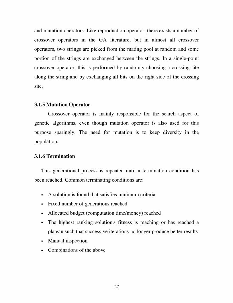
3.1.7 Simple generational genetic algorithm pseudo code
1. Choose initial population
2. Evaluate the fitness of each individual in the population
3. Repeat until termination: (time limit or sufficient fitness achieved)
1. Select best-ranking individuals to reproduce
2. Breed new generation through crossover and/or mutation
(genetic operations) and give birth to offspring
3. Evaluate the individual fitnesses of the offspring
4. Replace worst ranked part of population with offspring
The Flowchart below represents the Basic Genetic Algorithm
Fig. 2 Flowchart representing Basic Genetic Algorithm
29
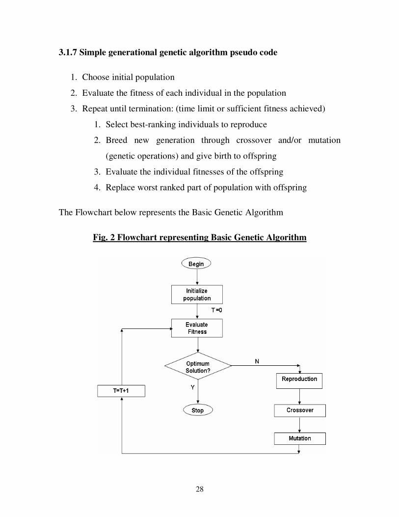
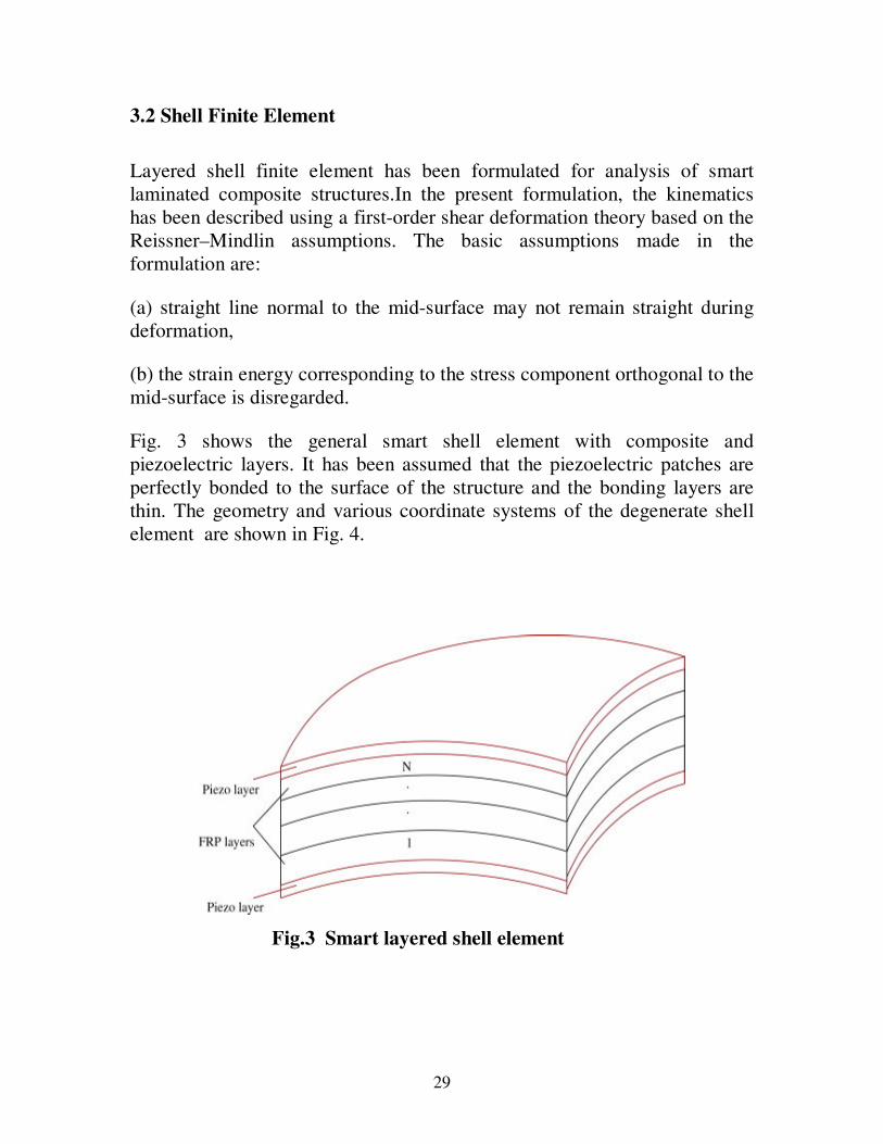
3.2 Shell Finite Element
Layered shell finite element has been formulated for analysis of smart
laminated composite structures.In the present formulation, the kinematics
has been described using a first-order shear deformation theory based on the
Reissner–Mindlin assumptions. The basic assumptions made in the
formulation are:
(a) straight line normal to the mid-surface may not remain straight during
deformation,
(b) the strain energy corresponding to the stress component orthogonal to the
mid-surface is disregarded.
Fig. 3 shows the general smart shell element with composite and
piezoelectric layers. It has been assumed that the piezoelectric patches are
perfectly bonded to the surface of the structure and the bonding layers are
thin. The geometry and various coordinate systems of the degenerate shell
element are shown in Fig. 4.
Fig.3 Smart layered shell element
30
Fig. 4 Shell element with various coordinates system
31
3.3 State Space Representation
In control engineering, state space representation is a mathematical
model of a physical system as a set of input, output and state variables
related by first-order differential equations. To abstract from the number of
inputs, outputs and states, the variables are expressed as vectors and the
differential and algebraic equations are written in matrix form (the last one
can be done when the dynamical system is linear and time invariant). The
state space representation (also known as the "time-domain approach")
provides a convenient and compact way to model and analyze systems with
multiple inputs and outputs.
The global sets of dynamic equations for piezo- elastic analysis can be
written as
[ ] [ ] uu uu uM d K d K Fφ φ + + = && (3.1)
uK d K Gφ φφ φ + = (3.2)
The coupled piezoelectric static equations can be as follows
[ ] uu uK d K Fφ φ + = (3.3)
uK d K Gφ φφ φ + = (3.4)
For open electrodes, charge can be expressed as
0G = (3.5)
Static displacement can be calculated from the Eq. (4.6)
[ ]
uu u th
u
K K d F
GK K
φ
φ φφφ
=
(3.6)
Dynamic responses of piezolaminated structures can be calculated due to
only dynamic loading from the Eq. (3.7)
32
[ ] [ ] ..
dy dy u a aM d K d F K φ φ + = − (3.7)
where [ ]M is the overall global mass matrix, [ ]K is the overall global elastic
stiffness matrix and [ ]uaK is the global piezoelectric coupling matrices of
actuator patches. The nodal dynamic displacement vector ( )dy
d t can be
approximated by the modal superposition of the first ‘r’ modes as
( ) [ ] ( )dy
d t tψ η≈ (3.8)
where [ ]1 2[ ] ......... rψ ψ ψ ψ= is the truncated modal matrix. The decoupled
dynamic equations of Eq. (3.7) considering modal damping can be written as
( ) ( ) [ ] [ ] [ ] .. .
22 ( )
T T
i di i i i i ua at t t F Kη ξ ω η ω η ψ ψ φ
+ + = −
(3.9)
wheredi
ξ is the damping ratio.
Eq. (3.9) can be represented in state-space form as
[ ] [ ]
.ˆ
a dX A X B B uφ = + + (3.10)
[ ][ ] [ ]
[ ]2
0
2i di i
IA
ω ξ ω
=
− − is the system matrix, [ ]
[ ]
[ ] [ ]
0
T
ua
BKψ
=
− is the control
matrix, [ ]
[ ]
0ˆ
TB
Fψ
=
is the disturbance matrix, d
u is the disturbance
input vector, aφ is the control input, and
.
.
..X
η
η
=
and .Xη
η
=
(3.11)
Two types of sensor output equations have been considered for mechanical
and thermo-mechanical loading. The sensor output equation [150] for
mechanical loading can be written as
33
0[ ]y C X= (3.12)
where output matrix 0[ ]C depends on the modal matrix [ ]ψ and the sensor
coupling matrix us
Kφ . And the sensor output equation for thermo-
mechanical loading has been proposed as
1
[0]s us
y K K dφφ φ
− = − (3.13)
3.3.1 Controllability index for actuator location
The system controllability is a basis in the modern control theory. Wang and
Wang [95] proposed a controllability index for actuator locations, which was
obtained by maximizing the global control force, and this has been
considered in the present study. The modal control force c
f applied to the
system can be written as
[ ] φ=c a
f B (3.14)
It follows from Eq. (3.14) that
[ ] [ ] φ φ=TT T
c c a af f B B (3.15)
Using the singular value analysis, [ ]B can be written as [ ] [ ][ ][ ]=T
B M S N
where [ ] [ ] [ ]=T
M M I , [ ] [ ] [ ]=T
N N I and [ ]
1 0
0
0 0
σ
σ
=
K
O M
M K
K
an
S
where a
n is the number of actuators. Equation (4.15) can be rewritten as
[ ][ ] [ ][ ] φ φ=T TT T
c c a af f N S S N or
2 2 2φ=
c af S
(3.16)
Thus, maximizing this norm independently on the input voltage φa
induces
maximizing2
S . The magnitude of σi is a function of location and the size of
34
piezoelectric actuators. Wang and Wang [1] proposed that the controllability
index is defined by
1
σ=
Ω = ∏an
ii
Maximize (3.17)
The higher the controllability index, the smaller will be the electrical
potential required for control. The control spillover effects are a significant
problem of active vibration control implementation on real structures.
Therefore, a similar controllability index has been proposed in the present
work incorporating residual modes of system/structures as follows
1 1
σ γ σ= =
′Ω = ∏ − ∏a an n
R
i ii i
Maximize (3.18)
where σ R
i are the components of [ ]RS corresponding to residual modes and
γ ′ is a weight
3.4 GA for Optimal Placement
Most natural representation in the form of a string of integers
specifying the locations of actuators has been used in this study. An integer
coded genetic (IGA) algorithm with uniform crossover and mutation have
been developed for optimal placement of actuators. In the present problem
the design variables are the positions of the actuators, and are represented in
a string of integers specifying the locations of actuators. The gene code is
taken as 1 2, ,......., ,......,aj n
ac ac ac ac , where (1, )∈j
ac m and is a positive integer
number and m is the total number of locations for actuators in the
structures/system. Uniform crossover and new mutation techniques for
integer coded genetic algorithm have been discussed in the following
subsections.
35
3.4.1 Uniform crossover
The steps involve in this crossover are
a) A random mask is generated
b) The mask determines which bits are copied from one parent and
which from the other parent
c) Bit density in mask determines how much material is taken from the
other parent
For example, if the randomly generated mask is 0110011000 and parents
are1010001110 and 0011010010 then their offspring will be 0011001010
and 1010010110.
3.4.2 Mutation
A one-digit positive integer value [1, ]j
ac m∈ is generated at random,
which replaces the old one when mutating. If j
ac is equal to old one, then a
new positive integer is selected again until they are different in the
chromosome. The efficiency of the mutation could be improved greatly
using the method.
3.4.3 Optimal Placement using IGA
The fitness value i.e. measure of controllability for the optimal
actuators location has been proposed as follows
36
1
1 1 11
-12
1 1
,
,
10 ,
a
a a a a
a a
n
ii
n n n nR R
i i i ii i ii
n nR
i ii i
without control spillover
ifconsidering control spillover
otherwise
σ
σ γ σ σ γ σ
σ γ σ
=
= = ==
= =
∏
Ω = ′ ′∏ − ∏ ∏ > ∏
′∏ − ∏ ×
(3.19)
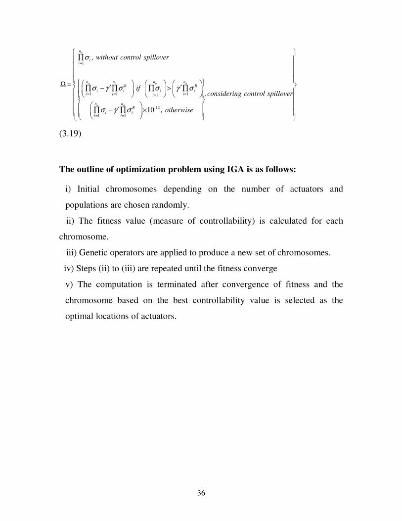
The outline of optimization problem using IGA is as follows:
i) Initial chromosomes depending on the number of actuators and
populations are chosen randomly.
ii) The fitness value (measure of controllability) is calculated for each
chromosome.
iii) Genetic operators are applied to produce a new set of chromosomes.
iv) Steps (ii) to (iii) are repeated until the fitness converge
v) The computation is terminated after convergence of fitness and the
chromosome based on the best controllability value is selected as the
optimal locations of actuators.
37
CHAPTER 4
RESULTS AND DISCUSSIONS
Based on the formulations discussed above, a computer code has been
developed for finite element analysis of smart shell structures followed by
optimal actuator placement.
4.1 Structural validation
In order to verify the finite element code developed, a spherical shell
made of graphite/epoxy with the four edges simply supported, having the
following dimensions have been considered: a/b=1, R1=R2=R, R/a=3,
a/h=10. Graphite/epoxy properties considered are as follows: E1=25E2,
G12=G13=0.5E2, υ12=0.25, G23=0.2E2. A 10×10 finite element mesh has been
used to model this entire shell.
4.2 Validation for optimal actuators placement
A smart fiber reinforced polymer (FRP) cantilever beam made of
GR/E has been considered to validate the code for optimal placement of
actuators as well as to compare the performances of integer and binary-
coded GA in terms of generation required to reach the optimal solution. In
this analysis, four actuators and first mode of vibration have been
considered. The length and width of the beam are taken as 0.2 and 0.01 m,
respectively. The stacking sequence of the laminated beam structure
considered is [p/[0/0]s/p]]. Here ‘p’ stands for piezo-patches one for sensing
and the other for actuation. Thickness of each ply has been considered as
0.15 mm and that of piezo-patch is 0.5 mm. The mechanical, electrical and
38
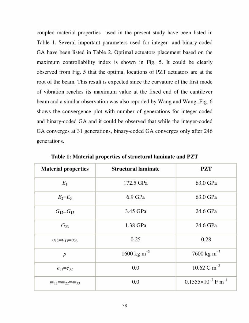
coupled material properties used in the present study have been listed in
Table 1. Several important parameters used for integer- and binary-coded
GA have been listed in Table 2. Optimal actuators placement based on the
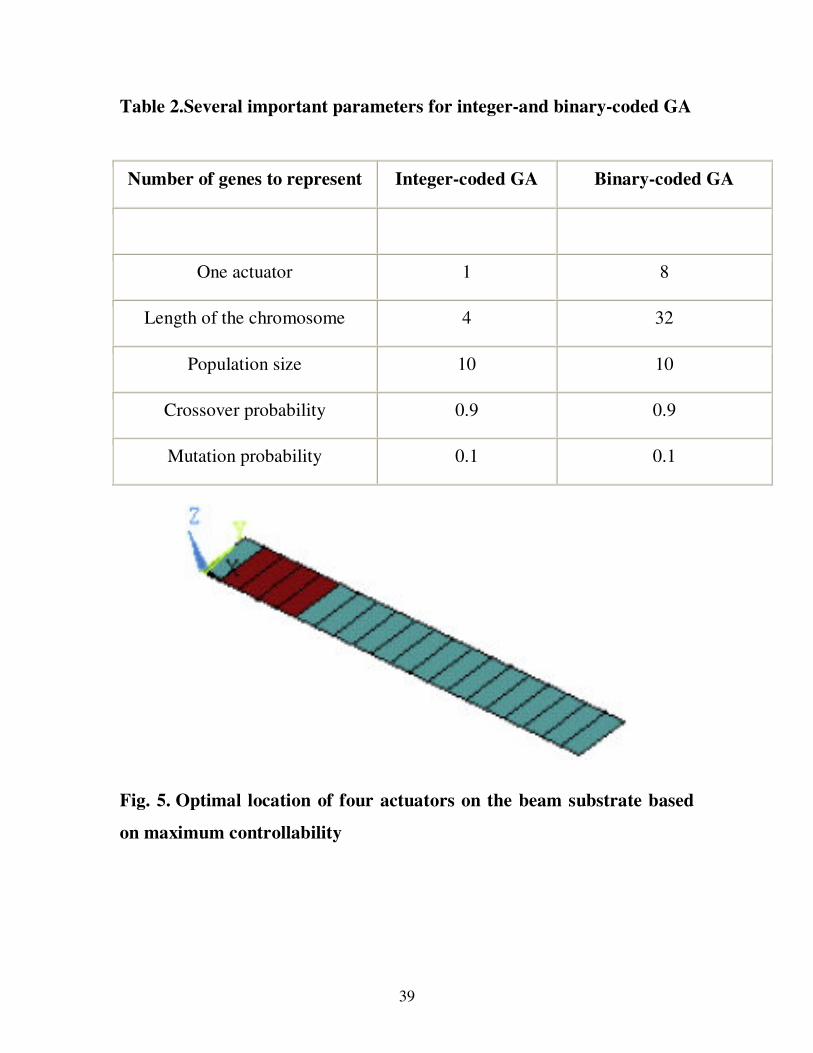
maximum controllability index is shown in Fig. 5. It could be clearly
observed from Fig. 5 that the optimal locations of PZT actuators are at the
root of the beam. This result is expected since the curvature of the first mode
of vibration reaches its maximum value at the fixed end of the cantilever
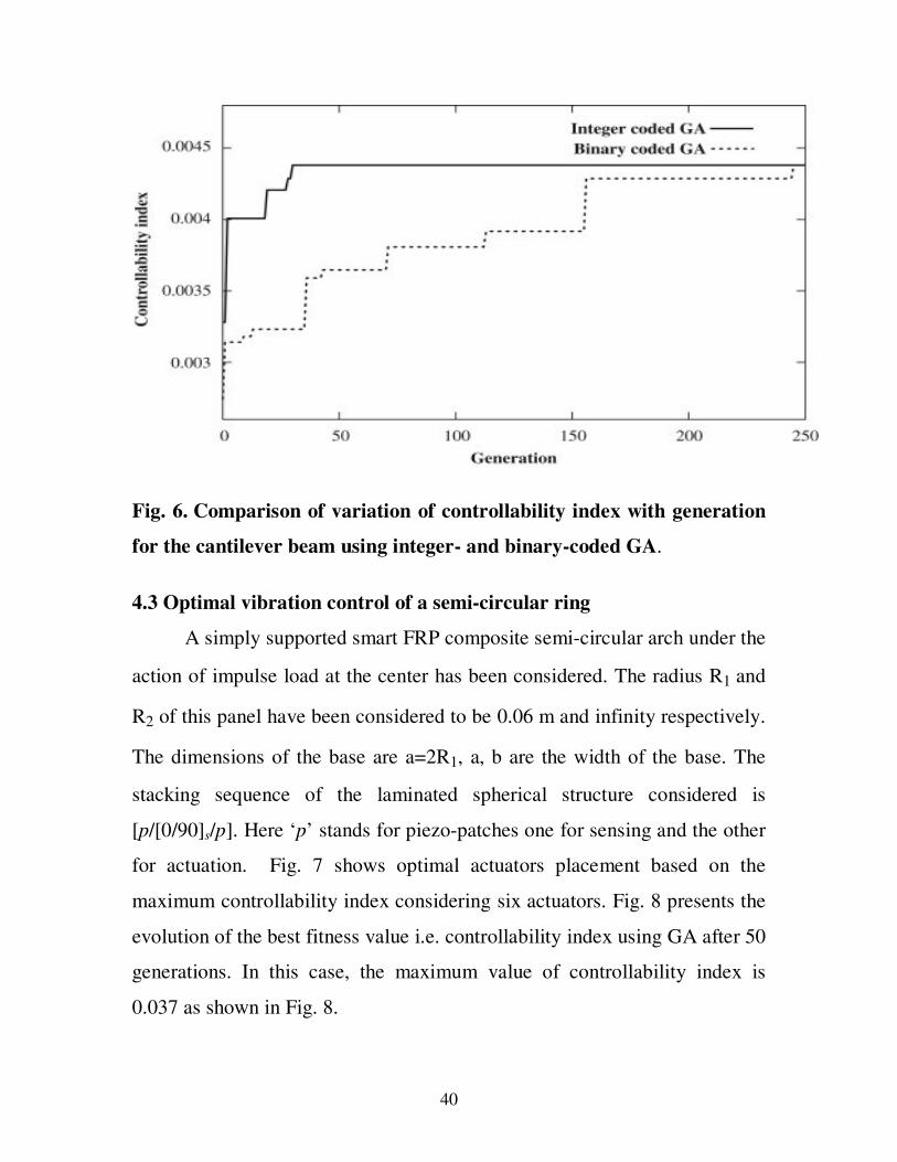
beam and a similar observation was also reported by Wang and Wang .Fig. 6
shows the convergence plot with number of generations for integer-coded
and binary-coded GA and it could be observed that while the integer-coded
GA converges at 31 generations, binary-coded GA converges only after 246
generations.
Table 1: Material properties of structural laminate and PZT
Material properties Structural laminate PZT
E1 172.5 GPa 63.0 GPa
E2=E3 6.9 GPa 63.0 GPa
G12=G13 3.45 GPa 24.6 GPa
G23 1.38 GPa 24.6 GPa
υ12=υ13=υ23 0.25 0.28
ρ 1600 kg m−3
7600 kg m−3
e31=e32 0.0 10.62 C m−2
11= 22= 33 0.0 0.1555×10⁻⁷
F m−1
39
Table 2.Several important parameters for integer-and binary-coded GA
Number of genes to represent Integer-coded GA Binary-coded GA
One actuator 1 8
Length of the chromosome 4 32
Population size 10 10
Crossover probability 0.9 0.9
Mutation probability 0.1 0.1
Fig. 5. Optimal location of four actuators on the beam substrate based
on maximum controllability
40
Fig. 6. Comparison of variation of controllability index with generation
for the cantilever beam using integer- and binary-coded GA.
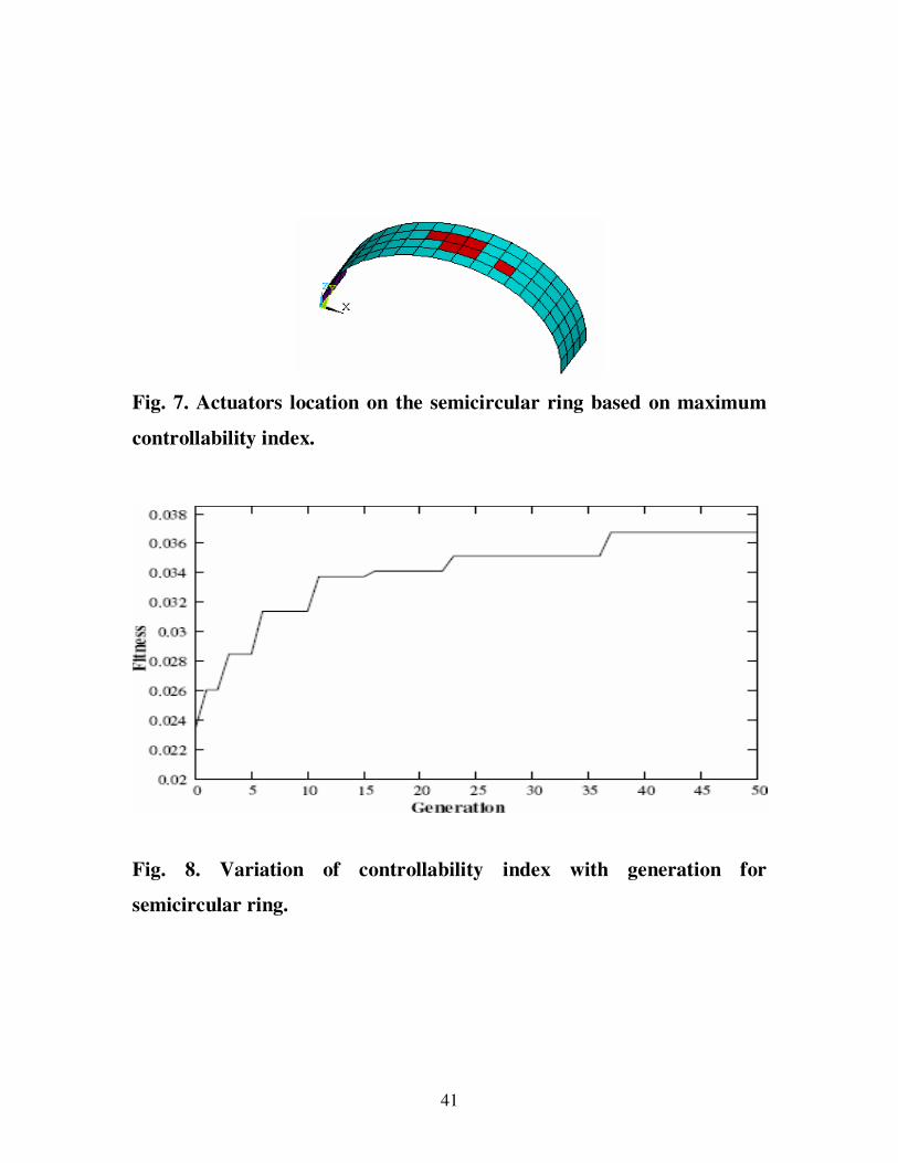
4.3 Optimal vibration control of a semi-circular ring
A simply supported smart FRP composite semi-circular arch under the
action of impulse load at the center has been considered. The radius R1 and
R2 of this panel have been considered to be 0.06 m and infinity respectively.
The dimensions of the base are a=2R1, a, b are the width of the base. The
stacking sequence of the laminated spherical structure considered is
[p/[0/90]s/p]. Here ‘p’ stands for piezo-patches one for sensing and the other
for actuation. Fig. 7 shows optimal actuators placement based on the
maximum controllability index considering six actuators. Fig. 8 presents the
evolution of the best fitness value i.e. controllability index using GA after 50
generations. In this case, the maximum value of controllability index is
0.037 as shown in Fig. 8.
41
Fig. 7. Actuators location on the semicircular ring based on maximum
controllability index.
Fig. 8. Variation of controllability index with generation for
semicircular ring.
42
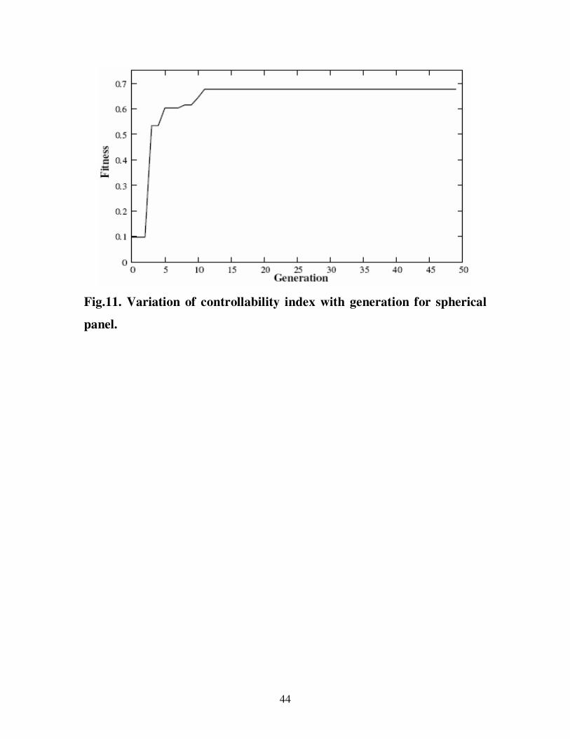
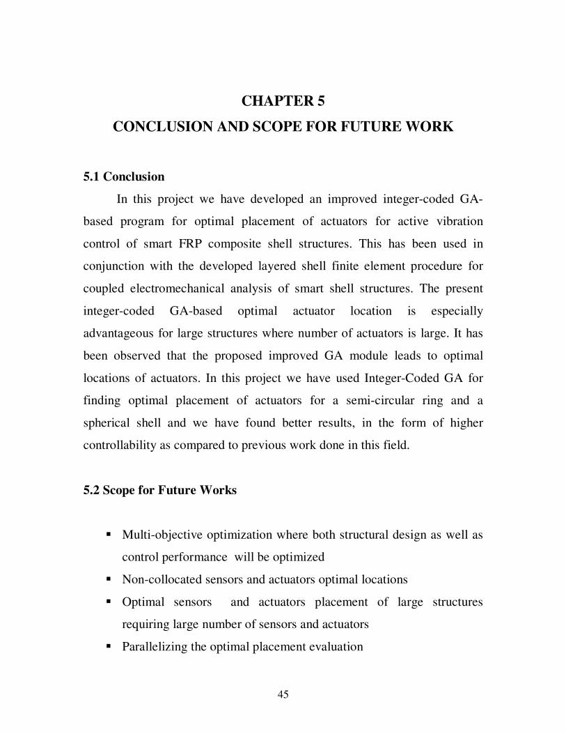
4.4 Optimal vibration control of laminated spherical shell panel
A simply supported smart FRP composite shell panel on a square base
(a=b=0.02 m) under the action of impulse load at the center has been
considered. The radius (i.e. R1=R2=R) of this panel has been considered to be
0.06 m. The stacking sequence of the laminated spherical structure
considered is [p/[0/90]s/p]. Here ‘p’ stands for piezo-patches one for sensing
and the other for actuation. Thickness of each ply has been considered to be
0.25 mm and that of piezo-patch has been taken as 0.5 mm. A 10×10 finite
element mesh has been considered to model this entire panel. Two types of
piezo-patch locations viz. Placement1 has been considered to study
influence of optimal placement on the input voltage of actuator and the
closed-loop damping ratio. Placement1 stands for optimal actuators
placement based on the maximum controllability index considering six
actuators as shown in Fig. 10. Fig. 11 presents the evolution of the best
fitness value i.e. controllability index using GA after 50 generations. In case
of Placement1, the maximum value of controllability index is 0.680956 as
shown in Fig. 11.
43
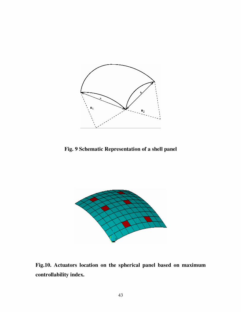
Fig. 9 Schematic Representation of a shell panel
Fig.10. Actuators location on the spherical panel based on maximum
controllability index.
44
Fig.11. Variation of controllability index with generation for spherical
panel.
45
CHAPTER 5
CONCLUSION AND SCOPE FOR FUTURE WORK
5.1 Conclusion
In this project we have developed an improved integer-coded GA-
based program for optimal placement of actuators for active vibration
control of smart FRP composite shell structures. This has been used in
conjunction with the developed layered shell finite element procedure for
coupled electromechanical analysis of smart shell structures. The present
integer-coded GA-based optimal actuator location is especially
advantageous for large structures where number of actuators is large. It has
been observed that the proposed improved GA module leads to optimal
locations of actuators. In this project we have used Integer-Coded GA for
finding optimal placement of actuators for a semi-circular ring and a
spherical shell and we have found better results, in the form of higher
controllability as compared to previous work done in this field.
5.2 Scope for Future Works
Multi-objective optimization where both structural design as well as
control performance will be optimized
Non-collocated sensors and actuators optimal locations
Optimal sensors and actuators placement of large structures
requiring large number of sensors and actuators
Parallelizing the optimal placement evaluation
46
CHAPTER 6
REFERENCES:
1. S. L. Padula, R. K. Kincaid, Optimization strategies for sensor and
actuator placement, Technical Report NASA/TM-1999-209126.
2. M. I. Frecker, Recent advances in optimization of smart structures and
actuators, J. Intell. Mater. Syst. Struct. 14 (2003) 207–216.
3. J. J. Hollkamp, Multimodal passive vibration suppression with
piezoelectric materials and resonant shunts, J. Intell. Mater. Syst.
Struct. 5 (1994) 49–57.
4. Y. K. Kang, H. C. Park, W. Hwang , K. S. Han, Optimum placement
of piezoelectric sensor/actuator for vibration control of laminated
beams, AIAA Journal 34 (1996) 1921–1926
5. N. Zhang, I. Kirpitchenko, Modelling dynamics of a continuous
structure with a piezoelectric sensor/actuator for passive structural
control, Journal of Sound and Vibration 249 (2) (2002) 251-261.
6. J. A Main, E. Garcia, D. Howard, Optimal placement and sizing of
paired piezoactuators in beam plate, Smart Mater. Struct. 3 (1994)
373-381.
7. Y. Li, J. Onoda, K Minesugi, Simultaneous optimization of
piezoelectric actuator placement and feedback for vibration
suppression, Acta Astronaut. 50 (2002) 335–341.
8. Y. K. Kang, H. C. Park, B. Agrawal, Optimization of piezoceramic
sensor/actuator placement for vibration control of laminated plates,
AIAA Journal 36 (1998)1763–1765.
47
9. K. Hiramoto, H. Doki, G. Obinata, Optimal sensor/actuator placement
for active vibration control using explicit solution of algebraic Riccati
equation, Journal of Sound and Vibration 229 (5) (2000) 1057-1075.
10. A. Mukherjee, S. P. Joshi, Design of Actuator Profiles for Minimum
Power Consumption, Smart Materials and Structures 10(2) (2001)
305–313.
11. Q. Wang, C. Wang, A controllability index for optimal design of
piezoelectric actuators in vibration control of beam structures, Journal
of Sound and Vibration 242 (3) (2001) 507-518
12. F. Seeger, U. Gabbert, Optimal placement of distributed actuators for
a controlled smart elastic plate, Proc. Appl. Math. Mech. 2 (2003)
262–263.
13. D. Sun, L. Tong, D. Wang, Vibration control of plates using discretely
distributed piezoelectric quasi-modal actuators/sensors, AIAA Journal
39 (2001) 1766–1772.
14. D. Sun, L. Tong, Modal control of smart shells by optimized
discretely distributed piezoelectric transducers, Int. J. Solids Struct. 38
(2001) 3281–3299.
15. S. Leleu, H. Abou-Kandil, Y. Bonnassieux, Piezoelectric Actuators
and Sensors Location for Active Control of Flexible Structures, IEEE
Transactions On Instrumentation And Measurement 50 (6) (2001)
1577-1582.
16. M. R. Kermani, M. Moallem, R. V. Patel, Optimizing the
Performance of Piezoelectric Actuators for Active Vibration Control,
Proceedings of the 2002 IEEE, International Conference on Robotics
& Automation, Washington, DC , May 2002.
48
17. M. Rose, Modal based correction methods for the placement of
piezoceramic modules, ASME Int. Mechanical Engineering Congr.
and Exposition, Orlando, FL, Nov. 2005.
18. D. Halim, S. O. R. Moheimani, An optimization approach to optimal
placement of collocated piezoelectric actuators and sensors on a thin
plate, Mechatronics 13 (2003) 27–47.
19. D. Sun, L. Tong, Design optimization of piezoelectricactuator patterns
for static shape control of smart plates, Smart Mater. Struct. 14 (2005)
1353–1362.
20. R. C. Carbonari, E. C. N. Silva, S. Nishiwaki, Optimum placement of
piezoelectric material in piezoactuator design, Smart Mater. Struct. 16
(2007) 207–220.
21. S. S. Rao, T-S Pan, V. B. Venkayya, Optimal placement of actuators
in actively controlled structures using genetic algorithms, AIAA
Journal 29 (1991) 942–943.
22. Y. J. Yan, L. H. Yam, Optimal design of number and locations of
actuators in active vibration control of a space truss, Smart Mater.
Struct. 11 (2002) 496–503.
23. J. A. Bishop, A. G. Striz, On using genetic algorithms for optimum
damper placement in space trusses, Struct. Multidisciplinary Optim.
28 (2004)136–145.
24. M. M.Abdullah, A. Richardson, J. Hanif, Placement of
sensors/actuators on civil structures using genetic algorithms,
Earthquake Engineering & Structural Dynamics 30 (8) (2001) 1167-
1184.
25. A. Richardson, M. M. Abdullah, Sensor/actuators placement on civil
structures using a real coded genetic algorithm, SPIE Smart Structures
49
and Materials—Smart Systems for Bridges, Structures, and Highways
, San Diego, CA, pp. 244–255 2002.
26. P. Gaudenzi, E. Fantini, V. K. Koumousis, C J Gantes, Genetic
algorithm optimization for the active control of a beam by means of
PZT actuators J. Intell. Mater. Syst. Struct. 9 (1998) 291–300.
27. H. Zhang, B. Lennox, P. R. Goulding, A. Y. T. Leung , A float-
encoded genetic algorithm technique for integrated optimization of
piezoelectric actuator and sensor placement and feedback gains, Smart
Mater. Struct. 9 (2000) 552–557.
28. Y. Yang, Z. Jin, C. K. Soh, Integrated optimal design of vibration
control system for smart beams using genetic algorithms, Journal
Sound and Vibration 282 (2005) 1293–1307.
29. Y. Yang, Z. Jin, C. K. Soh, Integrated optimization of control system
for smart cylindrical shells using modified GA, J. Aerosp. Eng. 19
(2006) 68–79.
30. J-H Han, I. Lee, Optimal placement of piezoelectric sensors and
actuators for vibration control of a composite plate using genetic
algorithms, Smart Mater. Struct. 8 (1999) 257–267.
31. A. M. Sadri, J. R. Wright, R. J. Wynne, Modelling and optimal
placement of piezoelectric actuators in isotropic plates using genetic
algorithms Smart Mater. Struct. 8 (1999) 490–498
32. A. M. Sadri, J. R. Wright, R. J. Wynne, LQG control design for panel
flutter suppression using piezoelectric actuators, Smart Mater. Struct.
11 (2002) 834–839.
33. S. T. Quek, S. Y. Wang, K. K. Ang, Vibration control of composite
plates via optimal placement of piezoelectric patches, J. Intell. Mater.
Syst. Struct. 14 (2003) 229–245.
50
34. H. Y. Guo, L. Zhang, L. L. Zhang, J. X Zhou, Optimal placement of
sensors for structural health monitoring using improved genetic
algorithm, Journal of Smart Materials and Structures 13 (2004) 528-
534.
35. Q. S. Li, D. K Liu, J. Tang, N. Zhang, C. M. Tam, Combinatorial
optimal design of number and positions of actuators in actively
controlled structures using genetic algorithm, Journal of Sound and
Vibration 270 (2004) 611-624.
36. F. Peng, A. Ng, Y-R Hu, Actuator placement optimization and
adaptive vibration control of plate smart structures, J. Intell. Mater.
Syst. Struct. 16 (2005) 263–271.
37. S. Y. Wang, K. Tai, S. T. Quek, Topology optimization of
piezoelectric sensors/actuators for torsional vibration control of
composite plates, Smart Mater. Struct. 15 (2006) 253–269.
38. W. Liu, Z. K.Hou, M. A. Demetriou, A computational scheme for the
optimal sensor/actuator placement of flexible structures using spatial
H-2 measures, Mechanical Systems and Signal Processing 20 (4)
(2006) 881-895.
39. A. K. Jha, D. J. Inman, Optimal sizes and placements of piezoelectric
actuators and sensors for an inflated torus, J. Intell. Mater. Syst.
Struct. 14 (2003) 563–576.
40. A. Belloli, P. Ermanni, Optimum placement of piezoelectric ceramic
modules for vibration suppression of highly constrained structures,
Smart Mater. Struct. 16 (2007) 1662-1671.
41. Holland, J. H. (1975). Adaptation in Natural and Artificial Systems.
The University of Michigan Press, Ann Arbor, MI.
51
42. Jong, K. A. D. (1975). An Analysis of the Behavior of a Class of
Genetic Adaptive Systems. PhD thesis, University of Michigan, Ann
Arbor, MI. Deptartment of Computer and Communication Sciences.
43. Goldberg, D. E. (1989). Genetic Algorithms in Search, Optimization,
and Machine Learning. Addison-Wesley, Reading, MA