Embed Size (px)
Citation preview
1
Optimal Construction of Regenerating Code throughRate-matching in Hostile Networks
Jian Li, and Tongtong Li Senior Member, IEEE and Jian Ren Senor Member, IEEE
Abstract—Regenerating code is a class of distributed storagecodes that can optimally trade the bandwidth required to repaira failed node with the amount of data stored per node. Thereare two optimal points in the regeneration tradeoff curve: theminimum storage regeneration (MSR) code and the minimumbandwidth regeneration (MBR) code. However, in hostile net-works where the storage nodes may be compromised, the storagecapacity of the network can be significantly affected. In thispaper, we propose two optimal regenerating code constructionsthrough rate-matching to combat this kind of adversarial attacksin hostile networks. We first develop a 2-layer rate-matchedregenerating code construction. By matching the parameters ofthe full rate code and the partial rate code, we can optimizethe overall storage efficiency while maintaining the corruptednode detection probability. Through comprehensive analysis,we shows that the 2-layer rate-matched regenerating code canachieve 70% higher storage efficiency compared to the universallyresilient regenerating code. We then propose an optimal m-layerregenerating code construction. While the principle remains thesame as the 2-layer code, it is designed to optimize the totalnumber of detectable corrupted nodes of m layers from whichthe errors can be corrected under the constraint of any givencode efficiency. Compared to the universally resilient regeneratingcode with the same rate, our m-layer code can detect 50% morecorrupted nodes.
Index Terms—Optimal regenerating code, MDS code, error-correction, adversary attack.
I. INTRODUCTION
Distributed storage is a popular method to provide reli-able data storage. Instead of storing a file and its replicasin multiple servers, we can break the file into componentsand store the components into multiple servers. In this way,while increasing data reliability, we can also achieve dataconfidentiality without data encryption and key managementinvolved. A typical approach is to encode the file using an(n, k) Reed-Solomon (RS) code and distribute the encodedfile into n servers. When we need to recover the file, weonly need to collect the encoded parts from any k servers,which achieves a trade-off between reliability and efficiency.However, when repairing or regenerating the contents of afailed node, the whole file has to be recovered first, which isa waste of bandwidth.
The concept of regenerating code was introduced in [1],where a replacement node is allowed to connect to someindividual nodes directly to regenerate a substitute of the failed
This paper was presented in part at the Resilience Week (RWS), 2015.This work was supported in part by the National Science Foundation under
CNS-1217206, CNS-1232109 and CNS-1524520.The authors are with the Department of ECE, Michigan State University,
East Lansing, MI 48824-1226. Email: {lijian6, tongli, renjian}@msu.edu
node, instead of first recovering the original data then regener-ating the failed component. Compared to the RS code, regen-erating code achieves the optimal trade-off between bandwidthand storage within the minimum storage regeneration (MSR)and the minimum bandwidth regeneration (MBR) points.
However, when malicious behaviors exist in the network,both the regeneration of the failed node or the reconstructionof the original file could fail. The error resilience of the Reed-Solomon code based regenerating code in the network witherrors and erasures was analyzed in [2]. In our previous work,a Hermitian code based regenerating code [3] was proposedto provide better error correction capability compared to theReed-Solomon code based approach.
Inspired by the great performance improvement of theHermitian code based regenerating codes, in this paper wemove a step forward to construct optimal regenerating codesin distributed storage with structure similar to the Hermitiancode.
The main contributions of this paper are:
• We propose an optimal construction of 2-layer rate-matched regenerating code. Both theoretical analysis andperformance evaluation show that this code can achievestorage efficiency much higher than that of the universallyresilient regenerating code proposed in [2].
• We propose an optimal construction of m-layer rate-matched regenerating code. The m-layer code can achieveoptimal error correction capability, which is much higherthan that of the code proposed in [2] and the Her-mitian code based regenerating code proposed in [3].Furthermore, the m-layered code is easier to understandand has more flexibility than the Hermitian code basedregenerating code.
Here we will focus on malicious/compromised node locatingfrom which the error can be corrected in distributed dataregeneration and reconstruction. When no error occurs or nomalicious node exists, the data regeneration and reconstructionshould be processed the same as the existing works.
It is worth noting that although there are two types ofregenerating codes: MSR and MBR codes on the MSR andMBR points, respectively, in this paper we will only focuson the optimization of the MSR code for the following tworeasons:
1) The processes and results of the optimization for thesetwo codes are similar. The optimization for the MSRcode can be directly applied to the MBR code withsimilar optimization results.
2
2) The differences between the constructions of MSR andMBR codes have little impact on the optimization pro-posed in this paper.
The rest of this paper is organized as follows: in Section II,we introduce the related work. In Section III, the preliminaryof this paper is presented. In Section IV, we propose twocomponent codes for the rate-matched regenerating codes.We present and analyze the 2-layer rate-matched regeneratingcode in Section V. Then we propose and study the m-layerrate-matched regenerating code in Section VI. The paper isconcluded in Section VII.
II. RELATED WORK
When a storage node in the distributed storage networkthat employs the conventional (n, k) RS code (such asOceanStore [4] and Total Recall [5]) fails, the replacementnode connects to k nodes and recovers the whole file toregenerate the symbols stored in the failed node. This approachis a waste of bandwidth because the whole file has to bedownloaded to recover a fraction of it. To overcome thisdrawback, Dimakis et al. [1] introduced the conception of{n, k, d, α, β,B} regenerating code based on the networkcoding. In the context of regenerating code, the replace-ment node can regenerate the contents stored in a failednode by downloading γ help symbols from d helper nodes.The bandwidth consumption for the failed node regenerationcould be far less than the whole file. A data collector (DC)can reconstruct the original file stored in the network bydownloading α symbols from each of the k storage nodes.In [1], the authors proved that there is a trade-off betweenbandwidth γ and per node storage α. They found two optimalpoints: minimum storage regeneration (MSR) and minimumbandwidth regeneration (MBR) points. The existing work haslargely focused on the optimal regenerating codes design [6]–[18], and implementation of the regenerating code [19], [20].
The regenerating code can be divided into functional regen-eration and exact regeneration. In the functional regeneration,the replacement node regenerates a new component that canfunctionally replace the failed component instead of being thesame as the originally stored component. In [21], the dataregeneration was formulated as a multicast network codingproblem. The paper also constructed functional regeneratingcodes. A random linear regenerating codes for distributedstorage systems was implemented in [22]. It has been provedthat by allowing data exchange among the replacement nodes,a better trade-off between repair bandwidth γ and per nodestorage α can be achieved [23]. In [24], the authors proposeda functional regenerating code with less computational com-plexity through binary operations. In the exact regeneration,the replacement node regenerates the exact symbols of a failednode. In [25], the authors proposed to reduce the regenerationbandwidth through algebraic alignment. A code structure forexact regeneration using interference alignment technique wasprovided in [26]. In [27], an optimal exact constructions ofMBR codes and MSR codes under product-matrix frameworkwas presented. This is the first work that allows independentselection of the node number n in the network. In [28], repair
performance of the Reed-Solomon codes was studied. A codeconstruction that could achieve performance better than space-sharing between the minimum storage regenerating codes andthe minimum bandwidth regenerating codes was proposedin [29].
However, none of these works considered code regenerationunder node corruption or adversarial manipulation attacks inhostile networks. In fact, all these schemes will fail in bothregeneration and reconstruction if some nodes in the storagecloud send out incorrect responses to the regeneration andreconstruction requests.
In [30], the Byzantine fault tolerance of regenerating codeswas studied. The amount of information that can be safelystored against passive eavesdropping and active adversarialattacks based on the regeneration structure was discussedin [31]. To check data integrity of the regenerating code inhostile networks, CRC code was adopted in [32]. Unfortu-nately, the CRC checks can be easily manipulated by themalicious nodes, resulting in the failure of the regenerationand reconstruction. In [33], data integrity protection (DIP)was designed under a mobile Byzantine adversarial modelto enable a client to verify the integrity of the outsourceddata against general or malicious corruptions in distributedstorage. In [34], the authors proposed to use erasure-codingand threshold cryptography to achieve storage efficiency andresilience. In [35], the verification cost for both the clientread and write operations in workloads with idle periods wasanalyzed.
In [2], error resilience of the RS code based regeneratingcode in the network with both errors and erasures was evalu-ated. They provided the theoretical error correction capability.In [3], a Hermitian code based regenerating code was pro-posed. This code can provide better error correction capabilityunder the same code efficiency. In [36], the universally secureregenerating code was developed to achieve information theo-retic data confidentiality. However, the paper did not considerthe extra computational cost and bandwidth for this code.In [37], the authors proposed to apply linear feedback shiftregister (LFSR) to protect the data confidentiality. In [38], theauthors discussed the optimal trade-off between the storagespace and the repair bandwidth in presence of two types ofwiretapper.
III. PRELIMINARY AND ASSUMPTIONS
A. Regenerating CodeRegenerating code introduced in [1] is a linear code over
finite field Fq with a set of parameters {n, k, d, α, β,B}. A fileof size B is stored in n storage nodes, each of which storesα symbols. A replacement node can regenerate the contentsof a failed node by downloading β symbols from each ofd randomly selected storage nodes. So the total bandwidthneeded to regenerate a failed node is γ = dβ. The datacollector (DC) can reconstruct the whole file by downloadingα symbols from each of k ≤ d randomly selected storagenodes. In [1], the following theoretical bound was derived:
B ≤k−1∑i=0
min{α, (d− i)β}. (1)
3
From equation (1), a trade-off between the regeneration band-width γ and the storage requirement α was derived. Theycannot be decreased at the same time. There are two specialcases: minimum storage regeneration (MSR) point in whichthe storage parameter α is minimized:
(αMSR, γMSR) =
(B
k,
Bd
k(d− k + 1)
), (2)
and minimum bandwidth regeneration (MBR) point in whichthe bandwidth γ is minimized:
(αMBR, γMBR) =
(2Bd
2kd− k2 + k,
2Bd
2kd− k2 + k
). (3)
B. System Assumptions and Adversarial Model
In this paper, we assume there is a secure server that isresponsible for encoding and distributing the data to storagenodes. The secure server will initialize the replacement nodes.The DC and the secure server can be implemented in the samecomputer. We assume this server will never be compromised.We use the notation F/P to refer to either the full/partial rateMSR code or a codeword of the full/partial rate MSR code.The exact meaning can be clearly understood according to thecontext.
Our adversary model is the same as [2]. We assume somenetwork nodes may be corrupted due to hardware failure orcommunication errors, and/or compromised by malicious userswhich can take full control of up to τ ≤ n storage nodes andcollude to perform attacks. Since our proposed codes workfor all these cases, in the paper we will refer these nodesas corrupted nodes without distinguishing the specific errorsources. As a result, upon request, these nodes may sendout incorrect responses to disrupt the data regeneration andreconstruction.
We will refer the maximum number of corrupted nodesfrom which the errors can be corrected as the error correctioncapability.
IV. COMPONENT CODES OF RATE-MATCHEDREGENERATING CODE
In this section, we will introduce two different componentcodes for rate-matched MSR code on the MSR point withd = 2k−2. The code based on the MSR point with d > 2k−2can be derived in the same way through truncating operations.In the rate-matched MSR code, there are two types of MSRcodes with different code rates: full rate code and partial ratecode.
A. Full Rate Code
1) Encoding: The full rate code {n, k, d, α, β,BF} is en-coded based on the product-matrix code framework proposedin [27]. According to equation (2), we have α = d/2, β = 1for one block of data with the size BF = kα = (α+ 1)α. Thed× α message matrix MF is defined as
MF =
[S1
S2
],
where S1 and S2 are α×α symmetric matrices, each of whichwill contain BF/2 data. We further define the n× d encodingmatrix Ψ as Ψ = [Φ ΛΦ], where
Φ =
1 1 1 . . . 11 g g2 . . . gα−1
......
.... . .
...1 gn−1 (gn−1)2 . . . (gn−1)α−1
(4)
is an n×α Vandermonde matrix and Λ = diag[λ1, λ2, · · · , λn]is an n × n diagonal matrix such that λi ∈ Fq and λi 6= λjfor 1 ≤ i, j ≤ n, i 6= j, g is a primitive element in Fq , andany d rows of Ψ are linearly independent.
The codeword F is defined as
F = [Φ ΛΦ]
[S1
S2
]= ΨMF =
f1...fn
. (5)
Each row fi = ψiMF (1 ≤ i ≤ n) of the codeword matrixF will be stored in storage node i, where the encoding vectorψi is the ith row of Ψ.
2) Regeneration: Suppose node z fails, the replacementnode z′ will send regeneration requests to the rest of then− 1 helper nodes. Upon receiving the regeneration request,helper node i will calculate and send out the help symbolhi = fiφ
Tz = ψiMFφ
Tz , where φz is the zth row of Φ
and φTz is the transpose of φz . For i ≤ j, we defineΨi→j =
[ψTi ,ψ
Ti+1 · · · ,ψ
Tj
]T, and x(j) to be the vector
containing the first j symbols of MFφTz for convenience.
Suppose h′i = hi+ ei is the response from helper node i. Ifei ∈ Fq\{0}, then node i is corrupted since the response hihas been modified. We can successfully regenerate the symbolsin node z when the total number of received help symbolsh′i being modified from the n − 1 helper nodes is less thanb(n− d− 1)/2c, where bxc is the floor operation of x, whichrepresents the greatest integer less than or equal to x. Withoutloss of generality, we assume 1 ≤ i ≤ n− 1. z′ will performAlgorithm 1 to regenerate the contents of the failed node z.
Algorithm 1. z′ regenerates symbols of the failed node z.Step 1: Decode h′ to hcw, where h′ = [h′1, h
′2, · · · , h′n−1]T
can be viewed as an MDS code with parameters (n−1, d, n− d) since Ψ1→(n−1) · x(n−1) = h′.
Step 2: Solve Ψ1→(n−1) · x(n−1) = hcw and compute fz =φzS1 + λzφzS2 as described in [27].
Proposition 1. For regeneration, the full rate code can correcterrors from b(n− d− 1)/2c corrupted nodes, where bxc is thefloor operation.
3) Reconstruction: When the DC needs to reconstruct theoriginal file, it will send reconstruction requests to n storagenodes. Upon receiving the request, node i will send out thesymbol vector ci to the DC. Suppose c′i = ci + ei is theresponse from storage node i. If ei ∈ Fαq \{0}, then node iis corrupted since the response ci has been modified.
The DC will reconstruct the file as follows: Let R′ =[f ′1T, f ′2
T, · · · , f ′n
T]T , we have
R′ = Ψ
[S′1S′2
]= [Φ ΛΦ]
[S′1S′2
],
4
R′ΦT = ΦS′1ΦT + ΛΦS′2ΦT . (6)
Let C = ΦS′1ΦT , D = ΦS′2ΦT , and R′ = R′ΦT , then
C + ΛD = R′. (7)
Since C,D are both symmetric, we can solve the non-diagonalelements of C,D as follows:{
Ci,j + λi ·Di,j = R′i,jCi,j + λj ·Di,j = R′j,i.
(8)
Because matrices C and D have the same structure, here weonly focus on C (corresponding to S′1). It is straightforward tosee that if node i is corrupted and there are errors in the ith rowof R′, there will be errors in the ith row of R′. Furthermore,there will be errors in the ith row and ith column of C.
Define S′1ΦT = S′1, we have ΦS′1 = C. We can view eachcolumn of C as an (n− 1, α, n−α) MDS code because Φ isa Vandermonde matrix. The length of the code is n− 1 sincethe diagonal elements of C is unknown. Suppose node j is alegitimate node, we can decode the MDS code to recover thejth column of C and locate the corrupted nodes. EventuallyC can be recovered. So the DC can reconstruct S1 using themethod similar to [3], [27]. For S2, the recovering process issimilar.
Proposition 2. For reconstruction, the full rate code cancorrect errors from b(n− α− 1)/2c corrupted nodes.
B. Partial Rate Code
1) Encoding: For the partial rate code, we also have α =d/2, β = 1 for one block of data with the size
BP=
{12xd(1+xd), x∈(0,0.5]
12 (α(α+1)+(x−0.5)d(1+(x−0.5)d),x∈(0.5,1]
, (9)
where x is the match factor of the rate-matched MSR code.It is easy to see that the partial rate code will become the fullrate code when x = 1.
The data m = [m1,m2, . . . ,mBP] ∈ FBP
q will be processedas follows:• When x ≤ 0.5, the data will be arranged into a matrixS1 of the size α× xd, where the first xd rows form asymmetric submatrix:
S1 =
m1 m2 . . . mxd
m2 mxd+1 . . . m2xd−1...
.... . .
...mxd m2xd−1 . . . mBP
0 0 . . . 0...
.... . .
...0 0 . . . 0
. (10)
The codeword P is defined as
P =
[Φ ΛΦ]
[S1
0
] r1,1 r1,2 . . . r1,α−xd...
.... . .
...rn,1 rn,2 . . . rn,α−xd
= [ ΨMP ‖ R ] ,(11)
where 0 is the α× xd zero matrix, Φ,Λ,Ψ are the sameas the full rate code, ri,1, ri,2, . . . , ri,α−xd (1 ≤ i ≤ n)are random numbers generated by the secure server, Ris the corresponding random number matrix, and ‖ isthe concatenation operator. Through the insertion of therandom numbers, codeword of partial rate code withx < 0.5 will have the same appearance as the codewordof full rate code. This can prevent the attackers fromdiscriminating between the partial rate code and full ratecode. And the random numbers can be easily reproducedby the secure server for regeneration and reconstruction,making the additional overhead negligible. It is alsointeresting to point out that xd will be an integer in theoptimal selection according to equation (20) and equation(21).
• When x > 0.5, the first α(α+ 1)/2 data will be arrangedinto an α× α symmetric matrix S1. The rest of the datamα(α+1)/2+1, . . . ,mBP
will be arranged into another α×α symmetric matrix S2:
S2=
mα(α+1)/2+1 ... mα(α+1)/2+(x−0.5)d 0 ... 0mα(α+1)/2+2 ... mα(α+1)/2+2(x−0.5)d−1 0 ... 0
.... . .
......
. . ....
mα(α+1)/2+(x−0.5)d ... mBP 0 ... 00 ... 0 0 ... 0...
. . ....
.... . .
...0 ... 0 0 ... 0
.
(12)The codeword P is defined the same as equation (5) withthe same parameters Φ,Λ and Ψ. Then each row pi (1 ≤i ≤ n) of the codeword matrix P will be stored in storagenode i respectively, in which the encoding vector ψi isthe ith row of Ψ.
Proposition 3. The partial rate code can achieve the MSRpoint in equation (2) since it is encoded under the product-matrix MSR code framework in [27].
2) Regeneration: The regeneration for the partial rate codeis the same as the regeneration for the full rate code describedin Section IV-A2 with only a minor difference. If we definex(j) as the vector containing the first j symbols of MPφ
Tz ,
there will be only xd nonzero elements in the vector. Accord-ing to Ψ1→n−1 · x(n−1) = h′, the received symbol vector h′
for the partial rate code in Step 1 of Algorithm 1 can be viewedas an (n− 1, xd, n− xd) MDS code. Since x < 1, we candetect and correct more errors in data regeneration using thepartial rate code than using the full rate code. For x < 0.5, thereplacement node z′ can eliminate the inserted random num-bers for storage node i by subtracting [0, ri,1, . . . , ri,α−xd]φ
Tz
from the received help symbol, where 0 is the zero vector withlength xd and φz is the zth row of Φ, before executing theregeneration algorithm.
Proposition 4. For regeneration, the partial rate code cancorrect errors from b(n− xd− 1)/2c corrupted nodes.
3) Reconstruction: The reconstruction for the partial ratecode is similar to that of the full rate code described inSection IV-A3. Let R′ = [p′
T1 , p′T2 , · · · , p′
Tn ]T .
5
When the match factor x > 0.5, reconstruction for thepartial rate code is the same as to that of the full rate code.
When x ≤ 0.5, the inserted random numbers can be directlyignored. Equation (6) can be written as:
ΦS′1 = R′. (13)
So we can view each column of R′ as an (n, xd, n− xd+ 1)MDS code. After decoding R′ to Rcw, we can recover the datamatrix S1 by solving the equation ΦS1 = Rcw. Meanwhile, ifthe ith rows of R′ and Rcw are different, we can mark nodei as corrupted.
Proposition 5. For reconstruction, when the match fac-tor x > 0.5, the partial rate code can correct errors fromb(n− α− 1)/2c corrupted nodes. When the match factor x ≤0.5, the partial rate code can correct errors from b(n− xd)/2ccorrupted nodes.
V. 2-LAYER RATE-MATCHED REGENERATING CODE
In this section, we will show our first optimization of therate-matched MSR code: 2-layer rate-matched MSR code. Inthe code design, we utilize two layers of the MSR code:the partial rate code for one layer and the full rate codefor the other. The purpose of the partial rate code is todetermine the optimized code efficiency while correcting theerroneous symbols sent by corrupted nodes and locating thecorresponding corrupted nodes. Then we can treat the errorsin the received symbols as erasures when regenerating withthe full rate code. However, the rates of the two codes mustmatch to achieve the optimal performance. Here we mainlyfocus on rate-matching for data regeneration. We can see inthe later analysis that the performance of data reconstructioncan also be improved with this design criterion.
We will first fix the error correction capabilities of the fullrate code and the partial rate code. Then we will derive therate matching criteria for optimal data storage efficiency underthe fixed error correction capability.
A. Rate Matching
From the analysis above, we know that during data regenera-tion, the partial rate code can correct up to b(n− xd− 1)/2cerrors, which is more than the number of errors b(n− d−1)/2c that the full rate code can correct. In the 2-layer rate-matched MSR code design, our goal is to match the partialrate code with the full rate code. The main task for the partialrate code is to detect and correct errors, while the full ratecode is to maintain the storage efficiency. So if the partial ratecode can locate all the corrupted nodes, the full rate code cansimply treat the symbols received from these corrupted nodesas erasures, which requires the minimum redundancy for thefull rate code. The full rate code can correct up to n− d− 1erasures. Thus we have the following optimal rate-matchingequation:
b(n− xd− 1)/2c = n− d− 1, (14)
from which we can derive the match factor x.
B. Encoding
To encode a file with size B using the 2-layer rate-matchedMSR code, the file will first be divided into θF blocks of datawith the size BF and θP blocks of data with the size BP, wherethe parameters should satisfy
B = θFBF + θPBP. (15)
Then the θF blocks of data will be encoded into codewordmatrices F1, . . . ,FθF using the full rate code and the θP blocksof data will be encoded into codeword matrices P1, . . . ,PθPusing the partial rate code. To prevent the malicious nodesfrom corrupting the full rate code only, the secure server willrandomly concatenate all the matrices together to form thefinal n× α(θF + θP) codeword matrix:
C = [Perm(F1, . . . ,FθF ,P1, . . . ,PθP)], (16)
where Perm denotes a random matrix permutation operation.The secure sever will also record the order of the permutationfor future code regeneration and reconstruction. Then eachrow ci = [Perm(f1,i, . . . , fθF,i, p1,i, . . . , pθP,i)] (1 ≤ i ≤ n) ofthe codeword matrix C will be stored in storage node i, wherefj,i is the ith row of Fj (1 ≤ j ≤ θF), and pj,i is the ith rowof Pj (1 ≤ j ≤ θP). The encoding vector ψi for storage nodei is the ith row of Ψ in equation (5). Therefore, we have thefollowing Theorem.
Theorem 1. The encoding of 2-layer rate-matched MSR codecan achieve the MSR point in equation (2) since both the fullrate code and the partial code are MSR codes.
Remark 1. The permutation operation is designed to preventthe adversaries from identifying the full rate code. For theapplication scenarios where the errors are caused by hardwarefailures or communication errors, we can directly concatenateall the codeword matrices without the permutation operation.
C. Regeneration
Suppose node z fails, the security server will initialize a re-placement node z′ with the permutation information of the par-tial rate code and the full rate code in the 2-layer rate-matchedMSR code. Then the replacement node z′ will send regen-eration requests to the rest of the n− 1 helper nodes. Uponreceiving the regeneration request, helper node i will calculateand send out the help symbols Perm(f1,iφ
Tz , . . . , fθF,iφ
Tz ,
p1,iφTz , . . . , pθP,iφ
Tz ). z′ will perform Algorithm 2 to regen-
erate the contents of the failed node z. After the regenerationis finished, z′ will erase the permutation information imme-diately. So even if z′ was compromised later, the adversarywould not get the permutation order of the partial rate codeand the full rate code.
Algorithm 2. z′ regenerates symbols of the failed node z forthe 2-layer rate-matched MSR code.Step 1: According to the permutation information, regenerate
all the symbols related to the θP data blocks encodedby the partial rate code. If errors are detected inthe symbols sent by node i, it will be marked as acorrupted node.
6
Step 2: Regenerate all the symbols related to the θF datablocks encoded by the full rate code. During theregeneration, all the symbols sent from nodes markedas corrupted nodes will be replaced by erasures ⊗.
It is easy to see that Algorithm 2 can correct errors andlocate corrupted nodes using the partial rate code whileachieving high storage efficiency using the full rate code. Wesummarize the result as the following Theorem.
Theorem 2. For regeneration, the 2-layer rate-matched MSRcode can correct errors from b(n− xd− 1)/2c corruptednodes.
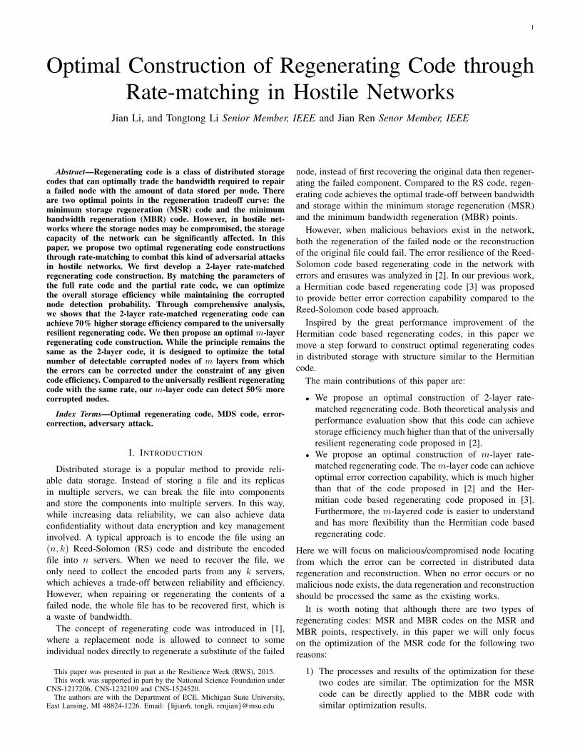
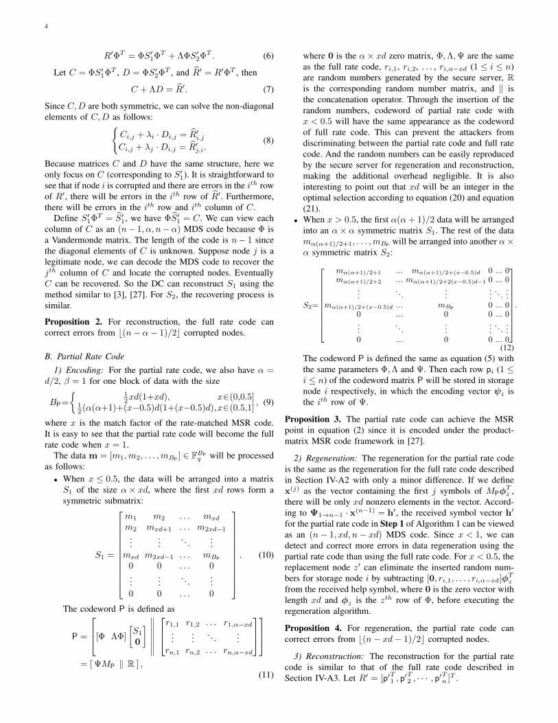
An illustrative example of the 2-layer rate-matched MSRcode with parameters n = 7, d = 4, x = 1/2 is shown inFig. 1. In this example, there are two malicious nodes (Node2 and Node 5) which will send manipulated responses forthe data regeneration of Node 1. According to Proposition 4,during the regeneration of Node 1, the partial rate code candetect and correct the errors in the responses of Node 2 andNode 5. With the malicious nodes information provided bythe partial rate code, the full rate code could be regeneratedcorrectly thereafter. Through this design we could get anoptimal trade-off between the error correction capability andthe storage efficiency, while for the universally resilient MSRcode, improving the error correction capability will cause amuch lower storage efficiency.
D. Parameter Optimization
We have the following design requirements for a givendistributed storage system applying the 2-layer rate-matchedMSR code:• The maximum number of corrupted nodes τ that the
system can detect and locate using the partial rate code.We have
b(n− xd− 1)/2c = τ. (17)
• We use Pdet to represent the probability that the systemcan detect all the corrupted nodes. The detection will besuccessful if each corrupted node modifies at least onehelp symbol corresponding to the partial rate code andsends it to the replacement node. Suppose the probabilitywith which each help symbol is modified by either errorsor malicious manipulations is P , then we have(
1− (1− P)θP)τ ≥ Pdet. (18)
Define the storage efficiency δS as the ratio between theactual size of data to be stored and the total storage spaceneeded by the encoded data. Then we have:
δS =θFBF + θPBP
(θF + θP)nα=
B
(θF + θP)nα. (19)
There is a trade-off between θP the number of data blocksencoded by the partial rate code and θF the number of datablocks encoded by the full rate code. If we encode using toomuch full rate code, we may not meet the detection probabilityPdet requirement. If we employ too much partial rate code, theredundancy of the code may be too high. We can calculate the
optimized parameters x, d, θF, θP by maximizing equation (19)under the constraints defined by equations (14), (15), (17),(18). That is:
maximize equation (19) : δS =B
(θF + θP)nα,
subject to equation (14) : b(n− xd− 1)/2c = n− d− 1,
equation (15) : B = θFBF + θPBP,
equation (17) : b(n− xd− 1)/2c = τ,
equation (18) :(1− (1− P)θP
)τ ≥ Pdet.
For this optimization, d and x can be determined by equation(14) and (17):
d = n− τ − 1, (20)x = (n− 2τ − 1)/(n− τ − 1). (21)
Since B is constant, to maximize δS is equal to minimize θF +θP. So we can rewrite the optimization problem as follows:
minimize θF + θP,
subject to equation (15): B = θFBF + θPBP,
equation (18):(1− (1− P)θP
)τ ≥ Pdet.
(22)
This is a simple linear programming problem. It is straight-forward to derive the optimization results directly:
θP = log(1−P)
(1− P1/τ
det
), (23)
θF = (B − θPBP)/BF. (24)
In this paper we assume that we are storing large files, whichmeans B > θPBP. So an optimal solution for the 2-layerrate-matched MSR code can always be found. We have thefollowing theorem:
Theorem 3. When the number of blocks of the partial ratecode θP equals to log(1−P)
(1− P1/τ
det
)and the number of
blocks of the full rate code θF equals to (B − θPBP)/BF,the 2-layer rate-matched MSR code can achieve the optimalstorage efficiency.
E. Reconstruction
When DC needs to reconstruct the original file, it will sendreconstruction requests to n storage nodes. Upon receivingthe request, node i will send out the symbol vector ci.Suppose c′i = ci + ei is the response from the ith storagenode. If ei ∈ Fα(θP+θF)q \{0}, it means the response ci hasbeen modified, therefore, the node i is corrupted. Since DChas the permutation information of the partial rate code andthe full rate code, similar to the regeneration of the 2-layerrate-matched MSR code, DC will perform the reconstructionusing Algorithm 3.
Algorithm 3. DC reconstructs the original file for the 2-layerrate-matched MSR code.Step 1: According to the permutation information, reconstruct
each of the θP data blocks encoded by the partial ratecode and locate the corrupted nodes.
Step 2: Reconstruct each of the data blocks encoded by thefull rate code. During the reconstruction, all the
7
u1+u2+u4+u5Node 1Fail
u2+u3+u5+u6
u7+u8 u8+u9
u1+2u2+2u4+4u5Node 2Malicious
u2+2u3+2u5+4u6
u7+2u8 u8+2u9
u1+4u2+3u4+12u5
Node 3u2+4u3+3u5+12u6
u7+4u8 u8+4u9
u1+8u2+4u4+6u5
Node 4u2+8u3+4u5+6u6
u7+8u8 u8+8u9
u2+3u3+5u5+2u6
u8+3u9
u2+6u3+6u5+10u6
u8+6u9
u2+12u3+7u5+6u6
u8+12u9
u1+3u2+5u4+2u5
u7+3u8
u1+6u2+6u4+10u5
u7+6u8
u1+12u2+7u4+6u5
u7+12u8
Node 5Malicious
Node 6
Node 7
∙ [1 1]T
∙ [1 1]T
bo symbol
∙ [1 1]T
∙ [1 1]T
∙ [1 1]T
∙ [1 1]T
∙ [1 1]T
∙ [1 1]T
(6,2,5) RS code decoding
bo symbolbo symbol
bo symbol
partial rate code
Regenerationu1+u2+u4+u5 Replacement
Node 1
u2+u3+u5+u6
u7+u8 u8+u9
Regeneration
full rate code
malicious nodes information
partial rate code: full rate code: bogus symbol: bo symbol
Fig. 1. An illustrative example of the 2-layer rate-matched MSR code
symbols sent from corrupted nodes will be replacedby erasures ⊗.
In Section V-D, we optimize the parameters for the dataregeneration, considering the trade-off between the successfulcorrupted node detection probability and the storage efficiency.For data reconstruction, we have the following theorem:
Theorem 4 (Optimal Parameters). When the number of blocksof the partial rate code θP equals to log(1−P)
(1− P1/τ
det
)and
the number of blocks of the full rate code θF equals to (B −θPBP)/BF, the 2-layer rate-matched MSR code can guaranteethat the same constraints for data regeneration (equation (17)and equation (18)) be satisfied for the data reconstruction.
Proof. The maximum number of corrupted nodes that can bedetected for the data reconstruction is calculated as follows:• If x > 0.5, the number is b(n− α− 1)/2c. We haveb(n− α− 1)/2c ≥ b(n− xd− 1)/2c = τ .
• If x ≤ 0.5, the number is b(n− xd)/2c. We haveb(n− xd)/2c ≥ b(n− xd− 1)/2c = τ .
Therefore, in both cases, we can detect the maximum numberof corrupted nodes τ .
The probability for corrupted node to be detected success-fully in the data reconstruction can be calculated as:(
1− (1− P)αθP)τ>(1− (1− P)θP
)τ ≥ Pdet.
Although the rate-matching equation (14) does not applyto the data reconstruction, the reconstruction strategy in Al-gorithm 3 can still benefit from the different rates of the two
codes. When x ≤ 0.5, the partial rate code can detect andcorrect b(n− xd)/2c corrupted nodes, which are more thanb(n− d/2− 1)/2c corrupted nodes that the full rate code candetect. When x > 0.5, the full rate code and the partial ratecode can detect and correct the same number of corruptednodes: b(n− α− 1)/2c.
From the analysis above we can see that the optimizedparameters obtained for the data regeneration can also achievethe optimized trade-off between the corrupted node detectionand storage efficiency for the data reconstruction.
F. Performance Evaluation
From the analysis above, we know that for a distributedstorage system with n storage nodes, out of which at most τnodes are corrupted, the 2-layer rate-matched MSR code canguarantee detection and correction of these nodes during thedata regeneration and reconstruction with the probability atleast Pdet.
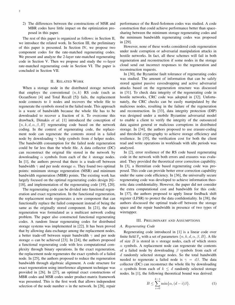
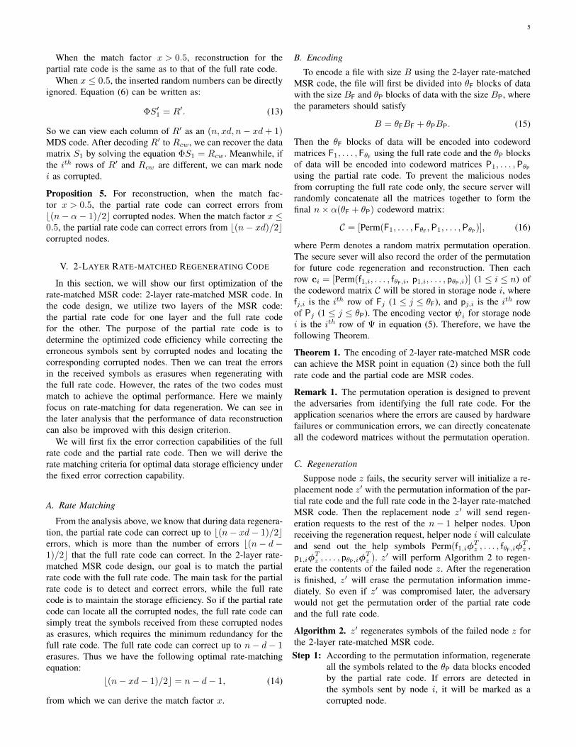
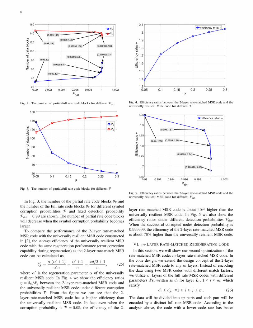
As an example, for a distributed storage system with n =30, τ = 11 and P = 0.2, suppose we have a file with the sizeB = 14000 symbols to be stored in the system. Accordingto the parameter optimization discussed above, we have thematch factor x = 7/18, partial rate code block size BP = 28and full rate code block size BF = 90. The number of thepartial rate code blocks θP and the number of the full ratecode blocks θF for different detection probabilities Pdet areshown in Fig. 2. From the figure we can see that the numberof partial rate code blocks will increase when the detectionprobability becomes larger. Accordingly, the number of fullrate code blocks will decrease.
8
0.99 0.992 0.994 0.996 0.998 1 1.002Pdet
20
40
60
80
100
120
140
160N
umbe
r of d
ata
bloc
ks3P3F
(0.99,146)
(0.999,143)
(0.9999,140)
(0.99999,136) (0.999999,133)
(0.999999,73)(0.99999,63)
(0.9999,53)
(0.999,42)
(0.99,32)
Fig. 2. The number of partial/full rate code blocks for different Pdet
0.05 0.1 0.15 0.2 0.25 0.3P
20
40
60
80
100
120
140
160
Num
ber o
f dat
a bl
ocks
3P3F
Fig. 3. The number of partial/full rate code blocks for different P
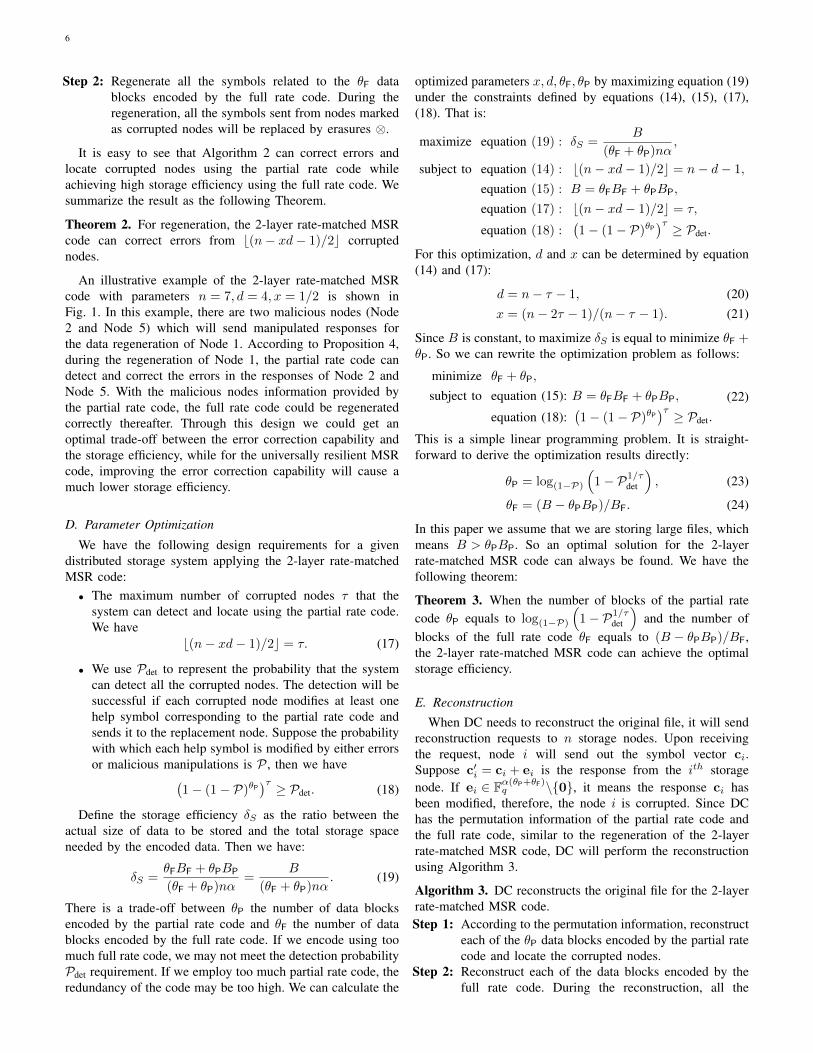
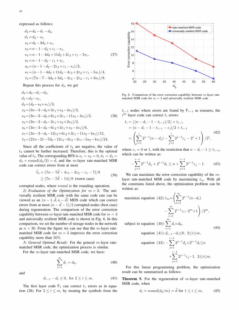
In Fig. 3, the number of the partial rate code blocks θP andthe number of the full rate code blocks θF for different symbolcorruption probabilities P and fixed detection probabilityPdet = 0.99 are shown. The number of partial rate code blockswill decrease when the symbol corruption probability becomeslarger.
To compare the performance of the 2-layer rate-matchedMSR code with the universally resilient MSR code constructedin [2], the storage efficiency of the universally resilient MSRcode with the same regeneration performance (error correctioncapability during regeneration) as the 2-layer rate-match MSRcode can be calculated as
δ′S =α′(α′ + 1)
α′n=α′ + 1
n=xd/2 + 1
n, (25)
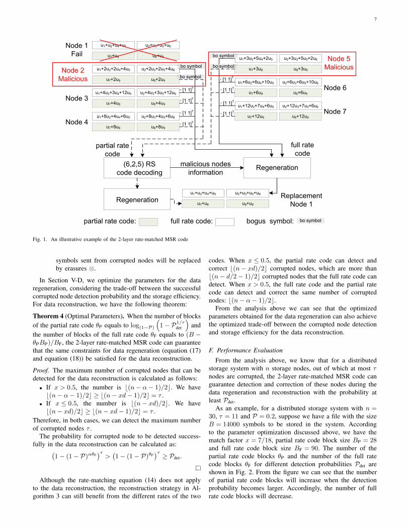
where α′ is the regeneration parameter α of the universallyresilient MSR code. In Fig. 4 we show the efficiency ratiosη = δS/δ
′S between the 2-layer rate-matched MSR code and
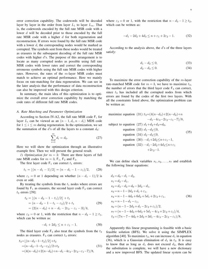
the universally resilient MSR code under different corruptionprobabilities P . From the figure we can see that the 2-layer rate-matched MSR code has a higher efficiency thanthe universally resilient MSR code. In fact, even when thecorruption probability is P = 0.05, the efficiency of the 2-
0.05 0.1 0.15 0.2 0.25 0.3P
1.3
1.4
1.5
1.6
1.7
1.8
1.9
2
2.1
Effic
ienc
y ra
tio 2
efficiency ratio 2
Fig. 4. Efficiency ratios between the 2-layer rate-matched MSR code and theuniversally resilient MSR code for different P
0.99 0.992 0.994 0.996 0.998 1 1.002Pdet
1.65
1.7
1.75
1.8
1.85
1.9
1.95
Effic
ienc
y ra
tio 2
efficiency ration 2
(0.99999, 1.74)
(0.99, 1.95)
(0.999, 1.87)
(0.999999, 1.68)
(0.9999, 1.80)
Fig. 5. Efficiency ratios between the 2-layer rate-matched MSR code and theuniversally resilient MSR code for different Pdet
layer rate-matched MSR code is about 40% higher than theuniversally resilient MSR code. In Fig. 5 we also show theefficiency ratios under different detection probabilities Pdet.When the successful corrupted nodes detection probability is0.999999, the efficiency of the 2-layer rate-matched MSR codeis about 70% higher than the universally resilient MSR code.
VI. m-LAYER RATE-MATCHED REGENERATING CODE
In this section, we will show our second optimization of therate-matched MSR code: m-layer rate-matched MSR code. Inthe code design, we extend the design concept of the 2-layerrate-matched MSR code to any m layers. Instead of encodingthe data using two MSR codes with different match factors,we utilize m layers of the full rate MSR codes with differentparameters d’s, written as di for layer Li, 1 ≤ i ≤ m, whichsatisfy
di ≤ dj , ∀1 ≤ i ≤ j ≤ m. (26)
The data will be divided into m parts and each part will beencoded by a distinct full rate MSR code. According to theanalysis above, the code with a lower code rate has better
9
error correction capability. The codewords will be decodedlayer by layer in the order from layer L1 to layer Lm. Thatis, the codewords encoded by the full rate MSR code with alower d will be decoded prior to those encoded by the fullrate MSR code with a higher d for both regeneration andreconstruction. If errors were found by the full rate MSR codewith a lower d, the corresponding nodes would be marked ascorrupted. The symbols sent from these nodes would be treatedas erasures in the subsequent decoding of the full rate MSRcodes with higher d’s. The purpose of this arrangement is tolocate as many corrupted nodes as possible using full rateMSR codes with lower rates and correct the correspondingerroneous symbols using the full rate MSR codes with higherrates. However, the rates of the m-layer MSR codes mustmatch to achieve an optimal performance. Here we mainlyfocus on rate-matching for data regeneration. We can see inthe later analysis that the performance of data reconstructioncan also be improved with this design criterion.
In summary, the main idea of this optimization is to opti-mize the overall error correction capability by matching thecode rates of different full rate MSR codes.
A. Rate Matching and Parameter Optimization
According to Section IV-A2, the full rate MSR code Fi forlayer Li can be viewed as an (n− 1, di, n− di) MDS codefor 1 ≤ i ≤ m during regeneration. In the optimization, we setthe summation of the d’s of all the layers to a constant d0:
m∑i=1
di = d0. (27)
Here we will show the optimization through an illustrativeexample first. Then we will present the general result.
1) Optimization for m = 3: There are three layers of fullrate MSR codes for m = 3, F1, F2 and F3.
The first layer code F1 can correct t1 errors:
t1 = b(n− d1 − 1)/2c = (n− d1 − 1− ε1)/2, (28)
where ε1 = 0 or 1 depending on whether (n− d1 − 1)/2 iseven or odd.
By treating the symbols from the t1 nodes where errors arefound by F1 as erasures, the second layer code F2 can correctt2 errors [39]:
t2 = b(n− d2 − 1− t1)/2c+ t1
= (n− d2 − 1− t1 − ε2)/2 + t1
= (2(n− d2) + n− d1 − 2ε2 − ε1 − 3)/4,
(29)
where ε2 = 0 or 1, with the restriction that n− d2 − 1 ≥ t1,which can be written as:
−d1 + 2d2 ≤ n+ ε1 − 1. (30)
The third layer code F3 also treat the symbols from the t2nodes as erasures. F3 can correct t3 errors:
t3=b(n−d3−1−t2)/2c+t2=(n−d3−1−t2−ε3)/2+t2
=(4(n−d3)+2(n−d2)+n−d1−4ε3−2ε2−ε1−7)/8,
(31)
where ε3 = 0 or 1, with the restriction that n− d3− 1≥ t2,which can be written as:
−d1− 2d2 + 4d3 ≤ n+ ε1 + 2ε2− 1. (32)
According to the analysis above, the d’s of the three layerssatisfy:
d1− d2 ≤ 0, (33)d2− d3 ≤ 0. (34)
To maximize the error correction capability of the m-layerrate-matched MSR code for m= 3, we have to maximize t3,the number of errors that the third layer code F3 can correct,since t3 has included all the corrupted nodes from whicherrors are found by the codes of the first two layers. Withall the constraints listed above, the optimization problem canbe written as:
maximize equation (31): t3=(4(n−d3)+2(n−d2)+n
−d1−4ε3−2ε2−ε1−7)/8,
subject to equation (27): d1+d2+d3=d0,
equation (33): d1−d2≤0,
equation (34): d2−d3≤0,
equation (30):−d1+2d2≤n+ε1−1,
equation (32):−d1−2d2+4d3≤n+ε1
+2ε2−1.
(35)
We can define slack variables s1, s2, . . . , s7 and establishthe following linear equations:
d3 =d0−d1−d2,s1 =d2−d1,s2 =d3−d2 =d0−2d2−d1,s3 =n−1−2d2 +d1 +ε1,
s4 =n−1−4d0 +6d2 +5d1 +2ε2 +ε1,
s5 =n−1−d1−ε1,s6 =(n−1−2d2 +d1−2ε2 +ε1)/2,
s7 =(n−1−4d0 +6d2 +5d1−4ε3 +2ε2 +ε1)/4,
t3 =(7n−7−4d0 +2d2 +3d1−4ε3−2ε2−ε1)/8.
(36)
Apparently this linear programming is feasible with a basicfeasible solution (BFS). We solve it using the SIMPLEXalgorithm [40]. To maximize t3, we can increase d1 in equation(36), which is a Gaussian elimination of d1 in t3. It is easyto know that as long as d1 does not exceed d2, then afterthe substitution is complete, we will have a new dictionaryand a new improved BFS. The updated linear system can be
10
expressed as follows:
d3 =d0−d1−d2,d1 =d2−s1,s2 =d0−3d2 +s1,
s3 =n−1−d2 +ε1−s1,s4 =n−1−4d0 +11d2 +2ε2 +ε1−5s1,
s5 =n−1−d2−ε1 +s1,
s6 =(n−1−d2−2ε2 +ε1−s1)/2,
s7 =(n−1−4d0 +11d2−4ε3 +2ε2 +ε1−5s1)/4,
t3 =(7n−7−4d0 +5d2−4ε3−2ε2−ε1 +3s1)/8.
(37)
Repeat this process for d2, we get
d3=d0−d1−d2,d1=d2−s1,d2=(d0−s2+s1)/3,
s3=(3n−3−d0+3ε1+s2−4s1)/3,
s4=(3n−3−d0+6ε2+3ε1−11s2−4s1)/3,
s5=(3n−3−d0−3ε1+s2+2s1)/3,
s6=(3n−3−d0−6ε2+3ε1+s2−4s1)/6,
s7=(3n−3−d0−12ε3+6ε2+3ε1−11s2−4s1)/12,
t3=(21n−21−7d0−12ε3−6ε2−3ε1−5s2−4s1)/24.
(38)
Since all the coefficients of t3 are negative, the value oft3 cannot be further increased. Therefore, this is the optimalvalue of t3. The corresponding BFS is s1 = s2 = 0, d1 = d2 =d3 = round(d0/3) = d, and the m-layer rate-matched MSRcode can correct errors from at most
t3 = (7n− 7d− 4ε3 − 2ε2 − ε1 − 7)/8
≥ (7n− 7d− 14)/8 (worst case)(39)
corrupted nodes, where round is the rounding operation.2) Evaluation of the Optimization for m = 3: The uni-
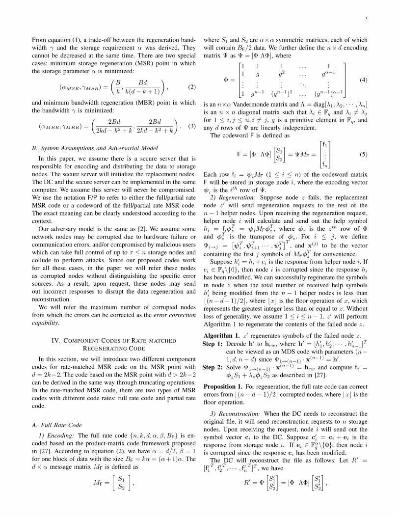
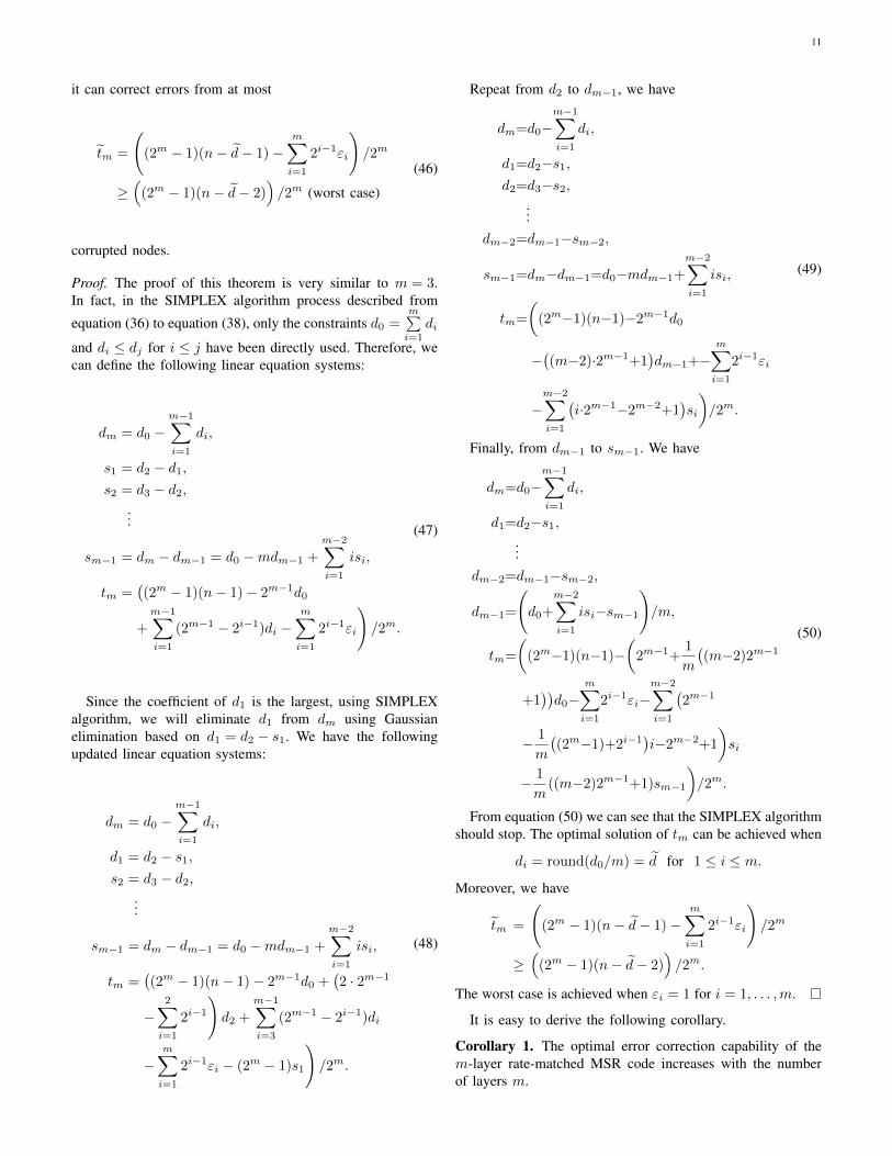
versally resilient MSR code with the same code rate can beviewed as an (n− 1, d, n− d) MDS code which can correcterrors from at most (n− d− 1)/2 corrupted nodes (best case)during regeneration. The comparison of the error correctioncapability between m-layer rate-matched MSR code for m = 3and universally resilient MSR code is shown in Fig. 6. In thiscomparison, we set the number of storage nodes in the networkas n = 30. From the figure we can see that the m-layer rate-matched MSR code for m = 3 improves the error correctioncapability more than 50%.
3) General Optimal Result: For the general m-layer rate-matched MSR code, the optimization process is similar.
For the m-layer rate-matched MSR code, we have:m∑i=1
di = d0, (40)
anddi−1 − di ≤ 0, for 2 ≤ i ≤ m. (41)
The first layer code F1 can correct t1 errors as in equa-tion (28). For 2 ≤ i ≤ m, by treating the symbols from the
20 25 30 35 40 45 50 55 60d0
4
6
8
10
12
14
16
18
Erro
r cor
rect
ion
capa
bilit
y
rate-matched MSR codeuniversally resilient MSR code
Fig. 6. Comparison of the error correction capability between m-layer rate-matched MSR code for m = 3 and universally resilient MSR code
ti−1 nodes where errors are found by Fi−1 as erasures, theith layer code can correct ti errors:
ti = b(n− di − 1− ti−1)/2c+ ti−1
= (n− di − 1− ti−1 − εi)/2 + ti−1
=
i∑j=1
2j−1(n− dj)−i∑
j=1
2j−1εj − 2i + 1
/2i,
(42)
where εi = 0 or 1, with the restriction that n− di − 1 ≥ ti−1,which can be written as:
−i−1∑j=1
2j−1dj + 2i−1di ≤ n+
i−1∑j=1
2j−1εj − 1. (43)
We can maximize the error correction capability of the m-layer rate-matched MSR code by maximizing tm. With allthe constrains listed above, the optimization problem can bewritten as:
maximize equation (42): tm=
(m∑i=1
2i−1(n−di)
−m∑i=1
2i−1εi−2m+1
)/2m,
subject to equation (40):
m∑i=1
di=d0,
equation (41): di−1−di≤0, 2≤i≤m,
equation (43):−i−1∑j=1
2j−1dj+2i−1di≤n
+
i−1∑j=1
2j−1εj−1, 2≤i≤m.
(44)
For this linear programming problem, the optimizationresult can be summarized as follows:
Theorem 5. For the regeneration of m-layer rate-matchedMSR code, when
di = round(d0/m) = d for 1 ≤ i ≤ m, (45)
11
it can correct errors from at most
tm =
((2m − 1)(n− d− 1)−
m∑i=1
2i−1εi
)/2m
≥(
(2m − 1)(n− d− 2))/2m (worst case)
(46)
corrupted nodes.
Proof. The proof of this theorem is very similar to m = 3.In fact, in the SIMPLEX algorithm process described from
equation (36) to equation (38), only the constraints d0 =m∑i=1
di
and di ≤ dj for i ≤ j have been directly used. Therefore, wecan define the following linear equation systems:
dm = d0 −m−1∑i=1
di,
s1 = d2 − d1,s2 = d3 − d2,
...
sm−1 = dm − dm−1 = d0 −mdm−1 +
m−2∑i=1
isi,
tm =((2m − 1)(n− 1)− 2m−1d0
+
m−1∑i=1
(2m−1 − 2i−1)di −m∑i=1
2i−1εi
)/2m.
(47)
Since the coefficient of d1 is the largest, using SIMPLEXalgorithm, we will eliminate d1 from dm using Gaussianelimination based on d1 = d2 − s1. We have the followingupdated linear equation systems:
dm = d0 −m−1∑i=1
di,
d1 = d2 − s1,s2 = d3 − d2,
...
sm−1 = dm − dm−1 = d0 −mdm−1 +
m−2∑i=1
isi,
tm =((2m − 1)(n− 1)− 2m−1d0 +
(2 · 2m−1
−2∑i=1
2i−1
)d2 +
m−1∑i=3
(2m−1 − 2i−1)di
−m∑i=1
2i−1εi − (2m − 1)s1
)/2m.
(48)
Repeat from d2 to dm−1, we have
dm=d0−m−1∑i=1
di,
d1=d2−s1,d2=d3−s2,
...dm−2=dm−1−sm−2,
sm−1=dm−dm−1=d0−mdm−1+
m−2∑i=1
isi,
tm=
((2m−1)(n−1)−2m−1d0
−((m−2)·2m−1+1
)dm−1+−
m∑i=1
2i−1εi
−m−2∑i=1
(i·2m−1−2m−2+1
)si
)/2m.
(49)
Finally, from dm−1 to sm−1. We have
dm=d0−m−1∑i=1
di,
d1=d2−s1,...
dm−2=dm−1−sm−2,
dm−1=
(d0+
m−2∑i=1
isi−sm−1
)/m,
tm=
((2m−1)(n−1)−
(2m−1+
1
m
((m−2)2m−1
+1))d0−
m∑i=1
2i−1εi−m−2∑i=1
(2m−1
− 1
m
((2m−1)+2i−1
)i−2m−2+1
)si
− 1
m((m−2)2m−1+1)sm−1
)/2m.
(50)
From equation (50) we can see that the SIMPLEX algorithmshould stop. The optimal solution of tm can be achieved when
di = round(d0/m) = d for 1 ≤ i ≤ m.
Moreover, we have
tm =
((2m − 1)(n− d− 1)−
m∑i=1
2i−1εi
)/2m
≥(
(2m − 1)(n− d− 2))/2m.
The worst case is achieved when εi = 1 for i = 1, . . . ,m.
It is easy to derive the following corollary.
Corollary 1. The optimal error correction capability of them-layer rate-matched MSR code increases with the numberof layers m.
12
Proof. From equation (46), the error correction capability canbe further written as:(
1− 1
2m
)(n− round
(d0m
)− 2
)≤ tm
≤(
1− 1
2m
)(n− round
(d0m
)− 1
),
(51)
where both sides increase with m, and the difference betweenthe two sides is at most 1. Based on this observation, it is easyto prove that tm also increases with m.
Remark 2. Although the m-layer rate-matched MSR codeshares the same principle with the 2-layer code, it is not adirect extension of the 2-layer code for three reasons: First,the application scenario and optimization goals for the m-layer rate-matched MSR code are different from the 2-layerrate-matched MSR code. The 2-layer code is designed tooptimize the storage efficiency under the constraint of anypredetermined error correction capability, while the m-layercode is designed to optimize the overall error correctioncapability under the constraint of any giving code efficiency.Second, under the same comparable optimization constrains,the error correction capability of the 2-layer code is muchworse than the m-layer rate-matched MSR code. Third, the m-layer rate-matched MSR code is more secure under maliciousattacks than the direct generalization from the 2-layer codedue to the more diversified structure.
4) Optimal Code Rate - Dual of Optimal Error Correction:During the optimization, we set the code rate of the rate-matched MSR code to a constant value and maximize the errorcorrection capability. To optimize the rate-matched MSR code,we can also set the error correction capability ti for i = m inequation (42) to a constant value
tm =
(m∑i=1
2i−1(n− di)−m∑i=1
2i−1εi − 2m + 1
)/2m = t0,
(52)and maximize the code rate during regeneration. The problemcan be written as:
maximizem∑i=1
di,
subject to equation (43) :−i−1∑j=1
2j−1dj+2i−1di≤n
+
i−1∑j=1
2j−1εj−1, 2≤ i≤m,
equation (41) : di−1−di≤0, 2≤ i≤m,equation (52) : tm= t0.
(53)
The optimization result is the same as that of equation (44).That is when all the d′is for 1 ≤ i ≤ m are the same, the coderate is maximized. More specifically, we have:
di = n− 1−
(2mt0 +
m∑i=1
2i−1εi
)/(2m − 1)
≥ n− 2− 2mt02m − 1
(worst case).
(54)
4 6 8 10 12 14 16q
0
20
40
60
80
100
120
140
Erro
r cor
rect
ion
capa
bilit
y
rate-matched MSR codeH-MSR codeuniversally resilient MSR code
Fig. 7. Comparison of error correction capability between the m-layer ratematched MSR code and the H-MSR code
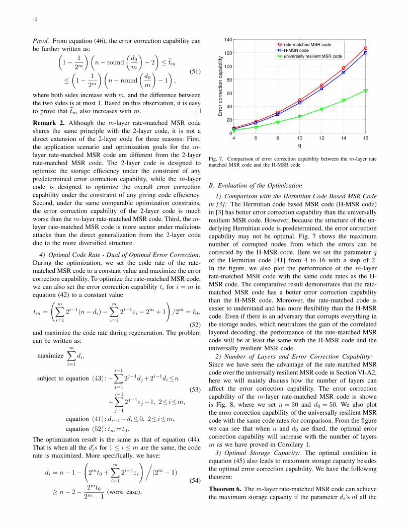
B. Evaluation of the Optimization
1) Comparison with the Hermitian Code Based MSR Codein [3]: The Hermitian code based MSR code (H-MSR code)in [3] has better error correction capability than the universallyresilient MSR code. However, because the structure of the un-derlying Hermitian code is predetermined, the error correctioncapability may not be optimal. Fig. 7 shows the maximumnumber of corrupted nodes from which the errors can becorrected by the H-MSR code. Here we set the parameter qof the Hermitian code [41] from 4 to 16 with a step of 2.In the figure, we also plot the performance of the m-layerrate-matched MSR code with the same code rates as the H-MSR code. The comparative result demonstrates that the rate-matched MSR code has a better error correction capabilitythan the H-MSR code. Moreover, the rate-matched code iseasier to understand and has more flexibility than the H-MSRcode. Even if there is an adversary that corrupts everything inthe storage nodes, which neutralizes the gain of the correlatedlayered decoding, the performance of the rate-matched MSRcode will be at least the same with the H-MSR code and theuniversally resilient MSR code.
2) Number of Layers and Error Correction Capability:Since we have seen the advantage of the rate-matched MSRcode over the universally resilient MSR code in Section VI-A2,here we will mainly discuss how the number of layers canaffect the error correction capability. The error correctioncapability of the m-layer rate-matched MSR code is shownis Fig. 8, where we set n = 30 and d0 = 50. We also plotthe error correction capability of the universally resilient MSRcode with the same code rates for comparison. From the figurewe can see that when n and d0 are fixed, the optimal errorcorrection capability will increase with the number of layersm as we have proved in Corollary 1.
3) Optimal Storage Capacity: The optimal condition inequation (45) also leads to maximum storage capacity besidesthe optimal error correction capability. We have the followingtheorem:
Theorem 6. The m-layer rate-matched MSR code can achievethe maximum storage capacity if the parameter di’s of all the

13
2 4 6 8 10 12 14 16m
0
5
10
15
20
25
30Er
ror c
orre
ctio
n ca
pabi
lity
rate-matched MSR codeuniversally resilient MSR code
Fig. 8. The optimal error correction capability of the m-layer rate-matchedMSR code under different m for 2 ≤ m ≤ 16
layers are the same, under the constraint in equation (27).
Proof. The code of the ith layer can store one block of datawith the size Bi = αi(αi + 1) = (di/2)(di/2 + 1). So the m-
layer code can store data with the size B =m∑i=1
(di/2)(di/2 +
1). Our goal here is to maximize B under the constraint inequation (27).
We can use Lagrange multipliers to find the point ofmaximum B. Let
ΛL(d1, . . . , dm, λ) =
m∑i=1
(di/2)(di/2 + 1) + λ
(m∑i=1
di − d0
).
(55)We can find the maximum value of B by setting the partialderivatives of this equation to zero:
∂ΛL∂di
=di + 1
2+ λ = 0, ∀1 ≤ i ≤ m. (56)
Here we can see that when all the parameter d’s of all thelayers are the same, we can get the maximum storage capacityB. This maximization condition coincides with the optimalcondition for achieving the goal of this section: optimizingthe overall error correction capability of the rate-matched MSRcode.
C. Practical Consideration of the OptimizationSo far, we implicitly presume that there is only one data
block of the size Bi = αi(αi + 1) for each layer i. In practicaldistributed storage, it is the parameter di that is fixed insteadof d0, the summation of di. However, as long as we use mlayers of MSR codes with the same parameter d = d, we willstill get the optimal solution for d0 = md. In fact, the m-layerrate-matched MSR code here becomes a single full rate MSRcode with parameter d = d and m data blocks. And based onthe dependent decoding idea we describe at the beginning ofSection VI, we can achieve the optimal performance.
So when the file size B is larger than one data block sizeB of the single full rate MSR code with parameter d = d, wewill divide the file into dB/Be data blocks and encode themseparately. If we decode these data blocks dependently, we canget the optimal error correction capability.
2 3 4 5 6 7 8m
14
16
18
20
22
24
Erro
r cor
rect
ion
capa
bilit
y
ed =5
ed=10
Fig. 9. The optimal error correction capability for 2 ≤ m ≤ 8
1) Evaluation of the Optimal Error Correction Capability:In the practical case, d could be fixed. So here we willstudy the relationship between the number of dependentlydecoding data blocks m and the error correction capability,which is shown in Fig. 9. In the figure, we set n = 30and d = 5, 10, respectively. From the figure we can see thatalthough the error correction capability will become higherwith the increasing of dependently decoding data blocks m, theamount of improvement will be negligible for m ≥ 5. Actuallywhen m = 5 the capability has already achieved the upperbound.
On the other hand, there exist parallel algorithms for fastMDS code decoding [42]. We can decode blocks of MDScodewords parallel in a pipeline fashion to accelerate the over-all decoding speed. The more blocks of codewords we decodeparallel, the faster we will finish the whole decoding process.For large files that could be divided into a large amount of datablocks (θ blocks), we can get a trade-off between the optimalerror correction capability and the decoding speed by settingthe number of dependent decoding data blocks m and thenumber of parallel decoding data blocks ρ under the constraintθ = mρ.
D. Encoding
From the analysis above we know that to encode a filewith size B using the optimal m-layer rate-matched MSRcode is to encode the file using a full rate MSR code withpredetermined parameter d = 2α = d. First the file will bedivided into θ blocks of data with size B, where θ = dB/Be .Then the θ blocks of data will be encoded into codeword ma-trices F1, . . . ,Fθ and form the final n× αθ codeword matrix:C = [F1, . . . ,Fθ]. Each row ci = [f1,i, . . . , fθ,i], 1 ≤ i ≤ n, ofthe codeword matrix C will be stored in storage node i, wherefj,i is the ith row of Fj , 1 ≤ j ≤ θ. The encoding vector ψifor storage node i is the ith row of Ψ in equation (5).
Theorem 7. The encoding of m-layer rate-matched MSR codecan achieve the MSR point in equation (2) since each layer ofthe code is an MSR code.
14
data block 1
data block 2
data block ρ
data block ρ+1
data block ρ+2
data block 2ρ
data block (m-1)ρ+1
data block (m-1)ρ+2
data block mρ
Layer 1
Layer 2
Layer m
Paralleldecodethe row
Paralleldecodethe row
Paralleldecodethe row
Paralleldecodethe row
Dependently
decodethe column
Dependently
decodethe column
Dependently
decodethe column
Dependently
decodethe column
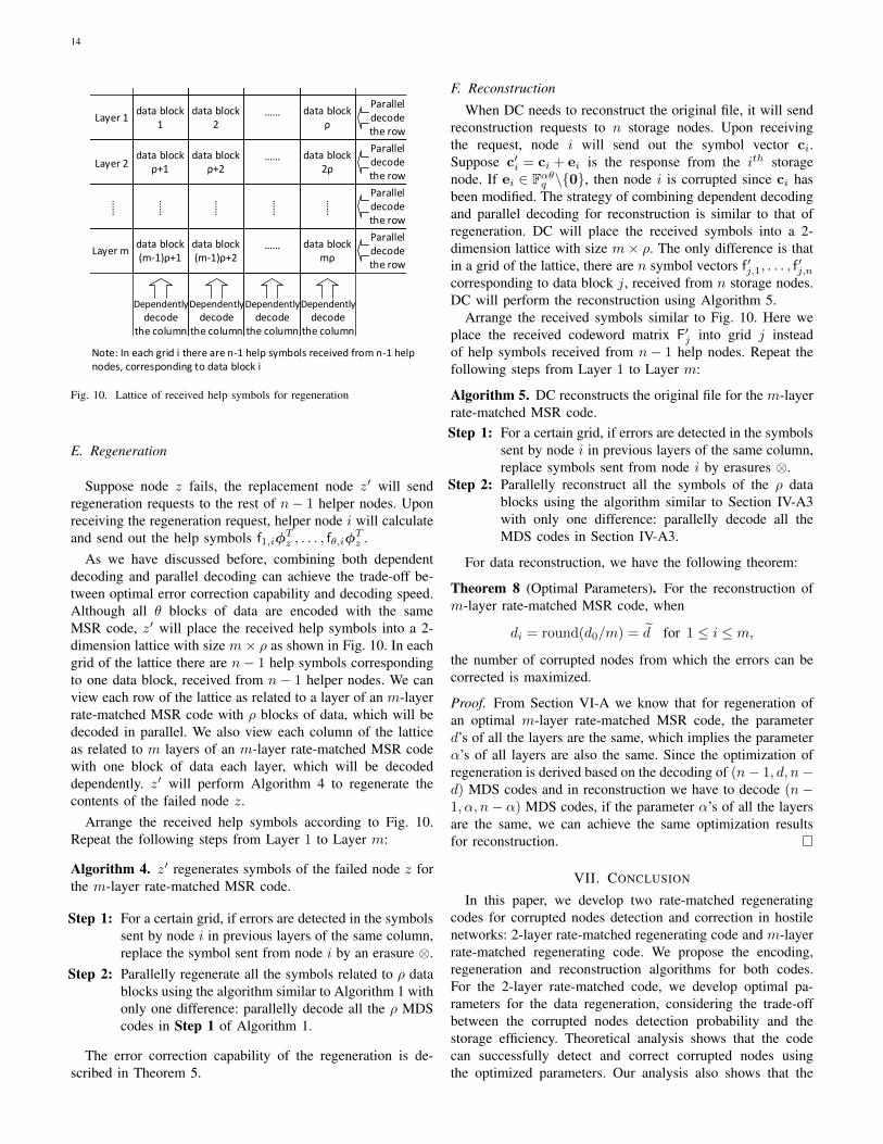
Note: In each grid i there are n-1 help symbols received from n-1 help nodes, corresponding to data block i
Fig. 10. Lattice of received help symbols for regeneration
E. Regeneration
Suppose node z fails, the replacement node z′ will sendregeneration requests to the rest of n− 1 helper nodes. Uponreceiving the regeneration request, helper node i will calculateand send out the help symbols f1,iφ
Tz , . . . , fθ,iφ
Tz .
As we have discussed before, combining both dependentdecoding and parallel decoding can achieve the trade-off be-tween optimal error correction capability and decoding speed.Although all θ blocks of data are encoded with the sameMSR code, z′ will place the received help symbols into a 2-dimension lattice with size m× ρ as shown in Fig. 10. In eachgrid of the lattice there are n− 1 help symbols correspondingto one data block, received from n− 1 helper nodes. We canview each row of the lattice as related to a layer of an m-layerrate-matched MSR code with ρ blocks of data, which will bedecoded in parallel. We also view each column of the latticeas related to m layers of an m-layer rate-matched MSR codewith one block of data each layer, which will be decodeddependently. z′ will perform Algorithm 4 to regenerate thecontents of the failed node z.
Arrange the received help symbols according to Fig. 10.Repeat the following steps from Layer 1 to Layer m:
Algorithm 4. z′ regenerates symbols of the failed node z forthe m-layer rate-matched MSR code.
Step 1: For a certain grid, if errors are detected in the symbolssent by node i in previous layers of the same column,replace the symbol sent from node i by an erasure ⊗.
Step 2: Parallelly regenerate all the symbols related to ρ datablocks using the algorithm similar to Algorithm 1 withonly one difference: parallelly decode all the ρ MDScodes in Step 1 of Algorithm 1.
The error correction capability of the regeneration is de-scribed in Theorem 5.
F. Reconstruction
When DC needs to reconstruct the original file, it will sendreconstruction requests to n storage nodes. Upon receivingthe request, node i will send out the symbol vector ci.Suppose c′i = ci + ei is the response from the ith storagenode. If ei ∈ Fαθq \{0}, then node i is corrupted since ci hasbeen modified. The strategy of combining dependent decodingand parallel decoding for reconstruction is similar to that ofregeneration. DC will place the received symbols into a 2-dimension lattice with size m× ρ. The only difference is thatin a grid of the lattice, there are n symbol vectors f ′j,1, . . . , f
′j,n
corresponding to data block j, received from n storage nodes.DC will perform the reconstruction using Algorithm 5.
Arrange the received symbols similar to Fig. 10. Here weplace the received codeword matrix F′j into grid j insteadof help symbols received from n− 1 help nodes. Repeat thefollowing steps from Layer 1 to Layer m:
Algorithm 5. DC reconstructs the original file for the m-layerrate-matched MSR code.Step 1: For a certain grid, if errors are detected in the symbols
sent by node i in previous layers of the same column,replace symbols sent from node i by erasures ⊗.
Step 2: Parallelly reconstruct all the symbols of the ρ datablocks using the algorithm similar to Section IV-A3with only one difference: parallelly decode all theMDS codes in Section IV-A3.
For data reconstruction, we have the following theorem:
Theorem 8 (Optimal Parameters). For the reconstruction ofm-layer rate-matched MSR code, when
di = round(d0/m) = d for 1 ≤ i ≤ m,
the number of corrupted nodes from which the errors can becorrected is maximized.
Proof. From Section VI-A we know that for regeneration ofan optimal m-layer rate-matched MSR code, the parameterd’s of all the layers are the same, which implies the parameterα’s of all layers are also the same. Since the optimization ofregeneration is derived based on the decoding of (n− 1, d, n−d) MDS codes and in reconstruction we have to decode (n−1, α, n− α) MDS codes, if the parameter α’s of all the layersare the same, we can achieve the same optimization resultsfor reconstruction.
VII. CONCLUSION
In this paper, we develop two rate-matched regeneratingcodes for corrupted nodes detection and correction in hostilenetworks: 2-layer rate-matched regenerating code and m-layerrate-matched regenerating code. We propose the encoding,regeneration and reconstruction algorithms for both codes.For the 2-layer rate-matched code, we develop optimal pa-rameters for the data regeneration, considering the trade-offbetween the corrupted nodes detection probability and thestorage efficiency. Theoretical analysis shows that the codecan successfully detect and correct corrupted nodes usingthe optimized parameters. Our analysis also shows that the

15
code has higher storage efficiency compared to the universallyresilient regenerating code (70% higher for the detectionprobability 0.999999). Then based on the same motivationof “previous errors could be viewed as current erasures”, wepropose the m-layer code and develop parameters to optimizethe overall error correction capability by matching the coderate of each layer’s regenerating code. Theoretical analysisshows that the optimized parameter could also achieve themaximum storage capacity under the same constraint, whichis consistent with the optimization goal of the 2-layer code.Furthermore, analysis shows that compared to the universallyresilient regenerating code, our m-layer code can improve theerror correction capability more than 50%.
ACKNOWLEDGE
The authors would like to thank the anonymous referees fortheir valuable comments, which greatly improved the qualityof the presentation.
REFERENCES
[1] A. Dimakis, P. Godfrey, Y. Wu, M. Wainwright, and K. Ramchandran,“Network coding for distributed storage systems,” IEEE Transactionson Information Theory, vol. 56, pp. 4539 – 4551, 2010.
[2] K. Rashmi, N. Shah, K. Ramchandran, and P. Kumar, “Regeneratingcodes for errors and erasures in distributed storage,” in InternationalSymposium on Information Theory (ISIT) 2012, 2012, pp. 1202–1206.
[3] J. Li, T. Li, and J. Ren, “Beyond the mds bound in distributed cloudstorage,” in INFOCOM, 2014 Proceedings IEEE, April 2014, pp. 307–315.
[4] S. Rhea, C. Wells, P. Eaton, D. Geels, B. Zhao, H. Weatherspoon, andJ. Kubiatowicz, “Maintenance-free global data storage,” IEEE InternetComputing, vol. 5, pp. 40 – 49, 2001.
[5] R. Bhagwan, K. Tati, Y.-C. Cheng, S. Savage, and G. M. Voelker, “Totalrecall: System support for automated availability management,” in roc.Symp. Netw. Syst. Design Implementation, 2004, pp. 337–350.
[6] D. Cullina, A. G. Dimakis, and T. Ho, “Searching for minimum storageregenerating codes,” Available:arXiv:0910.2245, 2009.
[7] N. Shah, K. Rashmi, P. Kumar, and K. Ramchandran, “Explicit codesminimizing repair bandwidth for distributed storage,” in InformationTheory Workshop (ITW), 2010 IEEE, 2010, pp. 1–5.
[8] C. Suh and K. Ramchandran, “Exact-repair mds codes for distributedstorage using interference alignment,” in 2010 IEEE International Sym-posium on Information Theory Proceedings (ISIT), 2010, pp. 161–165.
[9] Y. Wu, “A construction of systematic mds codes with minimum repairbandwidth,” IEEE Transactions on Information Theory, vol. 57, no. 6,pp. 3738–3741, 2011.
[10] D. Papailiopoulos, J. Luo, A. Dimakis, C. Huang, and J. Li, “Simpleregenerating codes: Network coding for cloud storage,” in INFOCOM,2012 Proceedings IEEE, 2012, pp. 2801–2805.
[11] S. El Rouayheb and K. Ramchandran, “Fractional repetition codes forrepair in distributed storage systems,” in 2010 48th Annual AllertonConference on Communication, Control, and Computing (Allerton),2010, pp. 1510–1517.
[12] I. Tamo, Z. Wang, and J. Bruck, “Mds array codes with optimalrebuilding,” in 2011 IEEE International Symposium on InformationTheory Proceedings (ISIT), 2011, pp. 1240–1244.
[13] V. R. Cadambe, C. Huang, S. A. Jafar, and J. Li, “Optimal repair ofmds codes in distributed storage via subspace interference alignment,”Available:arXiv:1106.1250, 2011.
[14] D. Papailiopoulos, A. Dimakis, and V. Cadambe, “Repair optimal erasurecodes through hadamard designs,” IEEE Transactions on InformationTheory, vol. 59, no. 5, pp. 3021–3037, 2013.
[15] N. Shah, K. V. Rashmi, and P. Kumar, “A flexible class of regeneratingcodes for distributed storage,” in 2010 IEEE International Symposiumon Information Theory Proceedings (ISIT), 2010, pp. 1943–1947.
[16] K. Shum and Y. Hu, “Existence of minimum-repair-bandwidth cooper-ative regenerating codes,” in 2011 International Symposium on NetworkCoding (NetCod), 2011, pp. 1–6.
[17] A. Wang and Z. Zhang, “Exact cooperative regenerating codes withminimum-repair-bandwidth for distributed storage,” in INFOCOM, 2013Proceedings IEEE, 2013, pp. 400–404.
[18] C. Tian and T. Liu, “Multilevel diversity coding with regeneration,”IEEE Transactions on Information Theory, vol. 62, no. 9, pp. 4833–4847, 2016.
[19] H. Hou, K. W. Shum, M. Chen, and H. Li, “Basic regenerating code:Binary addition and shift for exact repair,” in 2013 IEEE InternationalSymposium on Information Theory Proceedings (ISIT), 2013, pp. 1621–1625.
[20] Y.-L. Chen, G.-M. Li, C.-T. Tsai, S.-M. Yuan, and H.-T. Chiao, “Re-generating code based p2p storage scheme with caching,” in ICCIT ’09.Fourth International Conference on Computer Sciences and Conver-gence Information Technology, 2009, 2009, pp. 927–932.
[21] Y. Wu, A. G. Dimakis, and K. Ramchandran, “Deterministic regenerat-ing codes for distributed storage,” in 45th Annu. Allerton Conf. Control,Computing, and Communication, 2007.
[22] A. Duminuco and E. Biersack, “A practical study of regeneratingcodes for peer-to-peer backup systems,” in ICDCS ’09. 29th IEEEInternational Conference on Distributed Computing Systems, 2009, June2009, pp. 376 – 384.
[23] K. Shum, “Cooperative regenerating codes for distributed storage sys-tems,” in 2011 IEEE International Conference on Communications(ICC), 2011, pp. 1–5.
[24] H. Hou, K. W. Shum, M. Chen, and H. Li, “Basic codes: Low-complexity regenerating codes for distributed storage systems,” IEEETransactions on Information Theory, vol. 62, no. 6, pp. 3053–3069,2016.
[25] Y. Wu and A. G. Dimakis, “Reducing repair traffic for erasure coding-based storage via interference alignment,” in IEEE International Sym-posium on Information Theory, 2009. ISIT 2009., 2009, pp. 2276–2280.
[26] N. Shah, K. Rashmi, P. Kumar, and K. Ramchandran, “Interferencealignment in regenerating codes for distributed storage: Necessity andcode constructions,” IEEE Transactions on Information Theory, vol. 58,pp. 2134 – 2158, 2012.
[27] K. Rashmi, N. Shah, and P. Kumar, “Optimal exact-regenerating codesfor distributed storage at the msr and mbr points via a product-matrixconstruction,” IEEE Transactions on Information Theory, vol. 57, pp.5227–5239, 2011.
[28] V. Guruswami and M. Wootters, “Repairing reed-solomon codes,” http://arxiv.org/abs/1509.04764, 2016.
[29] C. Tian, B. Sasidharan, V. Aggarwal, V. A. Vaishampayan, and P. V.Kumar, “Layered exact-repair regenerating codes via embedded errorcorrection and block designs,” IEEE Transactions on Information The-ory, vol. 61, no. 4, pp. 1933–1947, 2015.
[30] F. Oggier and A. Datta, “Byzantine fault tolerance of regeneratingcodes,” in 2011 IEEE International Conference on Peer-to-Peer Com-puting (P2P), 2011, pp. 112–121.
[31] S. Pawar, S. El Rouayheb, and K. Ramchandran, “Securing dynamic dis-tributed storage systems against eavesdropping and adversarial attacks,”IEEE Transactions on Information Theory, vol. 57, pp. 6734 – 6753,2011.
[32] Y. Han, R. Zheng, and W. H. Mow, “Exact regenerating codes forbyzantine fault tolerance in distributed storage,” in Proceedings IEEEINFOCOM, 2012, pp. 2498 – 2506.
[33] H. Chen and P. Lee, “Enabling data integrity protection in regenerating-coding-based cloud storage,” in 2012 IEEE 31st Symposium on ReliableDistributed Systems (SRDS), 2012, pp. 51–60.
[34] C. Cachin and S. Tessaro, “Optimal resilience for erasure-coded byzan-tine distributed storage,” in DSN 2006. International Conference onDependable Systems and Networks, 2006, 2006, pp. 115–124.
[35] M. Abd-El-Malek, G. Ganger, G. Goodson, M. Reiter, and J. Wylie,“Lazy verification in fault-tolerant distributed storage systems,” in SRDS2005. 24th IEEE Symposium on Reliable Distributed Systems, 2005,2005, pp. 179–190.
[36] N. B. Shah, K. V. Rashmi, K. Ramchandran, and P. V. Kumar,“Privacy-preserving and secure distributed storage codes,” http://www.eecs.berkeley.edu/∼nihar/publications/privacy security.pdf/ .
[37] J. Li, T. Li, and J. Ren, “Secure regenerating code,” in IEEE GLOBE-COM 2014, 2014, pp. 770–774.
[38] R. Tandon, S. Amuru, T. C. Clancy, and R. M. Buehrer, “Toward optimalsecure distributed storage systems with exact repair,” IEEE Transactionson Information Theory, vol. 62, no. 6, pp. 3477–3492, 2016.
[39] S. Lin and D. J. C. Jr., Error Control Coding. 2nd ed. New Jersey:Prentice Hall.
[40] T. H. Cormen, C. E. Leiserson, R. L. Rivest, and C. Stein, Introductionto Algorithms, 3rd ed. The MIT Press, 2009.
16
[41] J. Ren, “On the structure of hermitian codes and decoding for bursterrors,” IEEE Transactions on Information Theory, vol. 50, pp. 2850–2854, 2004.
[42] D. Dabiri and I. Blake, “Fast parallel algorithms for decoding reed-solomon codes based on remainder polynomials,” IEEE Transactionson Information Theory, vol. 41, no. 4, pp. 873–885, Jul 1995.
Jian Li received the BS and MS degrees both in electrical engineering fromTsinghua University, China in 2005 and 2008 respectively, and the PhD degreein electrical engineering from Michigan State University, East Lansing in2015. He is an assistant professor in the School of Electronic and InformationEngineering, Beijing Jiaotong University, China. His current research interestsinclude network security, cloud storage, wireless sensor network in Internetof things, privacy-preserving communications, and cognitive networks.
Jian Ren (SM’09) received the BS and MS degrees both in mathematics fromShaanxi Normal University, and received the Ph.D. degree in EE from XidianUniversity, China. He is an Associate Professor in the Department of ECEat Michigan State University. His current research interests include networksecurity, cloud computing security, privacy-preserving communications, dis-tributed network storage, and Internet of Things. He is a recipient of the USNational Science Foundation Faculty Early Career Development (CAREER)award in 2009. Dr. Ren is the TPC Chair of IEEE ICNC’17 and GeneralChair of ICNC’18. Dr. Ren is a senior member of the IEEE.
Tongtong Li (SM’08) Tongtong Li received her Ph.D. degree in ElectricalEngineering in 2000 from Auburn University. She is currently an AssociateProfessor in the Depart- ment of Electrical and Computer Engineering atMichigan State University. Her research interests fall into the areas of com-munication system design and networking, wireless security, and statisticalsignal processing, with applications in computational neu- roscience. Dr. Liis currently serving as an Associate Editor for IEEE Transactions on SignalProcessing. She is a recipient of the National Science Foundation (NSF)CAREER Award and a senior member of the IEEE.