Embed Size (px)
Citation preview
86
Repair Parts and Maintenance Guide
The information contained in this document is subject to change without notice.
1514
18A
2
18B 18C
19A 19B 19C19D 19D 19D
3
1
5
8
7A
17
12
9
13
4
16
6
7
20
Optima® Sloan Flushometer
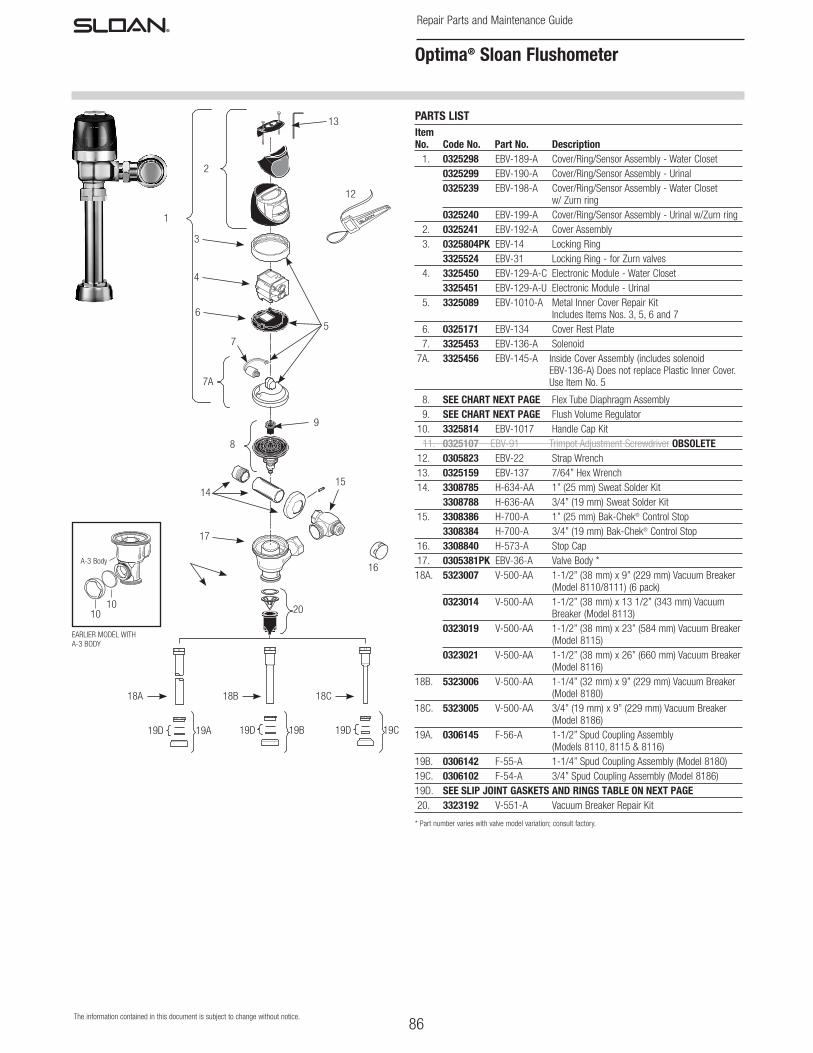
PARTS LISTItem No. Code No. Part No. Description 1. 0325298 EBV-189-A Cover/Ring/Sensor Assembly - Water Closet 0325299 EBV-190-A Cover/Ring/Sensor Assembly - Urinal 0325239 EBV-198-A Cover/Ring/Sensor Assembly - Water Closet
w/ Zurn ring 0325240 EBV-199-A Cover/Ring/Sensor Assembly - Urinal w/Zurn ring 2. 0325241 EBV-192-A Cover Assembly 3. 0325804PK EBV-14 Locking Ring 3325524 EBV-31 Locking Ring - for Zurn valves 4. 3325450 EBV-129-A-C Electronic Module - Water Closet 3325451 EBV-129-A-U Electronic Module - Urinal 5. 3325089 EBV-1010-A Metal Inner Cover Repair Kit Includes Items Nos. 3, 5, 6 and 7 6. 0325171 EBV-134 Cover Rest Plate 7. 3325453 EBV-136-A Solenoid 7A. 3325456 EBV-145-A Inside Cover Assembly (includes solenoid
EBV-136-A) Does not replace Plastic Inner Cover. Use Item No. 5
8. SEE CHART NEXT PAGE Flex Tube Diaphragm Assembly 9. SEE CHART NEXT PAGE Flush Volume Regulator 10. 3325814 EBV-1017 Handle Cap Kit 11. 0325107 EBV-91 Trimpot Adjustment Screwdriver OBSOLETE 12. 0305823 EBV-22 Strap Wrench 13. 0325159 EBV-137 7/64” Hex Wrench 14. 3308785 H-634-AA 1” (25 mm) Sweat Solder Kit 3308788 H-636-AA 3/4” (19 mm) Sweat Solder Kit 15. 3308386 H-700-A 1” (25 mm) Bak-Chek® Control Stop 3308384 H-700-A 3/4” (19 mm) Bak-Chek® Control Stop 16. 3308840 H-573-A Stop Cap 17. 0305381PK EBV-36-A Valve Body * 18A. 5323007 V-500-AA 1-1/2” (38 mm) x 9” (229 mm) Vacuum Breaker
(Model 8110/8111) (6 pack) 0323014 V-500-AA 1-1/2” (38 mm) x 13 1/2” (343 mm) Vacuum
Breaker (Model 8113) 0323019 V-500-AA 1-1/2” (38 mm) x 23” (584 mm) Vacuum Breaker
(Model 8115) 0323021 V-500-AA 1-1/2” (38 mm) x 26” (660 mm) Vacuum Breaker
(Model 8116) 18B. 5323006 V-500-AA 1-1/4” (32 mm) x 9” (229 mm) Vacuum Breaker
(Model 8180) 18C. 5323005 V-500-AA 3/4” (19 mm) x 9” (229 mm) Vacuum Breaker
(Model 8186) 19A. 0306145 F-56-A 1-1/2” Spud Coupling Assembly
(Models 8110, 8115 & 8116) 19B. 0306142 F-55-A 1-1/4” Spud Coupling Assembly (Model 8180) 19C. 0306102 F-54-A 3/4” Spud Coupling Assembly (Model 8186) 19D. SEE SLIP JOINT GASKETS AND RINGS TABLE ON NEXT PAGE 20. 3323192 V-551-A Vacuum Breaker Repair Kit
* Part number varies with valve model variation; consult factory.
EARLIER MODEL WITH A-3 BODY
A-3 Body
1010
87
Repair Parts and Maintenance Guide
The information contained in this document is subject to change without notice.
Optima® Sloan Flushometer
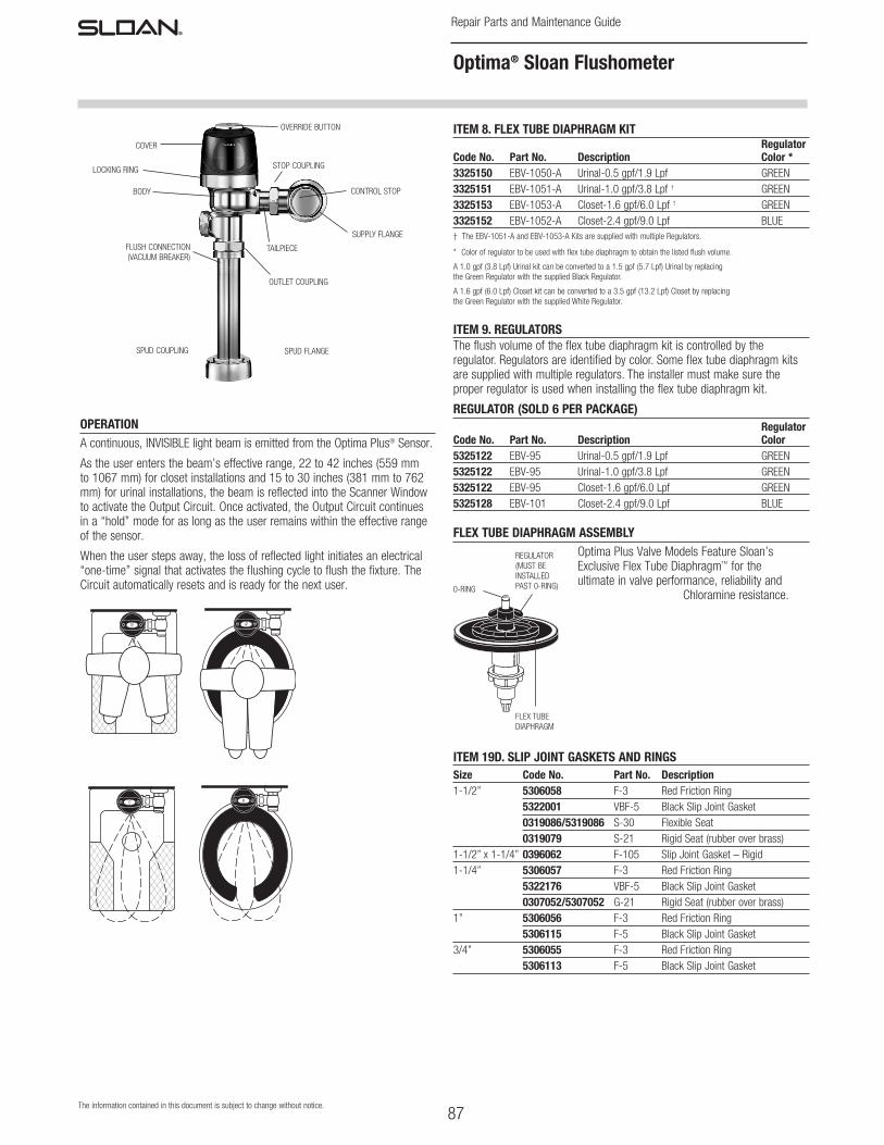
OPERATIONA continuous, INVISIBLE light beam is emitted from the Optima Plus® Sensor.
As the user enters the beam’s effective range, 22 to 42 inches (559 mm to 1067 mm) for closet installations and 15 to 30 inches (381 mm to 762 mm) for urinal installations, the beam is reflected into the Scanner Window to activate the Output Circuit. Once activated, the Output Circuit continues in a “hold” mode for as long as the user remains within the effective range of the sensor.
When the user steps away, the loss of reflected light initiates an electrical “one-time” signal that activates the flushing cycle to flush the fixture. The Circuit automatically resets and is ready for the next user.
COVER
BODY
FLUSH CONNECTION (VACUUM BREAKER)
SPUD COUPLING
LOCKING RING STOP COUPLING
CONTROL STOP
SUPPLY FLANGE
TAILPIECE
OUTLET COUPLING
SPUD FLANGE
OVERRIDE BUTTON
0-RING
REGULATOR (MUST BE INSTALLED PAST 0-RING)
FLEX TUBE DIAPHRAGM
ITEM 8. FLEX TUBE DIAPHRAGM KIT Regulator Code No. Part No. Description Color *3325150 EBV-1050-A Urinal-0.5 gpf/1.9 Lpf GREEN3325151 EBV-1051-A Urinal-1.0 gpf/3.8 Lpf † GREEN3325153 EBV-1053-A Closet-1.6 gpf/6.0 Lpf † GREEN3325152 EBV-1052-A Closet-2.4 gpf/9.0 Lpf BLUE† The EBV-1051-A and EBV-1053-A Kits are supplied with multiple Regulators.
* Color of regulator to be used with flex tube diaphragm to obtain the listed flush volume.
A 1.0 gpf (3.8 Lpf) Urinal kit can be converted to a 1.5 gpf (5.7 Lpf) Urinal by replacing the Green Regulator with the supplied Black Regulator.
A 1.6 gpf (6.0 Lpf) Closet kit can be converted to a 3.5 gpf (13.2 Lpf) Closet by replacing the Green Regulator with the supplied White Regulator.
ITEM 9. REGULATORSThe flush volume of the flex tube diaphragm kit is controlled by the regulator. Regulators are identified by color. Some flex tube diaphragm kits are supplied with multiple regulators. The installer must make sure the proper regulator is used when installing the flex tube diaphragm kit.
REGULATOR (SOLD 6 PER PACKAGE) Regulator Code No. Part No. Description Color5325122 EBV-95 Urinal-0.5 gpf/1.9 Lpf GREEN5325122 EBV-95 Urinal-1.0 gpf/3.8 Lpf GREEN5325122 EBV-95 Closet-1.6 gpf/6.0 Lpf GREEN5325128 EBV-101 Closet-2.4 gpf/9.0 Lpf BLUE
FLEX TUBE DIAPHRAGM ASSEMBLYOptima Plus Valve Models Feature Sloan’s Exclusive Flex Tube Diaphragm™ for the ultimate in valve performance, reliability and
Chloramine resistance.
ITEM 19D. SLIP JOINT GASKETS AND RINGSSize Code No. Part No. Description1-1/2” 5306058 F-3 Red Friction Ring 5322001 VBF-5 Black Slip Joint Gasket 0319086/5319086 S-30 Flexible Seat 0319079 S-21 Rigid Seat (rubber over brass)1-1/2” x 1-1/4” 0396062 F-105 Slip Joint Gasket – Rigid 1-1/4” 5306057 F-3 Red Friction Ring 5322176 VBF-5 Black Slip Joint Gasket 0307052/5307052 G-21 Rigid Seat (rubber over brass)1” 5306056 F-3 Red Friction Ring 5306115 F-5 Black Slip Joint Gasket3/4” 5306055 F-3 Red Friction Ring 5306113 F-5 Black Slip Joint Gasket
88
Repair Parts and Maintenance Guide
The information contained in this document is subject to change without notice.
Optima® Sloan Flushometer
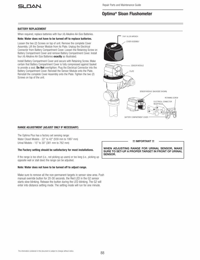
When required, replace batteries with four (4) Alkaline AA-Size Batteries.
Note: Water does not have to be turned off to replace batteries.
Loosen the two (2) Screws on top of unit. Remove the complete Cover Assembly. Lift the Sensor Module from its Plate. Unplug the Electrical Connector from Battery Compartment Cover. Loosen the Retaining Screw on Battery Compartment Cover and remove Battery Compartment Cover. Install four (4) Alkaline AA-Size Batteries exactly as illustrated.
Install Battery Compartment Cover and secure with Retaining Screw. Make certain that Battery Compartment Cover is fully compressed against Gasket to provide a seal; Do Not overtighten. Plug the Electrical Connector into the Battery Compartment Cover. Reinstall the Sensor Module onto the Plate. Reinstall the complete Cover Assembly onto the Plate. Tighten the two (2) Screws on top of the unit.
7/64” ALLEN WRENCH
COVER ASSEMBLY
PLATE
SENSOR MODULE
SENSOR MODULE (BACKSIDE SHOWN)
BATTERY COMPARTMENT COVER
ELECTRICAL CONNECTOR RECEPTACLE
RETAINING SCREW
RANGE ADJUSTMENT (ADJUST ONLY IF NECESSARY)
BATTERY REPLACEMENT
The Optima Plus has a factory set sensing range:Water Closet Models - 22” to 42” (559 mm to 1067 mm)Urinal Models - 15” to 30” (381 mm to 762 mm)
The Factory setting should be satisfactory for most installations.
If the range is too short (i.e., not picking up users) or too long (i.e., picking up opposite wall or stall door) the range can be adjusted.
Note: Water does not have to be turned off to adjust range.
Make sure to remove all the non-permanent targets in sensor view area. Push manual override button for 20-30 seconds. the Red LED in the G2 sensor starts slow blinking. Release the button during the LED blinking. The G2 will enter into distance setting mode. The setting mode will run for one minute.
WHEN ADJUSTING RANGE FOR URINAL SENSOR, MAKE SURE TO SET-UP A PROPER TARGET IN FRONT OF URINAL SENSOR.
!!! IMPORTANT !!!
89
Repair Parts and Maintenance Guide
The information contained in this document is subject to change without notice.
Optima® Sloan Flushometer
IMPORTANT: This product contains mechanical and/or electrical components that are subject to normal wear. These components should be checked on a regular basis and replaced as needed to maintain the valve’s performance.
Never open Control Stop to where the flow from the valve exceeds the flow capability of the fixture. In the event of a valve failure, the fixture must be able to accommodate a continuous flow from the valve.
ATTENTION INSTALLERS: With the exception of the control stop inlet, DO NOT USE pipe sealant or plumbing grease on any valve component or coupling! To protect the chrome or special finish of Sloan flushometers, DO NOT USE toothed tools to install or service these valves. Use our A-50 Super-Wrench™ or other smooth-jawed wrench to secure couplings. Regulations for low consumption fixtures (1.6 gpf/6.0 Lpf closets and 1.0 gpf/3.8 Lpf urinals) prohibit use of higher flush volumes.
1. Sensor flashes continuously only when user steps within range.A. Unit in Start-Up mode; no problem. This feature is active for the first
ten (10) minutes of operation.
2. Valve does not flush; sensor not picking up user.A. Range too short; increase the range.
3. Valve does not flush; sensor picking up opposite wall or surface, or only flushes when someone walks by. Red light flashes continuously for first 10 minutes even with no one in front of the sensor.A. Range too long; shorten range.
4. Valve does not flush even after adjustment.A. Range Adjustment Potentiometer set at full “max” or full “min” setting.
Readjust Potentiometer away from full “max” or “min” setting.
B. Batteries completely used up; replace batteries.
C. Problem with Electronic Sensor Module; replace Electronic Sensor Module.
5. Unit flashes four (4) quick times when user steps within range.A. Batteries low; replace batteries.
6. Valve does not shut off.A. Bypass Orifice in Diaphragm is clogged with dirt or debris, or Bypass
is clogged by an invisible gelatinous film due to “over-treated” water. Remove Flex Tube Diaphragm and wash under running water.
Note: Size of orifice in the by-pass is of utmost importance for the proper metering of water by the valve. DO NOT ENLARGE OR DAMAGE THIS ORIFICE. Replace flex tube diaphragm if cleaning does not correct the problem.
B. Dirt or debris fouling Stem or Flex Tube Diaphragm. Remove Flex Tube Diaphragm and wash under running water.
C. O-ring on Stem of Flex Tube Diaphragm is damaged or worn. Replace O-ring if necessary.
D. Problem with Electronic Sensor Module; replace Sensor Module.
7. Not enough water to fixture.A. Wrong Flush Volume Regulator installed in Flex Tube Diaphragm Kit.
Install the correct Regulator (see Step 6 of these instructions).
B. Wrong Optima Plus® Diaphragm kit installed; i.e., 1 gpf. urinal installed on 3.5 gal. closet fixture. Replace with proper Optima Plus diaphragm kit.
C. Enlarged Bypass in Diaphragm. Replace Flex Tube Diaphragm.
D. Control Stop not adjusted properly. Readjust Control Stop.
E. Inadequate volume or pressure at supply. Increase water pressure or supply (flow) to valve. Consult factory for assistance.
8. Too much water to fixture.A. Wrong Flush Volume Regulator installed in Flex Tube Diaphragm Kit.
Install the correct Regulator (see Step 6 of these instructions).
B. Control Stop not adjusted properly. Readjust Control Stop.
C. Wrong Optima Plus Diaphragm kit installed; i.e., 3.5 gpf. closet installed on 0.5 gal. urinal fixture. Replace with proper Optima Plus Diaphragm kit.
D. Dirt in Diaphragm Bypass. Clean under running water or replace Flex Tube Diaphragm.
CARE AND CLEANING OF CHROME AND SPECIAL FINISHES
DO NOT USE abrasive or chemical cleaners to clean flushometers as they may dull the luster and attack the chrome or special decorative finishes. Use ONLY soap and water, then wipe dry with clean cloth or towel.
While cleaning the bathroom tile, the flushometer should be protected from any splattering of cleaner. Acids and cleaning fluids can discolor or remove chrome plating.
When assistance is required, please contact Sloan Technical Support at: 1-888-SLOAN-14 (1-888-756-2614).
TROUBLESHOOTING AND MAINTAINING THE SLOAN OPTIMA PLUS® FLUSHOMETER