Embed Size (px)
Citation preview
1
OPTIMALST RANGE
www.merriottuk.com www.merriott.ie
2
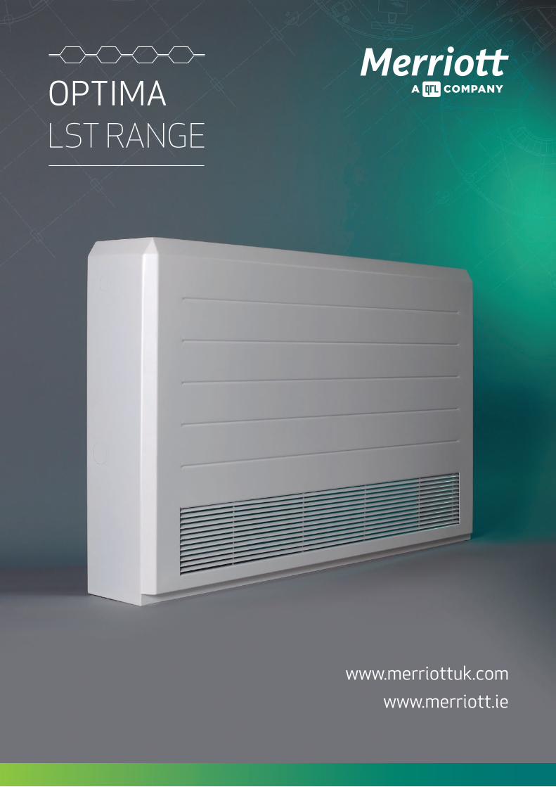
page 0RANGE SUMMARY
page 0-06SPECIFICATIONS
page 0-0OUTPUTS
page 0 - INSTALLATION DETAILS
page - DESIGN INFORMATION
page CERTIFICATIONS
Version 1 - July 2017

3
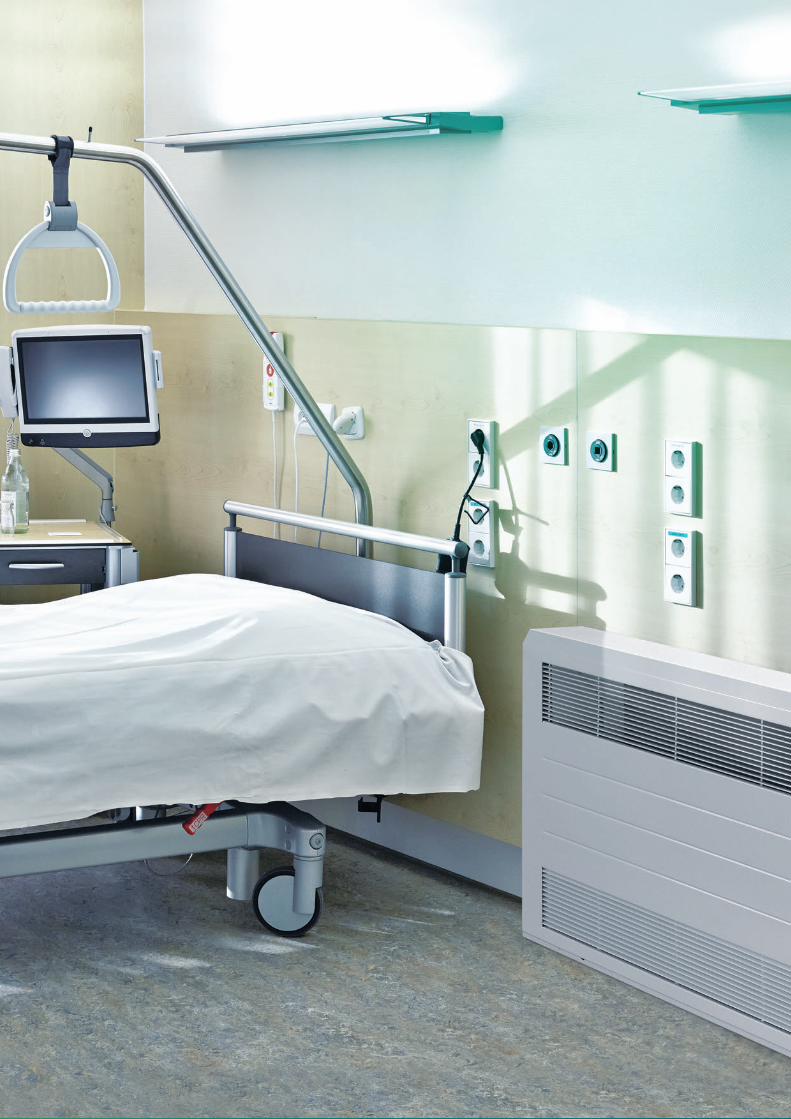
OPTIMARANGEMeeting the market’s demand in terms of low water content and energy savings, the new LST Optima, certified in accordance with BS EN 442, delivers warmth, safety and elegance for end-users and simplicity of installation for contractors.
The Optima Range is ideal for the education, healthcare and residential care sectors.
Floor Standing Wall Mounted
A lOw waTeR cOnTenT, high heaT OuTpuTLST RANGE whIch ISquick & easy TO insTall
CaSing:
Strong single piece profiled casing in 1.6mm steel
3 heights: 500mm, 650mm, 800mm
8 lengths: 650mm, 850mm, 1050mm, 1250mm, 1450mm, 1650mm, 1850mm, 2050mm
3 depths: 120mm, 170mm, 220mm
4 models: wTG (wall Top Grille), wFG (wall Front Grille), FTG (Floor Top Grille), FFG (Floor Front Grille)
Style: Linear front with 3mm deep rib detail for extra strength & durability
eMitter:
Low h2O, high output fin coil heat exchanger
2 height: 100mm, 200mm
8 lengths: 525mm, 725mm, 925mm, 1125mm, 1325mm, 1525mm, 1725mm, 1925mm
3 depths: 100mm, 150mm, 200mm
WtgFtg WFgFFg
4
SPECIFICATIONSeMitter SpeCiFiCation:
Low h2O, high output fi n coil heat exchanger.
Low water content from 0.75 litres per metre.
Non-corrosive 0.2mm aluminium fi ns & 15mm diameter copper tubes.
corrugated aluminium fi ns to maximise convective surface area.
Single pipe reverse fl ow heat exchanger, continuous mass fl ow for optimum output effi ciency.
Same end connections, reversible heat exchanger can be connected left or right with standard valve, TRV or remote sensor.
high, low level and internal tamper proof TRV options available.
Standard connection position 40mm close to the wall for all heat exchangers.
Dual quick-fi t bracket system for emitt er & casing, supplied with bracket spacing bar.
Supplied with ½” BSP directional air vent & blank.
Dirt and dust repellent epoxy polyester powder coat fi nish in matt graphite grey to RAL7024.
working pressure 10 bar, test pressure 13 bar Maximum operating temperature 120 °c.
10 year warranty.
Outputs tested in accordance with BS EN442 independently by BSRIA.
Optima is the result of a pioneering partnership between QRL, the leading manufacturer of high technology radiator solutions in UK and Ireland, and Kampmann, one of the leading manufacturers in the heating, cooling and ventilation sector in Germany and mainland Europe.
QRL and Kampmann collaborated on 12 months of research and development utilising QRL’s £150m, fully automated 1,000,000 square foot production facility in South wales and Kampmann’s state-of-the-art R&D facility in Germany, which includes a certifi ed EN442 Test Booth, and a 125m2 Anechoic chamber.
The resulting Optima LST range benefi ts from the unique water fl ow characteristics of the Kampmann emitt er, and the exceptional air fl ow characteristics of the QRL LST casing. This unrivalled combination delivers the highest effi ciency, low water content LST on the market, with EN 442 outputs and surface temperature certifi cation by BSRIA in the UK.
Critical zone
D/ =50
Complete turbulence
Smooth pipes
Transition zone
Laminar zone
Dividing linebetween zoneto completeturbulence andtransition zone
TurbulentLaminar
20004000
Fric
tion
fact
or ƒ
Reynolds number NR
.10
.08
.06
.04
.03
.02
.01
10³ 10⁴ 10⁵ 10⁶ 10⁷ 10⁸
D/ =500
D/ =20
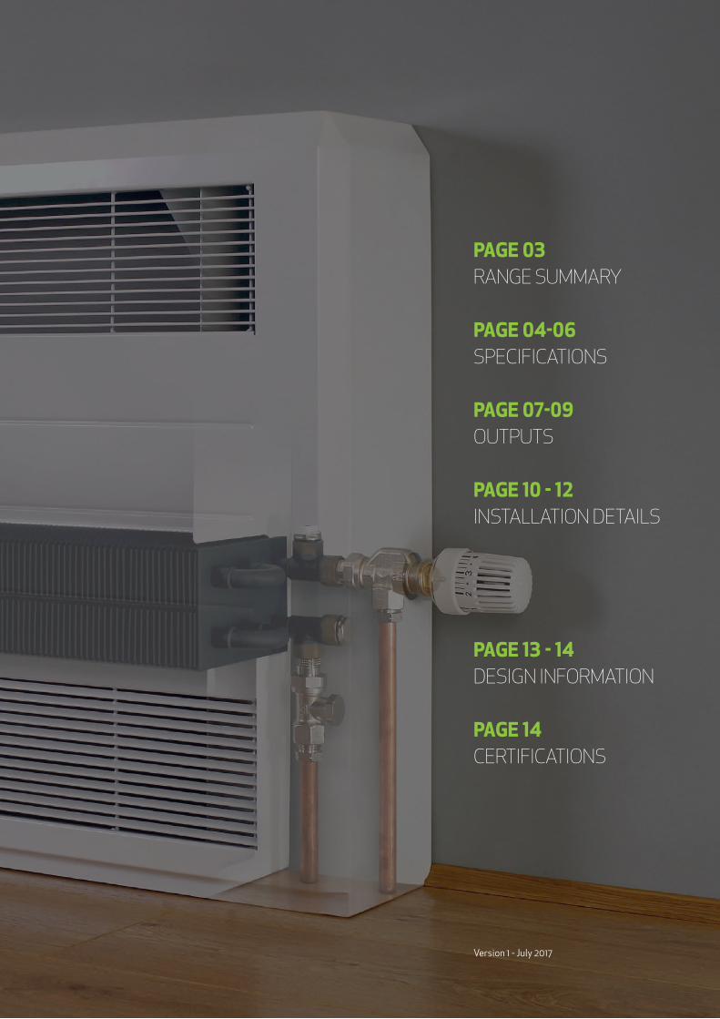
tHe SCienCe beHind eMitter eFFiCienCy
The reason for the higher effi ciency of the Kampmann single pipe fi n coil heat exchanger compared to a multi-pipe manifold in parallel fl ow is due to the eff ect of Turbulent Flow.
heat transfer occurs only at the pipe wall. Laminar Flow develops an insulating blanket around the wall that signifi cantly reduces emitt er heat output. conversely Turbulent Flow due to turbulence has no restriction at the pipe wall therefore maximum heat output is transferred rapidly to the room.
whether fl ow is Turbulent or Laminar is indicated by the Reynolds number for the pipe. For Reynolds numbers below 2,000 fl ow is Laminar, for numbers above 2,000, the fl ow is Turbulent. The higher the number, the more turbulent the fl ow.
Example emitt er comparison:
optima Fin Coil Single pipe emitt er
100mm high x 150mm deep
reynolds number, 5,200 (turbulent Flow)
typical parallel Flow(with manifold) emitt er
100mm high x 150mm deep
reynolds number, 1,750 (laminar Flow)
(Diagram highlighting how Reynold numbers aff ect whether fl ow is laminar or turbulent)
}in partnerSHip WitH
5
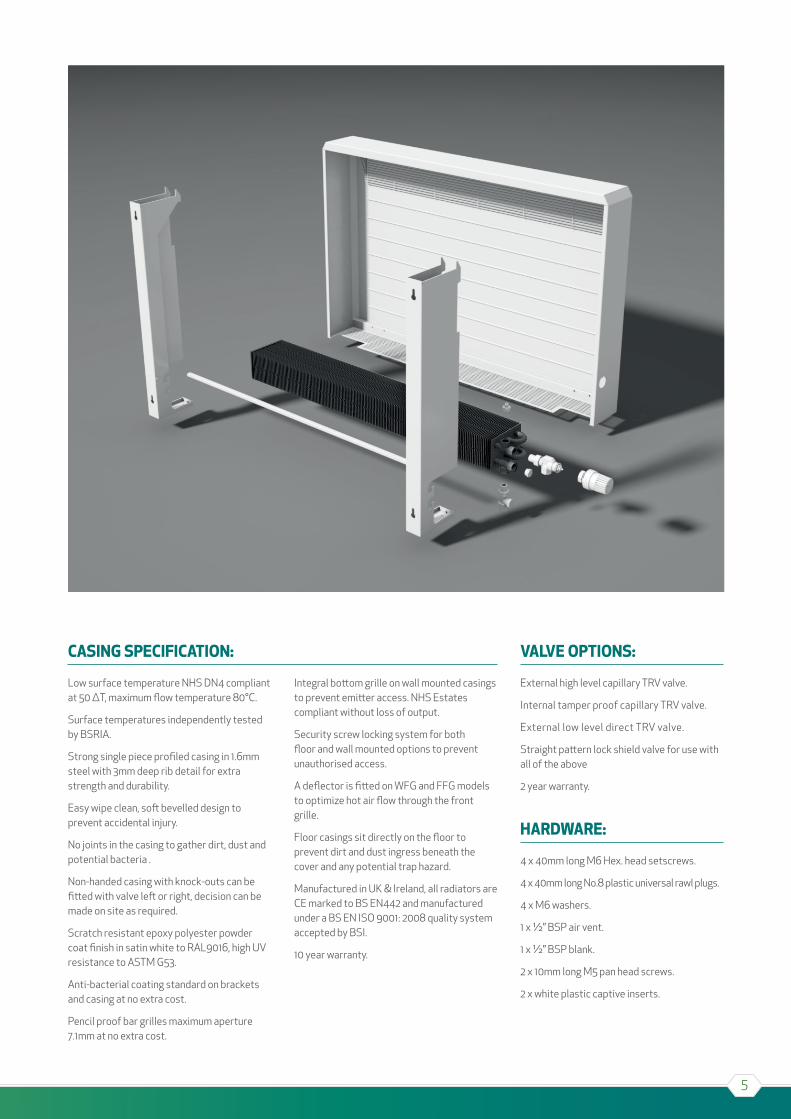
CaSing SpeCiFiCation:
Low surface temperature NhS DN4 compliant at 50 ∆T, maximum flow temperature 80°c.
Surface temperatures independently tested by BSRIA.
Strong single piece profiled casing in 1.6mm steel with 3mm deep rib detail for extra strength and durability.
Easy wipe clean, soft bevelled design to prevent accidental injury.
No joints in the casing to gather dirt, dust and potential bacteria .
Non-handed casing with knock-outs can be fitted with valve left or right, decision can be made on site as required.
Scratch resistant epoxy polyester powder coat finish in satin white to RAL9016, high UV resistance to ASTM G53.
Anti-bacterial coating standard on brackets and casing at no extra cost.
Pencil proof bar grilles maximum aperture 7.1mm at no extra cost.
Integral bottom grille on wall mounted casings to prevent emitter access. NhS Estates compliant without loss of output.
Security screw locking system for both floor and wall mounted options to prevent unauthorised access.
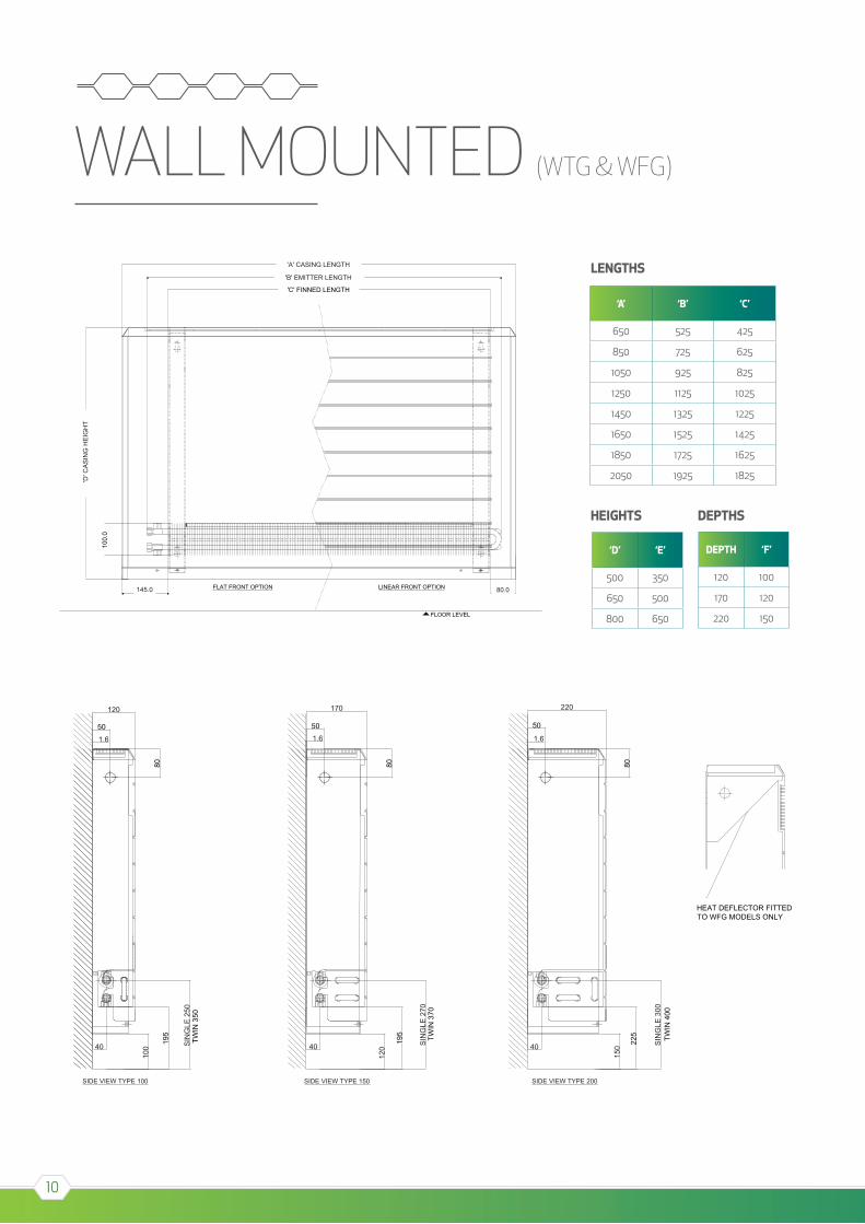
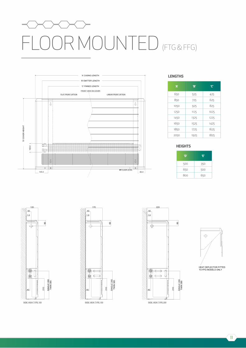
A deflector is fitted on wFG and FFG models to optimize hot air flow through the front grille.
Floor casings sit directly on the floor to prevent dirt and dust ingress beneath the cover and any potential trap hazard.
Manufactured in UK & Ireland, all radiators are cE marked to BS EN442 and manufactured under a BS EN ISO 9001: 2008 quality system accepted by BSI.
10 year warranty.
ValVe optionS:
External high level capillary TRV valve.
Internal tamper proof capillary TRV valve.
External low level direct TRV valve.
Straight pattern lock shield valve for use with all of the above
2 year warranty.
HardWare:
4 x 40mm long M6 hex. head setscrews.
4 x 40mm long No.8 plastic universal rawl plugs.
4 x M6 washers.
1 x ½” BSP air vent.
1 x ½” BSP blank.
2 x 10mm long M5 pan head screws.
2 x white plastic captive inserts.

6
paCkaging:
Optima is supplied as a single pack; the casing is packaged in a heavy-duty cardboard box with lid and within the box the emitter is wrapped separately in a cardboard sleeve and plastic banded. The brackets are nested together and wrapped separately and securely in protective bubble wrap. The box is also supplied with additional inner cardboard corner pads and polystyrene stack supports to ensure complete protection for the product whilst in transit.
inStallation:
For indirect or closed circuits only, with a maximum working temperature of 80°c.
The system should be designed in accordance with the British Standard code of Practice for water Based heating Systems in Buildings BS EN 12828+A1:2014 and BS EN 12831:2003.
The installation of the system and commissioning of the system should comply with BS EN 14336:2004.
On completion of the installation, BSRIA (water Treatment for closed heating & cooling Systems - BG 50/2013) & IcOM recommend flushing, chemical cleaning, the use of appropriate inhibitors, and the testing of water quality in commercial heating systems.
Merriott strongly recommend the use of corrosion inhibitor for all applications. Failure to observe these standards may invalidate the manufacturer’s warranty.
optionS aVailable on requeSt:
Style: Flat front (without rib detail).
Anti-ligature grilles to BS EN 60529:1992+A2:2013, IPX3 rated (maximum aperture 2.5mm diameter). May affect output when used.
TRV valves with mass flow pre-setting.
tHerMoStatiC radiator ValVeS:
external HigH leVel Capillary
consists of a 15mm angled valve body fitted to the emitter inside the casing and linked by capillary tube to an external TRV head. The head is secured by simply tightening the unit thru the pre-formed knock out at the top side of the casing. This can be positioned left or right. The specially designed grip on the TRV head facilitates the use by people with limited hand mobility and can be pre-set to the desired temperature required.
internal taMper prooF Capillary
consists of a 15mm angled valve body and TRV head fitted to the emitter inside the casing with an external remote capillary sensor attached to the wall or underside of the casing below the emitter. This can be positioned left or right. The TRV head can be pre-set to the desired temperature and is tamper proof, only accessible to authorised personal by unlocking the casing.
external loW leVel direCt
consists of a simple 15mm axial valve body fitted to the emitter that protrudes thru a pre-formed knock out at the bottom side of the casing. This can be positioned left or right. The TRV head fits directly on the valve outside the casing. The TRV head can be pre-set to the desired temperature required.
7
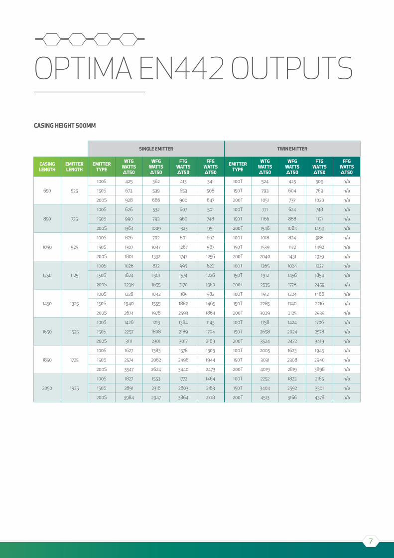
OPTIMA EN442 OUTPUTS
Single eMitter tWin eMitter
CaSing lengtH
eMitter lengtH
eMitter type
Wtg WattS ∆t50
WFg WattS ∆t50
Ftg WattS ∆t50
FFg WattS ∆t50
eMitter type
Wtg WattS ∆t50
WFg WattS ∆t50
Ftg WattS ∆t50
FFg WattS ∆t50
650 525
100S 425 362 413 341 100T 524 425 509 n/a
150S 673 539 653 508 150T 793 604 769 n/a
200S 928 686 900 647 200T 1051 737 1020 n/a
850 725
100S 626 532 607 501 100T 771 624 748 n/a
150S 990 793 960 748 150T 1166 888 1131 n/a
200S 1364 1009 1323 951 200T 1546 1084 1499 n/a
1050 925
100S 826 702 801 662 100T 1018 824 988 n/a
150S 1307 1047 1267 987 150T 1539 1172 1492 n/a
200S 1801 1332 1747 1256 200T 2040 1431 1979 n/a
1250 1125
100S 1026 872 995 822 100T 1265 1024 1227 n/a
150S 1624 1301 1574 1226 150T 1912 1456 1854 n/a
200S 2238 1655 2170 1560 200T 2535 1778 2459 n/a
1450 1325
100S 1226 1042 1189 982 100T 1512 1224 1466 n/a
150S 1940 1555 1882 1465 150T 2285 1740 2216 n/a
200S 2674 1978 2593 1864 200T 3029 2125 2939 n/a
1650 1525
100S 1426 1213 1384 1143 100T 1758 1424 1706 n/a
150S 2257 1808 2189 1704 150T 2658 2024 2578 n/a
200S 3111 2301 3017 2169 200T 3524 2472 3419 n/a
1850 1725
100S 1627 1383 1578 1303 100T 2005 1623 1945 n/a
150S 2574 2062 2496 1944 150T 3031 2308 2940 n/a
200S 3547 2624 3440 2473 200T 4019 2819 3898 n/a
2050 1925
100S 1827 1553 1772 1464 100T 2252 1823 2185 n/a
150S 2891 2316 2803 2183 150T 3404 2592 3301 n/a
200S 3984 2947 3864 2778 200T 4513 3166 4378 n/a
CaSing HeigHt 500MM
8
Single eMitter tWin eMitter
CaSing lengtH
eMitter lengtH
eMitter type
Wtg WattS ∆t50
WFg WattS ∆t50
Ftg WattS ∆t50
FFg WattS ∆t50
eMitter type
Wtg WattS ∆t50
WFg WattS ∆t50
Ftg WattS ∆t50
FFg WattS ∆t50
650 525
100S 457 418 453 394 100T 576 491 558 463
150S 739 624 716 588 150T 870 698 844 657
200S 1018 794 987 748 200T 1154 853 1119 804
850 725
100S 687 615 666 580 100T 848 723 821 681
150S 1087 918 1053 864 150T 1280 1027 1241 967
200S 1498 1168 1452 1100 200T 1697 1254 1645 1182
1050 925
100S 907 812 879 766 100T 1119 954 1084 899
150S 1435 1211 1390 1141 150T 1690 1355 1638 1276
200S 1977 1541 1916 1452 200T 2240 1656 2171 1560
1250 1125
100S 1126 1009 1092 951 100T 1390 1185 1347 1117
150S 1782 1505 1727 1418 150T 2099 1684 2035 1586
200S 2456 1915 2381 1804 200T 2783 2057 2698 1938
1450 1325
100S 1346 1205 1305 1137 100T 1661 1416 1610 1335
150S 2130 1798 2064 1694 150T 2509 2013 2432 1895
200S 2935 2288 2846 2156 200T 3326 2459 3224 2316
1650 1525
100S 1566 1402 1518 1322 100T 1932 1647 1872 1553
150S 2478 2092 2401 1971 150T 2918 2341 2829 2204
200S 3414 2662 3310 2508 200T 3869 2860 3751 2695
1850 1725
100S 1786 1599 1731 1508 100T 2204 1879 2135 1771
150S 2826 2386 2738 2247 150T 3328 2670 3226 2514
200S 3894 3036 3775 2860 200T 4412 3261 4277 3073
2050 1925
100S 2006 1796 1944 1694 100T 2475 2110 2398 1989
150S 3174 2679 3075 2524 150T 3738 2998 3623 2823
200S 4373 3409 4239 3212 200T 4955 3663 4803 3451
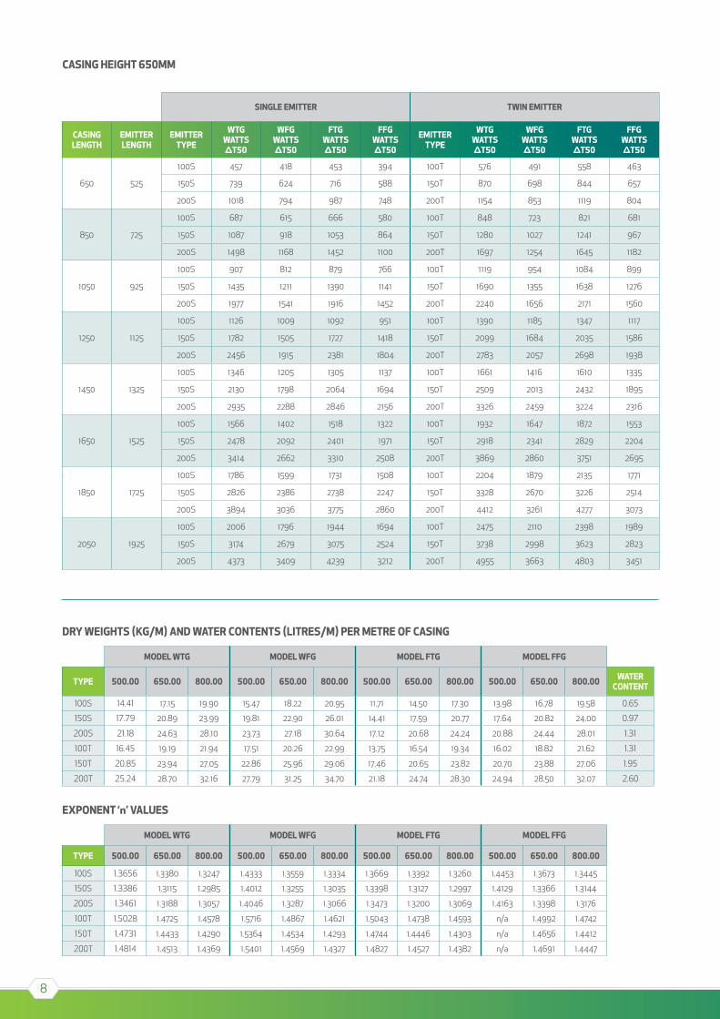
CaSing HeigHt 650MM
dry WeigHtS (kg/M) and Water ContentS (litreS/M) per Metre oF CaSing
exponent ‘n’ ValueS
Model Wtg Model WFg Model Ftg Model FFg
type 500.00 650.00 800.00 500.00 650.00 800.00 500.00 650.00 800.00 500.00 650.00 800.00 Water Content
100S 14.41 17.15 19.90 15.47 18.22 20.95 11.71 14.50 17.30 13.98 16.78 19.58 0.65
150S 17.79 20.89 23.99 19.81 22.90 26.01 14.41 17.59 20.77 17.64 20.82 24.00 0.97
200S 21.18 24.63 28.10 23.73 27.18 30.64 17.12 20.68 24.24 20.88 24.44 28.01 1.31
100T 16.45 19.19 21.94 17.51 20.26 22.99 13.75 16.54 19.34 16.02 18.82 21.62 1.31
150T 20.85 23.94 27.05 22.86 25.96 29.06 17.46 20.65 23.82 20.70 23.88 27.06 1.95
200T 25.24 28.70 32.16 27.79 31.25 34.70 21.18 24.74 28.30 24.94 28.50 32.07 2.60
Model Wtg Model WFg Model Ftg Model FFg
type 500.00 650.00 800.00 500.00 650.00 800.00 500.00 650.00 800.00 500.00 650.00 800.00
100S 1.3656 1.3380 1.3247 1.4333 1.3559 1.3334 1.3669 1.3392 1.3260 1.4453 1.3673 1.3445
150S 1.3386 1.3115 1.2985 1.4012 1.3255 1.3035 1.3398 1.3127 1.2997 1.4129 1.3366 1.3144
200S 1.3461 1.3188 1.3057 1.4046 1.3287 1.3066 1.3473 1.3200 1.3069 1.4163 1.3398 1.3176
100T 1.5028 1.4725 1.4578 1.5716 1.4867 1.4621 1.5043 1.4738 1.4593 n/a 1.4992 1.4742
150T 1.4731 1.4433 1.4290 1.5364 1.4534 1.4293 1.4744 1.4446 1.4303 n/a 1.4656 1.4412
200T 1.4814 1.4513 1.4369 1.5401 1.4569 1.4327 1.4827 1.4527 1.4382 n/a 1.4691 1.4447
9
degreeS Centigrade
5˚c 0.0501 30˚c 0.5148 55˚c 1.1319
10˚c 0.1234 35˚c 0.6290 60˚c 1.2675
15˚c 0.2091 40˚c 0.7482 65˚c 1.4065
20˚c 0.3039 45˚c 0.8720 70˚c 1.5487
25˚c 0.4061 50˚c 1.0000 75˚c 1.6940
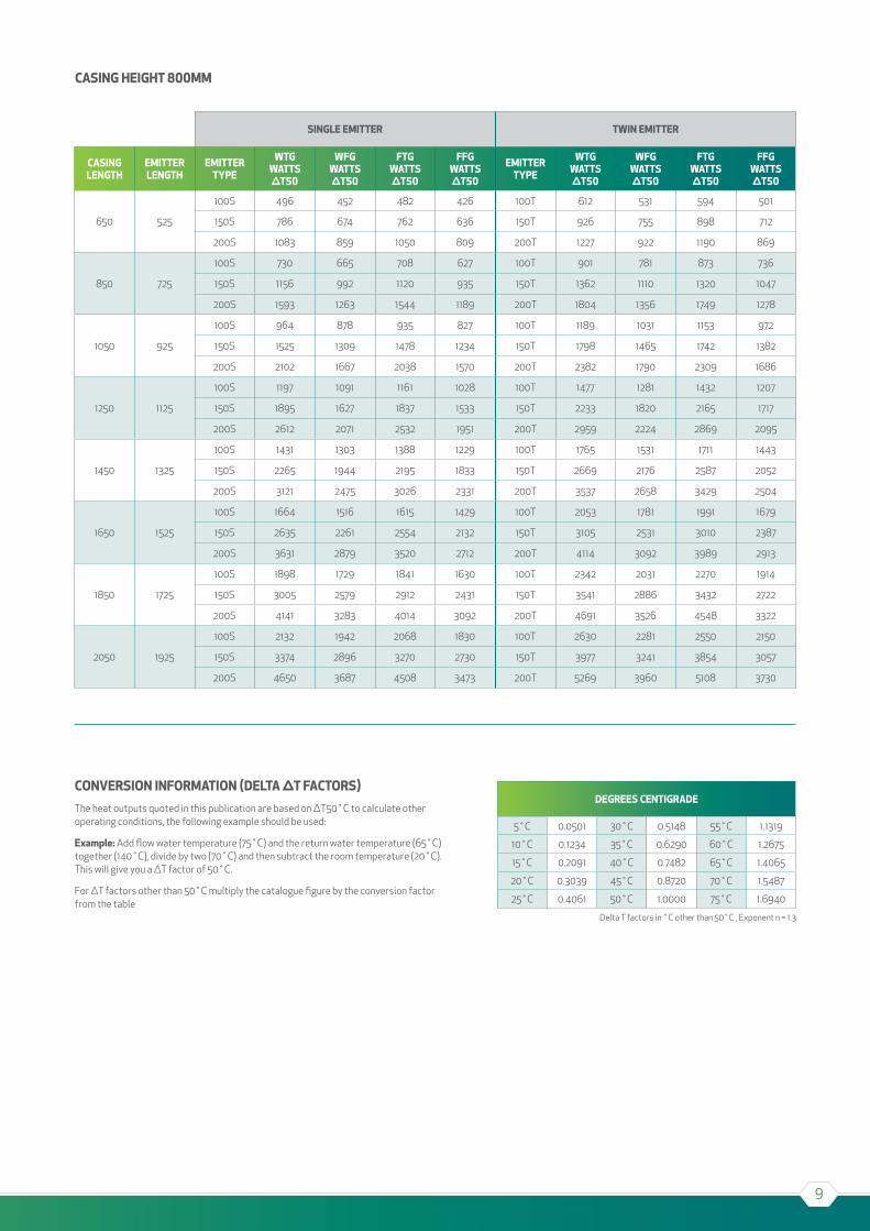
Delta T factors in ˚c other than 50˚c , Exponent n = 1.3
ConVerSion inForMation (delta ∆t FaCtorS)The heat outputs quoted in this publication are based on ∆T50˚c to calculate other operating conditions, the following example should be used:
example: Add flow water temperature (75˚c) and the return water temperature (65˚c) together (140˚c), divide by two (70˚c) and then subtract the room temperature (20˚c). This will give you a ∆T factor of 50˚c.
For ∆T factors other than 50˚c multiply the catalogue figure by the conversion factor from the table
Single eMitter tWin eMitter
CaSing lengtH
eMitter lengtH
eMitter type
Wtg WattS ∆t50
WFg WattS ∆t50
Ftg WattS ∆t50
FFg WattS ∆t50
eMitter type
Wtg WattS ∆t50
WFg WattS ∆t50
Ftg WattS ∆t50
FFg WattS ∆t50
650 525
100S 496 452 482 426 100T 612 531 594 501
150S 786 674 762 636 150T 926 755 898 712
200S 1083 859 1050 809 200T 1227 922 1190 869
850 725
100S 730 665 708 627 100T 901 781 873 736
150S 1156 992 1120 935 150T 1362 1110 1320 1047
200S 1593 1263 1544 1189 200T 1804 1356 1749 1278
1050 925
100S 964 878 935 827 100T 1189 1031 1153 972
150S 1525 1309 1478 1234 150T 1798 1465 1742 1382
200S 2102 1667 2038 1570 200T 2382 1790 2309 1686
1250 1125
100S 1197 1091 1161 1028 100T 1477 1281 1432 1207
150S 1895 1627 1837 1533 150T 2233 1820 2165 1717
200S 2612 2071 2532 1951 200T 2959 2224 2869 2095
1450 1325
100S 1431 1303 1388 1229 100T 1765 1531 1711 1443
150S 2265 1944 2195 1833 150T 2669 2176 2587 2052
200S 3121 2475 3026 2331 200T 3537 2658 3429 2504
1650 1525
100S 1664 1516 1615 1429 100T 2053 1781 1991 1679
150S 2635 2261 2554 2132 150T 3105 2531 3010 2387
200S 3631 2879 3520 2712 200T 4114 3092 3989 2913
1850 1725
100S 1898 1729 1841 1630 100T 2342 2031 2270 1914
150S 3005 2579 2912 2431 150T 3541 2886 3432 2722
200S 4141 3283 4014 3092 200T 4691 3526 4548 3322
2050 1925
100S 2132 1942 2068 1830 100T 2630 2281 2550 2150
150S 3374 2896 3270 2730 150T 3977 3241 3854 3057
200S 4650 3687 4508 3473 200T 5269 3960 5108 3730
CaSing HeigHt 800MM
10
‘A’ ‘B’ ‘C’
650 525 425
850 725 625
1050 925 825
1250 1125 1025
1450 1325 1225
1650 1525 1425
1850 1725 1625
2050 1925 1825
‘D’ ‘E’
500 350
650 500
800 650
DEPTH ‘F’
120 100
170 120
220 150
WALL MOUNTED (WTG & WFG)
LENGTHS
HEIGHTS DEPTHS
'A' CASING LENGTH
'B' EMITTER LENGTH
'D' C
AS
ING
HE
IGH
T
LINEAR FRONT OPTIONFLAT FRONT OPTION
100.
0
'C' FINNED LENGTH
FLOOR LEVEL
145.0 80.0
11
‘A’ ‘B’ ‘C’
650 525 425
850 725 625
1050 925 825
1250 1125 1025
1450 1325 1225
1650 1525 1425
1850 1725 1625
2050 1925 1825
‘D’ ‘E’
500 350
650 500
800 650
FLOOR MOUNTED (FTG & FFG)
LENGTHS
HEIGHTS
LINEAR FRONT OPTIONFLAT FRONT OPTION
FLOOR LEVEL
FRONT VIEW ON COVER
'A' CASING LENGTH
'B' EMITTER LENGTH
'C' FINNED LENGTH
'D' C
OV
ER
HE
IGH
T
100.
0
145.0 80.0
12
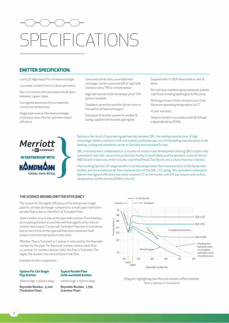
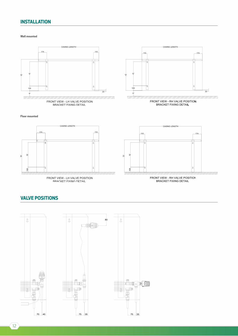
INSTALLATION
VALVE POSITIONS
NL
Wall mounted
Floor mounted
13
5 4 3 2 140003000
2000
1000
500400300
200
100
504030
20
10
543
2
1
Water flow rate m [l/h]
10 20 50 100 200 500 1000
Wat
er p
ress
ure
r per
casi
ng le
ngth
l [Pa
/m]
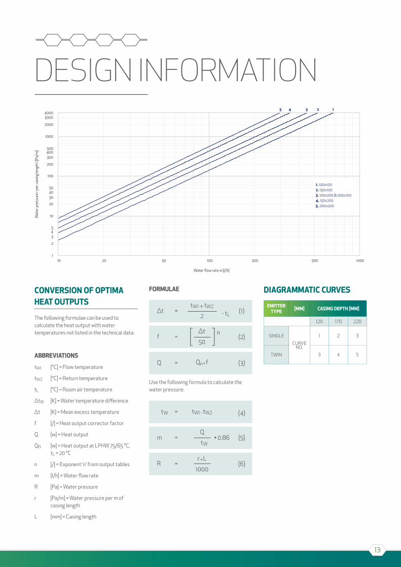
1. 100x1002. 150x1003. 100x200 & 200x1004. 150x2005. 200x200
DESIGN INFORMATION
ConVerSion oF optiMa Heat outputS
The following formulae can be used to calculate the heat output with water temperatures not listed in the technical data:
abbreViationS
tw1 [°c] = Flow temperature
tw2 [°c] = Return temperature
tL [°c] = Room air temperature
∆tw [K] = water temperature difference
∆t [K] = Mean excess temperature
f [/] = heat output corrector factor
Q [w] = heat output
Qn [w] = heat output at LPhw 75/65 °c, tL = 20 °c
n [/] = Exponent ‘n’ from output tables
m [l/h] = water flow rate
R [Pa] = water pressure
r [Pa/m] = water pressure per m of casing length
L [mm] = casing length
ForMulae
Use the following formula to calculate the water pressure:
diagraMMatiC CurVeS
eMittertype [MM] CaSing deptH [MM]
120 170 220
SINGLE
cURVE NO.
1 2 3
TwIN 3 4 5
tw =
Q
r • L
1000
(4)
m = • 0.86 (5)tw
R = (6)
14
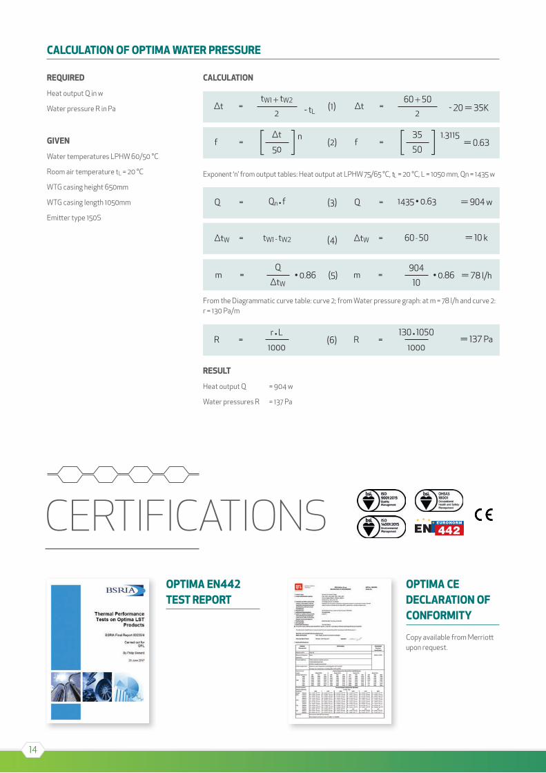
CERTIFICATIONS
REQUIRED
Heat output Q in w
Water pressure R in Pa
GIVEN
Water temperatures LPHW 60/50 °C
Room air temperature tL = 20 °C
WTG casing height 650mm
WTG casing length 1050mm
Emi� er type 150S
CALCULATION
Exponent ‘n’ from output tables: Heat output at LPHW 75/65 °C, tL = 20 °C, L = 1050 mm, Qn = 1435 w
From the Diagrammatic curve table: curve 2; from Water pressure graph: at m = 78 l/h and curve 2: r = 130 Pa/m
RESULT
Heat output Q = 904 w
Water pressures R = 137 Pa
CALCULATION OF OPTIMA WATER PRESSURE
OPTIMA CE DECLARATION OF CONFORMITY
Copy available from Merrio� upon request.
OPTIMA EN442 TEST REPORT
15

16
Merriott uk(MANUFAcTURING FAcILITY)
QRL Radiator Group, Imperial ParkNewport, NP10 8FS
Tel: +44 (0) 1633 657 000
Fax: +44 (0) 1633 681 864
Merriott ireland
QRL Radiator Group, 11 Gortahurk Road, Tonymore, Derrylin,
co. Fermanagh, BT92 9DD
nortHern ireland
Tel: 0800 389 9980
Fax: 0286 774 2998
sales@merriott uk.com
republiC oF ireland
Tel: 1800 882 332
Fax: 0486 774 2998
sales@merriott .ie
www.merriott uk.com / www.merriott .ie
Follow us on @merriott uk and