Embed Size (px)
Citation preview
33RD INTERNATIONAL COSMIC RAY CONFERENCE, RIO DE JANEIRO 2013THE ASTROPARTICLE PHYSICS CONFERENCE
Optics development of ultra high energy cosmic rays detector KLYPVE on-board ISSS.A. SHARAKIN1, V. BATSHEV2, B.A. KHRENOV1, P.A. KLIMOV1 , I.V. YASHIN1
1 Lomonosov Moscow State University, Skobeltsyn Institute of Nuclear Physics, Moscow, Russia2 Bauman Moscow State Technical University, Moscow, Russia
Abstract: High energy cosmic rays detection from low earth orbit (for example TUS and JEM-EUSO projects)requires development of special optic systems (OS). Characteristics of these OS largely differ from astronomicalcosmic telescope ones: wider field of view, relatively lower angular resolution, a few numbers of optic components.New Russian project on board of International Space Station - KLYPVE - aims to spectral measurements oftransient luminous events as well. In this paper we offer one (generalized Davies-Cotton systems) and twocomponents OS allowing to realize such multipurpose research
Keywords: Optics, KLYPVE, space detector, UHECR.
1 IntroductionUltra high energy cosmic ray (UHECR1) study by regis-tration of fluorescence signal from Extensive Air Shower(EAS) has both the own history - fluorescence detectorsFly’s Eye and HiRes, and the present - ones at AUGERand Telescope Array. All these detectors operate at groundlooking up to the atmosphere (really looking aside at eleva-tion angles 0-30◦). The future of this method is associatedwith the imposition of the instruments into the earth orbit:for UHECR physics the most important parameter of thefluorescence detector is area of the atmosphere covered byobservation. It determines statistics of the highest energyevents and today it is too small for obtaining final results onorigin of UHECR. Larger area of the atmosphere coveredby fluorescence detectors could be achieved by detectorslooking down to the atmosphere from satellite board. Inthis case fluorescence detector operates as a Space CosmicRays Telescope (SCRT) covering by one instrument area oftens thousands of square km in the atmosphere from orbitheights 400–500 km. Nowadays the original idea of Linsley[1] has being developed into projects of cosmic rays tele-scopes for International Space Station (ISS): JEM-EUSO- to be installed on the Japanese experimental module [2]and KLYPVE - on the Russian ISS segment.
SCRT is not the “astronomical” type of telescope al-though the main telescope conception remains valid: it isused for observation of remote weak signal. Object of ob-servation is moving disc of charged particles generated byUHECR in the Earth atmosphere: the charged particles ion-ize and excite molecules of atmosphere which radiate “fluo-rescence” in tens of nanoseconds in near UV band of wave-lengths (300–400 nm). Typical size of EAS disc are: trans-verse diameter ∼ 1 km, thickness ∼ 0.1 km, EAS length -20–100 km (depending on EAS zenith angle), and the flu-orescence light can be observed from large distance as apoint source moving in the atmosphere with light veloc-ity. So the main components of SCRT - Optic System andPhoto Detector - should have sufficiently high angular andtemporal resolutions.
In UHECR experiment “high” angular resolution isdetermined as accuracy resolving dimensions of source(0.1–1 km) from distance to telescope of 400–500 km, i.e.
accuracy has to be better than 1 mrad (3–4 minutes ofarc). This accuracy is much higher than already achieved inground based fluorescence detectors (∼ 30 minutes of arc)but is very rough to compare with astronomical telescopes(cf. with 0.5 seconds of arc of the Large Synoptic SurveyTelescope). Telescope field of view (FoV) has to cover atleast one full event with length in atmosphere of about50 km (angular length ∼ 0.1 rad ∼ 6◦).
Design of SCRT optics should meet the following re-quirements.
1. Optical systems must be composed of minimal ele-ment number, typically one or two. In this case it iseasier to minimize light losses and to adjust opticalelements and photo receiver in space (automaticallyor manually by astronaut).
2. It should have very large primary concentrator withentrance pupil diameter D = 3–5 m as efficient EASsignal collector (D = 3.6 m for KLYPVE SCRT andD = 1.6 m for its prototype TUS detector, see below).
3. The relative aperture (A = D/ f , f - focal distance)should be near 1 (“fast optics”) because of constrainsto photo receiver size and pixels number.
4. It should have a wide FoV (±5◦ for UHECR thresh-old energies of about 10–20 EeV and ±30◦ - forthe higest energies > 100 EeV) for reasons of highUHECR statistics.
5. The angular resolution could be several minuteswhich corresponds to spatial resolution of about 1–2 km in the atmosphere near the Earth surface.
Optic System of SCRT can be developed in two de-signs: a) telescope-reflector as in KLYPVE project and b)telescope-refractor as in JEM-EUSO.
Reflector optics has advantage of a priori large aperturedue to construction simplicity of one mirror light collectorin space. Large aperture allows to start UHECR measure-ment with lower energy threshold. Narrow FoV of one mir-ror optics is compensated by high statistics of cosmic ray
1. primary particles with energy more than 50 EeV = 5 ·1019 eV
Optics of ultra high energy cosmic rays detector KLYPVE33RD INTERNATIONAL COSMIC RAY CONFERENCE, RIO DE JANEIRO 2013
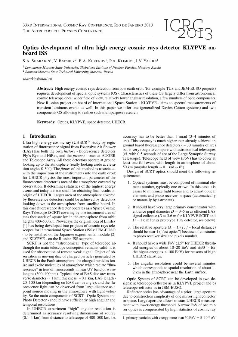
Figure 1: Fresnel mirror of TUS. Right: central segment,one of 6 peripherial segments and its rear surface.
particles at energies close to threshold. On the other handtelescope-refractor optics with less aperture has advantageof a priori wider FoV. In JEM-EUSO wide FoV of ±30◦allows to observe the atmosphere area 105 km2 needed forUHECR research at energies more than 100 EeV.
2 Pathfinder and OS technicalcharacteristics
The first orbital detector of ultra high energy cosmic raysTUS is prepared now in Russia to be launched on boardLomonosov satellite in 2013 [3]. TUS optical system is acomposite (segmented) mirror-concentrator and it consistsof one central and six peripheral segments (figure 1, seealso [4]). Each segment has hexagon shape. Mirror profileis designed as sum of paraboloids of revolution (withcommon axis - the main OS axis), projected to the mountingplane. Thus, it is kind of mirror analog of a Fresnel lens(called below as Fresnel mirror) with different radiusesof curvature of each ring correspondent to ideal on-axisfocusing (without aberrations). Within one ring its heightis fixed and is equal to 1 cm. Fresnel mirror has smalltotal height, which is mostly determined by multilayercarbon plastic structure and presence of bearing surface.Its optical characteristics are similar to ideal paraboloid(within ±4◦ FoV). Side of each segment is equal to 33 cm,an approximate diameter of mirror is D = 160 cm. Focaldistance is f = 150 cm, so the relative aperture is A =D/ f = 1.1.
TUS detector is a pathfinder for UHECR detector be-cause of its narrow FoV and small mirror size. In 2011,D. V. Skobeltsyn Institute of Nuclear Physics of MoscowState University was initiated preliminary design stageof reflector type SCRT for UHECR measurements fromISS board - detector KLYPVE. It will be located on outerside of Russian ISS segement. The main KLYPVE elementis a segmented optical system with large entrance pupil di-ameter. All parts of telescope have to be transported to ISSby Progress-TM vehicle. It means that dimensions of tele-scope parts have to be smaller than 60×120 cm. There arealso limits for focal distance (4 m) and diameter of the mainmirror (3.6 m).
Multicomponent models of optical telescopes were de-veloped before in astronomy, but their manufacturing, de-livery to the orbit and further deployment in the open spacemeet several difficulties. To obtain the large concentratorones have to fabricate separate segments and components,to assemble them into optical system and adjust it with re-spect to the photo receiver in open space automatically orby astronaut. Therefore the design should be limited by oneor two component optical systems.
Technical characteristics of KLYPVE optical system arethe following:
1. OS consists of one primary mirror or from twocomponents (primary mirror and corrective lens).
2. Whole mirror diameter is 360 cm.
3. Overall length of OS is not more than 400 cm.
4. Field of View (half angle) is 7–8 degrees.
5. Image size of point like object should be less thanphoto receiver pixel (15 mm).
6. Focal photo receiver is flat with diameter less than120 cm.
3 Generalized Davies-Cotton systemsGenerally, corrective optics means additional optical ele-ments: corrective mirror or lens. But there is another possi-bility to improve the image quality in a wide range of fieldangles – to use additional degrees of freedom of the mirror-concentrator itself. It is possible if we make mirror grosssurface and its reflective surface not identical to each other.In these terms the gross surface means surface which deter-mines the total shape of concentrator and reflective surfacedetermines the normal direction in each surface point. So,in the ray tracing the points of reflection lie on the gross sur-face, but the ray slewing is given by reflective surface. (Infact, TUS Fresnel-type mirror is an example of such “extradegree of freedom” system where the gross surface is flatand reflective surface is represented by the ring structure ofparaboloids.)
One of the most well-known examples of this approachis a Davies-Cotton System [5]: the gross surface is a spherewith radius f ( f - effective focal distance), but normalof the reflective surface converge at a point, located ata distance 2 f from the pole. Originally Davies-Cottonsystems were developed as solar concentrators, but recentlythey have been widely used in gamma astrophysics - as theatmospheric Cherenkov telescopes (ACT) [6].
Despite the fact that the bearing surface is a sphere,an additional degree of freedom allows the system to beaberration-free on the axis, as in the case of an idealparabolic mirror. Davies-Cotton system are used in ACT(for example, H.E.S.S. [7] and Small Size Telescope CTA[8]) because for larger incidence angles this design outper-forms the parabolic configuration.
Such OS with two degrees of freedom could not be ob-tained in class of smooth continuous surfaces, it means thatmirror surface has to be with breaks. In the ground basedtelescopes with Davies-Cotton system it is achieved by a tes-sellated concentrator. Separate (more often, spherical) mir-rors of relatively small size are mounted on the supportingstructure so, that center of each mirror situated on the grosssurface.
Optics of ultra high energy cosmic rays detector KLYPVE33RD INTERNATIONAL COSMIC RAY CONFERENCE, RIO DE JANEIRO 2013
The tessellated structure appears due to economicalconsiderations and the size of each spherical mirror isselected based on the optimization of two factors: focusingquality and total cost of mosaic. In case of SCRT thenumber of segments and additional work outside ISS shouldbe minimized. Mosaic structure is not suitable for spacework and the most acceptable variant of manufacture isaxisymmetric: the whole mirror or its large parts (segments)are produced in the form of an annular surface, similar toFresnel mirror of TUS. But, unlike the TUS mirror, thegross surface can be arbitrary, and not just flat.
Thus, choosing a rather general parametric class forthe reference surface and profiles of individual rings, it ispossible to select them minimizing the size of image in thefocal plane for entire FoV or for any part of its.
We have performed the study in a class of surfacesof conic sections revolution, two-parameter family: R -surface radius of curvature in pole, δ - conic constant.Entrance pupil (with diameter 360 cm) was divided into11 annular zones, with approximately equal cross sectionarea. The inner edge of each annular zone was beard onthe corresponding point on the gross surface. Reflectivesurfaces of all rings were taken spherical and their radiiof curvatures were optimized. The RMSr for 5◦ incidenceangle was taken as a Merit Function.
The parameters of the optimized solution for the systemwith the relative aperture A = 0.9 (i.e. f = 400 cm) and itsspot size can be found in [9]. Here we only note that theradius of curvature and conic constant of gross surface forthis system are 350 cm and −0.5, similar elliptic telescopedesign was presented early in [10].
This approach allows to expand the FoV up to ±4–5◦.But in this case the difficulties with constructional deptharise. The overall height of such system is about 45 cm,while the same parameter for paraboloid is 20 cm, andfor classical Davies-Cotton scheme - 40 cm. There aredifficulties with these dimensions not only during segmentsmanufacturing stage, but also in a process of their deliveryto the orbit. Moreover, this complicated three dimensionalsystem needs the deployment of special large supportingconstruction.
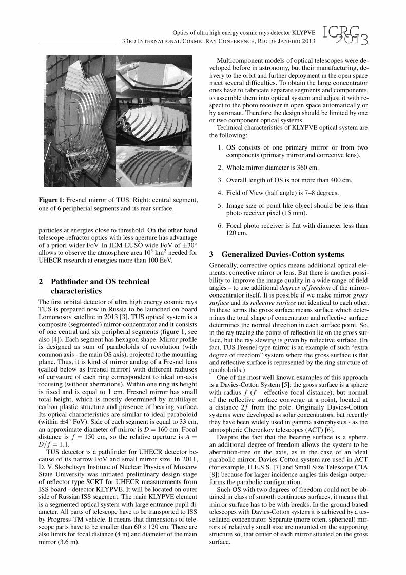
4 Catadioptric systemsAfter modeling the one component system it becomes obvi-ous that it is not suitable for KLYPVE project for two rea-sons: narrow FoV and complicated engineering design. Andat the next stage the two component catadioptric systemswere investigated. In this case besides the primary mirrorthe flat Fresnel lens is placed near photo receiver, figure 2.It is important to emphasize that the lens is attached nearthe front surface of the photo detector, because it allowsto simplify adjustments of separate components of OS, toreduce the requirements for manufacturing precision andsignificantly decrease chromatic aberrations. In this schemelens acts mostly as a light guide rather than a real correctivelens.
Fresnel lenses are the main part of JEM-EUSO opticalsystem. Its baseline version consists of three curved double-sided Fresnel lenses Poly Methyl Methacrylate (PMMA)material (Mitsubishi Rayon Co., Ltd. product). It is usedPMMA material that is more suitable for the near UV(“PMMA-000” grade). It has good UV transmittance (morethan 90% for 15 mm thickness layer at wavelength morethan 320 nm), refractive index about 1.51 and has been used
Figure 2: Catadioptric system: PM - primary mirror, FL -Fresnel lens, PD - focal plane of the Photo Detector. Raytracing through FL is represented at the left (for 0◦, 3◦, 5◦
and 7◦ filed angles).
in space on many occasions. In 2011 The Ohmori Labo-ratory of the RIKEN Advanced Science Institute (Japan)has done the Bread Board Model manufacturing of the cen-tral part of the lenses that has 1.5 m diameter and 10 mmthickness [11]. These lenses have grooves with 1 mm heightand a width varying from 50 to 1 mm. Less dimensions ofgrooves leads to a significant light scattering on the periph-eral parts of the lens.
Therefore, as the initial parameters (requirements) of thelens in this project were selected the following:
Material - PMMA-000 (1.20 density g/cm3).
Thickness - 10 mm.
Grooving height - 1 mm and width - more than 1 mm.
Diameter - no more than 150 cm.
Distance from the lens to photo receiver - no morethan 30 cm.
The last parameter was taken 20 cm and the optimizationstudy was carried out in which the remaining parametersof OS were selected: mirror radius of curvature in the poleRm, and its conic constant δm, the same parameters forprofile of lens, number of grooves and their sizes. Theparameters of one of such optimized OS are shown in thefirst raw of Table 1 (for spherical grooves applied on oneside of flat lens, the second side is smooth). Minimum andmaximum groove’s width (with 1 mm height) equal to 44.7and 1.3 mm. The image size for various angles is given inTable 2.
Rm, cm δm Rf, cm δf # of grv. DL/DPD, cm
807.6 -1 100.0 0 216 124 / 100
608.6 -1 100.0 0 177 113 / 82
Table 1: Primary Mirror and one-side Fresnel Lens charac-teristics: Rm and δm - curvature radius and conic constantof the mirror, Rf and δf - corresponding values for Fresnelfacet shape, overall number of grooves, lens’ diameter anddiameter of focal plane if 7◦ maximum field angle is se-lected.
As we can see this OS model allows expanding the FoVup to 6–7◦, while the image RMSr maintains within one
Optics of ultra high energy cosmic rays detector KLYPVE33RD INTERNATIONAL COSMIC RAY CONFERENCE, RIO DE JANEIRO 2013
photo receiver pixel. The diameter of the obtained lens is124 cm. Primary mirror-concentrator has paroboloid shape(δm = −1) with focal distance fm = Rm/2 = 402.5 cm,which is exceeds the distance between the mirror pole andfocal plane (400 cm).
RMSr RMSx RMSy R70 R90
γ = 0◦ 3.7 2.6 2.6 3.9 4.4
γ = 3◦ 6.0 3.8 4.7 5.6 9.1
γ = 5◦ 9.5 5.1 8.0 8.3 12.6
γ = 7◦ 14.2 6.5 12.6 10.9 21.5
Table 2: Spot radiuses in mm at different field angles (0◦, 3◦,5◦, 7◦) for long-focus sytem with f = 400 cm. In additionto the mean-square radii the radii of the spot with 70% and90% of energy are given in two last columns.
There were considered more general models with anonparabloic primary mirror and/or aspheric profile ofFresnel facet shape. In all these cases it is possible to achieveinsignificant improving of focusing characteristics of OSbut with substantial complication of manufacturing. Theradius of curvature (Rf) decreasing leads to that grooveswidth at the edge becomes less than 1 mm, and it stronglyreduces optic throughput.
SINP MSU have started new stage of KLYPVE designin 2013. And our designers from TSNIIMASH (Korolev)put some new demands on detector construction, and one ofthem was to reduce the overall length of the optical systemdeployable on ISS. The new OS maximal length is 300 cm,so we have to recalculate our models from effective focallength 400 cm to 300 cm. And this is not simple work fromoptical point of view because it corespondes to changing therelative aperture up to A = 1.2. Our prelimenary simulationconcludes that one components system (generalised Davies-Cotton) does not suitable in that case - off-axis aberration(mainly coma which increases as ∼ A2) will be larger thanpixel size of KLYPVE photo detector even at 3◦ field angle.But the catadioptric system is more tunable and similar two-component system can be obtain by optimization procedure.The parameters of that short-focus system and spot sizecharacteristics represented in the second raw of Table 1 andin the Table 3 respectively. The diameters of Fresnel lensand photodetector (if 7◦ maximum field angle is selected)reduce to 113 and 82 cm, minimum groove’s width is1.5 mm.
RMSr RMSx RMSy R70 R90
γ = 0◦ 4.3 3.0 3.0 5.3 5.7
γ = 3◦ 7.9 4.8 6.3 8.7 10.7
γ = 5◦ 12.4 6.8 10.4 12.4 14.3
γ = 7◦ 18.0 8.8 15.7 16.1 25.5
Table 3: Spot radiuses in mm at different field angles (0◦,3◦, 5◦, 7◦) for short-focus sytem with f = 300 cm. Thesame characteristics as in the prevous table are presented.
5 ConclusionsWe considered one and two component optical systemsfor SCRT with 360 cm entrance pupil diameter and 400 cmand 300 cm focal distance (long- and short-focus systems).The main purpose of this study is FoV increasing from 3–4◦ (using just parabolic system) to 7–8◦ which is necessaryfor UHECR measurements with high statistics.
In the case of generalized Davies-Cotton model (onecomponent OS) the concentrator structure is not continuous(it has mosaic or ring structure) but it allows applyingadditional degrees of freedom. The maximum angle atwhich the signal from distant object is focused in a singlephoto receiver pixel (15×15 mm) is 4–5◦ for long-focussystem. But this solution can’t be apply to short-focus case.
To increase a FoV up to 5–6◦ and significantly simplifyprimary mirror construction is possible using two compo-nent system. The spot size (2
√RMSx×RMSy) for field
angle 7◦ is 18 mm, and in the center of FoV - 5 mm. Thecorrective Fresnel lens is used in this case, mounted closeto the focal plane of photo receiver (for the present variantin the 20 cm). The mirror represents the paraboloid of rev-olution with the focal distance of paraboloid is 403.8 cmfor long-focus and 304.4 for short-focus system and rela-tively small overall height (∼ 20 cm). Flat Fresnel lens hasabout 110–120 cm diameter, grooves with 1 mm height andvariable width (1.5–45 mm).
It is important to emphasize that using of large concentra-tor (≈ 10 m2 in KLYPVE project) allow to study not onlyUHECR, but also to provide spectroscopic measurementsof Transient Luminous Events (TLE), see [12]. A numberof photo receiver pixels is planned to replace by a bunch offiber light guides, which transfer focused light to a multi an-ode PMT with 15–20 filters for various spectroscopic chan-nels. These measurements with high temporal and spatialresolution are very important for understanding the natureof TLE and physical processes during the discharge.
So, the KLYPVE is a complex instrument which isdesigned as a wide angle space cosmic rays detector forUHECR measurements and sensitive spectroscope withhigh space-time resolution for TLE study for near-Earthorbit.
References[1] J. Linsley, R. Benson, 17th ICRC Proc. Paris 8 (1981) 145.[2] Andrea Santangelo, 33d ICRC Proc. Rio De Janeiro (2013)
ID0738.[3] A.M. Amelushkin et al., 33d ICRC Proc. Rio De Janeiro
(2013) ID 0339.[4] A. Tkachenko, A. Grinyuk et al., 33d ICRC Proc. Rio De
Janeiro (2013) ID 0423.[5] D.A. Lewis, Exper. Astronomy 1 (1990) 213–236.[6] V. Vassiliev, S. Fegan, and P. Brousseau, Astropart. Phys. 28
(2005) 10–27.[7] K. Bernlohr, O. Carrol, R. Cornils et al., Astropart. Phys.
20(2) (2003) 111–128.[8] The CTA Consortium, Experimental Astronomy 32 (2011)
193–316.[9] S.A. Sharakin, B.A. Khrenov, P.A. Klimov et al., Proc. of
SPIE 8443 (2012) 84433W-1–84433W-11.[10] A. Schliesser, R. Mirzoyan, Astropart. Phys. 24 (2005)
382–390.[11] Y. Hachisu, N. Tone, Y. Uehara, 32d ICRC Proc. Bejin 3
(2011) 179–182.[12] V.S. Morozenko et al., 33d ICRC Proc. Rio De Janeiro
(2013) ID 0519.