Embed Size (px)
Citation preview
Optically driven micropump with a twin spiral microrotor
Shoji Maruo,1,2*
Akira Takaura,1 and Yohei Saito
1
1Department of Mechanical Engineering, Graduate School of Engineering, Yokohama National University, 79-5 Tokiwadai, Hodogaya-ku, Yokohama 240-8501,Japan
2PRESTO, Japan Science and Technology Agency, Sanbancho Building, 3-5, Chiyoda-ku, Tokyo 102-0075, Japan *[email protected]
Abstract: An optically driven micropump that employs viscous drag exerted on a spinning microrotor with left- and right-handed spiral blades on its rotational axis has been developed using two-photon microfabrication. It was demonstrated that the twin spiral microrotor provides a higher rotation speed than a single spiral microrotor. The rotation speed reached 560 rpm at a laser power of 500 mW. The twin spiral microrotor was also applied to a viscous micropump with a U-shaped microchannel. To pump fluid, the twin spiral microrotor located at the corner of the U-shaped microchannel was rotated by focusing a laser beam. The flow field inside the U-shaped microchannel was analyzed using the finite element method (FEM) based on the Navier-Stokes equation to optimize the shape of the microchannel. It was confirmed that the rotation of the twin spiral microrotor generated a unidirectional laminar flow. Finally, a tandem micropump using two twin spiral microrotors was driven by a dual optical trapping system using a spatial light modulation technique.
©2009 Optical Society of America
OCIS codes: (140.7010) Trapping; (170.4520) Optical confinement and manipulation; (120.4610) Optical fabrication; (090.1760) Computer holography
References and links
1. A. Ashkin, J. M. Dziedzic, J. E. Bjorkholm, and S. Chu, “Observation of a single-beam gradient force optical trap for dielectric particles,” Opt. Lett. 11(5), 288–290 (1986).
2. D. G. Grier, “A revolution in optical manipulation,” Nature 424(6950), 810–816 (2003). 3. P. J. Rodrigo, L. Kelemen, D. Palima, C. A. Alonzo, P. Ormos, and J. Glückstad, “Optical microassembly
platform for constructing reconfigurable microenvironments for biomedical studies,” Opt. Express 17(8), 6578–6583 (2009).
4. S. Ito, H. Yoshikawa, and H. Masuhara, “Laser manipulation and fixation of single gold nanoparticles in solution at room temperature,” Appl. Phys. Lett. 80(3), 482–484 (2002).
5. E. Higurashi, H. Ukita, H. Tanaka, and O. Ohguchi, “Optically induced rotation of anisotropic micro-objects fabricated by surface micromachining,” Appl. Phys. Lett. 64(17), 2209–2210 (1994).
6. P. Galajda, and P. Ormos, “Complex micromachines produced and driven by light,” Appl. Phys. Lett. 78(2), 249–251 (2001).
7. S. L. Neale, M. P. MacDonald, K. Dholakia, and T. F. Krauss, “All-optical control of microfluidic components using form birefringence,” Nat. Mater. 4(7), 530–533 (2005).
8. S. Maruo, K. Ikuta, and H. Korogi, “Submicron manipulation tools driven by light in a liquid,” Appl. Phys. Lett. 82(1), 133–135 (2003).
9. S. Maruo, K. Ikuta, and H. Korogi, “Force-controllable, optically driven micromachines fabricated by single-step two-photon microstereolithography,” J. Microelectromech. Syst. 12(5), 533–539 (2003).
10. S. Maruo, and H. Inoue, “Optically driven micropump produced by three-dimensional two-photon microfabrication,” Appl. Phys. Lett. 89(14), 144101 (2006).
11. S. Maruo, and Y. Hiratsuka, “Optically driven micromanipulators with rotating arms,” J. Rob. Mechatronics 19, 565–568 (2007).
12. A. Terray, J. Oakey, and D. W. M. Marr, “Microfluidic control using colloidal devices,” Science 296(5574), 1841–1844 (2002).
13. A. Terray, J. Oakey, and D. W. M. Marr, “Fabrication of linear colloidal structures for microfluidic applications,” Appl. Phys. Lett. 81(9), 1555–1557 (2002).
14. J. Leach, H. Mushfique, R. di Leonardo, M. Padgett, and J. Cooper, “An optically driven pump for microfluidics,” Lab Chip 6(6), 735–739 (2006).
#115999 - $15.00 USD Received 20 Aug 2009; revised 23 Sep 2009; accepted 24 Sep 2009; published 29 Sep 2009
(C) 2009 OSA 12 October 2009 / Vol. 17, No. 21 / OPTICS EXPRESS 18525

15. K. Ladavac, and D. Grier, “Microoptomechanical pumps assembled and driven by holographic optical vortex arrays,” Opt. Express 12(6), 1144–1149 (2004).
16. S. Maruo, and H. Inoue, “Optically driven viscous micropump using a rotating microdisk,” Appl. Phys. Lett. 91(8), 084101 (2007).
17. S. Maruo, O. Nakamura, and S. Kawata, “Three-dimensional microfabrication with two-photon-absorbed photopolymerization,” Opt. Lett. 22(2), 132–134 (1997).
18. S. Kawata, H.-B. Sun, T. Tanaka, and K. Takada, “Finer features for functional microdevices,” Nature 412(6848), 697–698 (2001).
19. W. Haske, V. W. Chen, J. M. Hales, W. T. Dong, S. Barlow, S. R. Marder, and J. W. Perry, “65 nm feature sizes using visible wavelength 3-D multiphoton lithography,” Opt. Express 15(6), 3426–3436 (2007).
20. L. Li, R. R. Gattass, E. Gershgoren, H. Hwang, and J. T. Fourkas, “Achieving λ/20 resolution by one-color initiation and deactivation of polymerization,” Science 324(5929), 910–913 (2009).
21. S. Maruo, and J. T. Fourkas, “Recent progress in multiphoton microfabrication,” Lasers Photon Reviews 2(1-2), 100–111 (2008).
22. A. Takaura, H. Inoue, and S. Maruo, ““Laser-driven viscous micropump using a single microrotor,” Proc. of Int,” Symp. on Micro-nanomechatronics and Human Science 2007, 16–20 (2007) (MHS).
23. P. Galajda, and P. Ormos, “Rotors produced and driven in laser tweezers with reversed direction of rotation,” Appl. Phys. Lett. 80(24), 4653–4655 (2002).
24. S. Maruo, T. Hasegawa and N. Yoshimura “Replication of three-dimensional rotary micromechanism by membrane-assisted transfer molding,” Jpn. J. Appl. Phys. 48, 06FH05 (2009).
25. T. Hasegawa, and S. Maruo, ““Two-photon microfabrication with a supercritical CO2 drying process toward replication of three-dimensional microstructures,” Proc. of Int,” Symp. on Micro-nanomechatronics and Human Science 2007, 12–15 (2007) (MHS).
1. Introduction
Optical tweezers have been widely used for manipulating various kinds of small objects such as micro/nano particles, micromachined parts, viruses and cells [1,2]. The remote manipulation of microobjects is a powerful technique for micro-assembly [3], nano-patterning [4], and driving microparts [5–11]. Optically driven microfluidic devices using colloids, in which microparticles are driven and controlled by optical tweezers to generate and control the flow, is a promising application of optical manipulation technologies, and has received a lot of attention in recent years [12–15]. This is because these microfluidic devices can provide unique features such as remote control inside a microchannel and the precise regulation of ultra-low flow rates. Although these devices are simple and versatile, their performance is limited by the shape of colloids. In contrast, our group has used two-photon microfabrication to develop optically driven micropumps using micromachined elements, including a lobed micropump [10] and a viscous micropump [16]. Two-photon microfabrication can produce complicated three-dimensional microstructures with sub-100 nm resolution [17–21] Therefore, precise microfluidic devices can be fabricated by scanning a femtosecond pulsed laser beam inside a photopolymer [10,16].
In this study, we report another type of micropump, which uses a spinning microrotor with left-handed and right-handed spiral blades on its rotational axis [22]. Although the previous micropumps that we have developed [10,16] were driven by scanning a laser beam, the twin spiral microrotor can be driven simply by focusing a laser beam. The inspiration for our microrotor was a single spiral microrotor reported by P. Galajda and P. Ormos [23]. They demonstrated that the rotational direction of a single spiral microrotor is reversed by changing the focal position along the optical axis. This feature means that the left- and right-handed blades of the twin spiral microrotor can be rotated in the same direction. In our experiments, we demonstrated that the driving efficiency of the twin spiral microrotor reached 3.5 times that of a single spiral microrotor. Therefore, the efficient rotation of a twin spiral microrotor without the need for laser scanning may make it possible to miniaturize the entire driving system of optically driven microfluidic devices including the optical source.
2. Viscous micropump using twin spiral microrotor
2.1 Basic design of viscous micropump using twin spiral microrotor
Figure 1 shows an optically driven viscous micropump using a spinning microrotor with twin spiral blades [22]. The outer cylinder attached to the twin spiral microrotor plays an important role in that it generates a continuous unidirectional flow without flow separation. The twin
#115999 - $15.00 USD Received 20 Aug 2009; revised 23 Sep 2009; accepted 24 Sep 2009; published 29 Sep 2009
(C) 2009 OSA 12 October 2009 / Vol. 17, No. 21 / OPTICS EXPRESS 18526
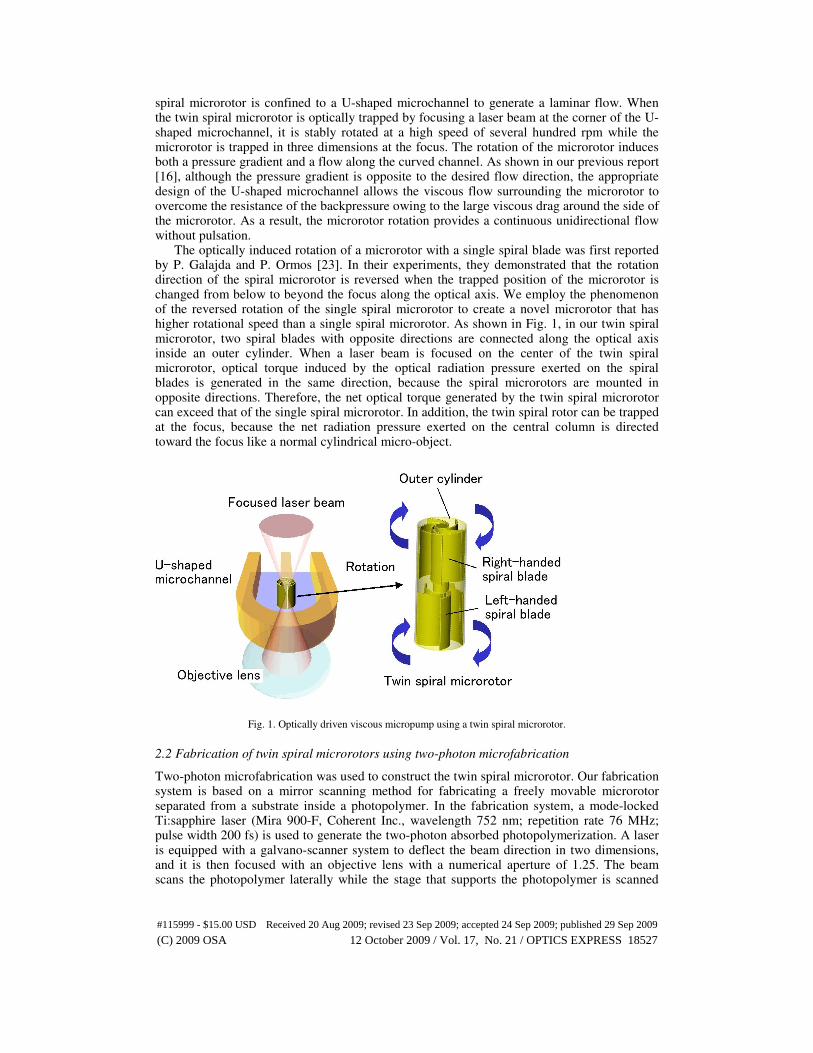
spiral microrotor is confined to a U-shaped microchannel to generate a laminar flow. When the twin spiral microrotor is optically trapped by focusing a laser beam at the corner of the U-shaped microchannel, it is stably rotated at a high speed of several hundred rpm while the microrotor is trapped in three dimensions at the focus. The rotation of the microrotor induces both a pressure gradient and a flow along the curved channel. As shown in our previous report [16], although the pressure gradient is opposite to the desired flow direction, the appropriate design of the U-shaped microchannel allows the viscous flow surrounding the microrotor to overcome the resistance of the backpressure owing to the large viscous drag around the side of the microrotor. As a result, the microrotor rotation provides a continuous unidirectional flow without pulsation.
The optically induced rotation of a microrotor with a single spiral blade was first reported by P. Galajda and P. Ormos [23]. In their experiments, they demonstrated that the rotation direction of the spiral microrotor is reversed when the trapped position of the microrotor is changed from below to beyond the focus along the optical axis. We employ the phenomenon of the reversed rotation of the single spiral microrotor to create a novel microrotor that has higher rotational speed than a single spiral microrotor. As shown in Fig. 1, in our twin spiral microrotor, two spiral blades with opposite directions are connected along the optical axis inside an outer cylinder. When a laser beam is focused on the center of the twin spiral microrotor, optical torque induced by the optical radiation pressure exerted on the spiral blades is generated in the same direction, because the spiral microrotors are mounted in opposite directions. Therefore, the net optical torque generated by the twin spiral microrotor can exceed that of the single spiral microrotor. In addition, the twin spiral rotor can be trapped at the focus, because the net radiation pressure exerted on the central column is directed toward the focus like a normal cylindrical micro-object.
Fig. 1. Optically driven viscous micropump using a twin spiral microrotor.
2.2 Fabrication of twin spiral microrotors using two-photon microfabrication
Two-photon microfabrication was used to construct the twin spiral microrotor. Our fabrication system is based on a mirror scanning method for fabricating a freely movable microrotor separated from a substrate inside a photopolymer. In the fabrication system, a mode-locked Ti:sapphire laser (Mira 900-F, Coherent Inc., wavelength 752 nm; repetition rate 76 MHz; pulse width 200 fs) is used to generate the two-photon absorbed photopolymerization. A laser is equipped with a galvano-scanner system to deflect the beam direction in two dimensions, and it is then focused with an objective lens with a numerical aperture of 1.25. The beam scans the photopolymer laterally while the stage that supports the photopolymer is scanned
#115999 - $15.00 USD Received 20 Aug 2009; revised 23 Sep 2009; accepted 24 Sep 2009; published 29 Sep 2009
(C) 2009 OSA 12 October 2009 / Vol. 17, No. 21 / OPTICS EXPRESS 18527
vertically, thereby moving the point of focus in three dimensions. By controlling both the galvano-scanner system and the stage with 3D computer-aided design data, we can fabricate the desired 3D microstructure, which even includes a freely movable micropart. After the 3D fabrication process, the unsolidified photopolymer is washed away with a solvent, leaving only the created microstructure. In our experiments, we used a commercial epoxy-type photopolymer (SCR-701, D-MEC Ltd.) as the microrotor and microchannel material.
2.3 Optical driving of single and twin spiral microrotors
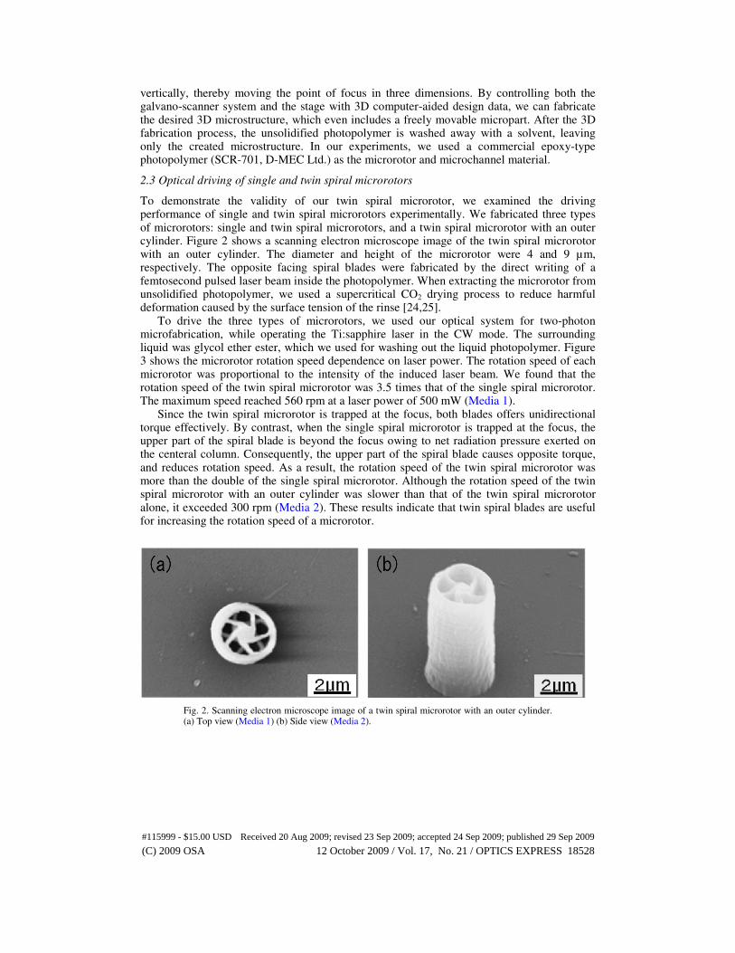
To demonstrate the validity of our twin spiral microrotor, we examined the driving performance of single and twin spiral microrotors experimentally. We fabricated three types of microrotors: single and twin spiral microrotors, and a twin spiral microrotor with an outer cylinder. Figure 2 shows a scanning electron microscope image of the twin spiral microrotor with an outer cylinder. The diameter and height of the microrotor were 4 and 9 µm, respectively. The opposite facing spiral blades were fabricated by the direct writing of a femtosecond pulsed laser beam inside the photopolymer. When extracting the microrotor from unsolidified photopolymer, we used a supercritical CO2 drying process to reduce harmful deformation caused by the surface tension of the rinse [24,25].
To drive the three types of microrotors, we used our optical system for two-photon microfabrication, while operating the Ti:sapphire laser in the CW mode. The surrounding liquid was glycol ether ester, which we used for washing out the liquid photopolymer. Figure 3 shows the microrotor rotation speed dependence on laser power. The rotation speed of each microrotor was proportional to the intensity of the induced laser beam. We found that the rotation speed of the twin spiral microrotor was 3.5 times that of the single spiral microrotor. The maximum speed reached 560 rpm at a laser power of 500 mW (Media 1).
Since the twin spiral microrotor is trapped at the focus, both blades offers unidirectional torque effectively. By contrast, when the single spiral microrotor is trapped at the focus, the upper part of the spiral blade is beyond the focus owing to net radiation pressure exerted on the centeral column. Consequently, the upper part of the spiral blade causes opposite torque, and reduces rotation speed. As a result, the rotation speed of the twin spiral microrotor was more than the double of the single spiral microrotor. Although the rotation speed of the twin spiral microrotor with an outer cylinder was slower than that of the twin spiral microrotor alone, it exceeded 300 rpm (Media 2). These results indicate that twin spiral blades are useful for increasing the rotation speed of a microrotor.
Fig. 2. Scanning electron microscope image of a twin spiral microrotor with an outer cylinder. (a) Top view (Media 1) (b) Side view (Media 2).
#115999 - $15.00 USD Received 20 Aug 2009; revised 23 Sep 2009; accepted 24 Sep 2009; published 29 Sep 2009
(C) 2009 OSA 12 October 2009 / Vol. 17, No. 21 / OPTICS EXPRESS 18528

Fig. 3. Microrotor rotation speeds dependence on laser power.
2.4 Finite element analysis of flow distribution of viscous micropump
The pumping performance of the viscous micropump with a single microrotor depends on several parameters including the width of the U-shaped microchannel, and the diameter and position of the microrotor. In our previous work, we demonstrated the flow rate dependence on microchannel width with a single disk microrotor 10 µm in diameter [16]. In this study, we examined the flow rate of the micropump with a twin spiral microrotor.
To optimize the micropump design, we analyzed the flow field inside the U-shaped microchannel using the two-dimensional (2D) finite element method (FEM) based on the Navier-Stokes equation. A commercially available multiphysics simulator (COMSOL ver.3.3) was used for the FEM analysis. The diameter of the twin spiral microrotor used in our simulation was 4 µm. The clearance between the rotor and the center partition was 4 µm. The pressures at the inlet and outlet of the linear channel were both 0 Pa. To analyze the flow generated by rotating the microrotor, we applied a velocity to the fluid around the microrotor.
The density and viscosity of the fluid were 0.96 x 10³ kg/m
3 and 1.92 x 10
−3 Pa·s,
respectively. These values agree with the parameters of the glycol ether ester used in the experiments described below.
2.5 Channel width optimization
We examined the pressure field, flow velocity and streamlines of the micropump by changing the width of the microchannel. As a result, we found that when the channel width was small, a large backflow was generated around the microrotor owing to the pressure gradient against the flow direction. On the other hand, when the channel width was wide, the pressure gradient was shallow. In this simulation, we found that the backflow disappeared when the channel width was larger than 6 µm. Figure 4 shows the dependence of the maximum flow velocity of the laminar flow on the channel width. The results indicated that the flow rate was saturated at a microchannel width of 10 µm with a 4 µm-diameter microrotor. Figure 5 shows typical simulation results for the flow velocity and streamlines of the micropump, which has a 10 µm-wide microchannel. Here, the viscous force applied by the spinning microrotor can be efficiently transferred from the inlet to the outlet through the U-shaped microchannel. Fluid can therefore be transported in the forward direction because there is sufficient viscous force against the backpressure caused by the rotation of the microrotor. A steady laminar flow is generated in the linear regions of the U-shaped microchannels.
#115999 - $15.00 USD Received 20 Aug 2009; revised 23 Sep 2009; accepted 24 Sep 2009; published 29 Sep 2009
(C) 2009 OSA 12 October 2009 / Vol. 17, No. 21 / OPTICS EXPRESS 18529

Fig. 4. Dependence of the maximum flow velocity of the laminar flow on channel width.
Fig. 5. Simulation results for the flow velocity and streamlines of a micropump with a 10 µm-width microchannel. (a) Flow velocity (b) Streamlines.
#115999 - $15.00 USD Received 20 Aug 2009; revised 23 Sep 2009; accepted 24 Sep 2009; published 29 Sep 2009
(C) 2009 OSA 12 October 2009 / Vol. 17, No. 21 / OPTICS EXPRESS 18530
2.6 Fabrication and driving of viscous micropump using twin spiral microrotor
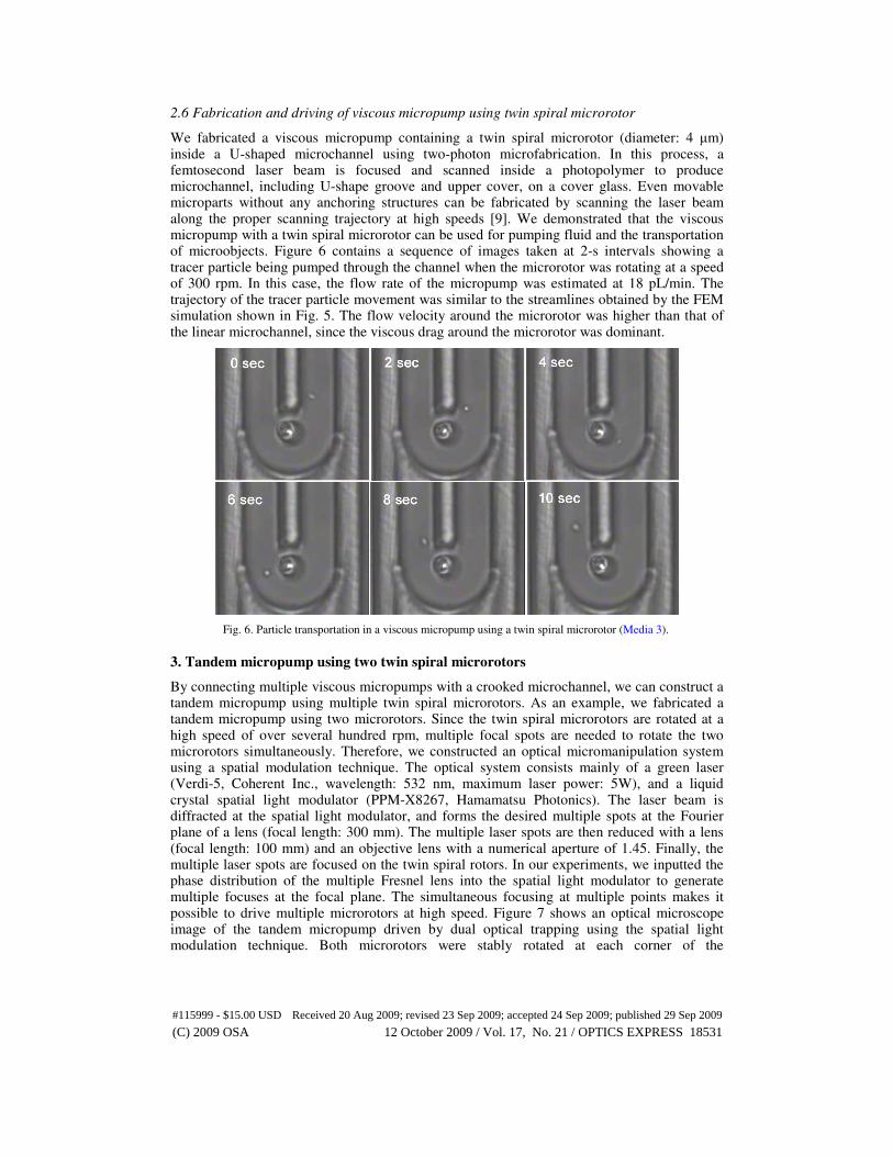
We fabricated a viscous micropump containing a twin spiral microrotor (diameter: 4 µm) inside a U-shaped microchannel using two-photon microfabrication. In this process, a femtosecond laser beam is focused and scanned inside a photopolymer to produce microchannel, including U-shape groove and upper cover, on a cover glass. Even movable microparts without any anchoring structures can be fabricated by scanning the laser beam along the proper scanning trajectory at high speeds [9]. We demonstrated that the viscous micropump with a twin spiral microrotor can be used for pumping fluid and the transportation of microobjects. Figure 6 contains a sequence of images taken at 2-s intervals showing a tracer particle being pumped through the channel when the microrotor was rotating at a speed of 300 rpm. In this case, the flow rate of the micropump was estimated at 18 pL/min. The trajectory of the tracer particle movement was similar to the streamlines obtained by the FEM simulation shown in Fig. 5. The flow velocity around the microrotor was higher than that of the linear microchannel, since the viscous drag around the microrotor was dominant.
Fig. 6. Particle transportation in a viscous micropump using a twin spiral microrotor (Media 3).
3. Tandem micropump using two twin spiral microrotors
By connecting multiple viscous micropumps with a crooked microchannel, we can construct a tandem micropump using multiple twin spiral microrotors. As an example, we fabricated a tandem micropump using two microrotors. Since the twin spiral microrotors are rotated at a high speed of over several hundred rpm, multiple focal spots are needed to rotate the two microrotors simultaneously. Therefore, we constructed an optical micromanipulation system using a spatial modulation technique. The optical system consists mainly of a green laser (Verdi-5, Coherent Inc., wavelength: 532 nm, maximum laser power: 5W), and a liquid crystal spatial light modulator (PPM-X8267, Hamamatsu Photonics). The laser beam is diffracted at the spatial light modulator, and forms the desired multiple spots at the Fourier plane of a lens (focal length: 300 mm). The multiple laser spots are then reduced with a lens (focal length: 100 mm) and an objective lens with a numerical aperture of 1.45. Finally, the multiple laser spots are focused on the twin spiral rotors. In our experiments, we inputted the phase distribution of the multiple Fresnel lens into the spatial light modulator to generate multiple focuses at the focal plane. The simultaneous focusing at multiple points makes it possible to drive multiple microrotors at high speed. Figure 7 shows an optical microscope image of the tandem micropump driven by dual optical trapping using the spatial light modulation technique. Both microrotors were stably rotated at each corner of the
#115999 - $15.00 USD Received 20 Aug 2009; revised 23 Sep 2009; accepted 24 Sep 2009; published 29 Sep 2009
(C) 2009 OSA 12 October 2009 / Vol. 17, No. 21 / OPTICS EXPRESS 18531

microchannel. The tandem micropump is useful for the long-distance transportation of microobjects such as living cells and microparticles.
Fig. 7. Optical microscope image of a tandem micropump driven by dual optical trapping (Media 4).
4. Conclusions
An optically driven viscous micropump with a twin spiral microrotor was developed by employing two-photon microfabrication. The twin spiral microrotor could be rotated at a high speed of over 500 rpm by focusing a laser beam, because the optical torque exerted on the left- and right-handed spiral blades was imposed in the same direction. In addition, a tandem micropump including two microrotors in a crooked microchannel was developed. The high-speed microrotors were simultaneously trapped and rotated by optical tweezers using a spatial light modulation technique. These viscous micropumps provide several advantages, including simplicity, ease of miniaturization, a readily controlled flow velocity, the production of a continuous flow, and the safe transportation of biological samples such as cells. In the near future, optically driven micropumps will be utilized for lab-on-a-chip devices where specific features such as an ultralow flow rate, steady continuous flows and the damage-free transportation of biological samples are required.
Acknowledgments
This research was partially supported by research grants from PRESTO, the Japan Science and Technology Agency, and from the Japan Society for the Promotion of Science (Grant-in-Aid Exploratory Research and Scientific Research in Priority Areas: System Cell Engineering by Multi-scale Manipulation, and Grant-in-Aid for Challenging Exploratory Research). The authors also acknowledge Fluid Power Technology Promotion Foundation for its support.
#115999 - $15.00 USD Received 20 Aug 2009; revised 23 Sep 2009; accepted 24 Sep 2009; published 29 Sep 2009
(C) 2009 OSA 12 October 2009 / Vol. 17, No. 21 / OPTICS EXPRESS 18532