Embed Size (px)
Citation preview

OpticalLink C8000
EPON OLT Operation Manual
Wuhan Yangtze Optical Technology Co., Ltd. http://www.yotc.com.cn Manual Version: YOT 2.142.020-UM_A06 Product Version: RELEASE V400

Statement
Copyright ©2009 Wuhan Yangtze Optical Technology Co., Ltd. All Rights
Reserved.
No part of this manual may be reproduced or transmitted in any form or by any
means without the prior written consent of Wuhan Yangtze Optical Technology
Co., Ltd.
OpticalLink, OpView, OpticalLink, OpView and are the
trademarks of Wuhan Yangtze Optical Technology Co., Ltd. All other
trademarks that may be mentioned in this manual are the properties of their
respective owners.
The information in this document is subject to update from time to time due to
upgrading of product versions or other reasons. Unless otherwise agreed, the
manual is for reference only. All statements, information and recommendations
in this manual do not constitute the warranty of any kind, express or implied.
To obtain the latest information, please access to: http://www.yotc.com.cn
Technical Support
Wuhan Yangtze Optical Technology Co., Ltd. can provide a full range of
technical supports to customers.
In case of problems, users purchasing the products from the agents of Wuhan
Yangtze Optical Technology Co., Ltd can directly contact with the sales agent.
In case of problems, users purchasing the products directly from Wuhan
Yangtze Optical Technology Co., Ltd, can contact with the nearest office of
Yangtze Optical or the headquarters of Yangtze Optical.

Hotline: 027-67887399; Fax: 027-67887678
Technical Support Email: [email protected]
Headquarters Address: Wuhan Yangtze Optical Technology Co., Ltd., #4 Guanshan Er Road, Wuhan China 430073
Website: http://www.yotc.com.cn


Wuhan Yangtze Optical Technology Co., Ltd. OpticalLink C8000 EPON OLT Operation Manual
I
About This Manual
Related Documentation
Manual Description
OpticalLink C8000 EPON OLT Command Manual
It provides the commands for the general information, system and equipment, VLAN, port, port isolation, OLT, ONU, RSTP, Link-Aggregation, Mirror , MAC address table, QoS, ACL, IGMP, performance, alarm and inband network administration and other modules of C8000 OLT devices.
OpticalLink C8000 EPON OLT Installation Manual
It provides the product introduction, service single board, pre-installation preparation, installation, hardware maintenance, software maintenance and troubleshooting of C8000 OLT.
Organization
OpticalLink C8000 EPON OLT Operation Manual mainly introduces the general information, logging-in, command line interface and view, system and equipment operation, VLAN, OLT port, PON port isolation, PON, ONU, RSTP, Trunk, Mirror, MAC address table, QoS, ACL, IGMP, performance, alarm and network administration and other configuration operations. To prevent possible operation problems, the loss of configuration or the disconnection of services, please read this manual carefully. The manual is organized as follows: Chapter 1 Overview: Elaborates the data acquisition methods, the relation
between information and versions and the product introduction. Chapter 2 Login the OLT device: Elaborates the local and remote login
operation of the OLT device. Chapter 3 Command Line Interface and View: Elaborates the system
view and the operation of the command line interface. Chapter 4 System Upgrading: Elaborates the commands relevant to
system management, including upgrading and configuration files, network tools and restarting.

Wuhan Yangtze Optical Technology Co., Ltd. OpticalLink C8000 EPON OLT Operation Manual
II
Chapter 5 Device Configuration Management: Elaborates the configuration management of the device, including the system date and time, time zone, host name management and slot position configuration.
Chapter 6 VLAN Configuration Management: Elaborates the operation of VLAN configuration.
Chapter 7 OLT Port Configuration Management: Elaborates the OLT port configuration, including the basic configuration of the port, broadcast/multicast and unknown unicast suppression, flow control, loop-back, port speed limit, display of basic configuration of the port, and maintenance, etc.
Chapter 8 PON Port Isolation Configuration Management: Elaborates the isolation operation of PON port.
Chapter 9 PON Configuration Management: Elaborates the PON configuration management operation.
Chapter 10 ONU Configuration Management: Elaborates the configuration management of the ONU device, the configuration management of the ONU port, classification and marking configuration management and ONU SLA configuration management.
Chapter 11 RSTP Configuration Management: Elaborates the rapid spanning tree configuration management.
Chapter 12 Link Aggregation Configuration Management: Elaborates the configuration management operation of link aggregation.
Chapter 13 Port Mirroring Configuration Management: Elaborates the configuration management operation relevant to port mirroring.
Chapter 14 MAC Address Table Configuration Management: Elaborates the layer 2 MAC address table configuration management.
Chapter 15 QoS Configuration Management: Elaborates the configuration management operations relevant to QoS.
Chapter 16 ACL Configuration Management: Elaborates the ACL configuration management operations.
Chapter 17 Layer 3 Static Router Management: Elaborates the configuration management operation relevant to the layer 3 static router.
Chapter 18 Multicast Configuration Management: Elaborates the IGMP configuration management operations.
Chapter 19 Performance Configuration Management: Elaborates the performance configuration management operations.
Chapter 20 Alarm Configuration Management: Elaborates the alarm configuration management operation.
Chapter 21 Network Management Configuration: Elaborates the network management configuration.

Wuhan Yangtze Optical Technology Co., Ltd. OpticalLink C8000 EPON OLT Operation Manual
III
Conventions
1. Common Conventions
Convention Description
Song typeface The text is in Song typeface. Boldface In addition to the heading 1 that is in Song typeface
and Bold, the headings of other levels are in bold. Regular Script Caution, tip and the like are in regular script, and
lines are provided before and after such contents to separate from the text.
Arial All are in Arial with the exception of the headings.
2. Command Line Conventions
Convention Description
Boldface The keywords of a command line are in Boldface. italic Command arguments are in italic.
[ ] Items (keywords or arguments) in square brackets [ ] are optional.
(x | y | ... ) Alternative items are grouped in braces and separated by vertical bars. One is selected.
[x|y|…] Optional alternative items are grouped in square brackets and separated by vertical bars. One or none is selected.
<x-y> One from x to y is selected. $ It is the comments.
3. Keyboard Conventions
Convention Description
Character in angular brackets
Button names are inside angle brackets. For example, <Enter>, <Tab>, <Backspace>, <a> and <?> are respectively Enter, Tab, Backspace, Lowercase Letter a and ?.
< Key 1 + Key 2> Key combination, for example, <Ctrl+Alt+A> is composed of "Ctrl", "Alt" and "A".
< Key 1, Key 2> Press the first key first, release, and then press the second key. For example, <Alt, F>, press <Alt> first, release and then press <F> key.

Wuhan Yangtze Optical Technology Co., Ltd. OpticalLink C8000 EPON OLT Operation Manual
IV
4. Symbols
To make sure that you perform certain tasks properly, take note of the following symbols used throughout this manual.
Caution: Means reader be careful. Improper operation may cause data loss or damage to equipment.
Warning: Provides information to prevent injury due to improper operation.
Note: Provides tips to aid in completing a task.
5. Tips
The command lines of the system are case sensitive.

Wuhan Yangtze Optical Technology Co., Ltd. OpticalLink C8000 EPON OLT Operation Manual
V
Abbreviations
ACL Access Control List
CDR Call Detail Record
CVLAN Customer VLAN
DA Destination Address
DBA Dynamic Bandwidth Allocation
EPON Ethernet Passive Optical Network
FEC Forward Error Correction
IGMP Internet Group Management Protocol
LLID Logical Link Identifier
LPU Line Process Unit
MAC Medium Access Control
OLT Optical Line Terminal
ONU Optical Network Unit
QoS Quality of Service
RSTP Rapid Spanning Tree Protocol
SA Source Address
SCU Switch Control Unit
SLA Service Level Agreement
SNI Service Network Interface
SNMP Simple Network Management Protocol
RTT Round Trip Time
UNI User Network Interface
VLAN Virtual Local Area Network
VoIP Voice over IP
C&M Classification&Marking


Wuhan Yangtze Optical Technology Co., Ltd. OpticalLink C8000 EPON OLT Operation Manual
1
TABLE OF CONTENTS
1 OVERVIEW .............................................................................................................................................. 1
1.1 DOCUMENTATION OBTAINING .......................................................................................................................... 1
1.2 SOFTERWARE RELEASE NOTES .......................................................................................................................... 1
1.2.1 Software Version of Manual ................................................................................................................. 1
1.2.2 Related Documentation ........................................................................................................................ 2
1.3 PRODUCT PROFILE ......................................................................................................................................... 2
1.3.1 Introduction to Switch Control Unit of C8000 OLT Device .................................................................... 2
1.3.2 Integration Relation between Switch Control Unit and Service Board ................................................. 3
1.3.3 Software Features ................................................................................................................................. 3
1.4 NETWORK APPLICATION .................................................................................................................................. 5
2 LOGIN THE OLT DEVICE ............................................................................................................................ 6
2.1 LOCAL LOGIN BY CONSOLE PORT ....................................................................................................................... 6
2.1.1 Connection of Console Cable ................................................................................................................ 6
2.1.2 Configuring the Terminal Parameters ................................................................................................... 6
2.1.3 Start Up the Interface ......................................................................................................................... 10
2.2 LOCAL LOGIN BY TELNET ................................................................................................................................ 11
2.2.1 Connection of Cable ........................................................................................................................... 11
2.2.2 Set up the Parameters of the Outband Management Port of Local C8000 ........................................ 12
2.2.3 Set up the Network Card Parameter of the Terminal PC .................................................................... 12
2.2.4 Set up the Parameters for Telnet Terminal ......................................................................................... 14
2.2.5 Telnet Connection Interface ............................................................................................................... 17
2.3 REMOTE LOGIN BY TELNET ............................................................................................................................. 18
2.3.1 Connection of PC Cable ...................................................................................................................... 18
2.3.2 Set up the Parameters of Inband Management Port of Local C8000 ................................................. 18
2.3.3 Set up the Parameters of the Terminal PC Network Card ................................................................... 18
2.3.4 Set up the Parameters for Telnet Terminal ......................................................................................... 18
2.3.5 Telnet Connection Interface ............................................................................................................... 18
3 COMMAND LINE INTERFACE AND VIEW ................................................................................................ 19
3.1 INTRODUCTION TO COMMAND LINE INTERFACE ................................................................................................. 19
3.2 COMMAND LEVEL LINE AND COMMAND LINE VIEW ............................................................................................ 19
3.2.1 Switching of View Levels .................................................................................................................... 20
3.2.2 Setup of the view switch password .................................................................................................... 20
3.2.3 Command View .................................................................................................................................. 21
3.3 CLI FEATURES ............................................................................................................................................. 22
3.3.1 Online Help for Command Line .......................................................................................................... 22
3.3.2 Characteristics of command line display ............................................................................................ 25
3.3.3 Command History ............................................................................................................................... 26
3.3.4 Error Message of Command Line ........................................................................................................ 26
3.3.5 Features of Command Line Editing ..................................................................................................... 27
4 SYSTEM MANAGEMENT ........................................................................................................................ 29

Wuhan Yangtze Optical Technology Co., Ltd. OpticalLink C8000 EPON OLT Operation Manual
2
4.1 FILE SYSTEM CONFIGURATION ........................................................................................................................ 29
4.1.1 Introduction to File System ................................................................................................................ 29
4.1.2 Operations on Directory ..................................................................................................................... 29
4.1.3 Operations on File .............................................................................................................................. 30
4.1.4 Operation on Storage Device .............................................................................................................. 30
4.1.5 Example of File System Application .................................................................................................... 30
4.2 SYSTEM UPGRADE ................................................................................................................................... 32
4.2.1 Introduction to System Upgrade ......................................................................................................... 32
4.2.2 Upgrading the System ......................................................................................................................... 33
4.2.3 System Upgrade Example ................................................................................................................... 34
4.3 CONFIGURING THE FILE ................................................................................................................................. 35
4.4 OPERATING THE NETWORK TOOLS ................................................................................................................... 35
4.4.1 Introduction to Relevant Knowledge about Network Tools ................................................................ 35
4.4.2 Introduction to FTP ............................................................................................................................. 35
4.4.3 Introduction to Telnet ......................................................................................................................... 35
4.4.4 Introduction to Ping ............................................................................................................................ 36
4.4.5 Operating the Network Tools .............................................................................................................. 36
4.5 RESTARTING ................................................................................................................................................ 36
5 DEVICE CONFIGURATION MANAGEMENT ............................................................................................. 37
5.1 MANAGING TIME, TIME ZONE AND HOST NAME ............................................................................................... 37
5.2 MONITORING OF THE POWER TO FAN .............................................................................................................. 38
5.2.1 Introduction to Power to the Fan ....................................................................................................... 38
5.2.2 Fan Power Monitoring ........................................................................................................................ 38
5.3 SLOT BOARD MANAGEMENT .......................................................................................................................... 39
5.3.1 Introduction to Slot Management ...................................................................................................... 39
5.3.2 Slot Management ............................................................................................................................... 39
5.3.3 Slot Management Operation Example ................................................................................................ 40
5.4 ACTIVE/STANDBY CHANGEOVER MANAGEMENT ................................................................................................ 41
5.4.1 Introduction to Active/Standby Changeover ...................................................................................... 41
5.4.2 Forced Active/Standby Changeover .................................................................................................... 42
6 VLAN CONFIGURATION MANAGEMENT ................................................................................................ 43
6.1 VLAN CONFIGURATION MANAGEMENT ........................................................................................................... 43
6.1.1 Introduction to VLAN .......................................................................................................................... 43
6.1.2 OLT port-based VLAN .......................................................................................................................... 47
6.1.3 ONU Port-based VLAN ........................................................................................................................ 51
6.2 OLT VLAN CONFIGURATION AND APPLICATION ................................................................................................. 53
6.2.1 Basic Configuration of VLAN ............................................................................................................... 53
6.2.2 VLAN Multicast Forwarding Configuration ......................................................................................... 54
6.2.3 802.1Q-based CVLAN Hybrid Application ........................................................................................... 55
6.2.4 802.1ad-based SVLAN Hybrid Application .......................................................................................... 59
6.2.5 VLAN Transparent Application ............................................................................................................ 63
6.2.6 VLAN Translate Application ................................................................................................................ 66
6.2.7 VLAN QinQ Application ....................................................................................................................... 71
6.3 ONU VLAN CONFIGURATION ........................................................................................................................ 75

Wuhan Yangtze Optical Technology Co., Ltd. OpticalLink C8000 EPON OLT Operation Manual
3
6.3.1 VLAN Transparent Transmission ......................................................................................................... 75
6.3.2 VLAN Tag ............................................................................................................................................. 77
6.3.3 VLAN Translation ................................................................................................................................ 80
7 OLT PORT CONFIGURATION MANAGEMENT ......................................................................................... 85
7.1 INTRODUCTION TO OLT PORT CONFIGURATION ................................................................................................. 85
7.1.1 Basic Configuration of OLT Port .......................................................................................................... 86
7.1.2 Broadcast/ Multicast/ Unknown Unicast Storm Suppression Configuration ...................................... 87
7.1.3 Configuring the Port Flow Control Function ....................................................................................... 88
7.1.4 Configuring the loop-back test of the port ......................................................................................... 89
7.1.5 Configuring the speed limitation of port ............................................................................................ 89
7.1.6 Display and Maintenance of the Basic Configuration of Port ............................................................. 91
7.2 OLT PORT CONFIGURATION EXAMPLE .............................................................................................................. 91
7.2.1 Network Requirement ........................................................................................................................ 91
7.2.2 Network Diagram ................................................................................................................................ 91
7.2.3 Configuration Procedure ..................................................................................................................... 91
8 PON PORT ISOLATION CONFIGURATION MANAGEMENT ...................................................................... 93
8.1 INTRODUCTION TO PON PORT ISOLATION ........................................................................................................ 93
8.2 CONFIGURATION OF PON PORT ISOLATION ....................................................................................................... 93
8.3 DISPLAY OF PON PORT ISOLATION .................................................................................................................. 93
8.4 PON PORT ISOLATION CONFIGURATION EXAMPLE .............................................................................................. 94
8.4.1 Network Requirement ........................................................................................................................ 94
8.4.2 Network Diagram ................................................................................................................................ 94
8.4.3 Configuration Procedure ..................................................................................................................... 94
9 PON CONFIGURATION MANAGEMENT .................................................................................................. 95
9.1 DOWNLINK ENCRYPTION MANAGEMENT .......................................................................................................... 95
9.1.1 Configuring the Downlink Encryption Parameters of OLT .................................................................. 95
9.1.2 Configuring the Encryption Status of ONU ......................................................................................... 96
9.1.3 Downlink Encryption Configuration Example ..................................................................................... 96
9.2 CONFIGURING THE MAXIMUM DISTANCE ......................................................................................................... 98
9.2.1 Configuring the Maximum Distance ................................................................................................... 98
9.2.2 Maximum Distance Configuration Example ........................................................................................ 99
9.3 CONFIGURING THE DLF FORWARDING POLICY ................................................................................................... 99
9.3.1 Configuring the Forwarding Strategy of DLF ..................................................................................... 100
9.3.2 DLF Forwarding Strategy Configuration Example ............................................................................. 101
9.4 CONFIGURE THE PORT CONTROL ................................................................................................................... 101
9.4.1 Configure the Port Control ................................................................................................................ 102
9.4.2 Example of Port Control Configuration ............................................................................................. 103
9.5 CONFIGURE THE PROTECTION SWITCHING OF TRUNK FIBER ................................................................................ 105
9.5.1 Configuring the Trunk Fiber Protection Switching ............................................................................ 106
9.5.2 Example of Trunk Fiber Protection Switching Configuration ............................................................ 106
10 ONU CONFIGURATION MANAGEMENT ............................................................................................... 109
10.1 ONU DEVICE CONFIGURATION MANAGEMENT ........................................................................................... 109

Wuhan Yangtze Optical Technology Co., Ltd. OpticalLink C8000 EPON OLT Operation Manual
4
10.1.1 ONU Authorization Management ................................................................................................... 109
10.1.2 Configuring the Management Information of SFU-based ONU ...................................................... 109
10.1.3 Configuring the ONU Automatic Binding Strategy .......................................................................... 110
10.1.4 Configuring the ONU Manual Binding Strategy .............................................................................. 110
10.1.5 Example of ONU Binding Strategy Configuration ........................................................................... 111
10.1.6 Restarting and Deregistering .......................................................................................................... 113
10.1.8 FEC Configuration ........................................................................................................................... 115
10.1.9 Configure the ONU Port Isolation ................................................................................................... 115
10.1.10 Configuring the Loop Detection of the Port ................................................................................. 116
10.1.11 P2P Operation ............................................................................................................................... 116
10.1.12 VOIP Port Operation ..................................................................................................................... 118
10.1.12.5 Setup of WAN IP ........................................................................................................................ 125
10.2 ONUPORT CONFIGURATION MANAGEMENT .............................................................................................. 125
10.2.1 Basic Configuration of ONU Port .................................................................................................... 126
10.2.3 Configuring the Flow Control of the Port ........................................................................................ 127
10.2.4 ONU Port’s Flow Control Configuration Example ........................................................................... 127
10.2.5 Configuring the Port Rate Limitation .............................................................................................. 128
10.2.7 Display and Maintenance of the Basic Configuration of Port ......................................................... 130
10.3 CLASSIFICATION AND MARKING CONFIGURATION MANAGEMENT ................................................................... 130
10.3.1 Introduction to Classification and Marking ..................................................................................... 130
10.3.2 Classification and tag Template Operation ..................................................................................... 131
10.3.3 Classification and Marking Configuration Example ........................................................................ 132
10.4 SLA CONFIGURATION MANAGEMENT ....................................................................................................... 133
10.4.1 Introduction to SLA ......................................................................................................................... 133
10.4.2 Configuring SLA ............................................................................................................................... 134
10.4.3 SLA Configuration Example ............................................................................................................. 136
11 RSTP CONFIGURATION MANAGEMENT ............................................................................................... 137
11.1 INTRODUCTION TO RSTP PROTOCOL ......................................................................................................... 137
11.2 OLT RSTP CONFIGURATION MANAGEMENT .............................................................................................. 144
11.2.1 List of RSTP Configuration Tasks ..................................................................................................... 144
11.2.2 Enable/Disable the Spanning Tree Features of Device ................................................................... 145
11.2.3 Enable/Disable the Spanning Tree Features of Port ....................................................................... 145
11.2.4 Configure the Working Mode of Spanning Tree Protocol ............................................................... 145
11.2.5 Configure the Bridge Priority of Device .......................................................................................... 146
11.2.6 Configure the Forward Delay Characteristics of Device .................................................................. 147
11.2.7 Configure the Hello Time Characteristics of Device ....................................................................... 147
11.2.8 Configure the Max Age Characteristics of Device ........................................................................... 148
11.2.9 Configure the Maximum Transmission Speed of a Specific Port .................................................... 149
11.2.10 Configure the Specific Port to be Edge Port or Not ...................................................................... 149
11.2.11 Configure the Path Cost of a Specific Port .................................................................................... 150
11.2.12 Configure the Priority of a Specific Port ....................................................................................... 151
11.2.13 Configure the Specific Port to be Connected with Point to Point Link or not ............................... 152
11.3 MONITORING AND MAINTENANCE OF OLT RSTP ........................................................................................ 153
11.4 CONFIGURE ONU RSTP ........................................................................................................................ 154
11.4.1 Enable/disable the Spanning Tree Characteristics of ONU ............................................................. 154

Wuhan Yangtze Optical Technology Co., Ltd. OpticalLink C8000 EPON OLT Operation Manual
5
11.5 MONITORING AND MAINTENANCE OF ONU RSTP ...................................................................................... 154
12 LINK AGGREGATION CONFIGURATION MANAGEMENT ....................................................................... 156
12.1 INTRODUCTION TO LINK AGGREGATION ..................................................................................................... 156
12.2 LINK AGGREGATION GROUP CONFIGURATION ............................................................................................. 157
12.3 LINK AGGREGATION GROUP CONFIGURATION EXAMPLE ................................................................................ 158
12.3.1 Network Requirement .................................................................................................................... 158
12.3.2 Network Diagram ............................................................................................................................ 159
12.3.3 Configuration Procedure ................................................................................................................. 159
13 PORT MIRRORING CONFIGURATION MANAGEMENT .......................................................................... 160
13.1 INTRODUCTION TO PORT MIRRORING ....................................................................................................... 160
13.2 PORT MIRRORING CONFIGURATION .......................................................................................................... 160
13.3 PORT MIRRORING CONFIGURATION EXAMPLE ............................................................................................ 162
13.3.1 Network Requirement .................................................................................................................... 162
13.3.2 Network Diagram ............................................................................................................................ 163
13.3.3 Configuration Procedure ................................................................................................................. 163
14 MAC ADDRESS CONFIGURATION MANAGEMENT ................................................................................ 164
14.1 INTRODUCTION TO MAC ADDRESS ........................................................................................................... 164
14.2 OLT MAC ADDRESS MANAGEMENT ......................................................................................................... 167
14.2.1 Configure the Aging Time of MAC Address Table ........................................................................... 167
14.2.2 Configure the MAC Address Table Entries ...................................................................................... 168
14.2.3 Show MAC Address Table Configuration ......................................................................................... 169
14.2.4 OLT MAC Address Management Configuration Example ................................................................ 169
14.3 ONU MAC ADDRESS MANAGEMENT ....................................................................................................... 170
14.3.1 Configure the Aging Time of MAC Address Table ........................................................................... 170
14.3.2 Empty the ONU MAC Address Table ............................................................................................... 171
14.3.3 ONU MAC Address Management Configuration Example .............................................................. 171
14.4 RESTRICTION ON ONU PORT MAC ADDRESS ............................................................................................. 172
14.4.1 ONU Port MAC Address Restriction Configuration Example: .......................................................... 173
15 QOS CONFIGURATION MANAGEMENT ................................................................................................ 175
15.1 INTRODUCTION TO QOS ......................................................................................................................... 175
15.1.1 Traffic .............................................................................................................................................. 175
15.1.2 Traffic Classification ........................................................................................................................ 175
15.1.3 Priority ............................................................................................................................................ 175
15.1.4 Priority Re-tagging ...........................................................................................................................176
15.1.5 Packet Filtering ................................................................................................................................176
15.1.6 Traffic Policing ..................................................................................................................................176
15.1.7 Congestion Management ............................................................................................................... 177
15.2 QUEUE SCHEDULING .............................................................................................................................. 177
15.2.1 Strict Priority Scheduling ................................................................................................................ 178
15.2.2 Round Robin (RR) Scheduling ......................................................................................................... 178
15.2.3 Weighted Round Robin(WRR) Scheduling ...................................................................................... 179
15.2.4 Scheduling combined with Strict Priority and Weighted Round Robin (SP + WRR) ........................ 180

Wuhan Yangtze Optical Technology Co., Ltd. OpticalLink C8000 EPON OLT Operation Manual
6
15.3 CONFIGURING THE QOS ......................................................................................................................... 180
15.3.1 Configuring the OLT QoS ................................................................................................................. 180
15.3.2Configure ONU QoS ......................................................................................................................... 184
16 ACL CONFIGURATION MANAGEMENT ................................................................................................. 187
16.1 INTRODUCTION TO ACL .......................................................................................................................... 187
16.1.1 Mode of Application of ACL in OLT ................................................................................................. 188
16.2 ACL CONFIGURATION ............................................................................................................................ 188
16.2.1 Configuring the ACL list ................................................................................................................... 188
16.3 ACL Rule Configuration ...................................................................................................................... 191
16.4 Applying the ACL Rules to the Port .................................................................................................... 195
16.5 ACL Configuration Example ................................................................................................................ 196
17 LAYER 3 STATIC ROUTER MANAGEMENT ............................................................................................ 198
17.1 INTRODUCTION TO L3 STATIC ROUTER ....................................................................................................... 198
17.1.1 Network Requirement .................................................................................................................... 199
17.1.2 Network Diagram ............................................................................................................................ 199
17.1.3 Configuration Procedure ................................................................................................................. 199
18 MULTICAST CONFIGURATION MANAGEMENT ................................................................................... 202
18.1 INTRODUCTION TO MULTICAST ................................................................................................................ 202
18.1.1 Multicast Frame .............................................................................................................................. 202
18.1.2 Introduction to Multicast Address .................................................................................................. 205
18.1.3 Multicast Management Protocol IGMP .......................................................................................... 208
18.2 MULTICAST CONFIGURATION ................................................................................................................... 211
18.2.1 Basic Configuration of OLT Multicast .............................................................................................. 211
18.2.2 Basic Configuration of ONU Multicast ............................................................................................ 212
18.2.3 igmp proxy Protocol Parameter Configuration ............................................................................... 215
18.2.4 igmp Channel Table Configuration .................................................................................................. 216
18.2.5 Configuration of igmp Controllable Multicast Preview Parameter ................................................. 217
18.2.6 Configuration of igmp Controllable Multicast Authority Table ....................................................... 219
18.2.7 Multicast Vlan Configuration .......................................................................................................... 220
18.3 IGMP CONTROLLABLE MULTICAST CONFIGURATION .................................................................................... 221
18.3.1 Configuration of OLT IGMP Controllable Multicast ......................................................................... 221
18.3.2 ONU IGMP Controllable Multicast Configuration ........................................................................... 223
18.3.3 IGMP Controllable Multicast Configuration Example ..................................................................... 224
18.4 IGMP PROXY MULTICAST CONFIGURATION ................................................................................................ 229
18.5 OLT IGMP PROXY MULTICAST CONFIGURATION ......................................................................................... 229
18.5.1 ONU IGMP Proxy Multicast Configuration ...................................................................................... 230
18.5.2 IGMP Proxy Multicast Configuration Example ................................................................................ 231
19 PERFORMANCE CONFIGURATION MANAGEMENT .............................................................................. 235
19.1 INTRODUCTION TO PERFORMANCE CONFIGURATION .................................................................................... 235
19.2 PERFORMANCE CONFIGURATION .............................................................................................................. 236
19.2.1 OLT Performance Configuration ...................................................................................................... 236
19.2.2 ONU Performance Configuration .................................................................................................... 238

Wuhan Yangtze Optical Technology Co., Ltd. OpticalLink C8000 EPON OLT Operation Manual
7
19.3 Performance Configuration Example ................................................................................................. 239
20 ALARM CONFIGURATION MANAGEMENT ........................................................................................... 241
20.1 INTRODUCTION TO ALARM CONFIGURATION ............................................................................................... 241
20.2 INTRODUCTION TO ALARM CONFIGURATION TASK ....................................................................................... 241
20.3 CONFIGURE SNMP TRAP SERVER ............................................................................................................... 242
20.4 CONFIGURE ALARM INFORMATION SHIELD ................................................................................................. 242
20.5 ALARM CONFIGURATION EXAMPLE ........................................................................................................... 243
20.6 ALARM CONFIGURATION DISPLAY AND MAINTENANCE ................................................................................. 244
21 NETWORK MANAGEMENT CONFIGURATION ........................................................................ 245
21.1 INTRODUCTION TO NETWORK MANAGEMENT MODE ................................................................................... 245
21.2 DEFAULT NETWORK MANAGEMENT CONFIGURATION ................................................................................... 248
21.3 OUTBAND NETWORK MANAGEMENT CONFIGURATION ................................................................................. 249
21.4 INBAND NETWORK MANAGEMENT CONFIGURATION .................................................................................... 249


Wuhan Yangtze Optical Technology Co., Ltd. OpticalLink C8000 EPON OLT Operation Manual
1
1 OVERVIEW
1.1 Documentation Obtaining
Wuhan Yangtze Optical Technology Co., Ltd. offers a variety of means for data acquisition to ensure the user can get the product-related information and the documents of new characteristics in a timely manner. The main data acquisition mode is the CD-ROM delivered along with the device.
YOTC provides a CD-ROM delivered along with each device. The CD-ROM describes the supporting electronic manuals of the product of the model, including operation manual, command manual, installation manual and compatibility manual (optional). After the user installs the browser in the CD-ROM, the desired content can be easily searched by operation interface.
The information in this document is subject to update from time to time due to upgrading of product versions or other reasons, while the contents of the CD-ROM may not be updated in a timely manner. Unless otherwise agreed, the manual is for reference only. All statements, information and recommendations in this manual do not constitute the warranty of any kind, express or implied. To obtain the latest software version, please access to YOTC website.
1.2 Softerware Release Notes
Due to the upgrading of product software version, the new software characteristics may be added in the new version. The user can get the relevant documents of new characteristics by releasing the supporting information through the software version.
1.2.1 Software Version of Manual
OpticalLink C8000 EPON OLT Operation Manual and OpticalLink C8000 EPON OLT Command Line Manual have the V400R007 software versions of C8000 products.

Wuhan Yangtze Optical Technology Co., Ltd. OpticalLink C8000 EPON OLT Operation Manual
2
1.2.2 Related Documentation
Table 1-2 List of Supporting Manuals
Manual Version
OPTICALLINK C8000 EPON OLT Installation Manual V3.0
OPTICALLINK C8000 EPON OLT Operation Manual V3.0
OPTICALLINK C8000 EPON OLT Command Line Manual V3.0
1.3 Product Profile
EPON (Ethernet Passive Optical Network) products of Wuhan Yangtze Optical Technology Co., Ltd. include OLT (Optical Line Terminal) devices and ONU (Optical Network Unit) devices, providing FTTH (Fiber To The Home) solution and FTTB (Fiber To The Building) solution and the like.
The OpticalLink C8000 product described in the manual is the carrier-grade EPON OLT device of Wuhan Yangtze Optical Technology Co., Ltd. specifically for large-scale access applications. The product not only meets the requirements of IEEE802.3 standard and the technical requirements of China Telecom's EPON equipment, but also is provided with many user interfaces and circuit boards; at the same time, the product can provide the powerful network management function and achieve the flexible networking and management of system, suitable for the application in the edge of metropolitan area network, the access layer of telecom network and the convergence layer/ access layer of enterprise network. The C8000 product has the powerful switching function, excellent network availability, upgradability, high performance and powerful network control capacity.
1.3.1 Introduction to Switch Control Unit of C8000 OLT Device
The switch control unit is the core of C8000 OLT device. The models of the switch control unit included in the C8000 OLT device are as follows:
SCU-A: Only switch control unit, without service network interface.
SCU-B: switch control unit of 1 port 10 GBASE-R (XFP) + 2 port10 GBASE-CX4 gigabit Ethernet.

Wuhan Yangtze Optical Technology Co., Ltd. OpticalLink C8000 EPON OLT Operation Manual
3
Table 1-3 List of Characteristics Indicators of the Switch Control Unit
Item Switch Capacity
Packet Switching Rate
Number of VLAN
MAC Address Table
Routing Table
SCU-A 96Gbit/s 72Mpps 4K 16K 8K
SCU-B 136Gbit/s 102Mpps 4K 16K 8K
1.3.2 Integration Relation between Switch Control Unit and Service Board
Table 1-4 Types of Service Boards Supported by Switch Control Unit
Item SCU-A SCU-B
LPU2P √ √
LPU4 √ √
SLU √ √
1.3.3 Software Features
Table 1-5 Software Features Module Features Command line interface and view
Supporting a variety of view modes and switching between views
Supporting command line interface Supporting online help
System management
Supporting the file system-related operations Supporting operations of upgrade and configuration file Supporting common network tools Supporting the restarting operations of device and board
Device configuration management
Supporting the configuration of time, time zone and host name
Supporting the monitoring of fan and power supply Supporting the setup and management of slots
VLAN configuration management
Supporting the VLAN in line with 802.1Q Supporting the VLAN based on port
OLTport configuration management
Supporting broadcast / multicast / unicast suppression; Supporting 802.3x flow control; Supporting the enabling and disabling of ports;

Wuhan Yangtze Optical Technology Co., Ltd. OpticalLink C8000 EPON OLT Operation Manual
4
Supporting burst frame length; Supporting hybrid VLAN, VLAN transparent
transmission, VLAN switching and VLAN stacking Supporting speed limitation of port Supporting port priority Supporting loop-back of port Supporting the setup and modification of tpid
PON port isolation
Two-layer isolation between PON ports
PON Configuration Management
Supporting downlink encryption Supporting the configuration of maximum distance Supporting DLF forwarding policy Supporting port control Supporting the switching of trunk fiber protection
ONU Configuration Management
Supporting the authorization management of ONU Supporting the restart and de-registration of ONU Supporting FEC and encryption switch Supporting the user port isolation of ONU Supporting the PON port loop-back test of ONU Supporting P2P operation Supporting the switch of VoIP port Supporting the setup of WAN IP Supporting the basic configuration of ONU port Supporting flow control Supporting port speed limitation Supporting classification and marking configuration
management Supporting SLA configuration management
RSTP Configuration Management
Supporting 802.1s STP Supporting 802.1w RSTP
Link-Aggregation Configuration Management
Supporting the link aggregation control protocol
Mirror Configuration Management
Supporting port mirroring
MAC Address Table Configuration Management
Supporting the binding of user MAC address and port Supporting the setup of aging time
QoS Configuration Management
Supporting the priority queue mapping Supporting the schedule policy of strict priority and fair
scheduling Supporting the queue scheduling of weighted priority
ACL Configuration Management
Supporting the basic configuration of ACL Supporting the matching rule configuration of ACL Supporting the matching configuration of ACL

Wuhan Yangtze Optical Technology Co., Ltd. OpticalLink C8000 EPON OLT Operation Manual
5
Supporting the binding of ACL and port Multicast Configuration Management
Supporting the multicast configuration management of OLT and ONU
Performance Configuration Management
Supporting the performance configuration management of OLT and ONU
Alarm Configuration Management
Supporting the performance configuration management of OLT and ONU
Network management configuration
Supporting the setup of system default gateway Supporting inband network management Supporting outband network management
1.4 Network Application
Figure 1-1 Network Application of C8000

Wuhan Yangtze Optical Technology Co., Ltd. OpticalLink C8000 EPON OLT Operation Manual
6
2 LOGIN THE OLT DEVICE
The OpticalLink C8000 device supports the local and remote logins. The following methods can be used for login:
2.1 Local Login by Console Port
Connect the terminal (PC in this case) with the console port of the SCU in the OLT device by the console cable.
Figure 2-1 C8000 Console Port Connection
2.1.1 Connection of Console Cable
Step I: Connect the DB-9-hole plug of the console cable with the PC or the serial port on the terminal for configuring the C8000 device.
Step II: Insert RJ-45 connector of the console cable into the console port of the SCU of the C8000 (Console).
2.1.2 Configuring the Terminal Parameters
Parameter requirements: Baud rate is 9600bps , 8 data bits, no even-odd check, 1 stop

Wuhan Yangtze Optical Technology Co., Ltd. OpticalLink C8000 EPON OLT Operation Manual
7
bit, no flow control, selected terminal emulation of VT100.
Taking the running of the Window XP hyper terminal on the PC as an example, the following part introduces the setting of terminal parameters.
Step I: Start up the PC and run the terminal emulation program on the PC (such as Terminal of Windows3.1 or the hyper terminal of Windows95 /Windows98 /Windows ME/ Windows2000 /WindowsNT /WindowsXP/Windows 2003).
Step II: Set the parameters of the Windows XP hyper terminal.
Parameter requirements: Baud rate is 9600bps, 8 data bits, no even-odd check, 1 stop bit, no flow control, selected terminal emulation of VT100. See the following for the specific method:
1)Click "Start" - "Program" - "Accessory" - "Communications" - "Hyper Terminal" to enter the Hyper Terminal window, create the new connection, then the window of connection in the following figure is shown.
Figure 2-2 Interface of Hyper Terminal Connection
2)Enter the name of new connection to the connection interface; click [OK], the interface figure as shown below appears, and select the serial port for connection in the [For connection].

Wuhan Yangtze Optical Technology Co., Ltd. OpticalLink C8000 EPON OLT Operation Manual
8
Figure 2-3 Set up the Serial Port for Hyper Terminal Connection
3)After the serial port is fixed, click [OK], the interface of the connection serial port parameter setup as shown in the following figure appears and then set the baud rate to 9600, the data bits to 8, the even-odd check to None, the stop bit to 1 and the flow control to None.

Wuhan Yangtze Optical Technology Co., Ltd. OpticalLink C8000 EPON OLT Operation Manual
9
Figure 2-4 Set up the Serial Port Parameters
4)After the serial port parameters are set, click [OK], the HyperTerminal interface as shown in the following figure appears.
Figure 2-5 Hyper Terminal Window

Wuhan Yangtze Optical Technology Co., Ltd. OpticalLink C8000 EPON OLT Operation Manual
10
5)Select [Property] (hand-shaped icon) in the dialog box of Hyper Terminal Property to enter the property window. Click [Setup] in the Property Window to enter the property setup window (see below), select the terminal emulation of VT100, after that, click [OK].
Figure 2-6 Set up the Terminal Emulation in the Property Setup Window
2.1.3 Start Up the Interface
At the time of powering on and staring up the OLT device, the following information on the configuration terminal is finally displayed: ***************************************************************** * * * YOTC PON-OS (version 1.00) * * * * Copyright 2006-2007, All Rights Reserved. * * * ***************************************************************** C8000 CLI .... Hello,this is POS (PON opration system) version:C8000_SCU_V200R009SP1.

Wuhan Yangtze Optical Technology Co., Ltd. OpticalLink C8000 EPON OLT Operation Manual
11
Copyright 2003-2007 YOTC LTD. User Access Verification Password:
After the above tips are shown, the automatic startup of the OLT device completes. Enter the password. The default password is yotc.
After password is entered, the terminal screen is shown below, at the time, the user can configure the C80000.
C8000>
2.2 Local Login by Telnet
Connect the management network port (MGMT) of SHM1 with the cross-connection cable for PC (Outband Management). And connect the console port of the main SCU with the serial port of PC by the standard serial cable.
Figure 2-7 Local Login by Telnet
2.2.1 Connection of Cable
Connect one RJ-45 of the cable with the management network port of the SHM1of the C8000 and the other RJ-45 of the cable to the network port on the computer.

Wuhan Yangtze Optical Technology Co., Ltd. OpticalLink C8000 EPON OLT Operation Manual
12
2.2.2 Set up the Parameters of the Outband Management Port of Local C8000
See section 20.3 "Outband Network Management Configuration".
2.2.3 Set up the Network Card Parameter of the Terminal PC
Taking the running of the Window XP on the PC as an example, the following part introduces the parameter setting for PC.
Step I: Start up the PC and open the network connection of the network card as shown in Figure 2-6.
Step II: Set the TCP / IP Parameter of the network card of Windows XP.
Parameter requirements: The IP used must be in the same network segment to the IP address of the C8000, but the IPs are different, the subnet mask must be the same to the mask with the outband network management of the C8000, because the setup of the gateway is not needed in the local area network (LAN).
The specific method is as follows:
1)Click "Start" - "Settings" - "Network Connections" - "Local Connection", then the interface as shown below appears.

Wuhan Yangtze Optical Technology Co., Ltd. OpticalLink C8000 EPON OLT Operation Manual
13
Figure 2-8 Interface of Local Connection Status
2)Click "Attribute" in the above interface, the following interface is shown.
Figure 2-9 Setup of Serial Ports for Hyper Terminal
3)Double-click "Internet Protocol (TCP/IP) ", fill out IP, subnet mask, and other necessary information. Note: the IP address here cannot be the same to the IP address of the outband management port but must be in the same network segment and the subnet masks must be consistent, because of the connection within local area network, you can neglect default gateway and DNS.

Wuhan Yangtze Optical Technology Co., Ltd. OpticalLink C8000 EPON OLT Operation Manual
14
Figure 2-10 Setup of TCP/IP Parameters
4)After the setup of TCP/IP parameters, click [OK].
2.2.4 Set up the Parameters for Telnet Terminal
1)Click "Start" - "Program" - "Accessory" - "Communications" - "Hyper Terminal" to enter the Hyper Terminal window, create the new connection, then the window of connection in the following figure is shown.

Wuhan Yangtze Optical Technology Co., Ltd. OpticalLink C8000 EPON OLT Operation Manual
15
Figure 2-11 Interface of Hyper Terminal Connection
2)Enter the name of new connection to the connection interface; click [OK], the interface figure as shown below appears, and select “TCP/IP (Winsock)” in the [For connection] column.
Figure 2-12 Set up the Telnet Connection for Hyper Terminal
3)Enter the IP address of the C8000 outband network management interface configured by console port login to the pop-up interface.

Wuhan Yangtze Optical Technology Co., Ltd. OpticalLink C8000 EPON OLT Operation Manual
16
Figure 2-13 Set up the Hyper Terminal Telnet Parameters
4)Click OK to enter the following interface (If connected, automatically enter the CLI Command Line interface).
Figure 2-14 Hyper Terminal Window
5)Select [Property] (hand-shaped icon) in the dialog box of Hyper Terminal Property to enter the property window. Click [Setup] in the Property Window to enter the property setup window (see below), select the terminal emulation of VT100, after that, click [OK].

Wuhan Yangtze Optical Technology Co., Ltd. OpticalLink C8000 EPON OLT Operation Manual
17
Figure 2-15 Setup the Terminal Emulation in the Property Setup Window
2.2.5 Telnet Connection Interface
After the connection, the following information on the configuration terminal is finally outputted:
*****************************************************************
* *
* YOTC PON-OS (version 1.00) *
* *
* Copyright 2006-2007, All Rights Reserved. *
* *
*****************************************************************
C8000 CLI ....
Hello, this is POS (PON opration system) version :C8000_SCU_V200R009SP1.
Copyright 2003-2007 YOTC LTD.
User Access Verification
Password:
After the above tips are shown, the connection succeeds. Enter the password. The default password is yotc. After the password is entered, the terminal screen is shown below, at the time, the user can configure the C8000.
C8000>

Wuhan Yangtze Optical Technology Co., Ltd. OpticalLink C8000 EPON OLT Operation Manual
18
2.3 Remote Login by Telnet
Connect PC with the network of C8000 network management IP that the router can access for the remote login.
2.3.1 Connection of PC Cable
Connect one RJ-45 of the crossover line to the nearest switch or network information outlet and the other end to the network port on the computer.
2.3.2 Set up the Parameters of Inband Management Port of Local C8000
See section 20.4 "Inband Network Management Configuration".
2.3.3 Set up the Parameters of the Terminal PC Network Card
See section 2.2.3 "Set up the Parameter of the Terminal PC Network Card". Note: the setup of TCP/IP parameters must be configured in accordance with the opinions of the network system administrator where the network is. For example, the required IP address, subnet mask and default gateway must be set and filled up in accordance with the opinions of the network system administrator where the network is. After that, ping the IP of the C8000 inband network management interface in the PC, the following operations can be made if it works.
2.3.4 Set up the Parameters for Telnet Terminal
See section 2.2.4 "Set up the Parameters for Telnet Terminal". Note: in the "host address" column, fill in the IP address of the C8000 inband network management interface rather than the IP address of the outband network management interface.
2.3.5 Telnet Connection Interface
See section 2.2.5 "Telnet Connection Interface".

Wuhan Yangtze Optical Technology Co., Ltd. OpticalLink C8000 EPON OLT Operation Manual
19
3 COMMAND LINE INTERFACE AND VIEW
3.1 Introduction to Command Line Interface
The OpticalLink C8000 OLT device provides a series of configuration commands and command line interfaces for users, to help users to configure and manage the EPON system. The command line interface (CLI) has the following features:
Local configuration through the console port
Local or remote configuration through the Telnet
Command level protection to configuration commands to ensure unauthorized users can not invade C8000.
Users can enter "?" at any time to get online help.
Available history features allow the check of historical commands.
Partial matching search method for the key words of command line, users can find the desired contents by entering conflict-free key words, for example, for show command, type sh.
3.2 Command Level Line and Command Line View
The cascade command level protection of the command lines of C8000 OLT is provided to prevent unauthorized users from illegal intrusion.
The command lines can be divided into access level, system level and management level. See the following for details:
Access level: the commands in the level can be used for the switching of language modes of the user interface, the setup of terminal control parameters, the check of system settings, etc. The level is relevant to the view type view.
System level: the commands in the level can be used for file operation, network diagnostics, system upgrading, device restarting, etc. The level is relevant to the enable view.
Management level: the commands in the level are relevant to the configuration of the system, interfaces and part services. The level is relevant to the config view, ge, pon, interface, onu and other interfaces, vlan and acl as well as other global

Wuhan Yangtze Optical Technology Co., Ltd. OpticalLink C8000 EPON OLT Operation Manual
20
configuration view.
The user logging into the system can be divided into two levels, corresponding to the command levels. The access-level user can use the access-level commands and the privilege-level users can use all commands.
3.2.1 Switching of View Levels
The level of the user logging into the OLT can be switched by inputting the corresponding view password and the password of the view can be switched in accordance with demands. Entering the view view and enable view options requires the passwords. Note: The default passwords for view view and enable view are yotc.
3.2.2 Setup of the view switch password
See Figure 3-1 for the setup of the view view password.
Table 3-1 Setup of View View Password
Item Command Description
Enter config View configure terminal
Set view view password password [8] password
8, the optional parameter, refers to the use of cipher text, if the parameter is
absent, it refers to the use of the plain text
See Figure 3-2 for the setup of the enable view password.
Table 3-1 Setup of View View Password
Item Command Description
Enter config View configure terminal
Set view view password
enable password [8] password
8, the optional parameter, refers to the use of cipher text, if the parameter is absent, it refers to the use of the plain text

Wuhan Yangtze Optical Technology Co., Ltd. OpticalLink C8000 EPON OLT Operation Manual
21
3.2.3 Command View
The modes of command lines are realized in accordance with different configuration requirements; they have differences and similarities with each other. For example, if you enter the view mode after entering the user ID and password for the connection with OLT, the system can only complete the operating status check and the information statistics, and then enter enable to enter the enable view, then you can enter config terminal command to enter the config view, at that time, you can enter different commands to enter the corresponding views.
The command line provides the following views:
view view
enable view
config view
ge port view
xe port view
pon port view
onu port view
vlan view
acl view
See Table 3-3 for the function features of each view and the command of each view and other information.
Table 3-3 Command Rules
View Function Promote Enter Command Exit Command
view view
Check the running state of the system
C8000> Connect with OLT, that is, enter
Quit or exit from the connection with the OLT
enable View
System configuration and operation
C8000# Enter enable under the view mode
Quit or exit from the connection with the OLT, disable to the

Wuhan Yangtze Optical Technology Co., Ltd. OpticalLink C8000 EPON OLT Operation Manual
22
view view
config View
Global configuration
C8000(config)#
Enter configure terminal under the enable view
Quit or exit or end to the enable view
ge port View
Configuration relevant to Gigabit service network interface port
C8000(config-if-gigabit-ethernet-12/1)#
Enter int ge slotid/portid under the config view
Quit or exit or end to the config view or end to the enable view
xe port View
Configuration relevant to 10 Gigabit service network interface port
C8000(config-if-x-ethernet-1)#
Enter int xe slotid/portid under the config view
Quit or exit to the config view or end to the enable view
pon port View
Configuration relevant to PON port
C8000(config-if-pon-10/1)#
Enter int pon slotid/portid under the config view
Quit or exit to the config view or end to the enable view
onu port View
Configuration relevant to ONU
C8000(config-if-onu-10/1:1)#
Enter int onu slotid/portid:branchid under the config view
Quit or exit to the config view or end to the enable view
vlan View
Global configuration of VLAN
C8000(config-vlan-1)#
Enter vlan vlanid under the config view
Quit or exit to the config view or end to the enable view
acl View
Global configuration of ACL
C8000(config-acl-1)#
Enter acl aclidunder the config view
Quit or exit to the config view or end to the enable view
3.3 CLI Features
3.3.1 Online Help for Command Line
The CLI provides two kinds of on-line help: complete help and partial help. The user can get the relevant help information required by the device configuration through the

Wuhan Yangtze Optical Technology Co., Ltd. OpticalLink C8000 EPON OLT Operation Manual
23
on-line help.
3.3.1.1 Complete Help
1)In any view, type "?", the user screen shows all commands under the view and brief descriptions.
C8000(config-vlan-100)#
arp-proxy arp proxy interface
cls Clear screen
copy Copy configuration
description Set description of VLAN
end End current mode and change to enable mode
exit Exit current mode and down to previous mode
help Description of the interactive help system
inband Inband interface
list Print commands list for current mode
mcast-flood Set flood mode of multicast packets
no Negate a command or set it to its defaults
port Add member port(s)
quit Exit current mode and down to previous mode
show Show running system information
who Display list of current CLI users
write Write running configuration to memory, network, or terminal
2)Enter a command followed by a space-separated "?", in case the place is a keyword, all keywords and brief descriptions are shown in the user screen.
C8000(config-if-pon-12/1)#show
basic-info Olt basic information

Wuhan Yangtze Optical Technology Co., Ltd. OpticalLink C8000 EPON OLT Operation Manual
24
dlf Olt dlf mode
encrypt Encrypt config
history Display the session command history
igmp-proxy Olt igmp proxy
illegal-onu-info All illegal onu information
inband-info Inband interface
interface Show information of the specified interface
isolate Show PON ports isolate state
language vty language mode
legal-onu-info All legal onu information
link-aggregation System trunk managment
mac-addr Olt address table
max-distance Olt maximum distance
mirror-group Show system mirror-group information
oam-rate-limited Send OAM frames according to the standard limit
onu-update-record Onu Update Record
packet-filter Packet filter status on current port
perf Performance management
policer Olt policer parameter
port Show ports of which vlan-type
qos QoS configuration
running-config Running configuration
trunkfiber Trunkfiber protect status
vlan Show system VLAN information

Wuhan Yangtze Optical Technology Co., Ltd. OpticalLink C8000 EPON OLT Operation Manual
25
3)Enter a command followed by a space-separated "?". In case the place is a parameter, the descriptions relevant to the parameters are shown in the user screen.
C8000(config)# vlan
<1-4094> Vlan ID start
<cr> indicates that no parameters are absent in the location, execute the function by the direct entering of return key.
3.3.1.2 Partial Help
1)Type a string, immediately followed by "?", then all the commands started with the string are shown in the user screen.
C8000(config)# out
outband Set outband interface ip information
outer-tpid Set system outer tpid
2)Type a command, immediately followed a string and then "?", then all the keywords of the commands started with the string are shown in the user screen.
C8000(config-if-pon-3/1)#show l
language vty language mode
legal-onu-info All legal onu information
link-aggregation System trunk managment
3)Type the first few letters of the keywords of a command, press <Tab> key, if only one keyword matches with the letter entered, the complete keyword is shown in the user screen; if many keywords match with the letter entered, all keywords matching with the letter entered are shown in the user screen.
4)For the above HELP information, the display in Chinese by the language Chinese command can be achieved.
3.3.2 Characteristics of command line display
The command line interface has the following display features:
For the convenience of users, tips and help information can be displayed in Chinese and English.

Wuhan Yangtze Optical Technology Co., Ltd. OpticalLink C8000 EPON OLT Operation Manual
26
If the information to be displayed cannot be completely shown in the current screen, the user can have the following options, as shown in Table 3-4.
Table 3-4 Table of Display Function Key or Command Function Suspend the display, type <Ctrl+C>
Stop the display and the execution of command
Suspend the display, type the space bar
Continue to show the information of next screen
Suspend the display, type the Enter key
Continue to show the information of next line
3.3.3 Command History
The CLI provides the functions similar to Doskey, that is, the historical commands entered by the user can be automatically saved, then the user can use the command history saved by the CLI at any time and can repeat the execution of such commands. The command line interface can save 10 pieces of historical commands for each user, when the user enters a number of same commands on end, only the command entered at the first time can be saved by the CLI as the command history. See Table 3-5.
Table 3-5 Access to Command History
Item Button or command Result Show the Command History show history Show the valid command history
Access to the previous command history
↑ or <Ctrl+P> Show the previous command history if it exists
Access to the next command history ↓or<Ctrl+N> Show the next command history
if it exists
3.3.4 Error Message of Command Line
Only the commands entered by the users that are correct in grammar can be executed, or the report of error message will be given to the user, see Table 3-6 for the common error messages.
Table 3-6 List of Common Error Message of Command Line

Wuhan Yangtze Optical Technology Co., Ltd. OpticalLink C8000 EPON OLT Operation Manual
27
3.3.5 Features of Command Line Editing
The CLI provides the basic command editing functions and supports the multi-line editing. The maximum length of each command is up to 256 characters. See Table 3-7.
Table 3-7 Edit Menu
Button Function
Common button If the edit buffer is not full, insert to the current cursor position and move the cursor to the right
Backspace Delete the character before the cursor position and move forward the cursor
←or <Ctrl+B> Move the cursor one character to the left.
→ or<Ctrl+F> Move the cursor one character to the right.
↑or <Ctrl+P>
↓or <Ctrl+N> Show the command history
Tab
Press Tab after entering incomplete keywords, the system automatically performs the partial help: if only one keyword matches with the letter entered, the complete keyword will replace the original letter inputted; if many keywords match with the letter
Error message in English Cause
% Unknown command.
No commands are found
No keywords are found
Incorrect parameter type
Parameter values are out of range
Too many parameters inputted
%Command incomplete. Incomplete commands inputted
%Ambiguous command. Ambiguous commands inputted

Wuhan Yangtze Optical Technology Co., Ltd. OpticalLink C8000 EPON OLT Operation Manual
28
entered, all keywords matching with the letter entered are shown in the user screen and at the time, the display in new lines will be allowed; in case the parameters of the command keywords cannot be matched with each other, the system will not make any changes and display the original input in the new line.

Wuhan Yangtze Optical Technology Co., Ltd. OpticalLink C8000 EPON OLT Operation Manual
29
4 SYSTEM MANAGEMENT
4.1 File System Configuration
4.1.1 Introduction to File System
The main function of the file system is to manage the storage devices.
The file system provides the file system and document & directory management for storage devices; specifically, create file system; create, delete, modify and rename files and directories; and display contents of files. The single-level directory name or file name supports a maximum of 40 characters. C8000 contains three tffs file systems, that is, tffs0, tffs1, and tffs2, respectively corresponding to three flashes, attached to "/" directory and mapped into three directories of the same names. The three directories do not allow the renaming, deletion and others.
4.1.2 Operations on Directory
The file system allows the creation and deletion of directories and the display of the file or directory information of the current working directory and the designated directory. Configure under the enable view.
Table 4-1 Operations on Directory
Item Command Description
Create directory mkdir directory
Delete directory rm directory
Displays the current working directory
pwd
Show directory or file information
dir [directory]
Change the current directory
cd [directory]
If no directories are designated, please enter the root directory;
cd. Display the current directory path, equivalent

Wuhan Yangtze Optical Technology Co., Ltd. OpticalLink C8000 EPON OLT Operation Manual
30
to pwd;
cd .. Enter the directory of the previous level.
4.1.3 Operations on File
The file system allows the deletion of files, the display of file contents and the copy of files.
Configure under the enable view.
Table 4-2 Operations on Files.
Item Command Description
Delete the file rm file-url
Display contents of the file
more file-url
Copy the file copy file-url1 file-url2
4.1.4 Operation on Storage Device
The file system allows the formatting of the designated storage device. C8000 contains three tffs file systems, that is, tffs0, tffs1, and tffs2, respectively corresponding to three flashes.
Configure under the enable view.
Table 4-3 Operation on Storage Device
Item Command Description
Format the storage device
format filesystem
Danger! Format before the delivery! If not necessary, do not use the command.
4.1.5 Example of File System Application
$ After formatting the tffs2, create user directory, copy files under tffs1 to tffs2 and finally delete the files under the tffs2.

Wuhan Yangtze Optical Technology Co., Ltd. OpticalLink C8000 EPON OLT Operation Manual
31
$ Format tffs2
C8000# format tffs2
This will erase all flash file at %s. tffs2 Are you sure?(y/n) [y]y
Begin to format tffs2, please wait a few minute!
Format tffs2 success!
$ Display files under the tffs1
C8000# cd tffs1
%Current Directory is "/tffs1/".
C8000# ls
$Create user directory
C8000# cd tffs2
%Current Directory is "/tffs2/".
C8000# mkdir user
$ Copy startcon.cfg under the tffs1 to tffs2
C8000# cd /tffs1
%Current Directory is "/tffs1/".
C8000# copy startcon.cfg /tffs2/user/startcon.cfg
%Copy file /tffs1/startcon.cfg to /tffs2/user/startcon.cfg OK.
$ Check if the copy is successful
C8000# cd user
%Current Directory is "/tffs2/user/".
C8000# ls
size date time name
-------- ------ ------ --------

Wuhan Yangtze Optical Technology Co., Ltd. OpticalLink C8000 EPON OLT Operation Manual
32
2048 JAN-01-2007 01:59:58 . <DIR>
2048 JAN-01-2007 01:37:42 .. <DIR>
18 JAN-01-2007 01:59:58 sn.db.config
1 files, total space: 18 bytes
$ Delete startcon.cfg under the tffs2
C8000# rm tffs2/user/startcon.cfg
<cr>
4.2 SYSTEM UPGRADE
4.2.1 Introduction to System Upgrade
The C8000 OLT device supports the upgrading of system software and board software. The C8000 system consists of three types of boards, SCU, LPU and SLU, of which, all other boards have the pure software with the exception of SLU, and their upgrade can be realized by the command lines. The upgrade can be divided into the following three steps: Firstly, download the bin file to be downloaded into the ramdisk of the SCU; secondly, update the upgrading file in the ram disk of the main SCU to the FLASH as the destination board; and thirdly, restart the destination board to see whether the upgrade is successful. Note: Before the downloading, ensure the C8000 management channel is connected with FTP server, use ping command for diagnostics and inspection. In downloading, ensure the ftp service at the server side is accessible, the user name and the password are correct and the destination file exists.
For the C8000 OLT devices, the different boards have different types of software, see the following for details:
Table 4-4 Type of Software File that is Running or Subject to Backup in the Board
Board type File type Description
SCU
Scuboot SCU bootrom software file
scuapp SCU application software file

Wuhan Yangtze Optical Technology Co., Ltd. OpticalLink C8000 EPON OLT Operation Manual
33
scuappbak SCU application software backup file
LPU
lpuboot LPU bootrom software file
lpuapp LPU application software file
lpuappbak LPU application software backup file
ponfrm LPU PON firmware file
pondba LPU PON DBA file
4.2.2 Upgrading the System
Please upgrade the system under the enable view.
Table 4-5 System Upgrade
Item Command Description
Download the file to be upgraded
ftp download ipaddress username password filename (scuapp | scuboot | lpuapp | lpuboot | ponfrm | pondba)
Required operation
Update the files to be upgraded to the target board
update slot slotid filename (scuapp | scuappbak | scuboot | lpuapp | lpuappbak | lpuboot | pondba | ponfrm)
Required operation, if the file type is scuappbak or lpuappbak, the restarting is not necessary after the upgrading, for the next upgrade, if the existing app cannot be started, then startup automatically from the backup image.
Delete upgrade files in the ramdisk or flash
delete file slotid filename (scuapp | scuappbak | scuboot | lpuapp | lpuappbak | lpuboot | ponfrm | pondba) (flash | ramdisk)
Optional operation

Wuhan Yangtze Optical Technology Co., Ltd. OpticalLink C8000 EPON OLT Operation Manual
34
Restart the target board
slot reset slotid Effective after restarting if updated
4.2.3 System Upgrade Example
$ Upgrade the APP software of No.3 slot LPU
%SYS-502 19:23:22 02/17/2009 Upgrade file success 03/0:00 port-00 0X00000000
C8000# ftp
download Download file from host
get Download file from host
put Upload file from equipment
upload upload
C8000# ftp download
A.B.C.D Ftp server ip address
C8000# ftp download 192.168.0.198
USER User name for host login
C8000# ftp download 192.168.0.198 1
PASSWORD Password for host login
C8000# ftp download 192.168.0.198 1 1
FILENAME STRING<1-64> Source file name
C8000# ftp download 192.168.0.198 1 1 C8000_LPU.bin
C8000# ftp download 192.168.0.198 1 1 C8000_ LPU.bin lpuapp
C8000#
%SYS-503 19:26:10 02/17/2009 Start load file 07/0:00 port-00 0X00000000
%SYS-504 19:26:12 02/17/2009 Load file success 07/0:00 port-00 0X00000000

Wuhan Yangtze Optical Technology Co., Ltd. OpticalLink C8000 EPON OLT Operation Manual
35
C8000# update slot 3 C8000_LPU.bin lpuapp
C8000#
%SYS-505 19:27:12 02/17/2009 Start upgrade file 07/0:00 port-00 0X00000000
%SYS-506 19:27:41 02/17/2009 Upgrade file success 07/0:00 port-00 0X00000000
4.3 Configuring the File
C8000 supports the saving of the configuration files and restores the delivery configuration. Please carry out the following operation under the enable view.
Table 4-6 Configuring File
Item Command Description
Save the current configuration
write
Restore the delivery configuration
erase
4.4 Operating the Network Tools
4.4.1 Introduction to Relevant Knowledge about Network Tools
C8000 supports FTP, Telnet client tools and Ping tools.
4.4.2 Introduction to FTP
FTP protocol, as the application layer protocol in TCP/IP protocol suite, is mainly for providing file transfer between hosts. The FTP protocol is realized based on the corresponding file system. The C8000 supports FTP Client/Server services, after the connection with the C8000 device by the terminal emulation program or Telnet program on the host is established, enter the ftp command to establish the connection with the remote FTP Server and access to the files on the remote server.
4.4.3 Introduction to Telnet
Telnet protocol is one of the members of TCP/IP protocol suite and the standard protocol for remote login service of Internet. The application of the Telnet protocol can change the computer used by the local user into the terminal of the remote host

Wuhan Yangtze Optical Technology Co., Ltd. OpticalLink C8000 EPON OLT Operation Manual
36
system. The C8000 supports the Telnet service, after the connection with the C8000 device by the terminal emulation program or Telnet program on the host is established, enter the telnet command to log into the remote host system, which provides the user with convenience.
4.4.4 Introduction to Ping
Ping is a computer network tool for measuring whether the special host can reach by IP. The C8000 supports Ping diagnostic commands. Enter the ping command under the enable view of the command line to check whether the host of special IP addresses can be reached by IP.
4.4.5 Operating the Network Tools
Operate under the enable view.
Table 4-7 Network Tool Operation
Item Command Description
FTP download ftp get ipaddress username password filename file-url
FTP upload ftp put ipaddress username password file-url
Telnet remote login telnet ipaddress [port]
Ping IP network accessibility testing
ping ipaddress
4.5 Restarting
C8000 supports the restarting of the system or a designated board. Please carry out the following operations under the enable view.
Table 4-8 Restart
Item Command Description
Reset the specified board slot reset slotid
Reset the entire system system reset

Wuhan Yangtze Optical Technology Co., Ltd. OpticalLink C8000 EPON OLT Operation Manual
37
5 DEVICE CONFIGURATION MANAGEMENT
The Device Configuration Management provides the basic information on the device to the user, including system time zone, time, host name, serial number, continuous running time, fan and power supply, board status of each slot and others, and the Device Configuration Management supports the configuration of board, fan, time parameter and the switching of main board and standby board, etc.
5.1 Managing Time, Time Zone and Host Name
The configuration must be made under the config view and the display operation must be made under the enable, view, configure views.
Table 5-1 Managing Time, Time Zone, Host Name and System Information
Item Command Description
Set the current time of the system
datetime year month day hour minute second
Set the current time zone of the system
timezone (add | minus) timezone [desc]
Restore the default configuration of the time zone
no timezone The default time zone is UTC+8, that is Beijing time zone
Set host name hostname hostname
Restore the host name into the default configuration
no hostname The default host name is C8000
Display device information, including device type, device serial number, device description, device time zone, name of device time zone, system time of device and continuous running time of system.
show system

Wuhan Yangtze Optical Technology Co., Ltd. OpticalLink C8000 EPON OLT Operation Manual
38
5.2 Monitoring of the Power to Fan
5.2.1 Introduction to Power to the Fan
The C8000 contains three pluggable fan modules and two 1 +1 protective power supply module. The fan is the one with the controllable speed; specifically, the speed can be adjusted automatically by temperature or the level of the speed can be set forcedly. The speed has the following six levels.
Table 5-2 Fan Speed Level
1 About 2000rpm
2 About 3000rpm
3 About 3800rpm
4 About 4500rpm
5 About 5000rpm
6 About 5700rpm
The fan can monitor the fan information, temperature and speed. And each power supply module has 4 channels, with each channel provided with the fuse. Besides, the module can monitor the available information of the power supply module, the temperature the power input state of the four channels.
5.2.2 Fan Power Monitoring
The configuration must be made under the config view and the display operation must be made under the enable, view, configure views.
Table 5-3 Monitoring on Fan Power Supply
Item Command Description
Set fan speed fan speed-control (auto|speed)
See command line manual for the corresponding parameter description
Display fan status show fan
Display power status show power

Wuhan Yangtze Optical Technology Co., Ltd. OpticalLink C8000 EPON OLT Operation Manual
39
5.3 Slot Board Management
5.3.1 Introduction to Slot Management
The C8000 system has 14 board slot areas:
Where No.7 and No.8 are the slots for SCU boards. Note: No.7 and No.8 slots must be inserted into the SCU board of the same type, or SCU-A, or SCU-B. The situation that one in SCU-A and the other in SCU-B is not allowed;
1-6 slots and 9-14 slots are the slots for service board
LPU can be inserted into any a slot among 1-6 or 9-14 slots
SLU can be inserted into No.6 or No.9
Set the board first before implementing other system configuration, with the exception of the automatic loading of the main SCU, the type of other board must be manually set. Now there are five kinds of boards, SCU-A, SCU-B, LPU4, LPU2P and SLU.
The slot management function of the C8000 supports the display of slot information, if no slot parameters are specified, the basic information of all 14 slots will be displayed, including the type of the excepted board, the type of the board actually inserted and the status of the board, etc. If show board-info command is used, the information, the hardware serial number, the MCU version, the led status, temperature and BSP version information, the version information of the applications in flash, the version information of the applications in running, total size of flash, the remaining space of flash, the total size of ramdisk, the remaining space of ramdisk, the version information of the PON card firmware, the DBA algorithm of PON card, the occupancy rate of current CPU, the total size of RAM, the remaining space of RAM, etc.
5.3.2 Slot Management
The configuration must be made under the config view and the display operation must be made under the enable, view, configure views.
Table 5-4 Slot Board Management
Item Command Description
Set the type of board to be excepted by the slot
slot board-set Required operations, carried out after the boot.

Wuhan Yangtze Optical Technology Co., Ltd. OpticalLink C8000 EPON OLT Operation Manual
40
Set the board information on the slot
slot desc
Display the information of board of the slot
show slot [slotid] Showing slot is to display the brief information on status of each slot without parameters and to display the detailed information of the specified slot board with parameters.
5.3.3 Slot Management Operation Example
$ Set the type of No.5 slot board as SLU
C8000(config)# slot board-set 5 slu
$ Display the basic information of the board of all 14 slots
C8000(config)# show slot
Slot Permit model Insert model Status
1 no board no board
2 no board no board
3 LPU4 board no board
4 no board no board
5 SLU board SLU board Insert Permit Normal
6 no board no board
7 SCU board SCU board Insert Permit Normal (Master) *
8 SCU board no board
9 no board no board
10 no board no board

Wuhan Yangtze Optical Technology Co., Ltd. OpticalLink C8000 EPON OLT Operation Manual
41
11 no board no board
12 SLU board no board
13 LPU4 board no board
14 no board no board
Note:
Install Type means the board (Type of the board applied) is inserted in the device; Permit meboard (Type of the board to be expected) configured; Normal means that the board runs normally. The following shows several combinations;
Insert: means that the device is inserted with board but runs abnormally, inconsistent in the types of boards configured or absent in types of boards configured.
Insert Permit: means that the device is inserted with board but runs abnormally, inconsistent in the types of boards configured.
Insert Normal: means that the device is inserted with board and runs normally, but inconsistent in the types of boards configured or absent in types of boards configured.
Insert Permit Normal: means that the device is inserted with board and runs normally, consistent in the types of boards configured.
All empty: means that no board is inserted.
Insert Permit Normal (Master) *: means that the one that is operating is the master dish.
Insert Permit Normal (Slave) *: means that the one that is operating is the slave the dish, and the operation on the slave dish can be made by the console port. Telnet an only operate the master dish.
5.4 Active/Standby Changeover Management
5.4.1 Introduction to Active/Standby Changeover
The C8000 supports the active/standby changeover function of SCU, by default, the SCU of No.7 slot is for the active purpose and the SCU of No.8 slot is for the standby purpose. When the SCU for the active purpose is reset or pulled out or subject to the forced changeover, the standby SCU will become the active SCU, and the original active SCU will automatically reset to ensure that it becomes the new standby board after the startup.

Wuhan Yangtze Optical Technology Co., Ltd. OpticalLink C8000 EPON OLT Operation Manual
42
Since the data between active and standby SCUs can realize the real-time synchronization, the new active and standby SCUs after the changeover are fully consistent with the originally active and standby SCUs, and the seamless switching in communications with other service boards and network management can be realized.
C8000 can complete the active and standby changeover in the following cases:
Soft reset of SCU for active purpose
Hard reset of SCU for active purpose
SCU for active purpose is pulled out
Forced changeover by network management or command line
5.4.2 Forced Active/Standby Changeover
Operate under the config view.
Table 5-5 Management of Active/Standby Changeover
Item Command Description
Command of Active/Standby Changeover
ha forceswitch This operation is for the completion of the forced changeover function in the protective changeover of active and standby SCU, only effective in the active SCU.

Wuhan Yangtze Optical Technology Co., Ltd. OpticalLink C8000 EPON OLT Operation Manual
43
6 VLAN CONFIGURATION MANAGEMENT
6.1 VLAN Configuration Management
6.1.1 Introduction to VLAN
6.1.1.1 About VLAN
The traditional Ethernet is a planar network; all hosts in the network are connected with each other by HUB or switching equipment and all hosts are in the same broadcast domain. The HUB is a physical-layer device and has no switching function; the packet received will be transmitted to all ports; the switching equipment is a link-layer device and has the capacity of transmitting in accordance with the MAC address of the packet, but when the switching equipment receives the broadcast packet or the unknown unicast packet (The destination MAC address of the packet is not in the MAC address table of the switching equipment), the switching equipment also transmits the packet to all ports except the port sending the packet.
In the above case, the host in the network will receive large number of packets not for the host, wasting a lot of bandwidth resources and causing serious security risks.
The traditional method for isolating the broadcast domain is to use the router, however, the router has the shortcomings of higher cost and fewer ports, and the router cannot divide the refined network, either.
To address the problem that the Ethernet switching equipment cannot restrict the broadcast in LAN, the VLAN technology (Virtual Local Area Network) emerges as the times require.
The VLAN divides a physical LAN into multiple logical LANs, and each VLAN is a broadcast domain. The communication between hosts within a VLAN is the same to that in the LAN, and direct communication between hosts of different VLANs is not allowed.
The members of VLAN are free from the restriction of physical location. A VLAN can be within a switch, in different switching equipment or in different routers. The computers within the same VLAN can be placed in different physical spaces, that is, such computers can also be from different physical network. See Figure 6-1.

Wuhan Yangtze Optical Technology Co., Ltd. OpticalLink C8000 EPON OLT Operation Manual
44
Figure 6-1 VLAN classification
6.1.1.2 VLAN Principle
To ensure the network device can distinguish the packets of different VLANs, the identified VLAN filed must be added to the packet. Because the switching equipment uses the second layer for working (The function of the third layer is not discussed here), only the data link layer encapsulation of the packet can be identified. Therefore, the filed tag must be added to the data link layer encapsulation.
In 1999, IEEE released the draft IEEE 802.1Q protocol for standardizing the VLAN realization program, that is to say, the protocol standardizes the structure of the packet with VLAN tag.
The traditional Ethernet data frame encapsulates the type filed of upper-layer protocol after the destination MAC address and source MAC address field. See Figure 6-2.
Figure 6-2 Data Frame Format of Traditional Ethernet
Where, DA is the destination MAC address; SA is the source MAC address; Type is the protocol type of the packet. Generally, the field value in the Ethernet data frame is 0x0800.

Wuhan Yangtze Optical Technology Co., Ltd. OpticalLink C8000 EPON OLT Operation Manual
45
IEEE 802.1Q protocol regulates that 4-byte VLAN Tag is encapsulated after the destination MAC address and the source MAC address to identify VLAN-related information. See Figure 6-3.
DA SA Type DATATPID Priority CFI VLAN ID
VLAN Tag
Figure 6-3 802.1Q Data Frame Format
VLAN Tag contains four fields, namely, TPID, Priority, CFI, VLAN ID, with the total length of 4 bytes.
TPID indicates that the data frame has the VLAN Tag, the length is 16bit and the default value is 0x8100.
Priority indicates the priority of 802.1P with the length of 3bit, See section 15.2.1"Configuring OLT QoS" for the specific uses.
CFI field identifies whether the MAC address is encapsulated in a standard format in different transmission medium. No detailed description is made here. The length is 1bit.
VLAN ID identifies the VLAN that the packet belongs to. The length is 12bit and the range is 0~4095. Because 0 and 4095 are not used generally, the range of VLAN ID is 1~4094.
6.1.1.3 Introduction to Common and Flexible QinQ
QinQ, also known as VLAN Stacking, is the technology to encapsulate the CVLAN Tag of the user network to the network of service provider or the SVLAN Tag of metropolitan area network, so as to make the packet with layer 2 tags cross the backbone network of service provider and transmit in accordance with the VLAN tag of the outer layer in the public network and shield the CVLAN Tag of user network. The technology not only distinguishes data streams, but also allows the user VLAN tag to be repeatedly used and uses only the outer-layer VLAN tag in the public network due to the transparent transmission of the VLAN tag of user network. See Figure 6-4 for the difference between 802.1Q data frame format and the data frame format with layer 2 tag.

Wuhan Yangtze Optical Technology Co., Ltd. OpticalLink C8000 EPON OLT Operation Manual
46
Figure 6-4 Difference between 802.1Q Data Frame Format and QinQ Data Frame Format
QinQ at the beginning was generated for expanding VLAN capacity and increased the 802.1Q tag based on the original 802.1Q packet, expanding the VLAN capacity to 4094 * 4094.
With the development of Metro Ethernet and the requirements of operators on refinement operation, the layer 2 tag of QinQ can also be used as follows: the inner and outer tags of QinQ can represent different information, for example, the inner CVLAN Tag can be used for distinguishing users and the outer SVLAN Tag can be used for representing service.
There are two ways to encapsulate the outer VLAN tag, one of which is the common QinQ encapsulation, that is, for the port-based outer tag, and all user data of the port must be encapsulated with the same common VLAN tag, however, the method has many restrictions in application, the other of which is the flexible QinQ encapsulation method, the method allows the flow classification of user data in accordance with certain characteristics and then encapsulates different outer VLAN tags to different classifications. The device of our company implements the flow classification by ACL and in accordance with user’s VLAN TAG, MAC address, IP protocol, source address, destination address, application port number and other information, thus providing different outer VLAN tags to the flows of different types and realizing the support to the flexible QinQ (the function has close relations with the type of hardware chip).
802.1ad standard supplements the above ways based on 802.1Q. IEEE 802.1ad (QinQ) standard describes the mode for the Ethernet to realize S+C and to expand the capacity of VLAN. 802.1ad describes the two kinds of interfaces: Port-based service interface and C-tagged service interface, of which, the Port-based mode is to provide the uniform outer Q (common QinQ) to a port while the client-based mode is to provide the different outer

Wuhan Yangtze Optical Technology Co., Ltd. OpticalLink C8000 EPON OLT Operation Manual
47
Qs (flexible QinQ) in accordance with different user tags. For more information, refer to relevant standards.
6.1.2 OLT port-based VLAN
The OLT port of the OpticalLink C8000 includes the service network interface on the SCU and the PON port on the LPU. The OLT port-based VLAN is to classify the OLT ports on the device to different VLANs to realize the isolation between users and the division of virtual working groups.
6.1.2.1 Introduction to OLT Port Types under Different VLAN Modes
Two models of global support: 802.1ad disable and 802.1ad enable, namely, the model disabling the double-TAG and the model enabling the double-TAG.
802.1ad disable (Double-Tag Disable), all ports work under the hybrid model, support the typical 802.1Q-based (equivalent to CVLAN-based) Hybrid model, in the model, only the CVLAN is involved into the exchange.
In enabling the 802.1ad (Double-Tag Enable), the port can be divided into the transparent port and the Hybrid port, supporting the typical transparent applications, supporting the translate applications (1:1) and supporting the QinQ applications. Hybrid port supports the typical SVLAN-based hybrid applications. In the model, only the SVLAN is involved into the exchange.
6.1.2.1.1 802.1Q-based Hybrid Port VLAN
When setting the global model to be 802.1Q, the ports of the OLT device can only be configured as the Hybrid type.
Hybrid type: the port belonging to multiple VLANs can receive and send the packets of multiple VLANs, The hybrid type can connect the C8000 and the switches, routers or PC of servers and can connect the ONU. All default OLT ports are in the hybrid type.
In the mode, the methods for processing all data packets passing through the port of the type are as follows:
Table 6-1 Processing the Ingress and Egress Packets in the Hybrid Port

Wuhan Yangtze Optical Technology Co., Ltd. OpticalLink C8000 EPON OLT Operation Manual
48
Processing the Ingress Packets Processing the Egress Packets
Packet with Tag Received Packet without Tag Received If the port is in the VLAN
specified by the tag carried by the packet, then transmit the packet and determine to strip the tag or not in accordance with the configuration of the exit manner.
If the port is not in the VLAN specified by the tag carried by the packet, discard the packet
If the port is in the VLAN specified by PVID, provide the default Tag to the packet, and then transmit the packet
If the port is not in the VLAN specified by the PVID, discard the packet
If the port is in the VLAN specified by the tag carried by the packet, transmit the packet
If the port is not in the VLAN specified by the tag carried by the packet, discard the packet
6.1.2.1.2 Hybrid Port VLAN-based on 802.1ad
After activating the Double-Tag Enable, the port can be set as the transparent port (known as UNI port or Customer port), or as the Hybrid port (also known as SNI port or NNI port or Provider port).
The 802.1ad-based hybrid port can identify the untagged packets, single-tag (ST) package and double-tag (DT) packet. Different from the transparent port under the 802.1ad, the hybrid port will inspect the two TL domains and decides which packet it belongs. The specific judgment of ingress is as shown in Table 6-2:
Table 6-2 Provider Port Packet Decision Table
First TL Domain Second TL Domain Packet Type
OUTER_TPID INNER_TPID DT
OUTER_TPID None ST
INNER_TPID None customer-tagged
None None untagged
Ingress processing flow is as follows:

Wuhan Yangtze Optical Technology Co., Ltd. OpticalLink C8000 EPON OLT Operation Manual
49
For the untagged packets, the processing method is the same to the normal port and the TPID with the tag is Port OUTER_TPID. For the customer-tagged packets, the processing method is the same to that of the untagged packets. For the ST packet, no processing is made, the direct entering to the VLAN lookup link is allowed. For the DT packet, no processing is made, the direct entering to the VLAN lookup link is allowed. The VLAN lookup link is the one with the VLAN member table established in accordance with the OLT device and the data packet forwarded in accordance with the situation that the port adds into the VLAN. Egress processing flow is as follows: The egress processing flow of the 802.1ad-based hybrid port is similar to that of the 802.1Q-based hybrid port with the differences in the SVLAN Tag rather than Q-Tag and the marking of outer_tpid of the port to the exit data stream.
6.1.2.1.3 802.1ad-based Transparent Port VLAN
After activating the Double-Tag Enable, the port can be set as the transparent port (known as UNI port or Customer port), or as the Hybrid port (also known as SNI port or NNI port or Provider port).
The transparent subnet mask ort ingress processing is as follows:
It needs to judge whether the tpid with the tag of the data packet is equivalent to the inner_tpid of the port.
If the ordinary Ethernet packets without tag or the field is not equivalent to the inner_tpid, the port judge the data packet as the untagged data packet and mark with the pvid, prio, and outer_tpid of the port, and then forward such data packet.
If the tpid of the tag of the data packet is equivalent to the inner_tpid of the port:
Then it needs to judge the vid field with the tag of the data packet is equal to 0, if equal to 0, then the data packet is the prio-tagged packet and is marked with the pvid and outer_tpid of the port, but the original prio of the data packet is still used and then forwarded;
If the vid field with the tag of the data packet is not equal to 0, then it can judge the data packet to be the customer-tagged packet, and then it needs to check the VLAN

Wuhan Yangtze Optical Technology Co., Ltd. OpticalLink C8000 EPON OLT Operation Manual
50
translation table of the port, only with the CVLAN in the translation table, the QinQ (Add SVLAN beside CVLAN) or translation (Replace CVLAN bye SVLAN) can be made, and then all packets outside the table can be provided with outertpid and PVID, as well as default priority (With the exception of pri-tagged packets, the rest adopt the original priority).
The transparent port egress processing flow is as follows:
The SVLAN will be stripped at the egress direction and the search of the corresponding CVLAN can be made by the SVLAN index at the egress direction, the CVLAN will replace the CVLAN of the original packet. (Note: the translation table at the egress direction can be enabled or disabled).
Note: the port of the type can only send and receive untagged (all ones with the tpid not equal to inner tpid, even the tpid is the outertpid), pri-tagged or customer-tagged packets.
6.1.2.2 Adding the Port to the Designated VLAN
The user can add the OLT port into the designated VLAN. After the implementation of the configuration, the OLT port can transmit the packet of the designated VLAN, thus realizing the interflow between the VLAN of the device of the terminal and the same VLAN of the switching equipment on the terminal connected.
When adding the port to the VLAN, specify the exit manner of the terminal on the VLAN, that is, whether it needs to strip the tag when the port is sending the packet of the VLAN. Tagged indicates not to strip the tag and untagged indicates to strip the tag.
Note:
Hybrid Application: in accordance with network requirements, the port can be added into more than one VLAN.
Transparent transmission application: add to the VLAN specified by the port PVID (ie, the default VLAN ID) and set the exit mode into untagged mode.
Translation Application: add the port connecting the user network and the network of service provider to the VLAN (s) appointed by CVLAN (s) or SVLAN (s) and set the exit manner into tagged mode.
QinQ Application: add the port connecting the user network to the VLAN (s) appointed by SVLAN (s) and set the exit manner into untagged mode; and set the port connecting the network of service provider to the hybrid port and add to the

Wuhan Yangtze Optical Technology Co., Ltd. OpticalLink C8000 EPON OLT Operation Manual
51
VLAN (s) appointed by SVLAN (s) and set the exit manner into tagged mode.
In addition, the translation application needs to configure the VLAN translation table for the translation of CVLAN(s)->SVLAN(s) and SVLAN(s)->CVLAN(s); the QinQ application needs to configure the VLAN nested table and add SVLAN to the outer layer of CVLAN (s). See "6.2.5 VLAN Transparent Application", "6.2.6 VLAN Translate Application" and "6.2.7VLAN QinQ Application" for the specific configuration
Note:
Add translation port or qinq port to VLAN; in configuring the VLAN translation table of the former and the VLAN nested table of the latter, note: do operate in accordance with the above description, or the packet will be discarded.
6.1.2.3 Configuring the Default VLAN of the Port
The layer 2 transmission of the C8000 depends on VLAN Tag and MAC address (SA & DA). After the packet without VLAN Tag enters to the C8000, the system will provide a default VLAN Tag to the packet, including the default VLAN ID (PVID) and the default priority.
Note:
Hybrid application: the hybrid application can belong to multiple VLANs while the default VLAN ID needs to be specified and 1 by default. It is recommended to set the default VLAN ID of the Hybrid port at the C80000 terminal the same to the default VLAN ID of the Hybrid port of the device connected,
6.1.3 ONU Port-based VLAN
6.1.3.1 Type of ONU Port-based VLAN
The ONU released along with the C8000 supports the following three ONU port-based VLANs
Transparent type: applicable to the occasion when the VLAN Tag generated by the home gateway and the switch of the client that is provided and managed by the

Wuhan Yangtze Optical Technology Co., Ltd. OpticalLink C8000 EPON OLT Operation Manual
52
service provider is trustworthy. The ONU port does not process the uplink Ethernet frames (No matter whether the Ethernet frame is provided with VLAN TAG) and forwards them in a transparent manner, and also forwards the downlink Ethernet frames in a transparent manner.
Tag Type: applicable to the occasion when the VLAN tag generated by the home gateway or switch of the client cannot be trusted. To realize the unified management and control on the VLAN of the service into the network, a network VLAN Tag is required.
Translation type: the ONU port translates the VLAN TAG provided by the user (the VID may not be used exclusively, and the VID may be used by other users in the same system) into the unique network VLAN Tag.
Note:
The translation port of ONU has only one VLAN Translation(UniVlan-> CniVlan) table, applicable to the uplink service and the downlink service, the only difference is the direciton, that is, the VLAN Tag of the former is checked at the positive direction as the UniVlan while the VLAN Tag of the latter is checked at the opposite direction as the CniVlan.
6.1.3.2 Packet processing for ONU Port
After the normal registration of ONU, the processing modes on the uplink and downlink service data by the three types of ONU ports are different, see the following table for details.
Table 6-2 Processing the Uplink and Downlink Services for ONU Transparent Port
Direction With or without VLAN Tag Processing
Uplink With Tag No change on message, forward directly
Without Tag No change on packet, forward directly
Downlink With Tag No change on packet, forward directly
Without Tag No change on packet, forward directly
Table 6-3 Processing the Uplink and Downlink Services for ONU Tag Port
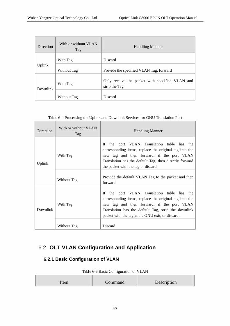
Wuhan Yangtze Optical Technology Co., Ltd. OpticalLink C8000 EPON OLT Operation Manual
53
Table 6-4 Processing the Uplink and Downlink Services for ONU Translation Port
Direction With or without VLAN
Tag Handling Manner
Uplink
With Tag
If the port VLAN Translation table has the corresponding items, replace the original tag into the new tag and then forward; if the port VLAN Translation has the default Tag, then directly forward the packet with the tag or discard
Without Tag Provide the default VLAN Tag to the packet and then forward
Downlink With Tag
If the port VLAN Translation table has the corresponding items, replace the original tag into the new tag and then forward; if the port VLAN Translation has the default Tag, strip the downlink packet with the tag at the ONU exit, or discard.
Without Tag Discard
6.2 OLT VLAN Configuration and Application
6.2.1 Basic Configuration of VLAN
Table 6-6 Basic Configuration of VLAN
Item Command Description
Direction With or without VLAN
Tag Handling Manner
Uplink With Tag Discard
Without Tag Provide the specified VLAN Tag, forward
Downlink With Tag
Only receive the packet with specified VLAN and strip the Tag
Without Tag Discard

Wuhan Yangtze Optical Technology Co., Ltd. OpticalLink C8000 EPON OLT Operation Manual
54
Enter config view config terminal -
Create VLAN and enter the VLAN view.
vlan vlan-id
vlanfirst-id [last-id]
no vlan first-id [last-id]
The numeric area of vlan-id and first-id is 1 ~ 4094
The numeric area of last-id is 2 ~ 4094
Specify the description information of current VLAN
description desc
Mandatory
By default, the description information of the VLAN is the VLAN ID of the VLAN
Set the global VLAN mode 802.1ad (enable|disable)
Mandatory (any a mode)
For setting the vlan mode of the system, if in the 802.1ad enable and it works in the vlan stack mode, the port can be set as the transparent or hybrid mode and enable modify vlan, nested vlan; otherwise, the system can work in the ordinary 802.1q vlan mode. Note the command is the global command, which is set initially preferably.
6.2.2 VLAN Multicast Forwarding Configuration
The following commands can be used for the setup of the forwarding ways of the Multicast packets in the VLAN.
There are three forwarding ways in the VLAN for the Multicast packet:
Way 1: if there is a multicast packet, broadcast to the ports of all VLANs.
Way 2: after receiving the Multicast packets, search the address table, if the matched item is found, then forward to the port of the Multicast group of the current VLAN;

Wuhan Yangtze Optical Technology Co., Ltd. OpticalLink C8000 EPON OLT Operation Manual
55
otherwise, broadcast in the VLAN.
Way 3: after receiving the Multicast packets, search the address table, if the matched item is found, then forward to the port of the Multicast group of the current VLAN; otherwise, discard.
Table 6-7 Setup of the VLAN Multicast Forwarding Ways
Item Command Description
Enter config View config terminal -
Enter VLAN View vlan vlan-id -
Set the multicast packet forwarding ways in the VLAN
mcast-flood (all|unknown|none) Mandatory
6.2.3 802.1Q-based CVLAN Hybrid Application
Effects: for the untagged (tpid does not equal to TPID set (global inner-tpid), regarded as the untagged packet) or the prio-tag packet, mark with the PVID and default priority, as well as TPID (inner-tpid) and then participate into forwarding; for the single tagged package, its forwarding must be determined in accordance with the VLAN member table and then the stripping of the VLAN tag is determined in accordance with the untagged bitmap in the exit of the port.
When the global switch is in the 802.1ad disable state, then all ports automatically work in the 802.1Q QVLAN Hybrid model. PVID, default Priority, VLAN members table (global) and VLAN untagged bitmap are configurable.
6.2.3.1 Hybrid Port-based CVLAN Configuration
Hybrid port allows the passing of multiple VLANs, for the detailed processing way of the packet, see section 6.1.2.1.1.
Table 6-8 Hybrid Port-based CVLAN Configuration
Item Command Description
Enter config view config terminal -

Wuhan Yangtze Optical Technology Co., Ltd. OpticalLink C8000 EPON OLT Operation Manual
56
Configure the global VLAN model
802.1ad disable Mandatory (or 802.1Q mode)
Enter port view
interface gigabit-ethernet interface-num
interface pon interface-num
interface x-ethernet (xe1|xe2|xe3)
-
Configure the port VLAN type
port type hybrid Mandatory (hybrid by default)
Allow / Remove the specified VLAN to pass through the current hybrid port
port vlan vlan-id (tagged|untagged)
no port vlan vlan-id
Mandatory
By default, all hybrid ports only allow the passing through of VLAN1
At the same time, specify the current hybrid port to add multiple VLANs
port vlan vlan-id-from to vlan-id-end (tagged | untagged)
no port vlan vlan-id-from to vlan-id-end
Optional
Configure the default VLAN ID of the port
port pvid vlan-id Optional
Display the port VLAN configuration
show port vlan
Optional
For inspecting the configuration
Note:
Before setting the specified VLAN to pass through the hybrid port, the VLAN that is allowed to pass through must already exist.

Wuhan Yangtze Optical Technology Co., Ltd. OpticalLink C8000 EPON OLT Operation Manual
57
The default VLAN ID of the hybrid port of the device of the terminal must be the same to the default VLAN ID of the hybrid port of the devie of the opposite terminal, or the packet cannot be correctly transmitted.
6.2.3.2 Example of the Typical Configuration for Hybrid Port-based CVLAN
6.2.3.2.1 Network Requirement
Create VLAN10 and VLAN20, and specify the information of the former as the Dept R&D and the latter as the Dept Finac.
Configure PON port 3/1 to the VLAN10 and set the exit mode to the tagged mode; add the PON port 3/4 to VLAN20 and set the exit mode to the untagged mode and the port PVID to 20; Configure the Service Network Interface 9/1 to VLAN10 and VLAN20, and set both exit modes to the tagged mode.
6.2.3.2.2 Network Diagram
Figure 6-5 Hybrid Port-based CVLAN
6.2.3.2.3 Configuration Procedure
$ Configure the global VLAN mode to be 802.1Q
C8000#config terminal
C8000(config)#802.1ad disable
C8000(config)# sho 802.1ad
system vlan mode is: 802.1q
$ Create VLAN10

Wuhan Yangtze Optical Technology Co., Ltd. OpticalLink C8000 EPON OLT Operation Manual
58
C8000#config terminal
C8000(config)# vlan 10
C8000(config-vlan-10)# description Dept R&D
C8000(config-vlan-10)# quit
$ Create VLAN20
C8000(config)# vlan 20
C8000(config-vlan-20)# description Dept Finac
C8000(config-vlan-20)# quit
$ Configure the PON port 3/1 to be hybrid port; add VLAN10 and set the exit mode to the tagged mode
C8000(config)# interface pon 3/1
C8000(config-if-pon-3/1)#port type hybrid
C8000(config-if-pon-3/1)#port vlan 10 tagged
$ Configure the PON port 3/4 to be hybrid port; add VLAN20 and set the exit mode to the tagged mode and PVID to 20
C8000(config)# interface pon 3/4
C8000(config-if-pon-3/4)#port type hybrid
C8000(config-if-pon-3/4)#port vlan 20 untagged
C8000(config-if-pon-3/4)#port pvid 20
$ Configure the service network interface 9/1 to be hybrid port; add VLAN 10 and 20, and set the exit mode to the tagged mode
C8000(config)# interface gigabit-ethernet 9/1
C8000(config-if-gigabit-ethernet-9/1)#port type hybrid
C8000(config-if-gigabit-ethernet-9/1)#port vlan 10 tagged
C8000(config-if-gigabit-ethernet-9/1)#port vlan 20 tagged

Wuhan Yangtze Optical Technology Co., Ltd. OpticalLink C8000 EPON OLT Operation Manual
59
6.2.4 802.1ad-based SVLAN Hybrid Application
Effects: similar to the above application, but not all non-SVLAN-Tags (S-Tag refers to the one that the outer tpid is equivalent to the template value of the specified outter-tpid) are processed as the untagged packet.
When the global switch is in the 802.1ad enable state, then set the property of the port in pairs working in the hybrid mode to be hybrid. For the hybrid port of the type, the outer-tpid, PVID, default Priority, VLAN member table (global) and VLAN untagged bitmap are configurable.
6.2.4.1 Hybrid Port-based SVLAN Configuration
Table 6-9 Hybrid Port-based SVLAN Configuration
Item Command Description
Enter config View config terminal -
Configure the global VLAN model
802.1ad enable Mandatory
Enter port View
interface gigabit-ethernet interface-num
interface pon interface-num
interface x-ethernet (xe1|xe2|xe3)
-
Configure the port VLAN type
port type hybrid Mandatory
Allow / Remove the specified VLAN to pass through the current hybrid port
port vlan vlan-id (tagged|untagged)
no port vlan vlan-id
Mandatory
By default, all hybrid ports only allow the passing through of VLAN1
At the same time, specify the current hybrid port to add
port vlan vlan-id-from to vlan-id-end (tagged | untagged)
Optional

Wuhan Yangtze Optical Technology Co., Ltd. OpticalLink C8000 EPON OLT Operation Manual
60
multiple VLANs no port vlan vlan-id-from to vlan-id-end
Configure/restore the default outer_tpid of the port
port outer_tpid tpid-index
no port outer_tpid Mandatory
Configure the default VLAN ID of the port
port pvid vlan-id Mandatory
Configure/restore the default priorityof the port
priority (<0-7>|original)
no priority
Mandatory
The default priority of the port is 0
Display the port VLAN configuration
show port vlan
Optional
For inspecting the configuration
Note:
Before setting the specified VLAN to pass through the hybrid port, the VLAN that is allowed to pass through must already exist.
The default VLAN ID of the hybrid port of the device of the terminal must be the same to the default VLAN ID of the hybrid port of the devie of the opposite terminal, or the packet cannot be correctly transmitted.
6.2.4.2 Example of the Typical Configuration for Hybrid Port-based SVLAN
6.2.4.2.1 Network Requirement
Create VLAN10 and VLAN20, and specify the information of the former as the Dept R&D and the latter as the Dept Finac.
Configure PON port 3/1 to the VLAN10 and set the exit mode to the tagged mode; set the portouter_tpid to Index3 0x88a8 and portprio to 5; add the PON port 3/4 to

Wuhan Yangtze Optical Technology Co., Ltd. OpticalLink C8000 EPON OLT Operation Manual
61
VLAN20 and set the exit mode to the untagged mode; set portouter_tpid to Index3 0x88a8 and portprio to 6, as well as portPVID to 20; Configure the Service Network Interface 9/1 to VLAN10 and VLAN20, and set the exit mode to the tagged mode and portouter_tpid to Index3 0x88a8 and portprio to 7.
6.2.4.2.2 Network Diagram
Figure 6-6 Hybrid Port-based SLVAN
6.2.4.2.3 Configuration Procedure
$ Configure the global VLAN mode to be 802.1ad
C8000#config terminal
C8000(config)#802.1ad enable
C8000(config)# sho 802.1ad
system vlan mode is: 802.1ad
$Create VLAN10
C8000#config terminal
C8000(config)# vlan 10
C8000(config-vlan-10)# description Dept R&D
C8000(config-vlan-10)# quit
$Create VLAN20
C8000(config)# vlan 20
C8000(config-vlan-20)# description Dept Finac

Wuhan Yangtze Optical Technology Co., Ltd. OpticalLink C8000 EPON OLT Operation Manual
62
C8000(config-vlan-20)# quit
$ Configure the PON port 3/1 to be hybrid port; add VLAN10 and set the exit mode to the tagged mode
C8000(config)# interface pon 3/1
C8000(config-if-pon-3/1)#port type hybrid
C8000(config-if-pon-3/1)#port vlan 10 tagged
C8000(config-if-pon-3/1)# port outer_tpid 3
C8000(config-if-pon-3/1)#priority 5
$ Configure the PON port 3/4 to be hybrid port; add VLAN20 and set the exit mode to the tagged mode and PVID to 20
C8000(config)# interface pon 3/4
C8000(config-if-pon-3/4)#port type hybrid
C8000(config-if-pon-3/4)#port vlan 20 untagged
C8000(config-if-pon-3/1)# port outer_tpid 3
C8000(config-if-pon-3/1)#priority 6
C8000(config-if-pon-3/4)#port pvid 20
$ Configure the service network interface 9/1 to be hybrid port; add VLAN 10 and 20, and set the exit mode to the tagged mode
C8000(config)# interface gigabit-ethernet 9/1
C8000(config-if-gigabit-ethernet-9/1)#port type hybrid
C8000(config-if-gigabit-ethernet-9/1)#port vlan 10 tagged
C8000(config-if-gigabit-ethernet-9/1)#port vlan 20 tagged
C8000(config-if-pon-3/1)# port outer_tpid 3
C8000(config-if-pon-3/1)#priority 7

Wuhan Yangtze Optical Technology Co., Ltd. OpticalLink C8000 EPON OLT Operation Manual
63
6.2.5 VLAN Transparent Application
Transparent Application: the port receives and sends any packets, regardless of whether the VLAN Tag is provided or not, what kind of VLAN Tag it is, that is the transparent transmission of packet.
VLAN-VPN is a simple and flexible, two-layer VPN tunnel technology. It is to encapsulate the outer-layer VLAN tag for the private network packet of the users by the operator’s access terminal, so as to ensure the packet carries two-layer VLAN tag when it passes through the backbone network (Public Network) of the operator. In the public network, the packet can be transmitted in accordance with the out-layer VLAN Tag (or VLAN Tag of the public network), then the VLAN Tag of the user's private network is transmitted as the data in the packet.
Effects: a. Completely transparent transmission, ingress/egress from the transparent port and egress/ ingress from the hybrid port, that is, realize the ingress/egress of any packet in the original state. b. VLAN VPN, egress/ingress from transparent port, egress/ingress from hybrid port and the egress/ingress of any packet in the original form (The svlan tag is not stripped in the hybrid port).
When the global switch is in the 802.1ad enable state, set PON port to work in the transparent mode and the service network interface to work in the hybird mode (based on 802.1ad). For the hybrid port, the outer-tpid, PVID, default Priority, VLAN member table (global) and VLAN untagged bitmap are configurable. For transparent port, the outer-tpid, PVID, default Priority, VLAN member table (global) and VLAN untagged bitmap are configurable.
The configuration must be made by default, the application, due to the absence of the ingress VLAN translation table, all packets must allow the transparent transmission. If some of the packets cannot be subject to the transparent transmission (CVLAN adds to SVLAN or CVLAN changes to SVLAN), the ingress VLAN translation table can be configured, in case of 1:1 VLAN translation, it needs to automatically configure the egress VLAN translation table reversely based on the ingress VLAN translation table. In case of the VLAN-based VPN (with the exit of SVLAN, no stripped), then the exit hybrid port can be provided with the tag. Note: the ports of both sides belong to the same SVLAN.
6.2.5.1 VLAN Transparent Transmission Configuration
Table 6-10 VLAN Transparent Transmission

Wuhan Yangtze Optical Technology Co., Ltd. OpticalLink C8000 EPON OLT Operation Manual
64
Item Command Description
Enter config View config terminal -
Configure the global VLAN model
802.1ad enable Mandatory
Enter OLTport View
interface gigabit-ethernet interface-num
interface pon interface-num
interface x-ethernet (xe1|xe2|xe3)
-
Configure the port VLAN type
port type hybrid|transparent
Mandatory
Service Network Interfacehybrid ; PON口 transparent。
Configure portouter_tpid
port outer_tpid <1-4> Optional
Configure portpriority
priority <0-7> Optional
Configure the default VLAN ID of the port
port pvid vlan-id Optional
Allow the default VLAN to pass through the current port
port vlan vlan-id untagged|tagged
Optional
The uplink exit mode must be untagged and the PON port is tagged.
Display the port VLAN configuration
show port vlan
Optional
For inspecting the configuration

Wuhan Yangtze Optical Technology Co., Ltd. OpticalLink C8000 EPON OLT Operation Manual
65
Note:
Before configuring the default VLAN ID, the VLAN must already exist.
The transparent port must be added to the VLAN corresponding to the default VLAN.
6.2.5.2 VLAN Transparent Transmission Configuration Example
6.2.5.2.1 Network Requirement
Realize the transparent transmission of packet between PON port 3/1 and Service Network Interface 9/1. The service network interface of hybrid type exits in the VLAN of the PON port pvid by the untagged mode; the PON port in the transparent mode is not configured with any forwarding entries, even when the forwarding entries are configured, if it wants to realize the transparent transmission of packets, ensuring the packet not in the forwarding entries, that is to say, the packet can be directly forwarded in the manner when the packet is transmitted. For the downlink direction, when the packet passes through the unlink hybrid, the SVLAN will be marked with and when passing through the PON port transparent, the outer SVLAN will be stripped (The transparent transmission of the downlink direction will strip the outer-layer SVLAN and the inner-layer CVLAN is left, if the data packets are with only one-layer TAG, after they pass through the uplink hybrid and PON port transparent, the data packets without TAG cannot be received).
Create VLAN 200
PON Port Configuration: 802.1ad transparent mode, pvid 200, adding VLAN 200 in the untagged;
Service Network Interface Configuration: 802.1ad hybrid mode, pvid 1, adding VLAN 200 in the untagged mode.
[Note] In the above networking, if the PON port pvid is 1, the creation of any VLAN is not needed(For the Service Network Interface and the PON port, adding to any other VLANs is not needed, because they are in the default VLAN 1.)

Wuhan Yangtze Optical Technology Co., Ltd. OpticalLink C8000 EPON OLT Operation Manual
66
6.2.5.2.2 Network Diagram
Figure 6-7 VLAN Transparent Transmission Example
6.2.5.2.3 Configuration Procedure
$Create VLAN200
C8000#config terminal
C8000(config)# vlan 2000
C8000(config-vlan-2000)# quit
$ Configure the PON port3/1 into the transparent port.
C8000(config)# interface pon 3/1
C8000(config-if-pon-3/1)#port type transparent
C8000(config-if-pon-3/1)#port pvid 200
$ Configure the Service Network Interface 9/1 into the hybrid(under the 802.1ad)port.
C8000(config)# interface gigabit-ethernet 9/1
C8000(config-if-gigabit-ethernet-9/1)#port type hybrid
C8000(config-if-gigabit-ethernet-9/1)# port vlan 200 untagged
6.2.6 VLAN Translate Application
Translation Application: applicable to the occasion when the Tag provided by the user network cannot be trusted by the network of service provider on the premise that when one side of the C8000 is connected with the user network and the other side is connected with the network of service provider. The port connecting the user network translates the

Wuhan Yangtze Optical Technology Co., Ltd. OpticalLink C8000 EPON OLT Operation Manual
67
tag of the user network in the uplink data into the VLAN Tag trusted by the network of service provider or the port connecting the network of service provider translates the VLAN Tag in the downlink data into the tag of user network.
When the global switch is in the 802.1ad enable state, set PON port to work in the transparent mode and the service network interface to work in the hybird mode (based on 802.1ad). For the hybrid port, the outer-tpid, PVID, default Priority, VLAN member table (global) and VLAN untagged bitmap are configurable. For transparent port, the outer-tpid, PVID, default Priority, VLAN member table (global), VLAN untagged bitmap and VLAN translate mode are configurable. Note: the ports of both sides belong to the same SVLAN.
1:1 VLAN Translation
Effects: ingress from the transparent port and egress from the hybrid port; the different CVLANs in the ingress VLAN translation table at the uplink direction can be translated into the different SVLANs in accordance with the items of the translation table. The different CVLANs in the egress vlan translation table at the downlink direction can be translated into the required CVLAN by the application of the SVLAN index and in accordance with the items of the translation table. The original priority can be modified or retained.
Set the transparent port to 1:1 translation, and add the mapping table to be translated into the ingress VLAN translation table, the original priority can be modified or retained. Automatically add the corresponding ingress reverse mapping table into the background egress VLAN translation table and apply the processing strategy of the same priority.
6.2.6.1 VLAN Translation Configuration
The translation port is used for realizing the translation between the tag of user’s network and the tag of the network of service providers.
Table 6-11 VLAN Translation
Item Command Description
Enter config View config terminal -
Configure the global VLAN model
802.1ad enable Mandatory
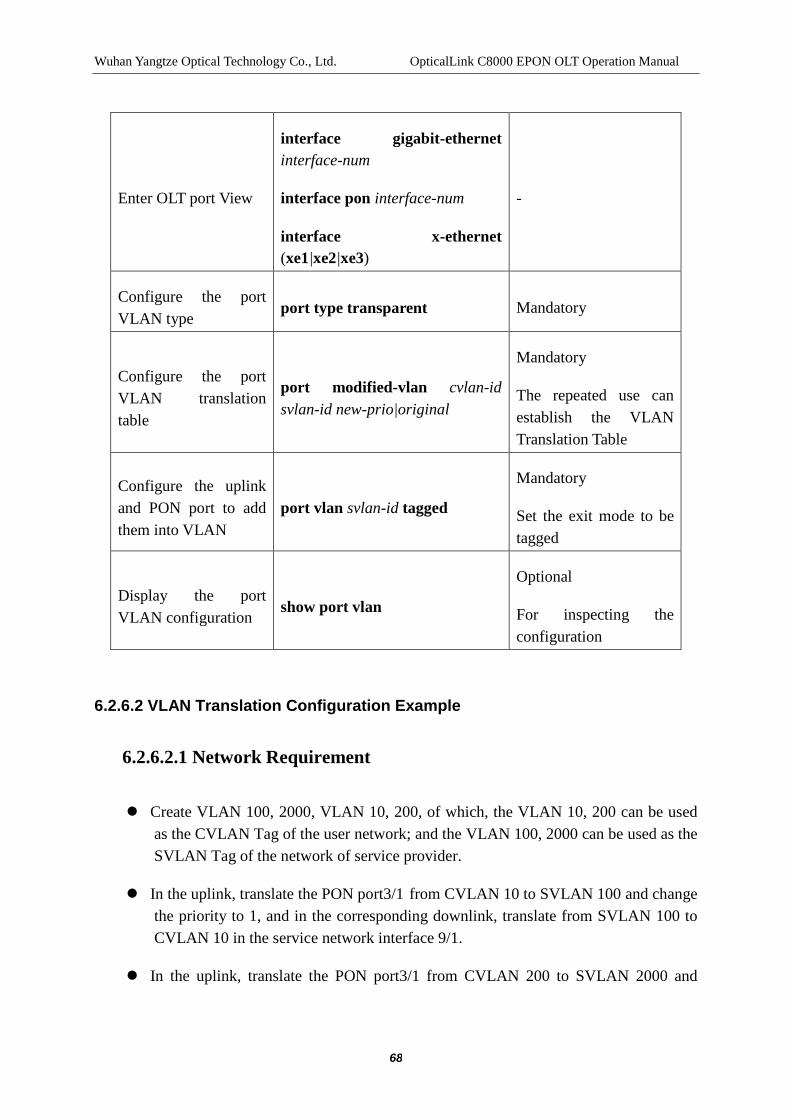
Wuhan Yangtze Optical Technology Co., Ltd. OpticalLink C8000 EPON OLT Operation Manual
68
Enter OLT port View
interface gigabit-ethernet interface-num
interface pon interface-num
interface x-ethernet (xe1|xe2|xe3)
-
Configure the port VLAN type
port type transparent Mandatory
Configure the port VLAN translation table
port modified-vlan cvlan-id svlan-id new-prio|original
Mandatory
The repeated use can establish the VLAN Translation Table
Configure the uplink and PON port to add them into VLAN
port vlan svlan-id tagged
Mandatory
Set the exit mode to be tagged
Display the port VLAN configuration
show port vlan
Optional
For inspecting the configuration
6.2.6.2 VLAN Translation Configuration Example
6.2.6.2.1 Network Requirement
Create VLAN 100, 2000, VLAN 10, 200, of which, the VLAN 10, 200 can be used as the CVLAN Tag of the user network; and the VLAN 100, 2000 can be used as the SVLAN Tag of the network of service provider.
In the uplink, translate the PON port3/1 from CVLAN 10 to SVLAN 100 and change the priority to 1, and in the corresponding downlink, translate from SVLAN 100 to CVLAN 10 in the service network interface 9/1.
In the uplink, translate the PON port3/1 from CVLAN 200 to SVLAN 2000 and

Wuhan Yangtze Optical Technology Co., Ltd. OpticalLink C8000 EPON OLT Operation Manual
69
remain the original priority, and in the corresponding downlink, translate from the SVLAN 2000 to CVLAN 2000 in the service network interface 9/1.
[Note] The service network interface and the PON port must be added into the SVLAN, if all are added into the SVLAN in the tagged mode, the packets with tags can only be received at the downlink and uplink directions; if the uplink is provided with the tagged packet and the downlink is provided with the untagged packet, the packets without tags can only be received at the downlink direction and the packets without tags can only be received at the uplink direction; if the uplink is provided with the untagged packets and the downlink is provided with the tagged packets, the packets without tags can only be received at the uplink direction and the packets without tags can only be received at the downlink direction.
6.2.6.2.2 Network Diagram
Figure 6-8 VLAN Translation Example
6.2.6.2.3 Configuration Procedure
$Create VLAN200
C8000#config terminal
C8000(config)# vlan 200
C8000(config-vlan-200)# quit
$Create VLAN2000
C8000#config terminal
C8000(config)# vlan 2000

Wuhan Yangtze Optical Technology Co., Ltd. OpticalLink C8000 EPON OLT Operation Manual
70
C8000(config-vlan-2000)# quit
$Create VLAN10
C8000#config terminal
C8000(config)# vlan 10
C8000(config-vlan-10)# quit
$Create VLAN100
C8000#config terminal
C8000(config)# vlan 100
C8000(config-vlan-100)# quit
$ Configure the PON port 3/1 into the transparent port and implement the 200->2000 translation, and keep the original priority
C8000(config)# interface pon 3/1
C8000(config-if-pon-3/1)#port type transparent
C8000(config-if-pon-3/1)#port modified-vlan 200 2000 original
C8000(config-if-pon-3/1)#port vlan 2000 tagged
$ Configure the PON port 3/1 into the transparent port and implement the10->1000, change the priority to 1
C8000(config)# interface pon 3/1
C8000(config-if-pon-3/4)#port type transparent
C8000(config-if-pon-3/4)#port modified-vlan 10 100 1
C8000(config-if-pon-3/4)#port vlan 100 tagged
$ Configure the Service Network Interface 9/1 into the hybrid port, implement the 2000->200 and 100->10 translation, and keep the original priority
C8000(config)# interface gigabit-ethernet 9/1
C8000(config-if-gigabit-ethernet-9/1)#port type hybrid

Wuhan Yangtze Optical Technology Co., Ltd. OpticalLink C8000 EPON OLT Operation Manual
71
C8000(config-if-gigabit-ethernet-9/1)#port vlan 2000 tagged
C8000(config-if-gigabit-ethernet-9/1)#port vlan 100 tagged
6.2.7 VLAN QinQ Application
QinQ type: applicable to the occasion when the network of service provider uses the SVLAN Tag to differentiate services and the user network uses the CVLAN Tag to differentiate users on the premise that that one side of the C8000 is connected with user network and the other side is connected with network of service provider. At that time, the port connecting the user network needs to be set into the transparent mode and configure the nested table, for the unlink data packet, add the SVLAN tag of the network of service provider to the outer layer of the CVLAN Tag of user network; for the downlink packet, strip the SVLAN Tag of the outer layer and then forward to the user network.
When the global switch is in the 802.1ad enable state, set PON port to work in the transparent mode and the service network interface to work in the hybird mode (based on 802.1ad). For the hybrid port, the outer-tpid, PVID, default Priority, VLAN member table (global) and VLAN untagged bitmap are configurable. For transparent port, the outer-tpid, PVID, default Priority, VLAN member table (global) and VLAN untagged bitmap are configurable. More attention must be paid to the above default configuration and the configuration of the VLAN translation table. To meet the requirements of the application, it needs to not to strip the VLAN tag of the SVLAN at the hybrid port, and it needs to strip the SVLAN(un-tag) at the opposite transparent port. Note: the ports of both sides belong to the same SVLAN.
Effects: ingress from the transparent port and egress from the hybrid port; in the ingress VLAN translation table, the different CVLANs can add different SVLANs in accordance with the items of the translation table. The priority can modify or use the default priority of the port.
6.2.7.1 VLAN Stacking Configuration
The QinQ port allows adding the SVLAN Tag of the service provider networks to the outer layer of the user-network CVLAN Tag.
Table 6-12 VLAN Translation
Item Command Description
Enter config View config terminal -

Wuhan Yangtze Optical Technology Co., Ltd. OpticalLink C8000 EPON OLT Operation Manual
72
Configure the global VLAN model
802.1ad enable Mandatory
Enter OLTport View
interface gigabit-ethernet interface-num
interface pon interface-num
interface x-ethernet (xe1|xe2|xe3)
-
Configure the port VLAN type
port type transparent Mandatory
Configure the port VLAN translation table
port nested-vlan cvlan-id svlan-id svlan-prio
Mandatory
The repeated use can establish the VLAN nested table
Configure the service network interface, allowing the passing of svlan-id
port vlan svlan-id tagged
Mandatory
Set the exit mode to be tagged
Configure the PON port, allowing the passing of svlan-id
port vlan svlan-id untagged
Mandatory
Set the exit mode to be untagged
Display the port VLAN configuration
show port vlan
Optional
For inspecting the configuration
Note:
In the QinQ applications, the transparent port and the hybrid port are appeared in pairs to ensure the service data at both directions can be forwarded normally.

Wuhan Yangtze Optical Technology Co., Ltd. OpticalLink C8000 EPON OLT Operation Manual
73
6.2.7.2 VLAN Stacking Configuration Example
6.2.7.2.1 Network Requirement
Create VLAN 200, 300, VLAN2, of which, the VLAN 200, 300 are used as the CVLAN Tag of the user network for distinguishing users; the VLAN2 is used as the SVLAN Tag of the network of service provider for identifying data services.
On PON port 3/1, for the uplink data, add the SVLAN 2 to the outer layer of the CVLAN 200 and translate the priority to 5; for the downlink data, strip the SVLAN.
On PON port 3/1, for the uplink data, add the SVLAN 2 to the outer layer of the CVLAN300 and use the default priority (Port priority of the transparent port); for the downlink data, strip the SVLAN.
6.2.7.2.2 Network Diagram
Figure 6-9 VLAN Stacking Example
6.2.7.2.3 Configuration Procedure
$Create VLAN100
C8000#config terminal
C8000(config)# vlan 200
C8000(config-vlan-200)# quit
$Create VLAN300
C8000#config terminal

Wuhan Yangtze Optical Technology Co., Ltd. OpticalLink C8000 EPON OLT Operation Manual
74
C8000(config)# vlan 300
C8000(config-vlan-300)# quit
$Create VLAN2
C8000#config terminal
C8000(config)# vlan 2
C8000(config-vlan-2)# quit
$ Configure the PON port 3/1into the transparent mode and the nested table items to add the SVLAN2 to the outer layer of the CVLAN100, the priority of 5;
C8000(config)# interface pon 3/1
C8000(config-if-pon-3/1)#port type transparent
C8000(config-if-pon-3/1)#port nested-vlan 100 2 5
C8000(config-if-pon-3/1)#port vlan 2 untagged
$ Configure the PON port 3/4into the transparent mode and add the SVLAN2 to the outer layer of the CVLAN200, the priority by default (that is, the value of the priority of PON port)
C8000(config)# interface pon 3/4
C8000(config-if-pon-3/4)#port type transparent
C8000(config-if-pon-3/4)#port nested-vlan 200 2 2
C8000(config-if-pon-3/4)#port vlan 2 untagged
$ Configure Service Network Interface 9/1 to the hybrid port
C8000(config)# interface gigabit-ethernet 9/1
C8000(config-if-gigabit-ethernet-9/1)#port type hybrid
C8000(config-if-gigabit-ethernet-9/1)#port vlan 2 tagged

Wuhan Yangtze Optical Technology Co., Ltd. OpticalLink C8000 EPON OLT Operation Manual
75
6.3 ONU VLAN Configuration
6.3.1 VLAN Transparent Transmission
6.3.1.1 VLAN Transparent Transmission Configuration
Table 6-13 Configuring the Port VLAN Mode of ONU to be Transparent Mode
Item Command Description
Enter config View config terminal -
Configure the global VLAN model
802.1ad disable Optional
Enter onu View interface onu interface-num Mandatory
interface-num refers to the ONU number
Configure port VLAN mode to be transparent mode
port vlan (uniid | all) transparent Mandatory
Display the port VLAN configuration
show port vlan (uniid | all) Optional
For inspecting the configuration
Note:
The default VLAN configuration of the ONU port is transparent.
6.3.1.2 VLAN Transparent Transmission Configuration Example
6.3.1.2.1 Network Requirement
Connect the user PC2 with the layer 2 switch connected with the ONU3/1:1.
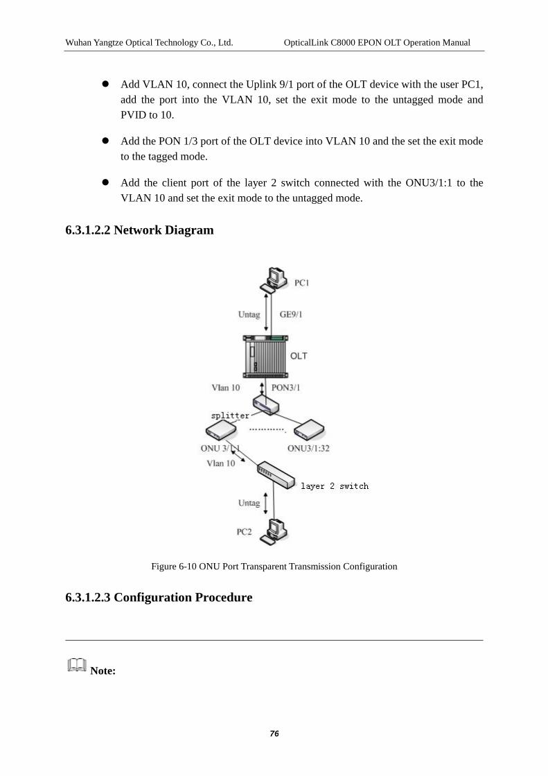
Wuhan Yangtze Optical Technology Co., Ltd. OpticalLink C8000 EPON OLT Operation Manual
76
Add VLAN 10, connect the Uplink 9/1 port of the OLT device with the user PC1, add the port into the VLAN 10, set the exit mode to the untagged mode and PVID to 10.
Add the PON 1/3 port of the OLT device into VLAN 10 and the set the exit mode to the tagged mode.
Add the client port of the layer 2 switch connected with the ONU3/1:1 to the VLAN 10 and set the exit mode to the untagged mode.
6.3.1.2.2 Network Diagram
Figure 6-10 ONU Port Transparent Transmission Configuration
6.3.1.2.3 Configuration Procedure
Note:

Wuhan Yangtze Optical Technology Co., Ltd. OpticalLink C8000 EPON OLT Operation Manual
77
In the following all configuration examples, it is assumed that the ONU has been registered and are bound, no more explanation is made in the following part.
$ Create VLAN10
C8000#config terminal
C8000(config)# vlan 10
C8000(config-vlan-10)# quit
$ Add the Uplink port 9/1 into the VLAN10 and set the exit mode to the untagged mode and the PVID to 10.
C8000(config)# interface gigabit-ethernet 9/1
C8000(config-if-gigabit-ethernet-9/1)#port vlan 10 untagged
C8000(config-if-gigabit-ethernet-9/1)#port pvid 10
$ Add the PON port 3/1 into the VLAN10 and set the exit mode to the tagged mode
C8000(config)# interface pon 3/1
C8000(config-if-pon-3/1)#port vlan 10 tagged
6.3.2 VLAN Tag
6.3.2.1 VLAN Tag Configuration
Table 6-14 Configuring the port VLAN mode of ONU to be tag mode
Item Command Description
Enter config View
config terminal -
Configure the global VLAN model
802.1ad disable Optional

Wuhan Yangtze Optical Technology Co., Ltd. OpticalLink C8000 EPON OLT Operation Manual
78
Enter onu View interface onu interface-num
Mandatory
interface-num refers to the ONU number
Configure the port VLAN mode to tag
port vlan (uniid | all) tag TPID pri vlan-id
Mandatory
TPID: the tpid with tag.
pri: the priority with tag.
vlan-id: the vlan-id with tag.
Display the port VLAN configuration
show port vlan (uniid | all)
Optional
For inspecting the configuration
6.3.2.2 VLAN Tag Example
6.3.2.2.1 Network Requirement
Connect the ONU3/1:1 with the user PC2
Add VLAN 10, connect the Uplink 9/1 port of the OLT device with the user PC1 and add the port into the VLAN 10, set the exit mode to the untagged mode and PVID to 10.
Add the PON 3/1 port of the OLT device into VLAN 10 and set the exit mode to the tagged mode.
Configure the VLAN of the port connecting the ONU3/1:1 with the PC2 into the tag mode; set the TPID to 8100, vid to 10 and the priority to 0.

Wuhan Yangtze Optical Technology Co., Ltd. OpticalLink C8000 EPON OLT Operation Manual
79
6.3.2.2.2 Network Diagram
Figure 6-11 ONU Port Tag Configuration
6.3.2.2.3 Configuration Procedure
$Create VLAN10
C8000#config terminal
C8000(config)# vlan 10
C8000(config-vlan-10)# quit
$ Add uplink port 9/1 to VLAN10 and set the exit mode to untagged and PVID to 10
C8000(config)# interface gigabit-ethernet 9/1
C8000(config-if-gigabit-ethernet-9/1)#port vlan 10 untagged
C8000(config-if-gigabit-ethernet-9/1)#port pvid 10

Wuhan Yangtze Optical Technology Co., Ltd. OpticalLink C8000 EPON OLT Operation Manual
80
$ Add PON port 3/1 to VLAN10 and set the exit mode to tagged
C8000(config)# interface pon 3/1
C8000(config-if-pon-3/1)#port vlan 10 tagged
$ Configure the port1 of ONU3/1:1 to tag and set TPID to 8100, priority to 0 and vid to 10.
C8000(config-if-onu-3/1:1)#port vlan 1 tag 8100 0 10
6.3.3 VLAN Translation
6.3.3.1 VLAN Translation Configuration
Table 6-15 Configuring the port VLAN model of ONU to translation mode
Item Command Description
Enter config View config terminal -
Configure the global VLAN model
802.1ad disable Optional
Enter onu View interface onu interface-num
Mandatory
interface-num refers to the ONU number
Configure the port VLAN mode to be default translation configuration
port vlan (uniid | all) translation
Mandatory
Configure the port VLAN translation mode to be default tag
port vlan (uniid| all) translation default-tag def-tpid def-pri def-vid
Mandatory
def-tpid:tpid with default tag
def-pri : priority with default tag
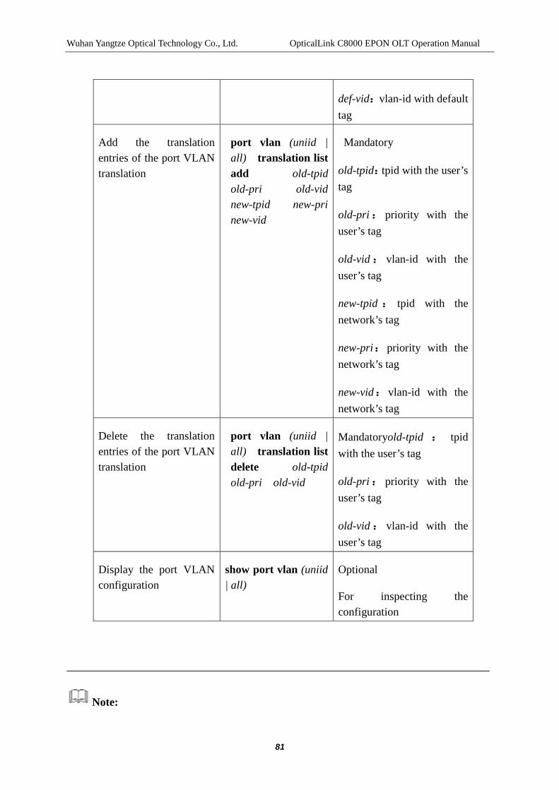
Wuhan Yangtze Optical Technology Co., Ltd. OpticalLink C8000 EPON OLT Operation Manual
81
def-vid:vlan-id with default tag
Add the translation entries of the port VLAN translation
port vlan (uniid | all) translation list add old-tpid old-pri old-vid new-tpid new-pri new-vid
Mandatory
old-tpid:tpid with the user’s tag
old-pri: priority with the user’s tag
old-vid : vlan-id with the user’s tag
new-tpid : tpid with the network’s tag
new-pri:priority with the network’s tag
new-vid:vlan-id with the network’s tag
Delete the translation entries of the port VLAN translation
port vlan (uniid | all) translation list delete old-tpid old-pri old-vid
Mandatoryold-tpid : tpid with the user’s tag
old-pri: priority with the user’s tag
old-vid : vlan-id with the user’s tag
Display the port VLAN configuration
show port vlan (uniid | all)
Optional
For inspecting the configuration
Note:

Wuhan Yangtze Optical Technology Co., Ltd. OpticalLink C8000 EPON OLT Operation Manual
82
In the translation mode, the ONU port cannot translate a number of different vids into a vid, and translate a vid into a number of different vids, either. The maximum number of the translation entries is 7.
6.3.3.2 VLAN translation Example
6.3.3.2.1 Network Requirement
Connect user PC3 and PC4 with the layer 2 switch connected to the ONU3/1:1.
Add VLAN 10; connect the Uplink 9/1 port of the OLT device with the user PC1; add the port to VLAN 10; and set the exit mode to the untagged mode and PVID to 10.
Add VLAN 20; connect the Uplink 9/2 port of the OLT device with the user PC2; add the port to VLAN 20; and set the exit mode to the untagged mode and PVID to 20.
Add PON 3/1 port of the OLT device to VLAN 10, 20 and set the exit mode to the tagged mode.
Configure the VLAN of the port connecting the ONU3/1:1and the layer 2 switch to be translation mode; configure two translation entries, respectively switching 101 to 10 and 102 to 20.
Connect the user’s port of the two-layer switch connected with the ONU3/1:1 to the PC3; add to the VLAN 101; connect with PC4 and add to the VLAN 102; set the exit mode to the untagged mode; add the Service Network Interface of the switch to VLAN101, 102 and set the exit mode to the tagged mode.

Wuhan Yangtze Optical Technology Co., Ltd. OpticalLink C8000 EPON OLT Operation Manual
83
6.3.3.2.2 Network Diagram
Figure 6-12 ONU Port Translation Configuration
6.3.3.2.3 Configuration Procedure
$Create VLAN10
C8000#config terminal
C8000(config)# vlan 10
C8000(config-vlan-10)# quit
$Create VLAN20
C8000(config)# vlan 20
C8000(config-vlan-20)# quit
$ Add Uplink port 9/1 to VLAN10 and set the exit mode to the untagged mode and

Wuhan Yangtze Optical Technology Co., Ltd. OpticalLink C8000 EPON OLT Operation Manual
84
PVID to 10
C8000(config)# interface gigabit-ethernet 9/1
C8000(config-if-gigabit-ethernet-9/1)#port vlan 10 untagged
C8000(config-if-gigabit-ethernet-9/1)#port pvid 10
$ Add uplink port 9/2 to VLAN20 and set the exit mode to the untagged mode and PVID to 20
C8000(config)# interface gigabit-ethernet 9/2
C8000(config-if-gigabit-ethernet-9/2)#port vlan 20 untagged
C8000(config-if-gigabit-ethernet-9/2)#port pvid 20
$ Add PON port 3/1 to VLAN10, 20 and set the exit mode to the tagged mode
C8000(config)# interface pon 3/1
C8000(config-if-pon-3/1)#port vlan 10 tagged
C8000(config-if-pon-3/1)#port vlan 20 tagged
$ Configure the port 1 of ONU3/1:1 to be the translation mode and configure two pieces of translation entries, respectively translating 101 to 10 and 102 to 20.
C8000(config-if-onu-3/1:1)#port vlan 1 translation list add 8100 0 101 8100 0 10
C8000(config-if-onu-3/1:1)#port vlan 1 translation list add 8100 0 102 8100 0 20

Wuhan Yangtze Optical Technology Co., Ltd. OpticalLink C8000 EPON OLT Operation Manual
85
7 OLT PORT CONFIGURATION MANAGEMENT
7.1 Introduction to OLT Port Configuration
The OLT port here refers to the PON ports on all LPUs and the service network interfaces on all SCUs of the C8000 device.
The basic configuration of the OLT port includes: the setup of startup/shutdown of the port and the setup of the duplex mode and port rate, etc.
The OLT ports of the C8000 device are Gigabit Ethernet ports and the service network interfaces on the SCU can be provided with the speed and the duplex mode in a flexible way.
The Gigabit uplink electrical port only supports the 1000Mbit/s speed, it also supports the full-duplex or half duplex mode. The user can select the appropriate port speed in accordance with actual needs; however, when it is in the half-duplex mode, the speed cannot be 1000Mbit/s.
To avoid the link down of port due to the careless operation of the user, the speed and the duplex mode of the current C8000 system is fixed to the auto-negotiation (auto). The system can, in accordance with the device connected, provide the most appropriate port working mode.
The MDI/MDIX type of the port is the port jumper type, of which, the MDI refers to the Medium Dependent Interface and the MDIX refers to Medium Dependent Interface Crossover.
Figure 7-1 Connection between MDI and MDIX
Generally, the MDI port is for router and PC and MDIX port is for switch. The direct

Wuhan Yangtze Optical Technology Co., Ltd. OpticalLink C8000 EPON OLT Operation Manual
86
cable can be used to connect the MDI port and the MDIX port while the crossover cable must be used to connect two MDI ports.
7.1.1 Basic Configuration of OLT Port
In the C8000 system, the jumper type of the MDI interface is normal and the jumper type of the MDIX is across, at the same time, the C8000 system supports the self-adaption of the jumper type of ports, enabling the users free from the puzzle in the selection of the direct connection or the crossover cable. At present, the jumper type of the port is the self-adaption, so as to prevent that the port is unable to link up due to the carelessness of users.
The maximum frame length defined by the Ethernet standard is 1518 bytes, but in certain occasions, such as accelerating the file transfer, the ultra-long frame is very effective for improving the efficiency of network transmission. The maximum length of ultra-long frame supported by C8000 is 9216 bytes.
Table 7-1 Basic Configuration of OLT Port
Item Command Description
Enter config View
config terminal -
Enter OLTport View
interface gigabit-ethernet interface-num
interface pon interface-num
interface x-ethernet (xe1|xe2|xe3)
-
Enable/disable port
no shutdown/shut down
Optional
By default, port is in the enabled status
Set the description information of the port
description string
Optional
By default, the port description information is empty

Wuhan Yangtze Optical Technology Co., Ltd. OpticalLink C8000 EPON OLT Operation Manual
87
string: a length of 1-64 characters
Permit/forbid the long frame to pass through the port
jumboframe/no jumboframe
Optional
By default, the port does not allow the data frames with the length larger than 1518 bytes to pass through;
After the command is used, the data frames larger than 9216 bytes to pass through are not allowed.
7.1.2 Broadcast/ Multicast/ Unknown Unicast Storm Suppression Configuration
By the following configuration, the user can restrict the flow of certain kind that is allowed to be received by the port. When the flow exceeds the threshold set by the user, the system discards the packet over the flow limitation, thus lowering the proportion of the flow to a reasonable range and ensuring the normal operation of network services.
Table 7-2 Broadcast/ Multicast/ Unknown Unicast Storm Suppression Configuration
Item Command Description
Enter config View
config terminal -
Enter OLTport View
interface gigabit-ethernet interface-num
interface pon interface-num
interface x-ethernet (xe1|xe2|xe3)
-

Wuhan Yangtze Optical Technology Co., Ltd. OpticalLink C8000 EPON OLT Operation Manual
88
Limit the broadcast traffic that the port can receive
broadcast-suppression pps
Optional
By default, the broadcast traffic suppression does not happen to the port
Numeric area: 1-148810 for GE port and PON port; and 1-1488100 for XE port
Limit the Multicast traffic that the port can receive
multicast-suppression pps
Optional
By default, the Multicast traffic suppression does not happen to the port
Numeric area: 1-148810 for GE port and PON port; and 1-1488100 for XE port
Limit the unknown unicast traffic that the port can receive
unicast-suppression pps
Optional
By default, the unknown unicast traffic suppression does not happen to the port
Numeric area: 1-148810 for GE port and PON port; and 1-1488100 for XE port
7.1.3 Configuring the Port Flow Control Function
After the flow control function of the devices of the terminal and the opposite terminal, if the device of the terminal happens to the congestion:
When the device of the terminal sends the message to the device of the opposite terminal, it needs to inform the device of the opposite terminal to pause sending packets or slow down the sending of packets.
After the device of the opposite device receives the message, it will inform the

Wuhan Yangtze Optical Technology Co., Ltd. OpticalLink C8000 EPON OLT Operation Manual
89
device of the terminal to pause sending packets or slow down the sending of packets, thus avoiding the occurrence of the packet loss and ensuring the normal operation of network services.
Table 7-3 Configuring the Flow Control of Port
Item Command Description
Enter config View config terminal -
Enter OLTport View
interface gigabit-ethernet interface-num
interface pon interface-num
interface x-ethernet (xe1|xe2|xe3)
-
Enable/disable the flow control function of the port
flow-control/no flow-control
Mandatory
By default, the flow control function of the port is disabled
7.1.4 Configuring the loop-back test of the port
Unavailable temporarily
7.1.5 Configuring the speed limitation of port
Through the following configuration, the user can configure the congestion threshold of the C8000 port. When the packet traffic received or sent by the port is over the values configured, if the flow control is enabled, the device of the terminal sends the information to the device of the opposite device, it needs to inform the device of the opposite device to suspend sending the packets or slow down the sending of packets.
Table 7-4 Configuring the Speed Limitation of Port
Item Command Description
Enter config View config terminal -

Wuhan Yangtze Optical Technology Co., Ltd. OpticalLink C8000 EPON OLT Operation Manual
90
Enter OLTport View
interface gigabit-ethernet interface-num
interface pon interface-num
interface x-ethernet (xe1|xe2|xe3)
-
Configure the entrance speed limit of the port
rate in rate
Optional
By default, no speed limitation for the entrance of the port is allowed
Unit: kbps
Numeric area: 1-1000000 for GE port and PON port; and1-10000000 for XE port
Configure the entrance speed limit of the port
rate out rate
Optional
By default, no speed limitation for the exit of the port is allowed
Unit: kbps
Numeric area: 1-1000000 for GE port and PON port; and1-10000000 for XE port
Note:
After configuring the speed limitation of entrance/exit of the port, please enable the flow control function, because only in this way, the configuration can be effective.

Wuhan Yangtze Optical Technology Co., Ltd. OpticalLink C8000 EPON OLT Operation Manual
91
7.1.6 Display and Maintenance of the Basic Configuration of Port
Upon the completion of the above-mentioned configuration, it needs to execute the show command under the view, enable, config, ge, xe and pon views, so as to show the running information of the Ethernet ports after the configuration is made, by checking the display information, the effect of the configuration can be verified.
Table 7-5 Display and Maintenance of the Basic Configuration of Port
Item Command Description
Show the configuration information of the port
show interface [interface-num] The show command can be used in any a view.
Show the port of a type
show port (hybrid|transparent|vlan)
7.2 OLT Port Configuration Example
7.2.1 Network Requirement
Both PONport3/1 and GEport9/1allow the passing through of the packets of VLAN10 and VLAN20
Both PONport3/1 and GEport9/1allow the passing through of large packets.
7.2.2 Network Diagram
PON
ONU
Figure 7-2 OLT Port Configuration Example
7.2.3 Configuration Procedure

Wuhan Yangtze Optical Technology Co., Ltd. OpticalLink C8000 EPON OLT Operation Manual
92
Note:
The premise should be that VLAN10 and VLAN20 have created.
$ Configure the PON port3/1 to the hybrid port, add into VLAN10 and VLAN20, and allow the passing through of large packets
C8000(config)# interface pon 3/1
C8000(config-if-pon-3/1)#port type hybrid
C8000(config-if-pon-3/1)#port vlan 10 tagged
C8000(config-if-pon-3/1)#port vlan 20 tagged
C8000(config-if-pon-3/1)#jumboframe
$ Configure the service network interface 9/1 to the hybrid port, add into VLAN10 and VLAN20, and allow the passing through of large packets
C8000(config)# interface gigabit-ethernet 9/1
C8000(config-if-gigabit-ethernet-9/1)#port type hybrid
C8000(config-if-gigabit-ethernet-9/1)#port vlan 10 tagged
C8000(config-if-gigabit-ethernet-9/1)#port vlan 20 tagged
C8000(config-if-gigabit-ethernet-9/1)#jumboframe

Wuhan Yangtze Optical Technology Co., Ltd. OpticalLink C8000 EPON OLT Operation Manual
93
8 PON PORT ISOLATION CONFIGURATION
MANAGEMENT
8.1 Introduction to PON Port Isolation
By configuring the PON port isolation, the user can realize the isolation of PON ports and the layer 2 data between ONUs of different PON ports, enhancing the network security and helping the operator's management.
Note:
After configuring the PON port isolation, only the packet between PON ports can not be exchanged, but the communications between PON ports and the service network interface, and the communications between service network interfaces will not be affected.
The PON port isolation has nothing to do with the VLAN of the PON port. Even the PON ports belong to the same VLAN, the communications between PON ports after the isolation cannot be achieved.
8.2 Configuration of PON Port Isolation
By configuring the following items, the user can realize the isolation of PON port.
Table 8-1 PON Port Isolation Configuration
Item Command Description
Enter config View
config terminal Enter the config view from the enable view
Enable /disable PON port isolation
isolate/no isolate
Optional
By default, the isolation of the PON ports is enabled.
8.3 Display of PON Port Isolation
Upon the completion of the above-mentioned configuration, the show command can be executed in any view and the isolation of the PON port can be displayed.

Wuhan Yangtze Optical Technology Co., Ltd. OpticalLink C8000 EPON OLT Operation Manual
94
Table 8-2 Display of PON Port Isolation Configuration
Item Command Description
Display of the isolation of the PON port
show isolate With the exception of super and acl views
8.4 PON Port Isolation Configuration Example
8.4.1 Network Requirement
The communication between registration to the ONU of PON port3/1 and the registration to the ONU of PON port3/4 cannot be allowed.
The communications between the ONU and the service network interface can be achieved.
8.4.2 Network Diagram
PON
Figure 8-1 PON Port Isolation Configuration
8.4.3 Configuration Procedure
$ Enable the isolation between PON ports
C8000#config terminal
C8000(config)# isolate
$ Disable the isolation between PON ports
C8000#config terminal
C8000(config)#no isolate

Wuhan Yangtze Optical Technology Co., Ltd. OpticalLink C8000 EPON OLT Operation Manual
95
9 PON CONFIGURATION MANAGEMENT
9.1 Downlink Encryption Management Because the EPON system is applied the broadcast form in the downlink direction of
data transmission, the malicious user is easy to intercept the information of other users of
the system. To improve the confidentiality of data, it needs to provide the encryption to
the data at the downlink direction.
The system supports the standard encryption (Standard, that is, AES128 encryption) and
triple churning. The user can encrypt the downlink data for a ONU with the designated
purpose.
[Note] For the security of data transmission, it is recommended to encrypt the downlink
data sending to ONU from PON.
9.1.1 Configuring the Downlink Encryption Parameters of OLT Table 9-1 Downlink Encryption Parameter Configuration
Item Command Description Enter config View configure terminal - Enter pon View interface pon
interface-number interface-number refers to the PON port number.
Configure encryption type
encrypt type encrypt-type no encrypt type
encrypt-type refers to the encryption type, specifically, in standard or in triple churning, the default type is triple churning. The no encrypt type can be used for restoring the default values.
Configure encryption time
encrypt time interval timeout no encrypt time
Interval refers to the interval of the key update with the range of 0 to 255 seconds; and the default interval is 10 seconds; timeout refers to the timeout of key update with the range of 0 ~ 2550 seconds; and the default timeout is 30 seconds. The no encrypt time command can be used for restoring the default values.
Show encryption type show encrypt type Show command needs to the executed in the pon view.
Show encryption time show encrypt time Show command needs to the executed in the pon view.
Enter config View configure terminal -

Wuhan Yangtze Optical Technology Co., Ltd. OpticalLink C8000 EPON OLT Operation Manual
96
Configure encryption types of all PON ports
pon encrypt type encrypt-type no pon encrypt type
encrypt-type refers to the encryption type, specifically, in standard or in triple churning, the default type is triple churning.
Configure encryption time of all PON ports
pon encrypt time interval timeout no pon encrypt time
Interval refers to the interval of the key update with the range of 0 to 255 seconds; and the default interval is 10 seconds; timeout refers to the timeout of key update with the range of 0 ~ 2550 seconds; and the default timeout is 30 seconds.
Show the encryption type of all PON ports
show pon encrypt type
Show command needs to the executed in the view, enable and config views.
Show the encryption time of all PON ports
show pon encrypt time
Show command needs to the executed in the view, enable and config views.
9.1.2 Configuring the Encryption Status of ONU Table 9-2 Downlink Encryption Enabling Configuration
Item Command Description
Enter config View
configure terminal -
Enter onu View interface onu interface-number
interface-number refers to the ONU number.
Enable /disable the encryption features of the ONU
encrypt enable/disable -
Show the state of encryption function of the ONU
show encrypt-state Show command needs to the executed in the onu view.
9.1.3 Downlink Encryption Configuration Example 9.1.3.1 Network Requirement
It needs to encrypt the downlink data between OLT and ONU A to ensure the security
of data transmission. It is assumed that ONU A is connected to No.1 PON of No.1 slot
and the authorization has been made.
9.1.3.2 Topology

Wuhan Yangtze Optical Technology Co., Ltd. OpticalLink C8000 EPON OLT Operation Manual
97
Figure 9-1 PON Configuration Topology
9.1.3.3 Configuration Procedure $Enter config View
C8000# configure terminal
$Enter PONport View
C8000(config)# interface pon 1/1
$ Configure the downlink encryption type to be triple churning
C8000(config-if-pon-1/1)#encrypt type triple-churning
$ Configure the key update time to 30 seconds and the timeout to 300 seconds
C8000(config-if-pon-1/1)#encrypt time 30 300
$ Show encryption time
C8000(config-if-pon-1/1)#show encrypt time
Update key time : 30 s
No reply timeout : 300 s
$ Show encryption type
C8000(config-if-pon-1/1)#show encrypt type
Encrypt type: triple-churning
$Enter the view of ONU A
C8000(config)# interface onu 1/1:1
$ Enable the encryption
C8000(config-if-onu 1/1:1)# encrypt enable
$ Show encryption state
C8000(config-if-onu-1/1:1)#show encrypt-state

Wuhan Yangtze Optical Technology Co., Ltd. OpticalLink C8000 EPON OLT Operation Manual
98
Onu encrypt state: enable
9.2 Configuring the Maximum Distance The main objective of configuring the maximum distance is to ensure each ONU can be
successfully registered. The physical distances between OLTs are different, resulting in
that the round-trip time changes in microsecond. Due to the difference in the round-trip
times, if there is no enough isolation space, the signals from different ONUs may reach
the receiving terminal of the OLT device at the same time (or partial overlap in time),
leading to the conflicts between uplink signals.
To avoid these conflicts, the EPON system uses the time tag method to measure the
distance. The time tag method realizes the synchronization based on the time tags of the
EPON system and realizes the distance measurement based on the difference between
the time tag value received and the time tag shown in the local clock counter. The results
of distance measurement can be used to obtain the RTT value that can be used to adjust
the ONU sending delay and narrow the intervals between ONU sending window, thus
enhancing the utilization of uplink channels and reducing the time delay. The maximum
distance configuration is actually to configure the RTT, the two parameters can be
converted by formula.
[Note]: the command cannot play a role in the adjustment of the optical power.
9.2.1 Configuring the Maximum Distance Table 9-3 Maximum Distance Configuration
Item Command Description Enter config View
configure terminal -
Enter PON view interface pon interface-number
interface-number refers to the PON port number.
Configure maximum distance
max-distance max-distance no max-distance
The maximum distance range of the fiber is 0 ~ 50570m and the default value is 20000m, the no max-distance command can be used to restore the default values.
Show configuration result
show max-distance Show command needs to the executed in the pon view.
Enter config configure terminal -
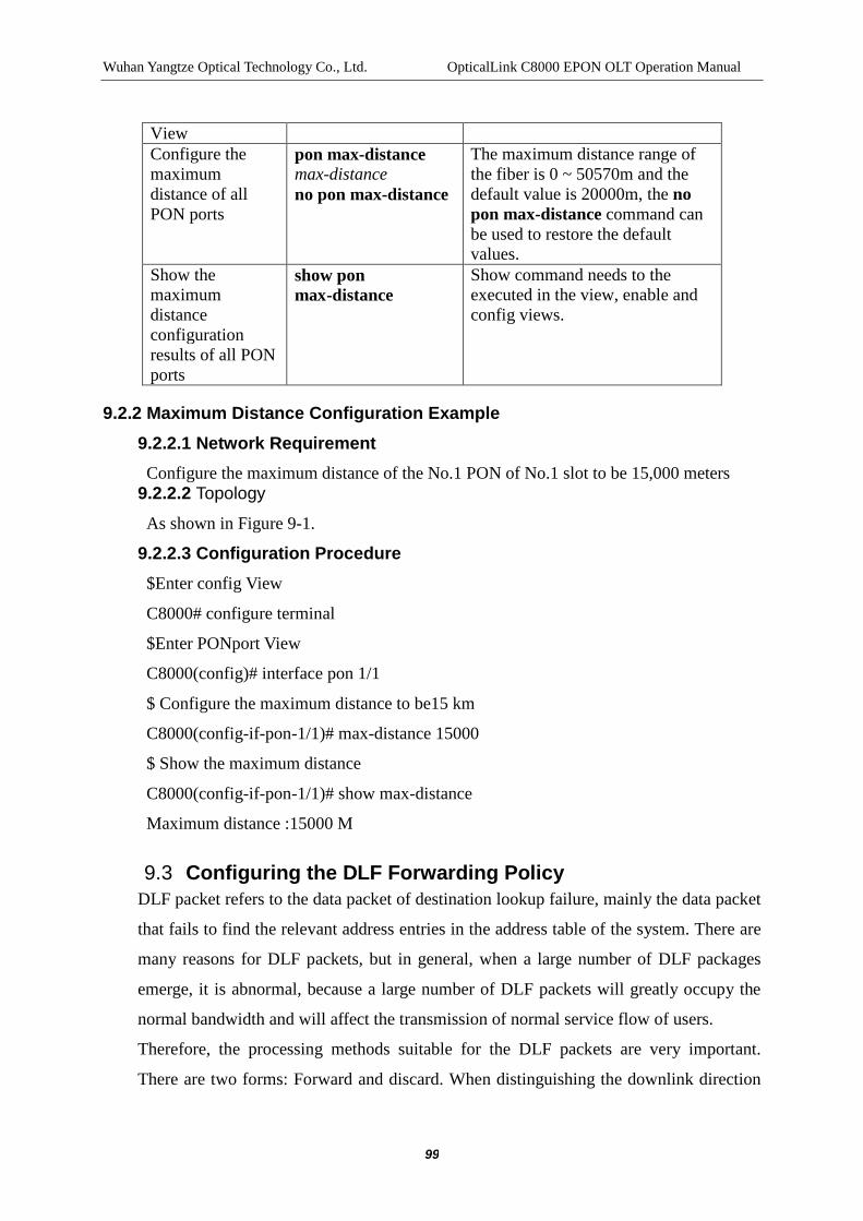
Wuhan Yangtze Optical Technology Co., Ltd. OpticalLink C8000 EPON OLT Operation Manual
99
View Configure the maximum distance of all PON ports
pon max-distance max-distance no pon max-distance
The maximum distance range of the fiber is 0 ~ 50570m and the default value is 20000m, the no pon max-distance command can be used to restore the default values.
Show the maximum distance configuration results of all PON ports
show pon max-distance
Show command needs to the executed in the view, enable and config views.
9.2.2 Maximum Distance Configuration Example 9.2.2.1 Network Requirement Configure the maximum distance of the No.1 PON of No.1 slot to be 15,000 meters
9.2.2.2 Topology As shown in Figure 9-1.
9.2.2.3 Configuration Procedure $Enter config View
C8000# configure terminal
$Enter PONport View
C8000(config)# interface pon 1/1
$ Configure the maximum distance to be15 km
C8000(config-if-pon-1/1)# max-distance 15000
$ Show the maximum distance
C8000(config-if-pon-1/1)# show max-distance
Maximum distance :15000 M
9.3 Configuring the DLF Forwarding Policy DLF packet refers to the data packet of destination lookup failure, mainly the data packet
that fails to find the relevant address entries in the address table of the system. There are
many reasons for DLF packets, but in general, when a large number of DLF packages
emerge, it is abnormal, because a large number of DLF packets will greatly occupy the
normal bandwidth and will affect the transmission of normal service flow of users.
Therefore, the processing methods suitable for the DLF packets are very important.
There are two forms: Forward and discard. When distinguishing the downlink direction

Wuhan Yangtze Optical Technology Co., Ltd. OpticalLink C8000 EPON OLT Operation Manual
100
from the uplink direction, the following forms can be extended, such as forwarding,
uplink discard, downlink discard, double-direction discard.
The main task for configuring the forwarding strategy of DLF is to meet the demands of
users in different network application environment. The system support four kinds of
modes based on the DLF forwarding strategy: forwarding, uplink discard, downlink
discard, double-direction discard.
[Note] By default, the system forwards the processing of the DLF packets.
9.3.1 Configuring the Forwarding Strategy of DLF Table 9-4 DLF Forwarding Strategy Configuration
Item Command Description Enter config View
configure terminal -
Enter pon View
interface pon interface-number interface-number refers to the PON port number.
Configure the DLF forwarding strategy
dlf (discard_ downlink |discard_ uplink |discard_uplink&downlink|forward) no dlf
Four kinds of strategies: discard the DLF packet of the downlink; discard the DLF packet of the uplink; discard the DLF packets of the downlink and uplink and forward the DLF packets of the downlink and uplink. The default strategy is the forwarding. The no dlf can be used for restoring the default strategy.
Show the configuration results
show dlf Show command needs to the executed in the pon view.
Enter config View
configure terminal -
Configure the DLF forwarding strategy
pon dlf (discard_ downlink |discard_ uplink |discard_uplink&downlink|forward) no pon dlf
Four kinds of strategies: discard the DLF packet of the downlink; discard the DLF packet of the uplink; discard the DLF packets of the downlink and uplink and forward the DLF packets of the downlink and uplink.
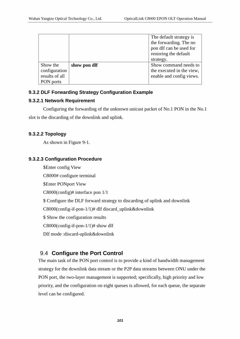
Wuhan Yangtze Optical Technology Co., Ltd. OpticalLink C8000 EPON OLT Operation Manual
101
The default strategy is the forwarding. The no pon dlf can be used for restoring the default strategy.
Show the configuration results of all PON ports
show pon dlf Show command needs to the executed in the view, enable and config views.
9.3.2 DLF Forwarding Strategy Configuration Example 9.3.2.1 Network Requirement
Configuring the forwarding of the unknown unicast packet of No.1 PON in the No.1
slot is the discarding of the downlink and uplink.
9.3.2.2 Topology As shown in Figure 9-1.
9.3.2.3 Configuration Procedure $Enter config View
C8000# configure terminal
$Enter PONport View
C8000(config)# interface pon 1/1
$ Configure the DLF forward strategy to discarding of uplink and downlink
C8000(config-if-pon-1/1)# dlf discard_uplink&downlink
$ Show the configuration results
C8000(config-if-pon-1/1)# show dlf
Dlf mode :discard-uplink&downlink
9.4 Configure the Port Control The main task of the PON port control is to provide a kind of bandwidth management
strategy for the downlink data stream or the P2P data streams between ONU under the
PON port, the two-layer management is supported; specifically, high priority and low
priority, and the configuration on eight queues is allowed, for each queue, the separate
level can be configured.

Wuhan Yangtze Optical Technology Co., Ltd. OpticalLink C8000 EPON OLT Operation Manual
102
When data congestion happens, the scheduling in accordance with the priority of the data
stream is made, thus realizing the aim of control.
9.4.1 Configure the Port Control Table 9-5 Port Control Configuration
Item Command Description Enter config View
configure terminal -
Enter pon View
interface pon interface-number
interface-number refers to the PON port number.
Configure the downlink port control
policer downstream queue0-pri queue1-pri queue2-pri queue3-pri queue4-pri queue5-pri queue6-pri queue7-pri high-pri-reserved no policer downstream
Configure the priopirties of eight queues with the range of 0 ~ 1, queue 0-pri to queue7-pri correspond to the priorities from Queue0 to Queue7. All the default values are 0. The high-pri-reserved is reserved for cache size of the high priority with the range of 0~131070 and the default value of 0. The no policer downstream command can be used for restoring the default values.
Configure the portP2P stream control
policer p2p queue0-pri queue1-pri queue2-pri queue3-pri queue4-pri queue5-pri queue6-pri queue7-pri high-pri-reserved no policer p2p
Configure the priopirties of eight queues with the range of 0 ~ 1, queue 0-pri to queue7-pri correspond to the priorities from Queue0 to Queue7. All the default values are 0. The high-pri-reserved is reserved for cache size of the high priority with the range of 0~131070 and the default value of 0. The no policer p2p command can be used for restoring the default values.
Show the configuration results
show policer Show the downstream and p2p information. Show command needs to the executed in the pon view.
Enter config View
configure terminal -
Configure the downlink port control
pon policer downstream queue0-pri queue1-pri queue2-pri queue3-pri queue4-pri queue5-pri queue6-pri queue7-pri high-pri-reserved
Configure the priopirties of eight queues with the range of 0 ~ 1, queue 0-pri to queue7-pri correspond to the priorities from Queue0 to Queue7. All the default values are 0. The

Wuhan Yangtze Optical Technology Co., Ltd. OpticalLink C8000 EPON OLT Operation Manual
103
no pon policer downstream
high-pri-reserved is reserved for cache size of the high priority with the range of 0~131070 and the default value of 0. The no pon policer downstream command can be used for restoring the default values.
Configure the portP2P stream control
policer p2p queue0-pri queue1-pri queue2-pri queue3-pri queue4-pri queue5-pri queue6-pri queue7-pri high-pri-reserved no policer p2p
Configure the priopirties of eight queues with the range of 0 ~ 1, queue 0-pri to queue7-pri correspond to the priorities from Queue0 to Queue7. All the default values are 0. The high-pri-reserved is reserved for cache size of the high priority with the range of 0~131070 and the default value of 0. The no pon policer p2p command can be used for restoring the default values.
Show the configuration results of all PON ports
show pon policer Show command needs to the executed in the view, enable and config views.
9.4.2 Example of Port Control Configuration 9.4.2.1 Network Requirement
The No. 1 PON of No.1 slot shall be subject to the following control rules.
For the downlink data stream, it needs to configure the priorities of eight queues and the
priorities must be reserved for the cache size of high priority:
Queue 0 High priority
Queue 1 High priority
Queue 2 Low priority
Queue 3 Low priority
Queue 4 Low priority
Queue 5 Low priority
Queue 6 Low priority
Queue 7 Low priority
Cache Size 130001
For the data stream between ONU in the PON, it needs to configure the priorities of

Wuhan Yangtze Optical Technology Co., Ltd. OpticalLink C8000 EPON OLT Operation Manual
104
eight queues and the priorities must be reserved for the cache size of high priority:
Queue 0 Low priority
Queue 1 Low priority
Queue 2 Low priority
Queue 3 Low priority
Queue 4 Low priority
Queue 5 Low priority
Queue 6 High priority
Queue 7 High priority
Cache Size 130002
9.4.2.2 Topology As shown in Figure 9-1.
9.4.2.3 Configuration Procedure $Enter config View
C8000# configure terminal
$Enter PONport View
C8000(config)# interface pon 1/1
$ Configure the downlink port control
C8000(config-if-pon-1/1)# policer downstream 1 1 0 0 0 0 0 0 0 130001
$ Configure the port control of P2P stream
C8000(config-if-pon-1/1)# policer p2p 0 0 0 0 0 0 1 1 0 130002
$ Show the configuration result
C8000(config-if-pon-1/1)#show policer
Olt downstream policer
Queue : 0 priority : 1
Queue : 1 priority : 1
Queue : 2 priority : 0
Queue : 3 priority : 0
Queue : 4 priority : 0
Queue : 5 priority : 0
Queue : 6 priority : 0

Wuhan Yangtze Optical Technology Co., Ltd. OpticalLink C8000 EPON OLT Operation Manual
105
Queue : 7 priority : 0
High priority reserved : 130001
-------------------------------
Olt p2p policer
Queue : 0 priority : 0
Queue : 1 priority : 0
Queue : 2 priority : 0
Queue : 3 priority : 0
Queue : 4 priority : 0
Queue : 5 priority : 0
Queue : 6 priority : 1
Queue : 7 priority : 1
High priority reserved : 130002
9.5 Configure the Protection Switching of Trunk Fiber The main task of the trunk fiber protection is to protect the trunk fiber connected to the
PON port by the double-path fiber redundancy backup. In the general network
applications, the trunk fiber comes from one PON port and is connected with each
ONU after passing through the optical splitter, once the trunk fiber has troubles, all
ONUs connected to the PON will cause the disruption of services. Under some special
application environment when the requirements on the stability and reliability of data
services are high, the users can greatly enhance the security and stability of data
services by the protection switching of trunk fiber.
The trunk fiber protection uses two optical interfaces for the service transfer, one of
which is A port and the other of which is B port. Under normal circumstances, B port
transfers the data and when the fiber connected with B port fails, the system will
automatically detect the abnormalities and then A port is activated, since then, A port
starts the data transmission instead of B port.
The system supports two kinds of switching models, mandatory and automatic, the
mandatory switching allows the user to switch between A port and B port at any time
and the automatic switching is specifically for the circumstances where no one is on
duty, for the latter, the system will, in accordance with the states of A/B fiber-optic links,
determine whether the switching operation is required.

Wuhan Yangtze Optical Technology Co., Ltd. OpticalLink C8000 EPON OLT Operation Manual
106
[Note] when the trunk fiber protection is applied, the 2: N optical splitter is required to
connect the two-way optical fiber with A port and B port. Only the LPU2P board can
support the optical fiber protection switching. LPU2P provides 4 optical interfaces, but
in fact there are only two PON interfaces inside.
9.5.1 Configuring the Trunk Fiber Protection Switching Table 9-6 Trunk Fiber Protection Switching Configuration
Item Command Description Enter config View
configure terminal -
Enter pon View interface pon interface-number interface-number refers to the PON port number.
Configuration Protection
trunkfiber set (force|auto) (a|b) Force refers to the mandatory switching and auto refers to the auto-switching; a refers to the mandatory switching to A port and b refers to the mandatory switching to B port.
Show configuration result
show trunkfiber Show command needs to the executed in the pon view.
9.5.2 Example of Trunk Fiber Protection Switching Configuration 9.5.2.1 Network Requirement The 1A port and 1B port of No.1 PON of No.1 slot are used for the trunk fiber
protection switching, of which, 1A is the port for trunk fiber and 1 B is the port for
backup fiber.
9.5.2.2 Topology

Wuhan Yangtze Optical Technology Co., Ltd. OpticalLink C8000 EPON OLT Operation Manual
107
Figure 9-2 Trunk Fiber Protection Topology
9.5.2.3 Configuration Procedure $Enter config View
C8000# configure terminal
$ Enter the port view of No.1 PON of No.1 slot
C8000(config)# interface pon 1/1
$ Mandatory switching to optical interface 1A
C8000(config-if-pon-1/1)# trunkfiber set force a
$Show configuration result
C8000(config-if-pon-1/1) show trunkfiber
slot 1 pon 1 switch mode is FORCE active port is A


Wuhan Yangtze Optical Technology Co., Ltd. OpticalLink C8000 EPON OLT Operation Manual
109
10 ONU CONFIGURATION MANAGEMENT
The ONU device is located at the client end, providing the port connecting with PON for the user. The ONU and the user can be connected with each other via Ethernet. The main functions of the ONU device are to receive the optical signals of the OLT device, translate the signals to the Ethernet data send to the user; and at the same time, translate the Ethernet data of the user and then send the data to the OLT device.
10.1 ONU Device Configuration Management
10.1.1 ONU Authorization Management
For the EPON system, the broadcast is applied at the downlink direction and the time-division multiplexing technology is applied at the uplink data channel, and the uplink data are send in different time slots by the control of OLT in ONU, if the ONU has not been authorized, then OLT will not send the uplink data in different time slots to ONU.
The authorization method of YOTC EPON system is that the MAC address of ONU is bound. It has been identified that only one ONU can be authorized when there is only a PON port. The authorization strategy can be divided into automatic and manual modes.
10.1.2 Configuring the Management Information of SFU-based ONU
For the SFU-based ONU, the binding authority can only be made on the premise that the IP address pool is subject to the configuration management and the VLAN is subject to the management.
Table 10-1 Configuring the Management Information of SFU-based ONU Item Command Description
Enter config View config terminal -
Configure the SFU-based ONU’s IP address pool
sfu manage startip ip network-mask gateway
Mandatory. ip is the starting IP, network-mask is a mask and gateway is the gateway.
Configure the SFU-based ONU’s administered VLAN
sfu manage vlan vlan-id
Mandatory. vlan-id is the ID of the administered VLAN with the range of 1 ~ 4094.
Show the SFU-based show sfu manage Show command needs to the executed

Wuhan Yangtze Optical Technology Co., Ltd. OpticalLink C8000 EPON OLT Operation Manual
110
ONU’s administered address pool
configuration in the enable or config view.
10.1.3 Configuring the ONU Automatic Binding Strategy
The automatic binding strategy is that when the ONU registers to the OLT, the OLT can automatically add the bound ONU resources into the legal ONU list, a maximum of 64 ONUs in the single PON port.
Table 10-2 Configuring the ONU Automatic Binding Strategy Item Command Description
Enter config View config terminal -
Configure ONU automatic binding strategy
authen-strategy auto Mandatory。
Show ONU binding strategy
show authen-strategy Optional, for inspecting the configuration
10.1.4 Configuring the ONU Manual Binding Strategy
The manual binding strategy is that when the ONU registers to the OLT, it is put into the illegal ONU list first and then the authorization is completed by the network administrator issues the binding command, as shown in Table 10-3.
Table 10-3 Configuring the ONU Manual Binding Strategy
Item Command Description
Enter config View config terminal -
Configure ONU manual binding strategy
authen-strategy manual Mandatory。
Show ONU binding strategy
show authen-strategy Optiona, for inspecting the configuration
Enter PON View interface pon interface-number
interface-number refers to the PON port number.
Bind ONU bind mdu onuid onuid mac-address mac-addr
onuid refers to the specified ONU ID, if the ID has

Wuhan Yangtze Optical Technology Co., Ltd. OpticalLink C8000 EPON OLT Operation Manual
111
type onu-type ip ipaddress netmask gateway bind sfu onuid onuid mac-address mac-addr type onu-type
already been used, the binding will not be successful; mac-addr refers to the MAC address of ONU; and onu-type refers to the type of ONU; ipaddress refers to the IP address; netmask refers to mask and gateway refers to gateway.
Unbind no bind onuid onu-id onuid refers to the specified ONU ID, with the range of 1~64 or all.
Show configuration result
show legal-onu-info Show command needs to the executed in the pon view.
Enter config View config terminal - Unbind all ONUs under the PON port
no bind all-onu Show command needs to the executed in the config view.
10.1.5 Example of ONU Binding Strategy Configuration
10.1.5.1 Network Requirement
Access to 32 ONUs under the PON port 3/1
Configure ONU manual binding strategy

Wuhan Yangtze Optical Technology Co., Ltd. OpticalLink C8000 EPON OLT Operation Manual
112
10.1.5.2 Network Diagram
Figure 10-1 ONU Management Network Diagram
10.1.5.3 Configuration Procedure
$ Configure the ONU binding strategy to be manual mode
C8000(config)# authen-strategy manual
$ Manually bind all SFU-type ONUs under PON port3/1
C8000(config)# interface pon 3/1
C8000(config-if-pon-3/1)#bind sfu onuid all
$ Show the all legal ONUs under the PON port3/1
C8000(config-if-pon-3/1)#show legal-onu-info
ONU-ID LLID State Mac Address Type Dist (M) SLA IP address ONU-ID ActiveTime Description
---------------------------------------------------------------------------------------------------------------------------
03/01:01 1 active 00:1a:69:30:0b:42 M3-0420P 46 1

Wuhan Yangtze Optical Technology Co., Ltd. OpticalLink C8000 EPON OLT Operation Manual
113
125.10.19.130 03/01:01 2007/01/01 00:03:32 ONU:03/01:01
……………………………………………
03/01:32 32 active 00:1a:69:30:0b:4a M3-0421P 49 1 125.10.19.131 03/01:01 2007/01/01 00:03:52 ONU:03/01:32
-----------------------------------------------------------------------------------------------------------------------------
Total: 32 legal ONUs bound
10.1.6 Restarting and Deregistering
The user can restart or deregister ONU. The ONU can be divided into the legal ONU and the illegal ONU in accordance with their authorization states, so the restarting and deregistering on the two ONUs are different; specifically, for the illegal ONU, it needs to specify the llid of the ONU for restarting or deregistering; and for the legal ONU, it needs to specify the ONU ID to complete the operation.
10.1.6.1 Prerequisites
For the legal ONU, it needs to be successfully binded, see section 10.1.1 "ONU Authorization Strategy Management” for specific operations.
10.1.6.2 ONU Restarting and Deregistering Table 10-4 Restarting and Deregistering under the pon view
Item Command Description Enter config View
configure terminal -
Enter pon View
interface pon interface-number interface-number refers to the PON port number.
Restart the legal ONU
reset legal-onu onu-id onuid refers to the specified ONU ID with the range of 1~64。
Deregister legal ONU
deregister legal-onu onu-id onuid refers to the specified ONU ID。
Restart the illegal ONU
reset illegal-onu (mac-addr | all) mac-addr refers to the MAC address of ONU
Deregister illegal ONUONU
deregister illegal-onu mac-addr mac-addr refers to the MAC address of ONU

Wuhan Yangtze Optical Technology Co., Ltd. OpticalLink C8000 EPON OLT Operation Manual
114
Table 10-5 Restarting and Deregistering under the ONU view Item Command Description
Enter config View
configure terminal -
Enter onu View interface onu interface-number interface-number refers to the onu port number.
Restart the legal ONU
reset
Deregister legal ONU
deregister
10.1.7 ONU Restarting Example
10.1.7.1 Network Requirement
Restart the legal ONU3/1:1 of the EPON system
10.1.7.2 Network Diagram
See“10.1.1”Network Diagram
10.1.7.3 Configuration Procedure
Configure under the PON mode
$Enter the PON 3/1 view
C8000(config)# interface pon 3/1
$ Restart ONU3/1:1
C8000(config-if-pon-3/1)# reset legal-onu 1
Configure under the ONU View
$Enter ONU3/1:1 View
C8000(config)# interface onu 3/1:1
$ Restart ONU3/1:1
C8000(config-if-onu-3/1:1)# reset

Wuhan Yangtze Optical Technology Co., Ltd. OpticalLink C8000 EPON OLT Operation Manual
115
10.1.8 FEC Configuration
FEC (Forward Error Correction) is the important technology in the PON system, and FEC can correct the error generated in the transmission and reduce the BER (bit error rate). By the FEC technology, the optical power budget can be increased, so that the distance between the OLT and the ONU can be increased or the split ration of PON can be increased or the reliability of digital channels can be improved.
Table 10-6 Configure FEC of ONU Item Command Description
Enter config View
configure terminal -
Enter onu View interface onu interface-number interface-number refers to the onu number.
Enable FEC fec (enable | disable) - Show configuration result
show fec Show command needs to the executed in the onu view.
10.1.9 Configure the ONU Port Isolation
This configuration is mainly used for isolating the data traffic of ONU ports. When the ONU is attached with multiple PCs and the mutual visits between the PCs are not allowed, the configuration can be used.
Table 10-7 Configure the ONU Port Isolation Item Command Description
Enter config View
configure terminal -
Enter onu View interface onu interface-number interface-number refers to the onu number.
Enable port isolation
isolate (enable | disable) -
Show configuration result
show isolate Show command needs to the executed in the onu view.
Configuring the Loop Detection of the Port

Wuhan Yangtze Optical Technology Co., Ltd. OpticalLink C8000 EPON OLT Operation Manual
116
10.1.10 Configuring the Loop Detection of the Port
The task of the operation is the test on the connection between ONU and OLT, so as to check whether the connection is good.
Table 10-8 Loop Detection of the Link Item Command Description
Enter config View
configure terminal -
Enter onu View interface onu interface-number interface-number refers to the onu number.
Enable Loop Detection
loopback -
Note:
This system provides the function of automatic recovery. 5 seconds after the user starts loop-back test, the loop-back test will automatically shut down.
10.1.11 P2P Operation
This operation is mainly used for managing the connectivity of data stream between ONUs under the same PONs, P2P (point-to-point) data refer to the data channels between ONUs, respectively unicast, broadcast and unicast of unknown addresses (dlf) . The system can respectively manage the data of broadcast and unicast of unknown addresses and can regulate the P2P traffic.
Note:
By default, the ONUs under the same PON port cannot communicate with each other, if the communication is required, the p2p function must be enabled, and by default, the p2p discard the dlf packets and broadcast packets. According to IEEE 802.3-2005 protocol, the point-to-point operation between ONUs of the same PON is not supported, we we do not recommend users to use the p2p function.
Table 10-9 p2p Configuration Operation

Wuhan Yangtze Optical Technology Co., Ltd. OpticalLink C8000 EPON OLT Operation Manual
117
Item Command Description Enter config View configure terminal - Enter onu View interface onu
interface-number interface-number refers to the onu number.
Configure the strategy of p2p unicast packets
p2p access-control (enable|disable)
enable refers to the communication of unicasts between the ONU and other ONU of the PON.
Show configuration result
show p2p access-control
Show command needs to the executed in the onu view.
Configure the strategy of p2p broadcast and unknown unicast packets
p2p dlf (discard|flood) broadcast (discard|flood)
discard refers to that the communication is inaccessible and flood refers to that the communication is accessible.
Show configuration result
show p2p config Show command needs to the executed in the onu view.
Configure the p2p traffic policing
p2p policing max-band max-burst (enable | disable)
max-band refers to the maximum bandwidth; max-burst refers to the maximum burst frame and enable refer that the high priority level is enabled.
Show p2p traffic policing configuration
show p2p policing Show command needs to the executed in the onu view.
10.1.11.1 P2P Configuration Example (Modified in the V400R007 series in part)
10.1.11.1.1 Network Requirement
Configure to ensure that p2p function between the ONU3/1:1 and the ONU3/1:32 under PON is enabled.
10.1.11.1.2 Network Diagram
See“10.1.1”Network Diagram。
10.1.11.1.3 Configuration Procedure
$Enter PON 3/1 View
C8000(config)# interface pon 3/1
$ Enable p2p function and forward the learning packet of broadcast.
C8000(config-if-pon-3/1)# p2p access-control enable

Wuhan Yangtze Optical Technology Co., Ltd. OpticalLink C8000 EPON OLT Operation Manual
118
$ Check the enabling state of p2p function
C8000(config-if-pon-3/1)#show p2p access-control
P2p state : enable
10.1.12 VOIP Port Operation
The operation is mainly used for configuring the VOIP global parameters of OLT terminal and VOIP parameters of ONU terminal. Note: before configuring the VOIP parameters, it needs to configure the relevant GE port and PON port into hybrid, add the GE port into VOIP VLAN and untagged, set PVID to VOIP VLAN, and add PON port into VOIP VLAN and tagged, and set PVID to 1. And then configure the VOIP.
10.1.12.1 Configuring the VOIP Parameters of OLT Terminal
Configure the VOIP global parameters of OLT terminal, including VOIP VLAN, SIP protocol and VOIP parameters.
Table 10-10 VOIP Operation of OLT Terminal Item Command Description
Enter config View configure terminal - Configure the VLAN of VOIP and its priority
voip vlan vlan-id [cos-vlaue] no voip vlan [<0-7>]
vlan-id refers to the VLAN ID of VOIP and cos-vlaue refers to the priority of VOIP VLAN with the range of 0 ~ 7. This configuration is optional. The no voip vlan command can be used to delete VOIP VLAN.
Configure the global parameters of SIP protocol
sip template mode (proxy|mapping) register-server-ip ip-address1 port port-num1 proxy-server-ip ip-address2 port port-num2 register-interval interval-time
proxy| mapping is the model of SIP; ip-address1 is the IP of the registration server; port-num1 is the port of the fourth floor of the server; ip-address2 is the IP of the proxy server; port-num2 is the port of the fourth floor of the proxy server; and interval-time is the interval of registration with the range of 60 ~ 3600.
Configure the global parameters of VOIP
voip template fax (transparent|t38) sil-compress (enable|disable) echocancel (enable|disable) dtmf (transparent|rfc2833)
transparent | t38 is the fax mode; enable | disable is the static compression switch; enable | disable is the echo suppression switch;

Wuhan Yangtze Optical Technology Co., Ltd. OpticalLink C8000 EPON OLT Operation Manual
119
codec (auto|g711a|g711u|g729|g723) input-gain i-gain output-gain o-gain callidmode (fsk|dtmf)
transparent | rfc2833 is the DTMF mode; auto | g711a | g711u | g729 | g723 is the voice coding; i-gain is the inputted gain for setting the voice signal power of the microphone with the range of -31 ~ 31; o-gain is the outputted gain for setting the voice signal power of the handset with the range of -31 ~ 31; and fsk | dtmf is the caller display mode.
Show global VOIP Configuration
show voip configuration Show command needs to the executed in the enable or config view.
10.1.12.2 Example of the Configuration of VOIP Parameters of OLT Terminal
10.1.12.2.1 Network Requirement
Configure VOIP VLAN to500 and priority to 6; configure the global parameters of SIP protocol (mode of proxy, IP of the registration server is 172.20.10.10, the number of the fourth-floor port is 5060, the IP of the proxy server is 172.20.10.10, the number of the fourth-floor port is 5060 and the registration interval of 360) and the global parameters of VOIP (fax mode is transparent, silence compression switch is disable, echo suppression switch is enable, DTMF mode is rfc2833, speech coding method is auto, inputted gain is 2, outputted gain is 3 and the caller display mode is dtmf).

Wuhan Yangtze Optical Technology Co., Ltd. OpticalLink C8000 EPON OLT Operation Manual
120
10.1.12.2.2 Network Diagram
Figure 10-2 Networking of VOIP under the same ONU
10.1.12.2.3 Configuration Procedure
$ Configure the global parameters of SIP protocol
C8000(config)#sip template mode proxy register-server-ip 172.20.10.10 port 5060 proxy-server-ip 172.20.10.10 port 5060 register-interval 360
$ Configure the global parameters of VOIP
C8000(config)# voip template fax tran sil-compress disable echocancel enable dtmf rfc2833 codec auto input-gain 2 output-gain 3 callidmode dtmf
$ Show the global VOIP configuration
C8000(config)# show voip configuration
Voip Configuration:
Vlan ID : 0
Vlan Priority : 0
Fax Mode : transparent
Silence Compress : off

Wuhan Yangtze Optical Technology Co., Ltd. OpticalLink C8000 EPON OLT Operation Manual
121
Echo Cancel : on
DTMF Mode : rfc2833
Codec Type : Auto
Input Gain : 2
Output Gain : 3
Call ID : DTMF
Sip Mode : Proxy
Sip IAD : 5060
Sip Reg Server IP : 172.20.10.10
Sip Reg Server Port : 5060
Sip Proxy Server IP : 172.20.10.10
Sip Proxy Server Port : 5060
Sip regist interval : 360
access node id : /0/0
10.1.12.3 Configuring the VOIP Parameters of the ONU Terminal
The configuration of the VOIP parameters of the ONU terminal includes IP, mode, parameters of port number user, hotline and dial-up plans, etc.
Table 10-11 VOIP Port Operation of ONU Item Command Description
Enter config View configure terminal - Enter onu View interface onu
interface-number interface-number refers to the onu number.
Enable| Disable the VOIP function of the port
voip voip-port-number (enable | disable)
voip-port-number refers to the port number of VOIP. The default status is enable.
Show configuration result
show voip-port-state voip-port-number
Show command needs to the executed in the onu view.
Configure the static IP parameters of
voip ip static-ipaddress ip-address network-mask gateway
Optional. ip-address refers to the static IP address; network-mask is the mask and the gateway is the gateway.

Wuhan Yangtze Optical Technology Co., Ltd. OpticalLink C8000 EPON OLT Operation Manual
122
VOIP Configure the parameters of port number user of the SIP protocol of VOIP
voip ip usrname username password password
Optional. username refers to the user name for PPPoE dial-up and password is the password for PPPoE dial-up.
Configure IP mode voip ip mode (dhcp|dhcp+|pppoe|pppoe+|static)
Mandatory. Before using the command for configuring the VOIP IP into the static mode, it must use the voip ip static-ip address command, or the system will give the prompt of bad parameters.
Show the IP configuration of VOIP
show voip ip configuration Show command needs to the executed in the onu view.
Configure the parameters of port number user of the SIP protocol of VOIP
sip port voip-port-num num number usrname username passwd password
Mandatory. voip-port-num refers to the VOIP port number of ONU; number refers to the port number of SIP protocol; username refers to the user name; and password refers to the user’s password.
Configure the port hotline parameters of VOIP
sip port voip-port-num hotline (hot|warm|off) num number
voip-port-num refers to the VOIP port number; hot | warm | off refers to the hotline mode of the port; and the number refers to the hotline number.
Show the SIP port configuration of VOIP
show voip port voip-port-num Show command needs to the executed in the onu view.
Configure the dial-up plan of VOIP
voip dialplan index content no voip dialplan index
This is the serial number for dial-up plan and the content of dial-up plan. The no voip dialplan command can be used for deleting the specified dial-up plan.
Show the configuration of the dial-up plan of VOIP
show voip dialplan The command can only be used after the voip dialplan is configured, only in this way, the configuration results can be checked, or no display can be shown. Show command needs to the executed in the onu view.
Check the protocol used for VOIP of ONU
show voip protocol Show command needs to the executed in the onu view.
Note:

Wuhan Yangtze Optical Technology Co., Ltd. OpticalLink C8000 EPON OLT Operation Manual
123
The VOIP port of ONU terminal is enabled by default.
10.1.12.4 Example of the Configuration of VOIP Parameter of ONU Terminal
10.1.12.4.1 Network Requirement
Configure the static IP address of VOIP of ONU10/1:1 to 172.20.10.20, the mask to 255.255.0.0 and the gateway to 172.20.10.1; configure the IP mode to the static mode; configure the port1 user number in SIP protocol to 1001, user name to yotc1001, password to 123456; and configure the port2 user number in SIP protocol to1002, user name to yotc1002, password to 123456;
10.1.12.4.2 Network Diagram
Figure 10-3 Networking of VOIP under the same ONU
10.1.12.4.3 Configuration Procedure
$ Configure the static IP address of the VOIP of ONU10/1:1
C8000(config-if-onu-10/1:1)#voip ip static-ipaddress 172.20.10.20 255.255.0.0 172.20.10.1
$ Configure the VOIP IP mode of ONU10/1:1

Wuhan Yangtze Optical Technology Co., Ltd. OpticalLink C8000 EPON OLT Operation Manual
124
C8000(config-if-onu-10/1:1)#voip ip mode static
$ Configure the VOIP SIP port1 of ONU10/1:1
C8000(config-if-onu-10/1:1)#sip port 1 num 1001 usrname yotc1001 passwd 123456
$ Configure the VOIP SIP port2 of ONU10/1:1
C8000(config-if-onu-10/1:1)#sip port 2 num 1002 usrname yotc1002 passwd 123456
$ Configure the VOIP configuration of ONU10/1:1
C8000(config-if-onu-10/1:1)#show voip ip configuration
IP configuration infomation:
IP mode : static
static ip : 172.20.10.20
mask : 255.255.0.0
gateway : 172.20.10.1
user name : ---
password : ---
$ Check the configuration of VOIP SIP port 1 of ONU10/1:1
C8000(config-if-onu-10/1:1)#show voip port 1
Sip Port Number : 1001
Sip Port User Name : yotc1001
Sip Port Password : 123456
Sip Port Hot Line Mode : 0
Sip Port Hot Line Number : ---
Register Status : offline
Physical Status : hang-up
$ Check the configuration of VOIP SIP port 2of ONU10/1:1

Wuhan Yangtze Optical Technology Co., Ltd. OpticalLink C8000 EPON OLT Operation Manual
125
C8000(config-if-onu-10/1:1)#show voip port 2
Sip Port Number : 1002
Sip Port User Name : yotc1002
Sip Port Password : 123456
Sip Port Hot Line Mode : 0
Sip Port Hot Line Number : ---
Register Status : offline
Physical Status : hang-up
10.1.12.5 Setup of WAN IP
This configuration is mainly used to the static IP address information of the WAN port (port of the inband management ONU system, that is, the PON port of ONU) of the ONU, and used by the ONU to register SIP servers and used to facilitate to pass through the web network management of ONU.
Table 10-12 Configuration of WAN Port IP of ONU Item Command Description
Enter config View
configure terminal -
Enter onu View
interface onu interface-number interface-number refers to the onu number.
Ation refers to configure the WAN port IP address
wan-ip ipaddress netmask gateway ipaddress refers to the IP address; netmask refers to the mask and gateway refers to the gateway
Show configuration result
show wan-ip Show command needs to the executed in the onu view.
10.2 ONUport Configuration Management The main task for the port configuration management of ONU is the configuration
operation on the Ethernet ports of ONU.
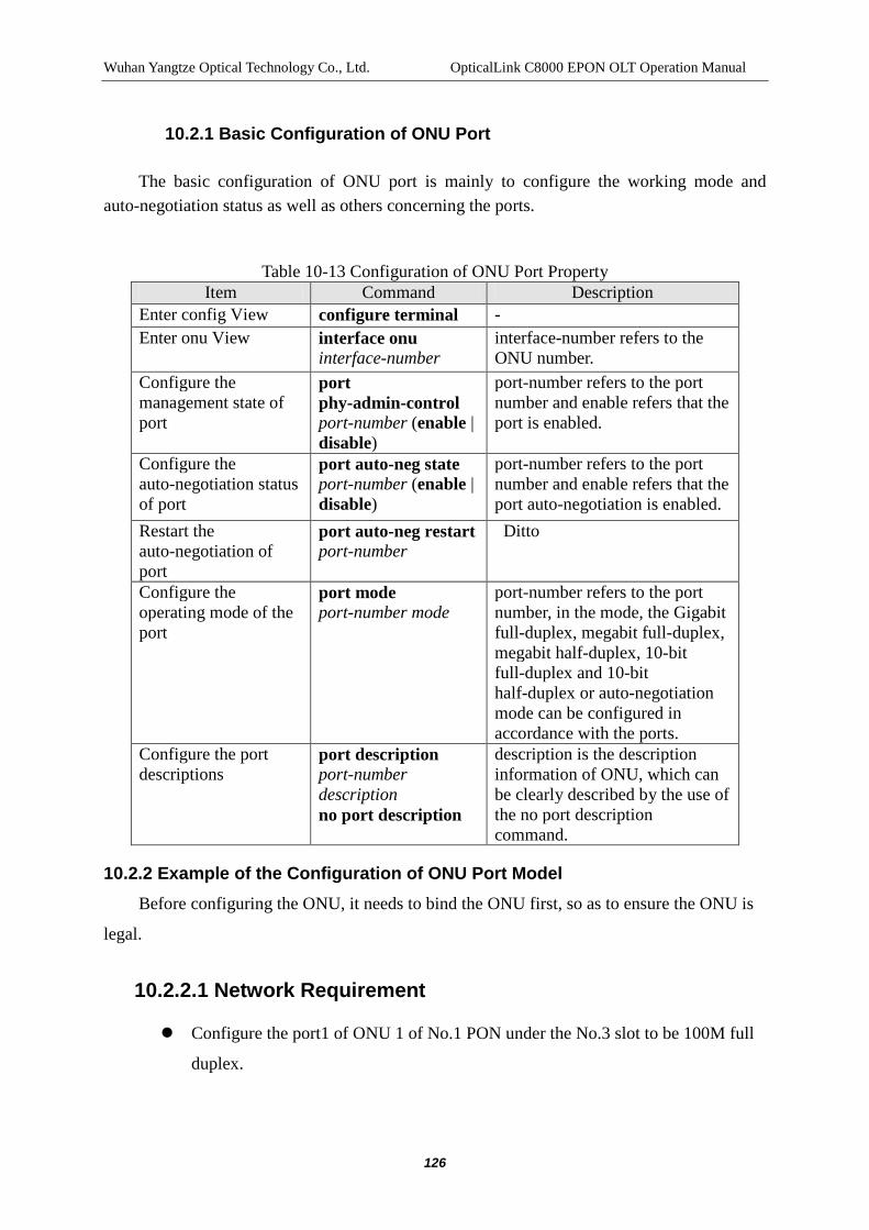
Wuhan Yangtze Optical Technology Co., Ltd. OpticalLink C8000 EPON OLT Operation Manual
126
10.2.1 Basic Configuration of ONU Port
The basic configuration of ONU port is mainly to configure the working mode and auto-negotiation status as well as others concerning the ports.
Table 10-13 Configuration of ONU Port Property
Item Command Description Enter config View configure terminal - Enter onu View interface onu
interface-number interface-number refers to the ONU number.
Configure the management state of port
port phy-admin-control port-number (enable | disable)
port-number refers to the port number and enable refers that the port is enabled.
Configure the auto-negotiation status of port
port auto-neg state port-number (enable | disable)
port-number refers to the port number and enable refers that the port auto-negotiation is enabled.
Restart the auto-negotiation of port
port auto-neg restart port-number
Ditto
Configure the operating mode of the port
port mode port-number mode
port-number refers to the port number, in the mode, the Gigabit full-duplex, megabit full-duplex, megabit half-duplex, 10-bit full-duplex and 10-bit half-duplex or auto-negotiation mode can be configured in accordance with the ports.
Configure the port descriptions
port description port-number description no port description
description is the description information of ONU, which can be clearly described by the use of the no port description command.
10.2.2 Example of the Configuration of ONU Port Model Before configuring the ONU, it needs to bind the ONU first, so as to ensure the ONU is
legal.
10.2.2.1 Network Requirement
Configure the port1 of ONU 1 of No.1 PON under the No.3 slot to be 100M full
duplex.

Wuhan Yangtze Optical Technology Co., Ltd. OpticalLink C8000 EPON OLT Operation Manual
127
10.2.2.2 Network Diagram
See“10.1.1”Network Diagram.
10.2.2.3 Configuration Procedure
$ Enter the onu view of ONU 3/1:1:
C8000(config)# interface onu 3/1:1
$ Configure the port1 mode of ONU3/1:1 to be 100M full duplex
C8000(config-if-onu-3/1:1)# port mode 1 100Mf
$Show configuration result
C8000(config-if-onu-1/1:1)# show port mode 1
PORT-ID Port-Mode
--------------------------------------------
1 100MF
--------------------------------------------
10.2.3 Configuring the Flow Control of the Port If the congestion happens to ONU when the UNI of ONU and the device connected
enable the flow control, the UNI will send the packet to the device connected to notify
the device connected to suspend sending packet, after the device connected receives the
packet, it suspends sending packet, thus avoiding the packet loss.
Table 10-14 Configuration of the Flow Control of the Port Item Command Description
Enter config View configure terminal - Enter onu View interface onu interface-number interface-number
refers to the ONU number.
Configure the flow control of port
port flow-control port-number (enable | disable)
port-number refers to the port number.
Show configuration result
show port flow-control port-number
Show command needs to the executed in the onu view.
10.2.4 ONU Port’s Flow Control Configuration Example Before the configuration of the ONU, bind the ONU first to ensure the ONU is legal.

Wuhan Yangtze Optical Technology Co., Ltd. OpticalLink C8000 EPON OLT Operation Manual
128
10.2.4.1 Network Requirement
Enable the flow control of the port 1 of the ONU 1 of No.1 PON of the No. 3 slot.
10.2.4.2 Network Diagram
See“10.1.1”Network Diagram。
10.2.4.3 Configuration Procedure
$ Enter the onu mode of ONU 3/1:1:
C8000(config)# interface onu 3/1:1
$ Enable the flow control of the port 1 of ONU3/1:1
C8000(config-if-onu-3/1:1)# port flow-control 1 enable
$ Show the configuration results
C8000(config-if-onu-1/1:1)# show port flow-control 1
Port-Id Flowcontrol
--------------------------------------------
1 enable
--------------------------------------------
10.2.5 Configuring the Port Rate Limitation
The main function of the port rate limitation of the ONU is to limit the uplink data of the ONU.
Table 10-15 Configure the Rate Limitation of ONU Port Item Command Description
Enter config View
configure terminal -
Enter onu View
interface onu interface-number
interface-number refers to the ONU number.

Wuhan Yangtze Optical Technology Co., Ltd. OpticalLink C8000 EPON OLT Operation Manual
129
Configure the rate limitation of port
port policing port-number rate-value cbs ebs no port policing port-number
port-number refers to the port number; rate-value refers to the rate limitation value; cbs and ebs refer to the burst frame processing parameters, generally configured into the default value of 65535. The no port policing command can be used for cancelling the rate-limiting configuration of the port.
Show configuration result
show port policing port-number
Show command needs to the executed in the onu view.
Note:
The unit is kbps, for example, if 50M is required, then it is 50000kbps.
10.2.6 Configuration Example Before the configuration of the ONU, bind the ONU first to ensure the ONU is legal.
Network Diagram Configure the rate of the uplink data of port 1 of the ONU 1 of No.1
PON of the No. 3 slot to be 50M
10.2.6.1 Network Diagram
See“10.1.1”Network Diagram。
10.2.6.2 Configuration Procedure
$ Enter the onu mode of ONU A:
C8000(config)# interface onu 3/1:1
$ Configure the uplink data rate of port 1 ONU3/1:1 to be 50M.
C8000(config-if-onu-1/1:1)# port policing 1 50000 65535 65535
$ Show the configuration results
C8000(config-if-onu-1/1:1)# show port policing 1

Wuhan Yangtze Optical Technology Co., Ltd. OpticalLink C8000 EPON OLT Operation Manual
130
Port-Id Policing-State Cir Cbs Ebs
---------------------------------------------------------------------------------
1 active 50000 65535 65535
---------------------------------------------------------------------------------
10.2.7 Display and Maintenance of the Basic Configuration of Port
C8000 system provides the display of the basic configuration of ONU port. Table 10-16 Display of the Basic Configuration of ONU Port Item Command Description
Enter config View configure terminal - Enter onu View interface onu
interface-number interface-number refers to the ONU number.
Show the management state of port
show port phy-admin-state port-number
Show command needs to the executed in the onu view.
Show the link state of port show port link-state port-number
Ditto
Show the self-adaption state of port
show port auto-neg port-number Ditto
Show the actual port connection mode
show port mode port-number Ditto
Show the desired port connection mode
show port exp-mode port-number Ditto
Show the informed auto-negotiation state of port
show port advertised-tech-ability port-number
Ditto
Show the current auto-negotiation state of port
show port local-tech-ability port-number
Ditto
Show port descriptions show port description Ditto
10.3 Classification and Marking Configuration Management
10.3.1 Introduction to Classification and Marking
The main task of classification and marking is to provide the priority marking on the uplink data stream. The classification and marking can realize the mandatory modification of priority tags. In accordance with the different matching rules for user configuration, the marking on different flows can be realized respectively. At present, the system supports the following matching rules: VLAN ID, Ethernet type, Ethernet Priority,

Wuhan Yangtze Optical Technology Co., Ltd. OpticalLink C8000 EPON OLT Operation Manual
131
IP type, TOS field, IP Precedence, source port number of transport layer, destination port number of transport layer, source IP address, destination IP address, source MAC ADDRESS and destination MAC ADDRESS, etc.
10.3.2 Classification and tag Template Operation
The user can configure the template for classification and marking in advance and configure the matching rules and operating conditions in the template. In a classification and marking template, the user can configure a number of matching rules. The system supports a maximum of 8 rules.
Table 10-17 Configuring the Classification and tag Template Item Command Description
Enter config View configure terminal - Add a classification and marking template
classification-marking add listid ruleid queue-number pri match-field match-value match-type
Listid refers to the number of the classification tag template; ruleid refers to the number of the rule; queue-number refers to the number of the queue; pri refers to the tag priority; match-field refers to the domain matched; match-value refers to the value matched; match-type refers to the type of matching; the equal, not equal, greater than, less than and other forms of matching are provided here.
Modify or add a classification and marking rule
classification-marking mod listid ruleid queue-number pri match-field match-value match-type
Ditto
Delete a classification and marking rule or the entire template
classification-marking del rule listid ruleid classification-marking del entry listid
del entry refers to delete a classification tag template; del rule refers to delete a sub-rule of the classification tag template.
Show configuration result show classification-marking listid
Show command needs to the executed in the config view.
10.3.2.1 Configure to connect the ONU port with the classification and tag templates
After the user defined the template, the template can be applied to all legal ONU in any a

Wuhan Yangtze Optical Technology Co., Ltd. OpticalLink C8000 EPON OLT Operation Manual
132
PON.
Table 10-18 Configure to connect the ONU port with the classification and tag templates
Item Command Description Enter config View
configure terminal -
Enter onu View
interface onu interface-number
interface-number refers to the ONU number.
Apply the classification tag templates
port classification-marking port-number listid
no port classification-marking port-number
port-number refers to the number of the port that requires the application of classification template; listid refers to the number of the classification tag template to be applied. The no port classification-marking port-number command can be used to cancel the classification tag templates applied to the ONU port.
Show configuration result
show port classification-marking port-number
Show command needs to the executed in the onu view.
10.3.3 Classification and Marking Configuration Example
10.3.3.1 Network Requirement
Set the revised priority of the uplink VLAN 10 packets to 7 for the port 1 of ONU3/1:1 and map to Queue4.
10.3.3.2 Network Diagram
See“10.1.1”Network Diagram.
10.3.3.3 Configuration Procedure
$ Establish the revised priority of the uplink VLAN 10 packet to 7 and map to the rule of Queue4
C8000(config)# classification-marking add 1 1 4 7 vlan-id 10 equal
$ Apply the classification and tag templates to port1 of ONU3/1:1
C8000(config)# interface onu 3/1:1

Wuhan Yangtze Optical Technology Co., Ltd. OpticalLink C8000 EPON OLT Operation Manual
133
C8000(config-if-onu-3/1:1)# port classification-marking 1 1
10.4 SLA Configuration Management
10.4.1 Introduction to SLA
SLA refers to the Service Level Agreement, specifically, the agreement between the service provider and the customers on the key service targets and responsibilities of both parties in the provision of services.
EPON system should use the dynamic bandwidth allocation (DBA) mechanism to improve the utilization of the upstream bandwidth of the system and ensure the fairness and QoS of services. Besides, the EPON system should be able to allocate the bandwidth authorization in accordance with the queue status reported by LLID.
DBA should support the following three kinds of bandwidth allocation:
Fixed Bandwidth: The OLT periodically sends the authorizations of fixed number to the ONU. It is recommended to use the smaller cycle time and the higher grant frequency for bandwidth allocation. The fixed bandwidth is fully reserved for particular ONU or the specific service of ONU, even under the circumstances when the ONU has no fixed uplink bandwidth service flow, the OLT can send the authorization of the fixed bandwidth to the ONU, and the bandwidth can not be used by other ONU. The fixed-bandwidth is mainly used in the ONU with TDM service (or LLID) in order to ensure the smaller transmission delay of the service.
Assured bandwidth: The bandwidth is specifically for ONU; the OLT authorizes the bandwidth in accordance with the REPORT information of ONU. When the actual service flow of the ONU fails to reach the assured bandwidth, the DBA mechanism of OLT should be able to allocate its remaining bandwidth to the services of other ONUs.
Best Effort Bandwidth: When the bandwidth of the EPON interface has not been occupied by the services of higher priority, the ONU can use such bandwidth. The best effort bandwidth is to allocate the authorizations for the ONU by the OLT according to the REPORT information of all online ONUs in the PON system and the occupancy of bandwidth of PON interfaces. The system does not guarantee that the ONU or the specific service of the ONU can get a certain amount of bandwidth. The type belongs to the service of the lowest priority.
The realization of SLA of the EPON system in the downlink direction is by traffic policing. The traffic policing is mainly for limiting the maximum flow rate. When the traffic rate reaches the maximum rate configured, the exceeded traffic will be discarded; as a result, the

Wuhan Yangtze Optical Technology Co., Ltd. OpticalLink C8000 EPON OLT Operation Manual
134
traffic rate of jagged peaks and troughs is shown
10.4.2 Configuring SLA
This configuration task is to set the service level; the main approach is to realize the different service levels by configuring different types of bandwidth allocation. The EPON system can allocate different bandwidths in accordance with the service demands of different customers. For large and medium-sized enterprises, the EPON system can increase the bandwidth in order to run the services; for ordinary customers, the EPON system can limit the bandwidth to avoid the bandwidth waste.
10.4.2.1 SLA Template Operation
The user can pre-configure the SLA template and define the parameters necessary for the uplink and downlink in the template, by default, the system has one-layer SLA, in addition, the user can customize 9-layer SLA, namely, the system can provide a maximum of 10-layer SLA.
Table 10-19 SLA Template Operation Item Command Description
Enter config View
configure terminal -
Add an SLA sla add slaid up-cos up-fix-bw up-gr-bw up-best-bw up-max-burst down-cos down-fix-bw down-gr-bw down-best-bw down-max-burst
slaid refers to the serial number of SLA template; up-cos refers to the priority level of the uplink data; up-fix-bw refers to fixed bandwidth of uplink; up-gr-bw refers to the assured bandwidth of unlink and up-best-bw refers to the best-effort-bandwidth of uplink and up-max-burst refers to the maximum burst frame length of the packet; down-cos refers to priority level of the downlink data; down-fix-bw refers to fixed bandwidth of downlink; down-gr-bw refers to the assured bandwidth of downlink anddown-best-bw refers to the best-effort-bandwidth of downlink and down-max-burst refers to the maximum burst frame length of downlink packet;
Modify an SLA
sla mod slaid (upstream|downstream)cos
Ditto

Wuhan Yangtze Optical Technology Co., Ltd. OpticalLink C8000 EPON OLT Operation Manual
135
fix-bw gr-bw best-bw max-burst
Delete an SLA
sla del slaid Ditto
Show configuration result
show sla Show command needs to the executed in the config view.
Note:
SLA template 1 is a default template, which cannot be deleted or modified or created. The default value of the template 1 has the uplink priority level of , the fixed bandwidth of uplink of 10000kbps, the assured bandwidth of unlink of uplink of 10000kbps, the maximum uplink bandwidth of 1000000kbps and the maximum uplink burst frame length of 16777215bytes; the downlink priority level of 0, the fixed bandwidth of downlink of 10000kbps, the assured bandwidth of downlink of 10000kbps, the maximum downlink bandwidth of 999994kbps and the maximum burst frame length of downlink of 16777215bytes.
10.4.2.2 Configure the Relations between ONU and SLA Template
After the template is defined, the user can use the template in any a legal ONU under any a PON port.
Table 10-20 Configure the Relations between ONU and SLA Template Item Command Description
Enter config View
configure terminal -
Enter onu View interface interface-number interface-number refers to the ONU number.
Apply SLA sla sla-number sla-number refers to the number of the SLA template applied. The sla 1 command can used for restoring the default SLA template.
Show show sla Show command needs

Wuhan Yangtze Optical Technology Co., Ltd. OpticalLink C8000 EPON OLT Operation Manual
136
configuration result
to the executed in the onu view.
Note:
When the ONU is bound, the associated SLA template 1 by default is used.
10.4.3 SLA Configuration Example
10.4.3.1 Network Requirement
Set the minimum uplink bandwidth for ONU3/1:1 to 64000Kbit/s, the maximum uplink bandwidth to 320000Kbit/s, the maximum downlink bandwidth to 500000Kbit/s and the maximum burst frame length of downlink to 4000Bytes.
10.4.3.2 Network Diagram
See“10.1.1”Network Diagram。
10.4.3.3 Configuration Procedure
$ Establish the SLA template featuring minimum uplink bandwidth of 64000Kbit/s, the maximum uplink bandwidth of 320000Kbit/s, the maximum downlink bandwidth of 500000Kbit/s and the maximum burst frame length of downlink of 4000Bytes.
C8000(config)# sla add 2 0 10000 64000 320000 4000 0 10000 10000 500000 4000
$ Apply the SLA template to ONU3/1:1
C8000(config)# interface onu 3/1:1
C8000(config-if-onu-3/1:1)# sla 2

Wuhan Yangtze Optical Technology Co., Ltd. OpticalLink C8000 EPON OLT Operation Manual
137
11 RSTP CONFIGURATION MANAGEMENT
11.1 Introduction to RSTP Protocol
The concepts and principles on RSTP of the device are fully consistent with the Ethernet switch; therefore, the following RSTP protocol is introduced by taking the Ethernet switch as an example.
STP refers to the Spanning Tree Protocol. The protocol can be used in the loop network to block some redundant paths by the regulated algorithm and to prune the loop network into the loop-free tree network, thus avoiding the proliferation and infinite loop of packets in the loop network.
The basic principle of STP is to pass the special protocol message (In the IEEE 802.1D protocol, the protocol message is known as BPDU) between switches, so as to determine the network topology. The BPDU contains enough information to ensure the switch can complete the spanning tree calculation.
The BPDUmainly includes the following contents:
(1) Root Bridge ID :comprising of the priority of the root and the MAC address;
(2) Root path cost :shortest path cost to the root;
(3) Designated bridge ID:, comprising of the priority of the designated switch and the MAC address;
(4) Designated port ID: comprising of the priority of the designated port and the port number;
(5) MessageAge: BPDU age;
(5) MaxAge: Maximum age of BPDU
(7) HelloTime: Cycle for sending BPDU ;
(8) ForwardDelay: Forwarding delay of the of port state;
The following contents will introduce the designated port and the designated switch.

Wuhan Yangtze Optical Technology Co., Ltd. OpticalLink C8000 EPON OLT Operation Manual
138
Figure 11-1: Designated Port and Designated Switch
For a switch, the designated switch is the one directly connected with the device and responsible for forwarding data packets to the device and the designated port is the one to which the designated switch forwards the data. For a LAN, the designated switch is the one responsible for forwarding data packets to this network segment and the designated port is the one to which the designated switch forwards the data. As shown in the figure, if Lanswitch A forwards the data to Lanswitch B through port Ethernet 0/1, then the Lanswitch A is the designated switch in the BPDU of Lanswitch B and the designated port is the port Ethernet 0/1 of Lanswitch A; the LAN is connected with two switches: Lanswitch B and Lanswitch C, of which, the Lanswitch B is for transmitting the data packets to the LAN, then the designated switch of LAN is Lanswitch B and the designated port is Ethernet 0/4 of Lanswitch B.
The following will explain the calculation of spanning tree by an example. See the following figure for specific network:

Wuhan Yangtze Optical Technology Co., Ltd. OpticalLink C8000 EPON OLT Operation Manual
139
Figure 11-2: Ethernet Switch Network
To make the information be clear, only the first four items of the BPDU are shown in the example: root ID (indicated by the priority of Ethernet switch), root path cost, ID of designated switch (indicated by the priority of Ethernet switch) and ID of designated port (indicated by port number). As shown in the above figure, the priority of Lanswitch A is 0, the priority of Lanswitch B is 1 and the priority of Lanswitch C is 2. See the figure for the path cost of each link, 5, 10 and 4 respectively.
(1) Initial state: Each port of the switch will generate the BPDU with the root of itself, the root path cost is 0, the designated switch ID is the ID of the switch and the designated port is the port of the switch.
Lanswitch A:
Port Ethernet 0/1 BPDU:{0,0,0,e0/1}
Port Ethernet 0/2 BPDU:{0,0,0,e0/2}
Lanswitch B:
Port Ethernet 0/7 BPDU:{1,0,1,e0/7}
Port Ethernet 0/4 BPDU:{1,0,1,e0/4}
Lanswitch C:
Port Ethernet 0/1 BPDU:{2,0,2,e0/1}。

Wuhan Yangtze Optical Technology Co., Ltd. OpticalLink C8000 EPON OLT Operation Manual
140
Port Ethernet 0/5 BPDU:{2,0,2,e0/5}。
(2) Select the Optimal BPDU
Each switch sends out its own BPDU. When the port receives the BPDU with priority lower than its priority, the BPDU with lower priority will be discarded and the BPDU of the port will not subject to any change. On the contrary, when the port receives the BPDU with priority higher than its priority, the BPDU with higher priority will be used to update the BPDU of the port, that is, the BPDU with higher priority will replace the original BPDU of the port. After that, the BPDU with higher priority will be compared with the BPDU of other ports, and finally the optimal BPDU will be selected.
The principle for comparison is that the smaller the root ID is, the higher the priority of the BPDU is, if case the root IDs are the same, the root path costs can be compared, the specific method is as follows: Add the root path cost of the BPDU and the corresponding path cost of the port, set the amount to S, the smaller the S is, the higher the priority of the BPDU is. However, if the root path costs are the same, then the designated switch IDs, the designated port IDs and the port IDs receiving the BPDU can be compared in turn. To make the explanation be more clearly, the manual here only describes the comparison of root IDs, by which, the optimal BPDU can be determined.
(3) Selecting the root port and update the BPDU of the designated port in accordance with the blocking redundant links.
The port receiving the optimal BPDU is the root port and the BPDU of the port is not changed; for other ports, when the BPDU of a port blocks the root port in the updating of the process (2), the BPDU of the port remains the same, but the port will not transmit data and only receive but not send BPDUs; if the BPDU of a port is not updated in the process (2), then the BPDU of the designated port must be subject to the following changes: the root ID is replaced into the root ID of the BPDU of the root port; the root path cost is replaced into the sum of the root port cost of the BPDU of the root port and the corresponding root port cost of the root port; the ID of designated switch is replaced into the ID of the switch; the designated port ID is replaced into the ID of the port.
The comparison of various switches is as follows:
Lanswitch A:
Port Ethernet 0/1 receives the BPDU of Lanswitch B, when the BPDU of the port has the priority higher than the priority of the BPDU received, the BPDU received will be discarded, similar to the port Ethernet 0/2. Lanswitch A finds the roots and the designated switches of the BPDU of each port belong to the Lanswitch A, then Lanswitch A believes
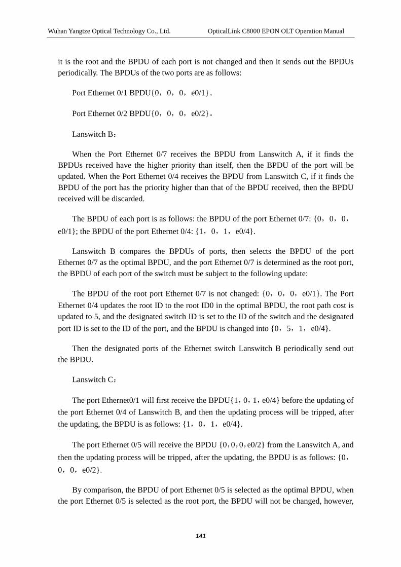
Wuhan Yangtze Optical Technology Co., Ltd. OpticalLink C8000 EPON OLT Operation Manual
141
it is the root and the BPDU of each port is not changed and then it sends out the BPDUs periodically. The BPDUs of the two ports are as follows:
Port Ethernet 0/1 BPDU{0,0,0,e0/1}。
Port Ethernet 0/2 BPDU{0,0,0,e0/2}。
Lanswitch B:
When the Port Ethernet 0/7 receives the BPDU from Lanswitch A, if it finds the BPDUs received have the higher priority than itself, then the BPDU of the port will be updated. When the Port Ethernet 0/4 receives the BPDU from Lanswitch C, if it finds the BPDU of the port has the priority higher than that of the BPDU received, then the BPDU received will be discarded.
The BPDU of each port is as follows: the BPDU of the port Ethernet 0/7: {0,0,0,e0/1}; the BPDU of the port Ethernet 0/4: {1,0,1,e0/4}.
Lanswitch B compares the BPDUs of ports, then selects the BPDU of the port Ethernet 0/7 as the optimal BPDU, and the port Ethernet 0/7 is determined as the root port, the BPDU of each port of the switch must be subject to the following update:
The BPDU of the root port Ethernet 0/7 is not changed: {0,0,0,e0/1}. The Port Ethernet 0/4 updates the root ID to the root ID0 in the optimal BPDU, the root path cost is updated to 5, and the designated switch ID is set to the ID of the switch and the designated port ID is set to the ID of the port, and the BPDU is changed into {0,5,1,e0/4}.
Then the designated ports of the Ethernet switch Lanswitch B periodically send out the BPDU.
Lanswitch C:
The port Ethernet0/1 will first receive the BPDU{1,0,1,e0/4} before the updating of the port Ethernet 0/4 of Lanswitch B, and then the updating process will be tripped, after the updating, the BPDU is as follows: {1,0,1,e0/4}.
The port Ethernet 0/5 will receive the BPDU {0,0,0,e0/2} from the Lanswitch A, and then the updating process will be tripped, after the updating, the BPDU is as follows: {0,0,0,e0/2}.
By comparison, the BPDU of port Ethernet 0/5 is selected as the optimal BPDU, when the port Ethernet 0/5 is selected as the root port, the BPDU will not be changed, however,

Wuhan Yangtze Optical Technology Co., Ltd. OpticalLink C8000 EPON OLT Operation Manual
142
the port Ethernet0/1 will be blocked and the BPDU of the port will remain the same, at the same time, the port will not receive the data transmitted from Lanswitch B (excluding the protocol message of STP) until the spanning tree calculation is made due to same reasons, from example, the link from Lanswitch B to Lanswitch C is down or the BPDU of higher priority is received by the port.
And the port Ethernet 0/1 receives the updated BPDU {0,5,1,e0/4} from Lanswitch B. Because the BPDU received has the higher priority than the original BPDU, the updated BPDU will then be updated into {0,5,1,e0/4} again.
At the same time, the BPDU from Lanswitch A received by the port Ethernet 0/5 will not be updated, and the BPDU remains {0,0,0,e0/2}. By comparison, the BPDU of port Ethernet 01 is selected as the optimal BPDU, and the port Ethernet 0/1 is selected as the root port, its BPDU will not be changed, however, the port Ethernet0/5 will be blocked and the BPDU of the port will remain the same, at the same time, the port will not receive the data transmitted from Lanswitch A until the spanning tree calculation is made due to same reasons, from example, the link from Lanswitch B to Lanswitch C is down.
At that time, the spanning tree is stable and the tree shape is as follows, the root is Lanswitch A:
Figure 11-3: Finally Stable Spanning Tree
To make everything be clear, the manual simplifies the process, for example, the root ID and the ID of designated switch must comprise of the switch priority and the MAC address in the process of actual operation; and the ID of designated port must comprise of the port priority and the port MAC address; in the updating of BPDU, not only the above four items will change, the BPDU will also change in accordance with the fixed principles. But the

Wuhan Yangtze Optical Technology Co., Ltd. OpticalLink C8000 EPON OLT Operation Manual
143
calculation is almost the same.
The passing mechanism of the BPDU of the spanning tree protocol is as follows:
When the network is initialized, all switches take themselves as the roots, the designated ports of the switches send the BPDU of themselves with the cycle of HelloTime periodically; if the port receiving the BPDU is the root port, the MessageAge in the BPDU is increased in accordance with certain principle, and the timer is started to time the BPDU; if a certain path fails, the root port of the path will no longer receive any a new BPDU and the old BPDU will be discarded due to time-out, thus causing the spanning tree recalculation, generating a new path to replace the failed path and restoring the network connectivity.
However, if the new BPDU after the re-calculation does not spread throughout the network immediately, the old root port and designated port that fail to find the change of the topology will continue forwarding data along the original path; while if the newly elected root port and designated port immediately forward data, the temporary path loop may be caused; therefore, the protocol applies the state transition mechanism, that is to say, before the root port and designated port re-start forwarding data, they must pass through an intermediate state, and the intermediate state can be changed into the forwarding state after the ForwardDelay, which ensures the new BPDU has spread throughout the entire network.
The RSTP achieved in the device is the optimization version of Spanning Tree Protocol. The "Rapid" refers to that the delay when the root port and designated port enter the forwarding state is greatly reduced under certain conditions, thus reducing the time required for the stability of network topology. The convergence time for network change is very important for the high-delay-sensitive applications such as voice, video, etc.
The conditions for the rapid migration of root port status are: the old root port of the switch has stopped forwarding data and the designated upstream port has begun forwarding the data.
The conditions for the rapid migration of port status of the designated port are:
Edge port: the port does not connect with any switches directly or indirectly. In case the designated port is the edge port, it is allowed to directly enter the forwarding state;
The port is connected with the point-to-point link, that is, the port is the main port of the trunk port or the full-duplex port, and the user can configure the port to be the point-to-point connection. If the designated port is connected with the point-to-point link, it can immediately enter the forwarding state after the response is gotten by the handshake with the downstream switch;

Wuhan Yangtze Optical Technology Co., Ltd. OpticalLink C8000 EPON OLT Operation Manual
144
The switches applied the Rapid Spanning Tree Protocol are compatible with the switches applied the Spanning Tree Protocol. The packets of the two protocols can be identified and applied to the spanning tree calculations.
11.2 OLT RSTP Configuration Management
11.2.1 List of RSTP Configuration Tasks
The configuration tasks can only take effect after the RSTP is started. Before starting the RSTP, the relevant parameters for the device or Ethernet ports can be configured, and after the RSTP is closed, the configuration parameters can be saved, when the RSTP restarts, these parameters will take effect.
The list of RSTP main configuration tasks is as follows:
Enable and Disable the RSTP Features of the Device
Enable and Disable the RSTP Features of the Port
Configure the Working Mode of the RSTP Protocol
Configure the Bridge’s Priority of the Device
Configure the Forward Delay Characteristics of the Device
Configure the Hello-time Characteristics of the Device
Configure the Max Age Characteristics of the Device
Configure the Maximum Sending Rate of the Specific Port
Configure the Specific Port to be EdgePort or Not
Configure the Path Cost of the Specific Port
Configure the Priority of the Specific Port
Configure whether the Specific Port is Connected with the Point to Point Link or not
Under normal circumstances, enabling the RSTP features of the device realizes the RSTP function, in case of special requirements, the configuration of relevant parameters can be made.

Wuhan Yangtze Optical Technology Co., Ltd. OpticalLink C8000 EPON OLT Operation Manual
145
11.2.2 Enable/Disable the Spanning Tree Features of Device Table 11-1 Enable/Disable the Spanning Tree Features of Device
Item Command Description
Enter config View configure terminal -
Enable/disable RSTP protocol of device
rstp(enable | disable) Control the enabling and disabling of the global RSTP protocol. It is disabled by default.
Note: After the RSTP features of the device are enabled, part of the network resources will be occupied.
11.2.3 Enable/Disable the Spanning Tree Features of Port
In order to flexibly control the RSTP, it can disable the RSTP features of port, so as to ensure the port does not participate in spanning tree calculations.
Table 11-2 Enable/Disable the Spanning Tree Features of Port
Item Command Description
Enter config View configure terminal -
Enter xe、ge View interface x-ethernet interface-number
or interface gigabit-ethernet interface-number
-
Enable/disable RSTP features of port
rstp port (enable | disable) By default, after the RSTP of the device is enabled, activate the RSTP protocols in all ports.
11.2.4 Configure the Working Mode of Spanning Tree Protocol
RSTP protocol can communicate with STP protocol. If the bridge running the STP protocol exits in the switching network, the command can be used to configure that the

Wuhan Yangtze Optical Technology Co., Ltd. OpticalLink C8000 EPON OLT Operation Manual
146
current RSTP protocol runs in mode compatible to STP. Table 11-3 Working Mode of Spanning Tree Protocol Configuration
Item Command Description
Enter config View configure terminal -
Configure the operating mode of RSTP protocol to STP compatible mode / RSTP mode
rstp mode (stp | rstp) -
Restore the operating mode of RSTP protocol to the default value
no rstp mode By default, RSTP protocol runs in the RSTP mode.
In case the bridge running the STP protocol exits in the switching network, RSTP protocol can automatically migrate to STP, if it runs in the compatible mode, the manual configuration of users is not needed.
11.2.5 Configure the Bridge Priority of Device
The priority of the bridge of the device determines whether the device can be selected as the root of the entire spanning tree. The priority of smaller configuration can designate the device as the root of the spanning tree.
Table 11-4 Configure the Bridge Priority of Device
Item Command Description
Enter config View configure terminal -
Configure the Bridge Priority of Device
rstp bridge-priority pri pri is the priority of the bridge, with the range of 0 ~ 61440 and the smallest particles of 4096.
Restore the bridge priority of device to the default value
no rstp bridge-priority The command can restore the default value of the priority of bridge to 32768.
Note: if the priority of all bridges in the entire switching network uses the same value, then the bridge with the smallest MAC address must be selected as the root. Under the circumstances when the RSTP protocol is enabled, if the priority of the bridge is

Wuhan Yangtze Optical Technology Co., Ltd. OpticalLink C8000 EPON OLT Operation Manual
147
configured, the spanning tree recalculation will be caused.
11.2.6 Configure the Forward Delay Characteristics of Device
The link failure will trigger the network for the recalculations of spanning tree structure. However, the new configuration information re-calculated cannot immediately spread throughout the network; if the newly elected root port and designated port immediately began the data forwarding, the temporary loopback path may be caused. Therefore, the protocol applies a mechanism of state transition, then the root port and designated port has to pass through an intermediate state before the root port and designated port re-start data forwarding, the intermediate state can only enter the forwarding state after passing through the forward delay which ensures the new configuration information has spread to the entire network. The Forward Delay characteristic of the bridge is relevant to the diameter of the switching network. In general, the larger the network diameter is, the longer the time configured for the forward delay is.
Table 11-5 Configure the Forward Delay Characteristics of Device
Item Command Description
Enter config View configure terminal -
Configure the Forward Delay characteristics of the device
rstp timer forward-delay centiseconds
centiseconds refers to the forwarding timer of forward-delay with the range of 400 ~ 3000 and in unit of hundredths of a second.
Restore the Forward Delay of the device to the default value
no rstp timer forward-delay
Restore the default value to 15 seconds.
Note: if the Forward Delay configuration is too small, the temporary redundant paths may be introduced; if the Forward Delay configuration is too large, the connectivity of the network cannot be restored for a long time. It is recommended that the user applies the default values.
11.2.7 Configure the Hello Time Characteristics of Device
The suitable Hello Time value is to ensure the network bridge can find the link failure in the network but not to take up too much network resources.
Table 11-6 Configure the Hello Time Characteristics of Device Item Command Description

Wuhan Yangtze Optical Technology Co., Ltd. OpticalLink C8000 EPON OLT Operation Manual
148
Enter config View configure terminal -
Configure the Hello Time characteristics of the device
rstp timer hello centiseconds centiseconds refers to the hello timer with the range of 100~1000 and in unit of hundredths of a second.
Restore the Hello Time of the device to the default value
no rstp timer hello Restore the default value to 2 seconds.
Note: if the Hello Time value is too larger, the packet loss of link may be caused, and the bridge may believe that there are link failures, as a result, the system may start to recalculate the spanning tree; if the Hello Time value is too smaller, the bridge may frequently send messages, and the burden to network and CPU may be increased. It is recommended that the user applies the default values.
11.2.8 Configure the Max Age Characteristics of Device
Max Age is used to determine whether the information configured is the outdated parameters, the user can implement the configuration according to the actual situation of the network.
Table 11-7 Configure the Max Age Characteristics of Device
Item Command Description
Enter config View
configure terminal
-
Configure the Max Ag characteristics of the device
rstp timer max-age centiseconds
centiseconds refers to the max-age timer with the range of 600~4000 and in unit of hundredths of a second. The value of max-age has the following relations with hello and forward-delay:
2×(forward-delay-1)>=max-age>=2×(hello+1)。
Restore the Max Age of the device to the default value
no rstp timer max-age
Restore the default value to 20 seconds.

Wuhan Yangtze Optical Technology Co., Ltd. OpticalLink C8000 EPON OLT Operation Manual
149
Note: If the Max Age configuration is too small, the spanning tree calculation will be more frequent and even the network congestion may mistakenly regarded as link failure; if the Max Age configuration is too large, the link failures may be not detected in a timely manner, as a result, the network self-adaptability may be reduced. It is recommended that the user applies the default values.
11.2.9 Configure the Maximum Transmission Speed of a Specific Port
The maximum transmission speed of the Ethernet port has relationship with the physical state and the network structure of the port, the user can implement the configuration according to the actual situation of the network.
Table 11-8 Configure the Maximum Transmission Speed of a Specific Port
Item Command Description
Enter config View configure terminal -
Configure the maximum transmission speed of the port
rstp transmit-limit rate-limit rate-limit refers to the rate limit for packet transmission with the range of 1~255 and without any units.
Restore the maximum transmission speed of the port to the default value
no rstp transmit-limit Restore the default value to 3 seconds.
Note: If this parameter is configured too large, too many network resources may be taken up. It is recommended that the user applies the default values.
11.2.10 Configure the Specific Port to be Edge Port or Not
If the current Ethernet port is not connected to the Ethernet port of any other bridges, it needs to configure the port to be edge port, in this way, the port can be directly changed into the forwarding state and the unnecessary migration time can be reduced. If a particular port is configured for edge port, but the port is connected to the port of other bridge, then the RSTP protocol can automatically detect and re-configure as the non-edge port.
Table 11-9 Configure the Specific Port to be Edge Port or Not
Item Command Description

Wuhan Yangtze Optical Technology Co., Ltd. OpticalLink C8000 EPON OLT Operation Manual
150
Enter config View configure terminal -
Enter xe、ge View interface x-ethernet interface-number
or interface gigabit-ethernet interface-number
-
Configure the port as an edge port / non-edge port
rstp edged-port (enable | disable)
-
Restore the port to the default value
no rstp edged-port By default, all Ethernet ports of the device are configured as edge port.
Note: if the current Ethernet ports changes from the non-edge port into the edge port, it is recommended that the user manually configures the parameters as the edge port. RSTP protocol cannot detect whether the non-edge port has been transformed into the edge port. For the port directly connecting with the user terminals, please set the port as the edge port, which may quickly migrate the port to the forwarding state, so as to prevent the unnecessary time wasted in startup.
11.2.11 Configure the Path Cost of a Specific Port
The path cost of the Ethernet port is relevant to the link rate of the port, the higher the link rate is, the smaller the parameter configuration is. RSTP protocol can automatically detect the previous link rate of the current Ethernet port and can convert into the corresponding path cost.
Table 11-10 Configure the Path Cost of a Specific Port
Item Command Description
Enter config View configure terminal -
Enter xe、ge View interface x-ethernet interface-number
or interface gigabit-ethernet interface-number
-

Wuhan Yangtze Optical Technology Co., Ltd. OpticalLink C8000 EPON OLT Operation Manual
151
Configure the Path Cost of the port
rstp cost cos -
Restore the Path Cost of the port to the default value
no rstp cost By default, the device can directly get the path cost of the port from the link rate.
Note: the path cost for configuring the Ethernet port can cause the recalculation of the spanning tree. It is recommended that the user can use the default values to make the RSTP protocol to calculate the path cost of the current Ethernet port.
11.2.12 Configure the Priority of a Specific Port
Setting the priority of Ethernet port can specify a particular Ethernet port included in the spanning tree. In general, the smaller the value configured is, the higher the port priority is, the higher the likelihood that Ethernet port is included in the spanning tree is. If all Ethernet ports of the bridge use the parameter values of the same priority, the priority of the Ethernet port depends on the index number of the Ethernet port.
Table 11-11 Configure the Priority of a Specific Port
Item Command Description
Enter config View configure terminal -
Enter xe、ge View interface x-ethernet interface-number
or interface gigabit-ethernet interface-number
-
Configure port priority
rstp port-priority port-priority
port-priority refers to the port priority with the range of 0~240 and the smallest particles of 16.
Restore the port priority to the default
no rstp port-priority Restore the default value of the priority of all

Wuhan Yangtze Optical Technology Co., Ltd. OpticalLink C8000 EPON OLT Operation Manual
152
value Ethernet ports of the bridge to 128.
Note: the change of the priority of Ethernet port can cause the recalculations of spanning tree.
11.2.13 Configure the Specific Port to be Connected with Point to Point Link or not
The two ports connected with the point to point link can quickly migrate to the forwarding state by the simultaneous transmission of packets, reducing the unnecessary forwarding delay time. If this parameter is configured to automatic mode, RSTP protocol can automatically detect whether the current Ethernet port is connected with point to point links.
Table 11-12 Configure the Specific Port to be Connected with Point to Point Link or not
Item Command Description
Enter config View configure terminal -
Enter xe、ge View interface x-ethernet interface-number
or interface gigabit-ethernet interface-number
-
Configure the port to be connected with point to point link
rstp point-to-point (auto | force-false | force-true)
auto, force-false and force-true are respectively for configuring the connection between the port and the point to point link, the disconnection between the port and the point to point link and the automatic mode.
Restore the parameter to the default value
no rstp point-to-point Restore the default configuration of auto.

Wuhan Yangtze Optical Technology Co., Ltd. OpticalLink C8000 EPON OLT Operation Manual
153
Note: the current Ethernet port must be the main port of aggregation port and must be full-duplex mode, only in this way, the point to point link can be configured, or the configuration is invalid. The user can manually configure the connection between current Ethernet port and point to point link, it is recommended to use the automatic mode.
11.3 Monitoring and Maintenance of OLT RSTP
The following operations are for RSTP monitoring and maintenance, for the specific use of the command, please see command line manual.
Table 11-13 RSTP Monitoring and Maintenance
Item Command Description
Enter config View configure terminal -
Monitor and update the status of RSTP port
rstp check port-link Monitor and update the status of RSTP port (UP/DOWN)。
Show the Bridge-info of RSTP
show rstp bridge-info Show command needs to the executed in the view, enable orconfig view.
Show the brief RSTP information of a specific port
show rstp brief [slotid] If no slot number is provided, then the information of all ports will be shown. Show command needs to the executed in the view, enable orconfig view.
Show the RSTP information of all ports of the particular slot
show rstp slot (scu | slotid) Show command needs to the executed in the view, enable orconfig view.
Enter xe、ge View interface x-ethernet interface-number
or interface gigabit-ethernet interface-number
-

Wuhan Yangtze Optical Technology Co., Ltd. OpticalLink C8000 EPON OLT Operation Manual
154
Show the detailed RSTP information of a specific port
show rstp interface-info Show command needs to the executed in the xe, or ge view.
11.4 Configure ONU RSTP
11.4.1 Enable/disable the Spanning Tree Characteristics of ONU Table 11-14 Enable/disable the Spanning Tree Characteristics of ONU
Item Command Description
Enter config View configure terminal -
Enter onu View interface onu interface-number
-
Enable/disable RSTP function of ONU
rstp (enable | disable) By default, RSTP is disabled.
Note: after the RSTP characteristics of the device are enabled, the network resources in parts are occupied.
11.5 Monitoring and Maintenance of ONU RSTP Table 11-15 Monitoring and Maintenance of ONU RSTP
Item Command Description
Enter config View configure terminal -
Enter onu View interface onu interface-number
-
Show the RSTP status of ONU port
show port rstp-state (uniid | all)
Show the RSTP status of ONU port. Show command needs to the executed in the onu view.
Show the RSTP function status of ONU
show rstp-state Show the RSTP function status of ONU. Show command

Wuhan Yangtze Optical Technology Co., Ltd. OpticalLink C8000 EPON OLT Operation Manual
155
needs to the executed in the onu view.

Wuhan Yangtze Optical Technology Co., Ltd. OpticalLink C8000 EPON OLT Operation Manual
156
12 LINK AGGREGATION CONFIGURATION
MANAGEMENT
12.1 Introduction to Link Aggregation
The link aggregation, known as port aggregation, aggregates multiple ports to form an aggregation group, so as to share the ingress/egress loads among the member ports of the aggregation group and to provide higher connection reliability.
The basic configuration for the ports of an aggregation group must be same, of which, the basic configuration includes port priority, pvid, port vlan mode, vlan configuration, qos (scheduling algorithms, relations between priority and queue), acl (rules of application)
VLAN configuration includes: VLAN that is allowed to pass through the port and the default VLAN ID of the port.
QoS configuration includes: priority marking, default 802.1p priority, queue mapping, scheduling mode, etc.
Port attribute configuration includes: VLAN types (Hybrid port or Ttransparent port, etc.) that must be consistent.
ACL configuration: applied ACL list
The port of the smallest port number in the port aggregation group is the main port of the aggregation group, and other ports are the member ports of the aggregation group.
Under normal circumstances, the port aggregation does not limit the port rate and duplex mode before the aggregation. But in case of the following circumstances, the system will implement the corresponding operations:
For the port at the DOWN state at the initial state, the port rate and the duplex mode will not be limited in aggregation.
For the port at the DOWN state at present but was at the UP state and the port rate and duplex mode are designated by negotiation or compulsion, the port rate and duplex mode must be same in aggregation.
For an aggregation group, when the rate and duplex mode of the port in the aggregation group change, the system will not release the aggregation, and the ports in the aggregation group will be in the normal working condition. However, the packet

Wuhan Yangtze Optical Technology Co., Ltd. OpticalLink C8000 EPON OLT Operation Manual
157
loss may happen in the forwarding of the port if the rate of the main port reduces and its duplex mode changes. To ensure the port selection of data stream is under control and the data load balances and other factors, the port selection criteria must be followed to ensure the single data streams uses the same exit as much as possible.
12.2 Link Aggregation Group Configuration
The user can create the aggregation group for port by the following commands. The user can delete any port aggregation group formed, then the port of the aggregation group will completely leave the aggregation group. After the aggregation group of the port is created, the user can manually add/delete member ports.
Table 12-1 Link Aggregation Group Configuration
Item Command Description
Enter config View config terminal -
Create aggregation group for port
link-aggregation group group-id psc psc description description
Mandatory
The system can configure a maximum of 32 aggregation groups with each aggregation group composed of a maximum of eight member ports.
Modify the path selection strategy of the aggregation group for port
link-aggregation group group-id new-psc psc
Optional
Modify the description of the aggregation group for port
link-aggregation group group-id new-desc description
Optional
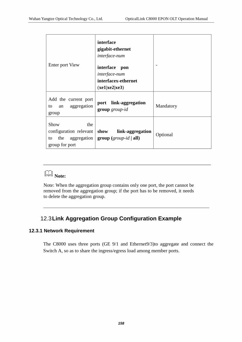
Wuhan Yangtze Optical Technology Co., Ltd. OpticalLink C8000 EPON OLT Operation Manual
158
Enter port View
interface gigabit-ethernet interface-num
interface pon interface-num interfacex-ethernet (xe1|xe2|xe3)
-
Add the current port to an aggregation group
port link-aggregation group group-id
Mandatory
Show the configuration relevant to the aggregation group for port
show link-aggregation group (group-id | all)
Optional
Note:
Note: When the aggregation group contains only one port, the port cannot be removed from the aggregation group; if the port has to be removed, it needs to delete the aggregation group.
12.3 Link Aggregation Group Configuration Example
12.3.1 Network Requirement
The C8000 uses three ports (GE 9/1 and Ethernet9/3)to aggregate and connect the Switch A, so as to share the ingress/egress load among member ports.

Wuhan Yangtze Optical Technology Co., Ltd. OpticalLink C8000 EPON OLT Operation Manual
159
12.3.2 Network Diagram
GE9
Figure 12-1 Port Aggregation Configuration Example
12.3.3 Configuration Procedure
$ Create the port aggregation group 1
C8000#config terminal
C8000(config)# link-aggregation group 1 psc 1 description trunk_1
$ Add ports 9/1~9/3 to the link-aggregation group 1
C8000(config)# interface gigabit-ethernet 9/1
C8000(config-if-gigabit-ethernet-9/1)# port link-aggregation group 1
C8000(config)# interface gigabit-ethernet 9/2
C8000(config-if-gigabit-ethernet-9/2)# port link-aggregation group 1
C8000(config)# interface gigabit-ethernet 9/3
C8000(config-if-gigabit-ethernet-9/3)# port link-aggregation group 1

Wuhan Yangtze Optical Technology Co., Ltd. OpticalLink C8000 EPON OLT Operation Manual
160
13 PORT MIRRORING CONFIGURATION MANAGEMENT
13.1 Introduction to Port Mirroring
Port mirroring is to copy the data of the port monitored to the designated monitor port, so as to realizeData analysis and monitoring. Generally, the monitor port is connected with the data monitoring equipment, the administrator can use the equipment to analyze the packet mirrored, to implement the network monitoring and troubleshoot, etc.
Figure 13-1 Port Mirroring
The users can specify the direction of the packet monitored, which can be divided into the following items:
Only monitor the packet received by the port(Ingress packet mirroring)
Only monitor the packet sent by the port (Egress packet mirroring)
Monitor the packet received and sent by the port (two-way packet mirroring)
13.2 Port Mirroring Configuration
C8000 users can use the port mirroring groups to configure port mirroring functions, each port mirroring group is composed a monitor port and several mirror ports. Also, the user can specify the direction of packet being monitored.

Wuhan Yangtze Optical Technology Co., Ltd. OpticalLink C8000 EPON OLT Operation Manual
161
Note: if the traffic being monitored is over the maximum rate of the monitor port, the packet loss may happen. For example, if the 1Gport is used for monitoring the traffic to and from the 10Gport, more attention must be paid to the packet loss.
Table 13-1 Port Mirroring Configuration
Item Command Description
Enter config View config terminal -
Create/delete port mirroring group
mirror-group group-id
no mirror-group (group-id | all)
Mandatory
The system can configure a maximum of four port mirroring groups
Enter port View interface gigabit-ethernet interface-num
interface pon interface-num
interface x-ethernet (xe1|xe2|xe3)
-
Specify the port as the monitor port of a mirroring group
monitor-port group-id Mandatory
If the monitor port of the mirroring group already exists, the command can be used to modify the monitor port
Configure the port being monitored and at the same time, specify the direction of the packet being monitored
mirror-port group-id (ingress | egress | ingress-egress)
Mandatory
Delete the port being monitored
no mirror-group (group-id | all)
Optional

Wuhan Yangtze Optical Technology Co., Ltd. OpticalLink C8000 EPON OLT Operation Manual
162
Show the port mirroring group information
show mirror-group Under any a view
Note:
C8000 supports the cross-board mirror, that is, the monitor port and the port monitored can be located in different service boards.
A mirroring group can configure a monitor port.
The monitored ports of different mirroring groups should not be the same, that is, one to more port mirroring cannot be made.
The monitor port can be free from the effects of the VLAN in the monitoring of packet.
The same port can be used as the monitor port and port monitored of different mirroring port groups.
13.3 Port Mirroring Configuration Example
13.3.1 Network Requirement
PON port 3/1 is the port monitored, the packet received and sent by the port is monitored
PON port 3/4 is the port monitored, the packet received by the port is monitored
The service network interface 9/2 is the monitor port to monitor the packets of the PON ports 3/1 and 3/2

Wuhan Yangtze Optical Technology Co., Ltd. OpticalLink C8000 EPON OLT Operation Manual
163
13.3.2 Network Diagram
Figure 13-2 Port Mirroring Configuration Example
13.3.3 Configuration Procedure
$ Create the port mirror group 1
C8000#config terminal
C8000(config)# mirror group 1
$Designate the service network interface9/2 to be the port mirrored as the mirror port group 1
C8000(config)# interface gigabit-ethernet 9/2
C8000(config-if-gigabit-ethernet-9/2)# monitor-port 1
$ Designate the PON port 3/1 and 3/2 to be the port mirrored as the mirror port group 1
C8000(config)# interface pon 3/1
C8000(config-if-pon-3/1)#mirror-port 1 ingress-egress
C8000(config)# interface pon 3/4
C8000(config-if-pon-3/4)#mirror-port 1 ingress

Wuhan Yangtze Optical Technology Co., Ltd. OpticalLink C8000 EPON OLT Operation Manual
164
14 MAC ADDRESS CONFIGURATION MANAGEMENT
14.1 Introduction to MAC Address
To accelerate the packet forwarding, the switchi requires maintaining the MAC address forwarding table. The MAC address forwarding table is a layer 2port-based forwarding table and is the basis for the switch to realize the rapid layer 2 message forwarding. The contents of the MAC address forwarding table include:
Destination MAC address
VLAN ID of the Port
Number of the Forwarding Port
The switch can get the two-layer message forwarding port number by the MAC address forwarding table, realizing the rapid forwarding of the two-layer message.
The dynamic entries of the MAC address forwarding table are learned by the switch, the learning process is as follows:
If a port (Port 1 in the manual) receives a data frame, the switch will analyze the source MAC address (SA1 in the manual) of the data frame and treat that the message with the destination MAC address of SA1 can be forwarded by the port 1.
If the MAC address forwarding table contains SA1, the switch will update the corresponding entries.
If the MAC address forwarding table does not contain SA1, the switch will add the new MAC address (and the forwarding port of the MAC address) into the MAC address forwarding table as the new entry.
After learning of the source address of the message, the switch starts to forward the message::
For the message that the destination MAC address has already existed in the MAC address forwarding table, the system will forward the message by hardware directly.
For the message that the destination MAC address does not exist in the MAC address forwarding table, the system will forward the message inside the VLAN where the receiving port is located to all ports except the receiving port, it is

Wuhan Yangtze Optical Technology Co., Ltd. OpticalLink C8000 EPON OLT Operation Manual
165
generally known as the broadcast operation on message.
Figure 14-1 Switch Learning Forwarding
After broadcasting the message, the switch will implement the following actions in accordance with the response message received or not:
When the device of the terminal receives the response of the destination device on the broadcast message, it shows that the message has been sent to the destination device normally. The response message will include the MAC address of the destination device, and the device of the terminal will add the MAC address of the destination device to the MAC address forwarding table by address learning. Then the new entries in the MAC address table can be used to directly forward the message to the same destination MAC address.
When the device of the terminal does not receive the response of the destination device on the broadcast message, it shows that the message cannot reach the destination device or although the destination device receives the message and no response is not made. Under such circumstances, the terminal cannot learn the

Wuhan Yangtze Optical Technology Co., Ltd. OpticalLink C8000 EPON OLT Operation Manual
166
MAC address of the destination device. Therefore, at the next time when the device of the terminal forwards the message to the same destination MAC address, it will be sent by broadcast.
The MAC address forwarding table has the limited capacity, to maximize the use of the address forwarding table, the switching table uses the aging mechanism to update the MAC address forwarding table. In case no message from a network device is received in the aging period of time, the entries of the MAC address table relevant to the device will be deleted. The MAC address aging is invalid to the entries of static MAC address table.
The user can manually configure (add or modify) the entries of MAC address table in accordance with the actual situation of the network, the table entries to be added or modified can be the static or dynamic table entries.
Note:
Only the unicast address can be learned through the MAC address learning mechanism, the source MAC address is the message of the broadcast address, it will be directly discarded.
In accordance with the characteristics of the MAC address and the different configuration modes, the entries of the MAC address table can be divided into two categories:
Static MAC address entry: it can be added and deleted by the user manually and it will not be subject to the aging over time. To a network where the devices change smaller, the user can manually add the static address table entries to reduce the broadcast traffic of the network.
Dynamic MAC address entry: it refers to the entries that are subject to the aging over time in accordance with the aging time set by the user. The switch can add the dynamic MAC address table entries by the MAC address learning mechanism, or through the mode manually established by the users.

Wuhan Yangtze Optical Technology Co., Ltd. OpticalLink C8000 EPON OLT Operation Manual
167
14.2 OLT MAC Address Management
14.2.1 Configure the Aging Time of MAC Address Table
The setting of the suitable aging time can effectively activate the aging functions of MAC address. Too long or short of the aging time set by the user may affect the two-layer switching performance of C8000.
If the aging time set by the user is too long, then the system may save too many outdated MAC address table entries, wasting the MAC address forwarding table resources, thus resulting in that the system cannot update the MAC address forwarding table in accordance with the updates of network.
If the aging time set by the user is too short, the system may delete the effective MAC address table entries, reducing the efficiency of forwarding.
Table 14-1 Configure the Aging Time of MAC Address Table
Item Command Description
Enter config View config terminal -
Configure the Aging Time of MAC Address Table
age (aging-time|no-aging)
Mandatory
In unit of second, by default, the aging time is 300s
The command is the system configuration command, effective for all ports. The aging mechanism has only affected on the dynamic (learnt or configured) MAC address table entries.
Under normal circumstances, it is recommended to use the default value of aging time of 300 seconds. Using the parameter of no-aging refers to no aging on the MAC address table entries.
Note:
For the MAC address added into MAC address table by learning, the aging must be completed in the second cycle of the aging cycle.

Wuhan Yangtze Optical Technology Co., Ltd. OpticalLink C8000 EPON OLT Operation Manual
168
14.2.2 Configure the MAC Address Table Entries
The administrator can manually add and delete the entries in the MAC address forwarding table in accordance with the actual situation. It can delete all MAC address table entries relevant to a port, a MAC or a VLAN, and can also specify the dynamic table entry or static table entry, or can empty the entire MAC address table for re-learning.
Table 14-2 MAC Address Table Entries Configuration
Item Command Description
Enter config View
config terminal -
Add the MAC address table entries
mac-addr (static | dynamic) mac mac-address port interface-number vlan vlan-id
Mandatory
Delete the MAC address table entries of a type
no mac-addr (static | dynamic) mac mac-address
no mac-addr (static | dynamic)port interface-number
no mac-addr (static | dynamic) vlan vlan-id
Empty MAC address table
no mac-addr all
Note:
In deleting the MAC address table entries, if the static address table entries are deleted, the dynamic addresses in line with the relevant requirements will be deleted, that is, in deleting the static address table entries, either the static or dynamic address table entries may be deleted.

Wuhan Yangtze Optical Technology Co., Ltd. OpticalLink C8000 EPON OLT Operation Manual
169
14.2.3 Show MAC Address Table Configuration
After the above configuration is completed, the show command, the MAC address forwarding table and the MAC address aging time can be executed in any a view. By checking the display information, the user can verify that the configuration results.
Table 14-3 Show MAC Address Table Configuration
Item Command Description
Show MAC address table entries
show mac-addr vlan all | vlanid
Show the aging time for dynamic address table entries
show age Applicable in any a view
14.2.4 OLT MAC Address Management Configuration Example
14.2.4.1 Network Requirement
Set the aging time of the dynamic MAC address entry of the C8000 OLT port to 500 seconds and add the static address of 00:1f:a2:70:dc:81 to the service network interface 3/1 in the VLAN10.
Show all MAC address table entries of the OLT terminal.
14.2.4.2 Network Diagram
Figure 14-2 MAC Address Configuration

Wuhan Yangtze Optical Technology Co., Ltd. OpticalLink C8000 EPON OLT Operation Manual
170
14.2.4.3 Configuration Procedure
$ Set the aging time of the MAC address entry to 500 seconds
C8000#config terminal
C8000(config)# age 500
$ Add the static address of 00:1f:a2:70:dc:81 to the service network interface PON3/1 in the VLAN10.
C8000(config)# mac-addr static mac 00:1f:a2:70:dc:81 port 3/1 vlan 10
C8000(config)# show mac-addr vlan all
Index MacAddr VLAN State Dest-port
-------------------------------------------------------------------
1 00:1f:a2:70:dc:81 10 static 3/1
2 00:1a:69:70:11:09 3 dynamic 10/1
3 00:1a:69:70:10:af 1 dynamic 10/3
14.3 ONU MAC Address Management
14.3.1 Configure the Aging Time of MAC Address Table
Table 14-4 Configure the Aging Time of MAC Address Table of ONU
Item Command Description
Enter config View config terminal -
Enter onu View interface onu interface-num
Mandatory
interface-num refers to the ONU number
Configure the Aging Time of MAC Address Table of ONU
age seconds
Mandatory
seconds refers to the aging time, in unit of second, by default, the

Wuhan Yangtze Optical Technology Co., Ltd. OpticalLink C8000 EPON OLT Operation Manual
171
aging time is 300s
Restore the aging time of the MAC address table of ONU to the default configuration
no age
Optional
Show the aging time of ONU MAC address table
show age Optional, for inspecting the configuration
14.3.2 Empty the ONU MAC Address Table
Table 14-5 Empty the ONU MAC Address Table
Item Command Description
Enter config View config terminal -
Enter onu View interface onu interface-num Mandatory
interface-num refers to the ONU number
Empty the ONU MAC Address Table
mac-addr flush
14.3.3 ONU MAC Address Management Configuration Example
14.3.3.1 Network Requirement
Implement the management on the MAC address of ONU A. It is assumed that ONU A has been connected with No.1 PON of No.1 slot and the authorization has been made.
14.3.3.2 Topology

Wuhan Yangtze Optical Technology Co., Ltd. OpticalLink C8000 EPON OLT Operation Manual
172
Figure 14-3 ONU MAC Address Management Topology
14.3.3.3 Configuration Procedure
$Enter config View
C8000# configure terminal
$Enter ONU View
C8000(config)# interface onu 1/1:1
$ Set the actual aging time of the MAC address of ONU A to 180 seconds
C8000(config-if-onu-1/1:1)#age 180
$ Empty the MAC address table of ONU A
C8000(config-if-onu-1/1:1)#mac-addr flush
14.4 Restriction on ONU Port MAC Address
The restriction on ONU port MAC address learning is for limiting the number of the devices attached to the ONU port, when the number of the learning entries reaches the configuration values, the port will be unable to learn new MAC address and start to time until it reaches the aging time limited by the port MAC address, until then, all MAC addresses of the port will be aged and the re-learning will begin.
Table 14-6 Configure the Restriction on ONU Port MAC Address
Item Command Description
Enter config View config terminal -
Enter onu View interface onu interface-num
Mandatory
interface-num refers to the ONU number
Configure number of the
onu portmac address
restricted
port mac-limit (all | uniid) mac-limit
Mandatory mac-limit refers to the number restricted
Configure the aging time of onuportmac address
port mac-limit-age seconds
Optional, seconds refers to the aging time, in unit of

Wuhan Yangtze Optical Technology Co., Ltd. OpticalLink C8000 EPON OLT Operation Manual
173
restriction second, by default, the aging time is 300s
Show the onu portmac address restriction
show port mac-limit (all | uniid)
Optional, for inspecting the configuration
Show the aging time of onuportmac address restriction
show port mac-limit-age
Optional, for inspecting the configuration
14.4.1 ONU Port MAC Address Restriction Configuration Example:
14.4.1.1 Network Requirement
Implement the management on the MAC address of ONU A. It is assumed that ONU A has been connected with No.1 PON of No.1 slot and the authorization has been made.
14.4.1.2 Topology
图 14-4 ONU MAC MAC Address Management Topology
14.4.1.3 Configuration Procedure
$Enter config View
C8000# configure terminal
$Enter ONU View
C8000(config)# interface onu 1/1:1
$ Configure the MAC address restriction of the port1 of the ONU A to 20

Wuhan Yangtze Optical Technology Co., Ltd. OpticalLink C8000 EPON OLT Operation Manual
174
C8000(config-if-onu-1/1:1)#port mac-limit 20
$ Configure the MAC address of port1 of ONU A to reach the upper limit and to set the timeout of re-learning of 60 seconds
C8000(config-if-onu-1/1:1)# port mac-limit-age 60

Wuhan Yangtze Optical Technology Co., Ltd. OpticalLink C8000 EPON OLT Operation Manual
175
15 QOS CONFIGURATION MANAGEMENT
15.1 Introduction to QoS
15.1.1 Traffic
Traffic is the service traffic, the packets passing through the current packet.
15.1.2 Traffic Classification
The traffic classification is to apply the suitable rule to identify the packets with the consistent characteristics. The classification rule is very simple, for example, the traffic with different priority characteristics can be identified in accordance with the TOS field at the head of the IP packets; the classification rule can also be very complex, for example, the packet classification can be made in accordance with the integrated data link layer (L2), network layer (L3), transport Layer (L4) such as MAC address, IP protocol, source address, destination address, source port number, destination port number. See "ACL Configuration Management" for details.
15.1.3 Priority
Priority is in the packet, providing the basis for the network equipment for QoS management. The priority includes 802.1p priority, IP priority, TOS, DSCP, etc. In this chapter, only the concept of 802.1p priority is introduced.
802.1p priority is located at the head of the two-layer packet, suitable for the circumstances of two-layer assured QoS. Figure 15-1 shows the Ethernet data frame structure with 802.1Q tag.
DA SA Type DATATPID Priority CFI VLAN ID
VLAN Tag
Figure 15-1 Ethernet Frame with 802.1QTag Header
The 4-byte 802.1Q tag header contains a 2-byte tag protocol ID (TPID) and a 2-byte Tag Control Information (TCI). The priority field of the TCI bytes is the 802.1p priority, which consists of three bits. The range of the priority field is of 0 ~ 7. The three bits refer to the specified frame priority. There are a total of eight kinds of priorities, mainly for QoS management in case of switching equipment congestion.

Wuhan Yangtze Optical Technology Co., Ltd. OpticalLink C8000 EPON OLT Operation Manual
176
The name of the 802.1p priority is because the applications of such priorities are defined in the 802.1p specification in detail.
In addition, the local priority is the common concept. The local priority refers to the priority of the outputted queue of the port, with the range of 0~7, corresponding to the outputted queue of the port.
15.1.4 Priority Re-tagging
The priority re-tagging function is subject to the traffic identification by the introduction of ACL, for re-designating the priority for the matched packet. See “ACL Configuration Management" for details.
15.1.5 Packet Filtering
The packet filtering is to filter the service traffic, for example discarding, which will discard the service traffic in line with the traffic classification rule and allow the passing of all traffics. C8000 can filter a variety of information for the service traffic and discard the useless, unreliable and questionable service traffic, thereby enhancing the network security.
The application of the ACL to port can realize the function of packet filtering, see "ACL Configuration Management" for details.
15.1.6 Traffic Policing
If the traffic sent by the user is not restricted, a large number of unexpected burst data of users will make the network be more congested. In order to make full use of the limited network resources and server more users in a better way, it must restrict the traffic of users. For example, restrict the traffic at an interval, so as to give the resources assigned, thus preventing the network congestion caused by emergencies.
Traffic policing is a strategy for limiting the traffic and the resources by the supervision on the traffic specification. The traffic policing must be based on the information that whether the traffic has exceeded the specification, only in this way, the traffic policing can be made in accordance with the assessment results. Generally, the token bucket is used to evaluate the specification on traffic.
The token bucket can be taken as the container for storing token, the bucket must have the suitable capacity. The system will place the token to the bucket at the set rate. When the bucket is full of the tokens, no more tokens can be placed and the extra tokens may overflow.
Wuhan Yangtze Optical Technology Co., Ltd. OpticalLink C8000 EPON OLT Operation Manual
177
The parameter of the token bucket for settings in assessing the traffic includes:
Average rate: the rate for placing the tokens to the bucket, that is, the allowable average rate of the traffic, in CIR usually (Committed Information Rate).
Burst Size: token bucket capacity, namely, the allowable maximum traffic size of each burst, IN CBS (Committed Burst Size) usually. The burst size set must be larger than the maximum packet length.
EBS (Excess Burst Size)
Once there is a packet, an evaluation must be made. For the evaluation of each time, ensure the bucket has enough tokens available, that is to say, the traffic control is in the permitted scope; under such circumstances, take away the tokens with the number equal to the packet forwarding authority from the bucket; or it indicates that too many tokens have been consumed, then the traffic is exceeded.
15.1.7 Congestion Management
When the network in involved into the severe congestion and the total traffic of the network device is over its link bandwidth, the data frame has to be discarded, the network device has to use the strategy to prevent and control the network congestion, thus ensuring the smoothness of the network and providing some QoS; therefore, the strategies are the congestion control strategies.
IEEE802.3x defines an Ethernet control frame (PAUSE frame) to carry out congestion control, which can implement the PAUSE traffic control configuration for sending and receiving directions. When the sending PAUSE of the port for traffic receiving is enabled, under such circumstances, if the network traffic entered cannot be processed in a timely manner, the PAUSE flow control frame will be sent to the port for traffic receiving at the opposite terminal. When the response of the port for traffic sending to the PAUSE frames is enabled, the port for sending at receiving the PAUSE frame will reduce the traffic sent out, thus preventing the congestion of the port for traffic receiving at the opposite terminal.
See "OLTport Configuration Management" for details.
15.2 Queue Scheduling
In case of network congestion, the problem that multiple packets compete for a port in resource sending must be resolved, usually, the Queue scheduling is used.

Wuhan Yangtze Optical Technology Co., Ltd. OpticalLink C8000 EPON OLT Operation Manual
178
15.2.1 Strict Priority Scheduling
SP queue scheduling algorithm is designed for the critical service applications, particularly suitable for delay, delay jitter-sensitive applications. The critical service has an important service, that is, in case of congestion, the priority for enjoying the services first must be given to reduce the delay in response. Taking the port that has 8 output queues as example, the priority queue will classify the 8 output queues of the port into eight categories, in 7,6,5,4,3,2,1 and 0 queues respectively, their priorities are lowered one by one.
Figure 15-2 SP Scheduling
SP scheduling algorithm is to send the groups in the queues of high priority in strict accordance with the order from high priority to low priority, when the high priority queue is empty, it will send the groups in the low priority queue. Placing the groups of non-critical services (such as E-Mail) into the queue of low priority can ensure the groups of critical services can be transmitted at first, the groups of non-critical services then will be send at the idle interval in processing the critical services.
Weaknesses of SP are as follows, in case of congestion, if the high priority queue is occupied by groups for a long time, then the packets in the low priority queue will be wasted due to the lack of services.
15.2.2 Round Robin (RR) Scheduling
RR(Round Robin)queue schedules the available bandwidth resources equally divided in each outputted queue of each port, because the opportunity for sending the queue is equal, the scheduling is unable to ensure that the service of higher priority can enjoy the service first.

Wuhan Yangtze Optical Technology Co., Ltd. OpticalLink C8000 EPON OLT Operation Manual
179
Figure 15-3 RR Scheduling
15.2.3 Weighted Round Robin(WRR) Scheduling
The WRR queue scheduling algorithm is the round robin scheduling between queues, so as to ensure each queue can get a certain amount of service hours. Taking the port with eight priority queues as example, WRR can configure a weighted value for each queue(w7, w6, w5, w4, w3, w2, w1 and w0 respectively), the weighted value refers to the proportion of resources obtained. For example, to the 100M port, it can configure the weighted values for the WRR queue scheduling algorithm to be 50,50,30,30,10,10,10 and 10 (corresponding to w7, w6, w5, w4, w3, w2, w1and w0 respectively), in this way, it can ensure that the queue of the lowest priority can get the bandwidth of 5Mbit/s, resolving the shortcoming that the packets in the low priority queue may not get the services for a long time in the application of SP scheduling.
Figure 15-4 WRR Scheduling
The advantages of the WRR scheduling are that, although the scheduling of multiple queues are subject to the round robin, for each queue, the service time slice is not allocated fixedly, if a queue is empty, the next queue scheduling is switched to, in this way, the bandwidth resources can be fully utilized.

Wuhan Yangtze Optical Technology Co., Ltd. OpticalLink C8000 EPON OLT Operation Manual
180
15.2.4 Scheduling combined with Strict Priority and Weighted Round Robin (SP + WRR)
SP + WRR scheduling algorithm combines the advantages of SP algorithm and WRR algorithm, for some outputted queue (such as the packets of network control protocol, TDM services and other corresponding queues), the SP scheduling is applied to ensure the delay, jitter and other QoS features of critical services; for the services of other priorities, the WRR scheduling mechanism is applied for making full use of bandwidth resources.
15.3 Configuring the QoS
The section of the manual only introduces the "Queue priority mapping" and "Queue scheduling", for other information, please refer to "OLT Port Configuration Management", "ONU Configuration Management" and "ACL Configuration Management".
15.3.1 Configuring the OLT QoS
The OLT port of the C8000 supports 8 output queues, and the queue mapping and queue scheduling operations are made in accordance with the 802.1p priority of the packet. The C8000 OLT terminal supports the queue scheduling algorithms of SP, RR,WRR and SP+WRR.
15.3.1.1 Queue Priority Mapping
As shown in Figure 15-2 and Figure 15-4, before the packet enters the ports and outputs the queue, the priority classification must be made first, and then the packets are sent to the output queues of different priorities in accordance with the classification. In the C8000 system, the packet classification is based on 802.1p priority (or known as cos), the type of output queue that the message with a certain priority is to be sent is designated in accordance with the queue priority mapping.
Note: for the tag without 802.1Q into the port, that is, the packet without VLAN Tag, the system provides a default VLAN Tag. The tag uses the default VLAN ID of the port as the value of the VID field and uses the default priority of the port as the value of the 802.1p priority field. The packet scheduling in the system follows the default priority.
Through the following configurations, the user can configure the mapping between queue priorities.

Wuhan Yangtze Optical Technology Co., Ltd. OpticalLink C8000 EPON OLT Operation Manual
181
Table 15-1 Queue Priority Mapping Configuration
Item Command Description
Enter config View config terminal -
Enter port View
Interface gigabit-ethernet interface-num
interface pon interface-num
interface x-ethernet (xe1|xe2|xe3)
Optional
Configure "cos-> Output Queue" mapping table
qos map-queue pri0-queue pri1-queue pri2-queue pri3-queue pri4-queue pri5-queue pri6-queue pri7-queue
Mandatory
prii-queue refers to map the packet with the COS of i to outputted queue number of 0 ~ 7
Configure the default port priority
priority prio Optional
Use in a port view
Show the configuration
show port-qos interface-num
Note:
When the qos map-queue command is used in the port view, it is only valid in the current port; In the config view, it will affect all OLT ports of the system.
By default, the packet with the COS of 0 is mapped to queue 0, the packet with the COS 1 is mapped to queue 1, and so on, the packet with the COS of 7 is mapped to queue 7.
The command can take effect only when it is in the port receiving the packet, that is, at the ingress of the packet.

Wuhan Yangtze Optical Technology Co., Ltd. OpticalLink C8000 EPON OLT Operation Manual
182
15.3.1.2 Queue Priority Scheduling Operation
The OLT terminal of C8000 supports the queue scheduling methods of SP, RR, WRR and SP + WRR, see Section 15.1.8. for details.
Table 15-2 Queue Scheduling Configuration
Item Command Description
Enter config View
config terminal -
Enter port View
interface gigabit-ethernet interface-num
interface pon interface-num
interface x-ethernet (xe1|xe2|xe3)
Optional
Configure queue scheduling mode
qos sched (strict|rr|wrr q0-weight q1-weight q2-weight q3-weight q4-weight q5-weight q6-weight q7-weight)
Mandatory
prii-queue refers to the weighted value in outputting queue i with the range of 0~15
Show the configuration
show port-qos interface-num
Note:
When the qos sched command is used in the port view, it is only valid in the current port; In the config view, it will affect all OLT ports of the system.
The qos sched command can take effect only when it is in the port of sending packets, that is, in the port of egress.
When the scheduling is wrr, if the weighted value of the outputted queue is 0, it indicates that the strict scheduling must be applied to the queue; under such circumstances, the scheduling method is SP + WRR.
The weight ratio of queue is the weighted value of the queue/ the sum of the weighted values of all queues.

Wuhan Yangtze Optical Technology Co., Ltd. OpticalLink C8000 EPON OLT Operation Manual
183
By default, queue scheduling mode is SP + WRR.
By default, the weight weighted values of queues 0-5 are 1,1,1,2,2 and 3 with the weight ratio of 10%, 10%, 10%, 20%, 20% and 30%; the weighted value of queues 6 and 7 is 0, that is, the strict scheduling is applied. In case of congestion when the port sends the queue, if the queues 6 and 7 have packets, the packets of the queues will be sent first, after that, the WRR scheduling may be applied on the other six queues.
15.3.1.3 OLT QoS Configuration Example
15.3.1.3.1 Network Requirement
Classify the packets into the uplink port 3/1, the mapping between the 802.1p priority (COS) and the output queue is as follows: 0->2,1->0,2->1,3->3,4->4,5->5,6->6,7->7.
Set the scheduling mode of the GE port9/1 into the weighted round robin scheduling, and the weights are 10,5,10,10,5,10,5 and 10 respectively.
15.3.1.3.2 Network Diagram
Figure 15-5 Port Mirroring Configuration Example
15.3.1.3.3 Configuration Procedure
$ Configure the queue priority mapping of the packet ingress PON3/1
C8000#config terminal

Wuhan Yangtze Optical Technology Co., Ltd. OpticalLink C8000 EPON OLT Operation Manual
184
C8000(config)# interface pon 3/1
C8000(config-if-pon-3/1)# qos map-queue 2 0 1 3 4 5 6 7
$ Configure the queue scheduling of packet egress GE9/1
C8000(config)# interface gigabit-ethernet 9/1
C8000(config-if-gigabit-ethernet-9/1)# qos sched wrr 10 5 10 10 5 10 5 10
15.3.2Configure ONU QoS
15.3.2.1 Queue Priority Mapping Operation
Table 15-3 Queue Priority Mapping Operation
Item Command Description
Enter config View config terminal -
Enter onu View interface onu interface-num
Mandatory
interface-num refers to the ONU number
Configure the relations of ONU queue priority mapping
qos map-queue pri queue
Mandatory
pri: Priority mapped of "0-7"
queue : Queue mapped of <0-3>
15.3.2.2 Queue Priority Scheduling Operation
The queue scheduling methods of the ONU terminal of C8000 are SP and WRR, see Section 15.1.8. for details.
Table 15-4 Queue Priority Scheduling Operation
Item Command Description
Enter config View config terminal -

Wuhan Yangtze Optical Technology Co., Ltd. OpticalLink C8000 EPON OLT Operation Manual
185
Enter onu View interface onu interface-num Mandatory
interface-num refers to the ONU number
Configure the ONU queue scheduling mode
qos shced mode(sp | wrr) Mandatory
Note:
ONU of M3 series does not support the WRR scheduling temporarily.
Configuration example:
1.Network Requirement
Configure the QOS of the ONU A. It is assumed that ONU A is connected to No.1 PON of the No.1 slot and the authorization has been given.
2.Topology
Figure 15-6 ONU QOS Topology
3.Configuration Procedure
$Enter config View
C8000# configure terminal
$Enter ONU View

Wuhan Yangtze Optical Technology Co., Ltd. OpticalLink C8000 EPON OLT Operation Manual
186
C8000(config)# interface onu 1/1:1
$ Configure the mapping between the queue and priority of ONU A
C8000(config-if-onu-1/1:1)#qos map-queue 2 3
$ Configure the queue scheduling of ONU A to be the strict priority scheduling
C8000(config-if-onu-1/1:1)#qos shced mode sp

187
16 ACL CONFIGURATION MANAGEMENT
16.1 Introduction to ACL
ACL (Access Control List) is to realize the packet filtering by configuring the matching rules and processing operations of packets. The network device needs to configure a series of matching rules for filtering packets, so as to identify the packets to be filtered. After the particular packets are identified and classified, the processing on the corresponding data packet in accordance with the pre-set processing mode can be made; the processing mode can allow or forbid the passing of data packets.
The data packet matching rule defined by the ACL can be used by other functions that require distinguishing flows, such as the definition of the flow classification rules in QoS.
Depending on application purposes, the ACL can be divided into the following categories:
Standard ACL, range of 1-2000. The rule is developed only in accordance with the source IP addresses of the data packet.
Extended ACL, range of 2001-5000. The rule is developed in accordance with source IP address of the data packet, destination IP address, protocol type of the IP, source protocol port, destination protocol port, IP service type and other layer 3 or layer 4 information.
Link-layer ACL, range of 5001-8000. The rule is developed in accordance with source MAC address of the data packet, destination MAC address, two-layer protocol type, VLAN and other two-layer information. In the ACL of the type, only one rule can configure a matching rule.
User-defined ACL, range of 8001-10000. The ACL in fact is the random matching of 80 bytes of the header by the use of wildcard characters. (Not support)
You do not need to specify the type while creating the ACL, the scope has determined the type.
You can set the effective time for the ACL, that is, when the ACL is applied to the port, it can be effective only in the effective time, in case no effective time is set, it will be effective when it is applied to the port.

Wuhan Yangtze Optical Technology Co., Ltd. OpticalLink C8000 EPON OLT Operation Manual
188
The wildcard characters in ACL are opposite to the common IP subnet mask. The wildcard characters are the bit sequence with specified length, of which, when the bit is 1, indicating that no matching is needed, when the bit is 0, the matching is required.
ACL Matching Order
ACL may contain multiple rules and each rule may specify the different ranges of packets. If so, the order of matching in rules exists in the message matching.
To facilitate the management and the matching order of the multiple rules of ACL, group the ACL rules, in each group, the ACL rulers have the relative priority with the range from 1 to 16, the higher the value is, the lower the priority is, the group with higher priority must be matched first. In case the two groups with the same priority, the matching is made based on the increasing sequences of the ID of the groups.
ACL rule group can have a maximum of 16 rules; such rules can be matched base on the increasing sequences of the IDs of the rules.
In the manual, the ACL rule group is called as ACL list and the ACL rule is called as rule.
16.1.1 Mode of Application of ACL in OLT
Apply the defined rule on OLT to ge or pon interfaces to realize the data packet streaming and processing.
For the rule definition, it must first create and define the rule list, that is, the ACL list and then create the rule in the ACL list. After the rule is created, it needs to define one or more matching conditions for the rule and the corresponding processing.
The ports that the rules are applied are in the unit of ACL list.
16.2 ACL Configuration
16.2.1 Configuring the ACL list
10, 000 ACL lists to the maximum and each list has the following attributes:

Wuhan Yangtze Optical Technology Co., Ltd. OpticalLink C8000 EPON OLT Operation Manual
189
List Number (ID): for uniquely identifying the ACL list, with the scope from 1 to 8000, when the priorities of multiple ACL lists are the same, the matching order can be determined in accordance with the ID, the ACL list with the smaller ID can be matched first. The ID is specified when creating the ACL list, which cannot be modified.
Number of Rules: the rules in an ACL list
Priority: When more than one ALC lists are applied to a port, the priority can determine their matching order.
Name: to describe the ACL list.
Applied or not: to identify whether the rule has been applied to the interface or not.
Application interface list: the interface list where the ACL list has been applied, if no ACL list is applied, then the interface list is empty.
Where the priority and the name can be configured by the user after the ACL list is created, but the priority can only be modified when the ACL list is not applied to any an interface.
16.2.1.1 Create and Delete the ACL Rule Group
Carry out the following operations under the config view:
Table 16-1 Create and Delete the ACL Rule Group
Item Command Description
Create ACL rule groups
acl listid [greater- listid]
The second parameter is the optional one, not less than the first parameter.
Entering two parameters refers to create the rule groups in bulk.
If there is only one parameter or two parameters are equal, then enter ACL View.
Delete ACL rule group
no acl all The rule groups that have been applied to the port cannot be deleted.

Wuhan Yangtze Optical Technology Co., Ltd. OpticalLink C8000 EPON OLT Operation Manual
190
no acl listid [greater- listid]
The second parameter is the optional one, not less than the first parameter.
Entering two parameters refers to delete the rule groups in bulk
16.2.1.2 Configure ACL Rule Groups
Carry out the following operations under the ACL view:
Table 16-2 Configure ACL Rule Group
Item Command Description
Set the priority of ACL rule groups
priority pri For the rule groups that have been applied to the port, the priorities cannot be set. The default priority is 1.
Set the name of ACL rule groups
description string
The name includes a maximum of 64 characters. The default name of ACL_xxxx, xxxx is the ID of the rule group.
16.2.1.3 Show the ACL Rule Groups
The operation of showing the ACL rule groups can list all properties of the rule groups and all rules of the rule groups.
Table 16-3 Show ACL Rule Group
Item Command Description
Show the rule group in acl view.
show acl
Show the current rule groups.
Show the ACL rule groups in
show acl (listid | all) Show all rule groups and the specified rule groups.

Wuhan Yangtze Optical Technology Co., Ltd. OpticalLink C8000 EPON OLT Operation Manual
191
view, enable, config views
16.3 ACL Rule Configuration
ACL rules need to be created and configured under the ACL view, an ACL view corresponds to ACL rule groups. The configuration command under the ACL view is specifically for the current ACL rule group.
An ACL rule group has a maximum of eight rules, each rule has the following attributes:
Rule Number (ID): for uniquely identifying the rules in the rule groups, with the range from 1 to 8. In a rule group, the number is used for the matching order of rules, the smaller the number is, the earlier the matching is. The rule number is specified in creating, no further modification is allowed.
Matching conditions: a rule can contain multiple match conditions, the data packets can be regarded to be matched with the rules only consistent with all conditions. If the matching conditions are not defined, it needs to carry out the matching processing on the inputted data packets.
Matching processing action: it needs to process the data packets in line with all conditions; one rule corresponds with one processing action. If the matching processing action of the rule is not defined, the rule will not affect the processing of the data packets.
When the ACL rule group has been applied to the port, the configuration on the port of the rule group cannot be made, for example, create rules, and modify the matching conditions and matching processing action of the rules that have been created.
For the configuration of the rule, it needs to create the rules first and then set the matching conditions and matching processing action. The matching conditions that available for setup are as follows: source MAC address, destination MAC addresses, Ethernet type (for example, ARP, PPP, RARP, etc.), destination IP address, source IP address, IP type (eg, ipv4, ipv6, etc.), IP packet protocol type (such as TCP, UDP, ICMP, etc.), VLAN ID, 802.1P priority, IP priority, DSCP, L4-source protocol port, L4 destination protocol port and others. The matching processing actions available for setup are as follows: enter the specified outputted queue, modify the 802.1P priority, modify the IP priority, modify the DSCP, discard, allow the passing, etc.

Wuhan Yangtze Optical Technology Co., Ltd. OpticalLink C8000 EPON OLT Operation Manual
192
16.3.1 Create and Delete Rule
Carry out the following operation under the ACL view:
Table 16-4 Create and Delete the Rules
Item Command Description
Create Rules rule ruleid [greater-ruleid]
The second parameter is the optional one, not less than the first parameter.
Entering two parameters refers to create the rule groups in bulk.
Delete the Rules no rule all
no rule ruleid [greater-ruleid]
The second parameter is the optional one, not less than the first parameter.
Entering two parameters refers to delete the rule groups in bulk
Configure the Rule Matching Conditions
Carry out the following operation under the ACL view:
Table 16-5 Configure the Rule Matching Conditions
Item Command Description
Match the source MAC address
rule ruleid match src-mac MAC
MAC: source MAC address to be matched
Match the destination MAC address
rule ruleid match dst-mac MAC
MAC: destination MAC address to be matched
Match the source IP address
rule ruleid match src-ip ipaddress/M
M refers to match the given IP addresses from high to low.

Wuhan Yangtze Optical Technology Co., Ltd. OpticalLink C8000 EPON OLT Operation Manual
193
Such as 192.169.12.5/24, refers to all data packets with the source IP address of 192.168.12.xxx.
Match destination IP address
rule ruleid match dst-ip ipaddress/M
M refers to match the given IP addresses from high to low. Such as 192.169.12.5/24, refers to all data packets with the source IP address of 192.168.12.xxx.
Match VLAN Type
rule ruleid match cvlan any cqos cqos-num<0-7>
The specific rule matches with any a cvlan of the number of the specific customer service levels
cqos-num: service level of client with the range of 0-7
rule ruleid match cvlan vlan-id<1-4094>cqos cqosnum<0-7>
The specific rule matches with the specific cvlan of the number of the specific service levels
rule ruleid match cvlan vlan-id<1-4094>endvlan-id<2-4094>
The specific rule matches with the cvlan in the regulated scope
rule ruleid match svlan any sqos sqos-num<0-7>
The specific rule matches with any a svlan of the number of the specific local service levels
rule ruleid match svlan vlan-id<1-4094>sqos sqosnum<0-7>
The specific rule matches with the specific svlan of the number of the specific local service levels
rule ruleid match svlan vlan-id<1-4094>endvlan-id<2-4094>
The specific rule matches with the svlan in the regulated scope
Match the source rule ruleid match The second parameter is the

Wuhan Yangtze Optical Technology Co., Ltd. OpticalLink C8000 EPON OLT Operation Manual
194
protocol port number
src-port min-port (max-port)
optional one, not less than the first parameter.
Entering two parameters refers to match the data packets from min-port to max-port.
Match the destination protocol port number
rule ruleid match dst -port min-port 〔max-port〕
The second parameter is the optional one, not less than the first parameter.
Entering two parameters refers to match the data packets from min-port to max-port.
Match the protocol type carried by the Ethernet frames
rule ruleid match eth-type (ip | arp | rarp | snmp | ipv6 | ppp | ppp-disc | ppp-session)
Match the protocol type carried by IP
rule ruleid match ip-protocol (icmp | igmp | tcp | egp | udp)
Match the type of the IP data packet
rule ruleid match ip-type (non-ip | non-ipv4 | ipv4 | non-ipv6 | ipv6)
Match the 802.1P priority
rule ruleid match qos qos qos range :0-7.
Match IP priority rule ruleid match ip-precedence ip-precedence
ip-precedenc range : 0-7。
Match DSCP priority
rule ruleid match dscp dscp
dscp range : 0-63。
16.3.2 Configure the Rule Matching Action
Carry out the following operation under the ACL view:

Wuhan Yangtze Optical Technology Co., Ltd. OpticalLink C8000 EPON OLT Operation Manual
195
Table 16-6 Configure the Rule Matching Processing Action
Item Command Description
Allow and prohibit the data packets
rule ruleid action (permit | deny)
Modify the 802.1P priority packets
rule ruleid action new-qos pri
pri range : 0-7。
Modify the IP priority of data packet
rule ruleid action new-ip-precedence ip-precedence
ip-precedenc range : 0-7。
Modify the DSCP priority of data packet
rule ruleid action new-dscp dscp
dscp range : 0-63。
Enter the specified outputted queue
rule ruleid action set-queue queueid
queueid range : 0-7。
16.3.3 Show Rule
In showing the AL rule group, all rules of the rule group will be shown, see 16.2.1.3.
16.4 Applying the ACL Rules to the Port
After the ALC rule is defined, the traffic classification and the processing action on the data packets can be made after it is applied to the port. The application of the ACL rules to the port is made in rule group. The rule groups without defining any rules cannot be applied to the port. A rule group can be applied to multiple ports and a port can be applied to multiple rule groups. The matching order of rules must be made in accordance with the rules of Section 16.1.1.
16.4.1 Apply and Release the Rules to Port
Carry out the following operation under the ge, pon, xe view:
Table 16-7 Configure the Rule Matching Processing Action

Wuhan Yangtze Optical Technology Co., Ltd. OpticalLink C8000 EPON OLT Operation Manual
196
Item Command Description
Application of ACL rule groups to the current port
packet-filter listid
Release the application of ACL rule groups to the current port
no packet-filter (all | listid)
16.4.2 Show the rule groups applied on the port
Carry out the following operation under the config, ge, pon, xe view:
Table 16-8 Configure the Rule Matching Processing Action
Item Command Description
Show the ACL rule groups applied to the port
show packet-filter
Show all rule groups applied to all ports of the system in view, enable, config view.
Show all rule groups applied to current ports in ge, pon, xe view.
16.5 ACL Configuration Example
16.5.1 Network Requirement
Through the ACL, modify the 802.1P priority of the packet meeting the following requirements to 6: sent by the host with the IP of 10.1.1.1, with the VLAN tag range between 200 to 210 and the port number of 1234.

Wuhan Yangtze Optical Technology Co., Ltd. OpticalLink C8000 EPON OLT Operation Manual
197
16.5.2 Network Diagram
C8000
PC2
PC110.1.1.1
PON Internetpon4/2
Figure 16-1 Typical ACL Configuration Example
16.5.3 Configuration Procedure
Create the ACL list
$Enter config View
C8000# configure terminal
$ Create the rule group of 1000 and enter the acl 1000 view
C8000(config)# acl 1000
Create the rule
$ Create the rule 2
C8000(config-acl-1000)#rule 2
Configure the rule matching conditions
$ Configure the matching source IP address of rule 2 to 10.1.1.1
C8000(config-acl-1000)#rule 2 match src-ip 10.1.1.1/32
$ Configure the matching cvlan range of the rule 2 from 200 to 210
C8000(config-acl-1000)# rule 2 match cvlan 200 210
$ Configure the matching destination port number of rule 2 to 1234
C8000(config-acl-1000)#rule 2 match dst-port 1234

Wuhan Yangtze Optical Technology Co., Ltd. OpticalLink C8000 EPON OLT Operation Manual
198
Configure the rule processing action
$ Configure the processing action of rule 2 to as follows: modify the 802.1P priority to 6.
C8000(config-acl-1000)#rule 2 action new-qos 6
Apply the rule group to port
$ Exit from acl View
C8000(config-acl-1000)#quit
$Enter pon 4/2 View
C8000(config)# interface pon 4/2
$ Apply the rule group of 1000 to PON 4/2
C8000(config-if-pon-4/2)#packet-filter 1000
17 LAYER 3 STATIC ROUTER MANAGEMENT
17.1 Introduction to L3 Static Router
In the IP network, the parties for communications may not in the same network segment; under such circumstances, the router must be used for resolving the problem.
Generally, in addition to the router, many switches have the L3 function, that is to say, many switches have the functions of L3 router. The C8000 is a two-layer device, no route switching can be achieved. To solve the above problem, the C8000 is provided with the function of the L3 router.
The L3 router of C8000 is a static router, mainly translating between VLANs so as to realize the functions of the L3 router. The C8000 can configure an IP address for each VLAN, the host in the VLAN can use the IP address of the VLAN as its gateway; by the setup of the static router, the route switching can be realized inside the C8000.

Wuhan Yangtze Optical Technology Co., Ltd. OpticalLink C8000 EPON OLT Operation Manual
199
17.1.1 Network Requirement
When host A and host B are in different network segments, host A is connected with C8000 by onu, the service network interface of the C8000 is connected with the router and then it is routed to 189.40.35.0 network segment by the router. Connection description is as follows:
1) Set the IP of host A to 192.168.80.88/24, connect host A with the Lan 1 interface of 0400 ONU.
2) Set the Lan port of ONU to the transparent mode and then connect with 1/1PON port of the C8000
3) Connect the C8000 with the port1 of the router by 3/1. 4) Connect the router with the network segment of 189.40.35.0/24 by port2.
17.1.2 Network Diagram
Figure 17-1 Typical Layer 3 Router
17.1.3 Configuration Procedure
Configuration instructions:

Wuhan Yangtze Optical Technology Co., Ltd. OpticalLink C8000 EPON OLT Operation Manual
200
1) Set the VLAN mode of ONU to the transparent mode with the view to transmitting all data of PC and C8000 in the transparent mode. 2) Open the master L3 switch of C8000. 3) Add VLAN 5 to C8000, and set the IP address of L3 interface to 192.168.80.1/24, and add PON port 1/1 to the VLAN, set the vlan mode of the VLAN to the untagged mode and the pvid to 5, with the view to ensuring the data without vlan from the PC transmitted in the transparent mode can enter the C8000. 4) Add VLAN 6 to the C8000 again, and set the IP address of L3 interface to 192.168.70.1/24, and at the same time, add the service network interface 3/1 to the VLAN, set the vlan mode of the VLAN to the untagged mode and the pvid to 6, with the view to ensuring the data without vlan from the router can enter the C8000. 5) Set the IP address of the port 1 of the router to 192.168.70.2/24 and set the IP address of the port 2 to 189.40.35.1/24. 6) Add a static router to the C8000, set the address of the next hop device access to the 189.40.35.0 network segment to 192.168.70.2/24, that is, when the destination address is the 189.40.35.0 network segment, it will be handed over to 192.168.70.2/24 port. 7) Add a static router to the router, set the address of the next hop device access to the 192.168.80.0 network segment to 192.168.70.1/24, that is, when the destination address is the 192.168.80.0 network segment, it will be handed over to192.168.70.1/24 port. At the same time, configure the rule for the translation between the 189.40.35.0 network segment and the 192.168.70.0 network segment on the router.
In this way, the HOST A can be connected with HOST B by ping, by the twice L3 switching through the C8000 and the router, the data of both sides can be connected with each other.
Configuration Procedure:
$ Set the L3 to the enable mode
C8000(config)# l3-interface enable
$ Configure vlan5, set the IP address, add the pon port to the vlan and set the pvid
C8000(config)# vlan 5
C8000(config-vlan-5)#l3-interface ip-address 192.168.80.1 255.255.255.0
C8000(config-if-pon-1/1)#port pvid 5
C8000(config-if-pon-1/1)#port vlan 5 untagged
$ Configure vlan6, set the IP address, add the pon port to the vlan and set the pvid
C8000(config)# vlan 6

Wuhan Yangtze Optical Technology Co., Ltd. OpticalLink C8000 EPON OLT Operation Manual
201
C8000(config-vlan-6)#l3-interface ip-address 192.168.70.1 255.255.255.0
C8000(config-if-gigabit-ethernet-3/1)#port pvid 6
C8000(config-if-gigabit-ethernet-3/1)#port vlan 6 untagged
$ Add the static router
C8000(config)# ip route-static 189.40.35.0 255.255.255.0 nexthop-ip 192.168.70.2
Command line of the router:
$ Add the static router
Router(config)# ip route 192.168.80.0 255.255.255.0 192.168.70.1

202
18 MULTICAST CONFIGURATION MANAGEMENT
18.1 Introduction to Multicast
There are three kinds of message transmitting in the network: Unicast, Broadcast and Multicast.
The Unicast mode is applicable to the network with fewer users and the Broadcast mode is applicable to the network with more users, but the two modes have the common ground that when the user quantity in the network requiring the certain information is uncertain, the two modes are inefficient. And the Multicast mode can resolve the problem. When some users in the network require specific information, the Multicast message sender (ie, Multicast Source) only sends the message once, with the Multicast Routing Protocol, the tree router for the Multicast data packet is established to copy and distribute the message to be transmitted at the node where is close to the client as much as possible.
The point-to-multipoint network architecture of EPON supports the Multicast protocol and is the best access means for the video Multicast service. Therefore, the use of the Multicast features of the network to provide some new value-added services is allowed in the EPON system, including online broadcasting, Internet TV, remote education, telemedicine, Internet radio stations, real-time video conferencing and other Internet information services.
18.1.1 Multicast Frame
The parts in the Multicast mode can be divided as follows:
"Multicast Source": message sender.
"Multicast Group": a number of recipients receiving the same message. The "Multicast Group" is free from geographical boundaries.
"Multicast Group Member": Each Multicast message recipient.
"Multicast Router": the router that can provide the functions of Multicast routing; the Multicast Router can be one or more multicast group members or can manage the multicast group members.
Although the Multicast technology is complex, its fundamental purpose is to transmit

Wuhan Yangtze Optical Technology Co., Ltd. OpticalLink C8000 EPON OLT Operation Manual
203
the information from the Multicast source to recipients in the Multicast mode, and meet the demands of recipients on message. Multicast is a form of end to end service, which is divided from bottom to up of the protocol layer, the Multicast mechanism includes the following four parts:
Addressing mechanism: by the Multicast addresses, to transmit the information from the Multicast source to a group of recipients.
Host Registration: to allow the dynamic joining and leaving of the host to a Multicast Group and to realize the registration of Multicast members.
Multicast Router: to construct the message distribution tree for Multicast routing and to transmit the message from the Multicast source to the recipient.
Multicast Application: Multicast Source must support the Multicast application software such as video conferencing, TCP/IP protocol stack must support sending and receiving of Multicast packets.
Take the network architecture of IPTV as an example to show the application of Multicast: the digital TV system is composed of Multicast server, IP MAN, access network and home network, see the following figure:
Figure 18-1 EPON System Multicast Architecture
The flow for the EPON system to realize the video-on-demand is as follows:
Step I: the user IP TV set-top box (STB) or a PC obtains an IP address from the DHCP

Wuhan Yangtze Optical Technology Co., Ltd. OpticalLink C8000 EPON OLT Operation Manual
204
server by sending the DHCP request;
Step II: the authentication server verifies the user name and password reported by the STB/PC, after passing through the certification, the TV program and the video-on-demand program list provided by the video server can be obtained from a particular video service website;
Step III: The user can use the remote control to select TV programs or video on demand programs;
Step IV. After the program is selected, the STB/PC will send the IGMP Multicast join request message to the Multicast router;
Step V: The IGMP join request message passes through the ONU, the ONU monitors and records the message, and at the same time, the ONU establishes the relations between the group members and the ONU port and forms the Multicast filtering table;
Step VI. The IGMP join request message passes through the OLT, the OLT monitors and records the message, and at the same time, the OLT establishes the relations between the broadcast ID and Multicast group members and the corresponding ONU ID, and then based on the Multicast application permission of ONU, the Multicast Mapping Table is formed, which is distributed to ONU through the management channel; and then the IGMP join request message is sent to the Multicast router;
Step VII: after receiving the IGMP join request message, the Multicast router establishes the Multicast Mapping Table (Relations between Group and VLAN) and forwards the Multicast stream;
Step VIII: After receiving the Multicast stream, the OLT fills the broadcast ID to the LLID field of the lead code of the Multicast message and sends the Multicast stream to ONU;
Step IX: after receiving the message with the broadcast ID, the ONU, according to the Multicast Mapping Table issued by the OLT, receives the corresponding Multicast streams, checks the Multicast filtering table and forwards the Multicast stream to the user port initiating the IGMP request message.
Step X: The user can watch the Multicast program.
The key is to establish the Multicast Mapping Table in the Multicast Router, to establish the Multicast Forwarding Table on OLT and to copy the video stream.

Wuhan Yangtze Optical Technology Co., Ltd. OpticalLink C8000 EPON OLT Operation Manual
205
18.1.2 Introduction to Multicast Address
18.1.2.1 Multicast IP Address
In accordance with the regulations of IANA (Internet Assigned Numbers Authority), the IP addresses are divided into five classes, namely, Class A, Class B, Class C, Class D and Class E. The Unicast packets use Class A, Class B or Class C in accordance with the network size, and the destination addresses of Multicast packets use Class D, that is to say, the Class D addresses cannot be in the source IP address filed of IP message. The Class E addresses are for future use.
In the IP Multicast environment, there are a group of destination addresses of the data packet, which form a group address. Once all message recipients are added to a group, the data flowing to the address can be immediately transmitted to the recipients, all members of the group can receive the data packet, the group is known as "Multicast Group".
The Multicast group has the following characteristics:
All members in the Multicast group are dynamic; the host can join and leave the Multicast group at any time.
The Multicast groups can be permanent or be temporary.
The Multicast group with the Multicast addresses assigned by IANA is known as Multicast group (or reserved Multicast group).
For a permanent Multicast group, pay more attention to the following information:
The IP address of a permanent Multicast group remains the same, but the group members can change.
The number of members in the permanent Multicast group is free from any restriction, even zero is OK.
The IP Multicast addresses that are not be reserved for Multicast Group to use can be used by a temporary Multicast group.
The range of Class D Multicast addresses is from 224.0.0.0 to 239.255.255.255, see Table 18-1 for scope and meaning.
Table 18-1Scope and Meaning of Class D address Scope of Class D Address Meaning

Wuhan Yangtze Optical Technology Co., Ltd. OpticalLink C8000 EPON OLT Operation Manual
206
224.0.0.0~224.0.0.255 Reserved Multicast address (address of a permanent group), the is ADDRESS 224.0.0.0 is preserved and not distributed, other addresses are for routing protocol to use
224.0.1.0~231.255.255.255
233.0.0.0~238.255.255.255
ASM (Any-Source Multicast) Multicast Address available to the user (the address of a temporary group), valid within the whole network
232.0.0.0~232.255.255.255 The SSM (Source-Specific Multicast) Multicast group address available to the user
239.0.0.0~239.255.255.255 Multicast address of local management, only valid within a particular local scope
In accordance with the regulations of IANA, the network segment address from 224.0.0.0 to 224.0.0.255 is reserved for the routing protocol of local network. The common IP Multicast address list reserved is as follows:
Table 18-2 Reserved IP Multicast Address List Scope of Class D Address Meaning
224.0.0.1 Addresses of all hosts 224.0.0.2 Addresses of all Multicast routers 224.0.0.3 Not assigned 224.0.0.4 DVMRP (Distance Vector Multicast Routing) Router 224.0.0.5 OSPF (Open Shortest Path First) Router 224.0.0.6 OSPF DR (Open Shortest Path First Ddesignated Router ) 224.0.0.7 ST (Shared Tree) Router 224.0.0.8 ST (Shared Tree) Host 224.0.0.9 RIP-2 Router 224.0.0.11 Active agent 224.0.0.12 DHCP Server / Relay Agent 224.0.0.13 All PIM (Protocol Independent Multicast) Routers 224.0.0.14 RSVP (Resource Reservation Protocol) packet 224.0.0.15 All CBT (Core-Based Tree) Routers 224.0.0.16 Designated SBM (Subnetwork Bandwidth Management) 224.0.0.17 All SBMS 224.0.0.18 VRRP(Virtual Router Redundancy Protocol)
224.0.0.19-224.0.0.255 Unspecified
Note:
Similar to the circumstances that the IANA reserves the network segment of 10.0.0.0/8 as the private address for IP Unicast transmission, the IANA also reserves the network segment of 239.0.0.0 to239.255.255.255 as the private address for IP Multicast, these addresses are in the scope of management.

Wuhan Yangtze Optical Technology Co., Ltd. OpticalLink C8000 EPON OLT Operation Manual
207
By the management on the addresses in the scope of management, the definition on the scope of Multicast filed can be realized flexibly to realize the isolation of addresses of different Multicast fields, helping to re-use the same Multicast addresses in different Multicast fileds which at the same time is free from any conflicts.
18.1.2.2 Multicast MAC Address
At the time when the Ethernet transmits the Unicast IP packets, the destination MAC address is the MAC address of the recipient. However, in transmitting the Multicast message, the transmission target is a group with uncertain members rather than a specific recipient, so the Multicast MAC address is used.
Under normal circumstances, the lowest bit of the maximum byte of the Unicast MAC address is 0 while the lowest bit of the maximum byte of the Multicast MAC address is 1, see the following figures:
Figure 18-2 Comparison between Multicast Address and Unicast Address
In this way, the data link layer can determine whether the data frame received is a Multicast data frame or not in accordance with the bit.
18.1.2.3 Mapping Relations between Multicast IP Address and Multicast MAC Address
The IANA regulates that the high 24bit of Multicast MAC address is 0x01005e and the low 23bit of the MAC address is the low 23bit of the Multicast IP address, the mapping relationship is shown in Figure 18-3:

Wuhan Yangtze Optical Technology Co., Ltd. OpticalLink C8000 EPON OLT Operation Manual
208
XXXX X
xxxx xxx1
xxxx xxxxxxxx xxxxxxxx xxxx1110 xxxx
xxxx xxxxxxxx xxxxxxxx xxxxxxxx xxxxxxxx xxxx
32-bit IP address
48-bit MAC address
25-bit MAC address prefix
5 bits lost
23 bits mapped
... ...
18-3 Mapping Relationship between Multicast IP Address and Multicast MAC Address
Because the high 4bit of the IP Multicast address is 1110, representing the Multicast identification, in the low 28bit, only 23bit is mapped to MAC address, then the IP address loses 5bit messages, the direct result is that 32 IP Multicast addresses are mapped into the same MAC address.
It can be seen that the MAC address corresponds with the low 23 bits of the IP address. For example, when the IP module informs the software of the data link layer to add a Multicast Group 224.10.10.10, the data link layer will form a MAC address of 01--00--5E--0A--0A--0A, then take the low 23 bits of the Multicast IP address to add into the receiving address list while the high bits then follow the above rules.
18.1.3 Multicast Management Protocol IGMP
IGMP (Internet Group Management Protocol), as the Multicast Group Management Protocol runs between hosts and Multicast routers, defines the establishment and maintenance mechanisms on the Multicast member relationship between user host and Multicast router.
18.1.3.1 Introduction to IGMP
The IGMP protocol can be divided into IGMP Proxy and IGMP Snooping in accordance with working mechanisms.
The realization principle of IGMP Proxy: the switch blocks the IGMP message between the user and the router to establish the Multicast table, the service network interface on the Proxy device then plays the host role and the uplink port then plays

Wuhan Yangtze Optical Technology Co., Ltd. OpticalLink C8000 EPON OLT Operation Manual
209
the router role.
The realization principle of IGMP Snooping: the switch intercepts the messages reported by the host to the IGMP members of the router to form the corresponding relationship between the group member and the switch interface; the switch then, according to the corresponding relationship, only forwards the Multicast data packet received to the all interfaces of group members.
It can be known that the functions of IGMP Proxy and IGMP Snooping are the same but the principles differ from each other; specifically, the IGMP Snooping obtains the relevant messages only by intercepting the IGMP messages but IGMP Proxy has to intercept the IGMP requests of end users, processes to the requests and then forward to the upper router.
The OLT terminal of the C8000 system applies the IGMP Proxy protocol to realize the Multicast, the specific process is as follows: when the OLT receives the IGMP Join message, the OLT starts the IGMP Proxy function, intercepts the Join message and implements the authentication; after that, the following logical check is made: if the Multicast Group that is applying has not been established in the OLT, the OLT sends the IGMP Join request to the upper router and establishes the Multicast Forwarding Table; if the Multicast Group has already been established in the OLT, the OLT directly joins the user to the Multicast Forwarding Table of the OLT, at the same time, the correspondence table of Multicast services and users has been established, and no Join message to the upper router will be sent.
The ONU terminal of the C8000 system applies the IGMP Snooping mode, when the ONU receives the IGMP join message, the message of Multicast Forwarding Table can be obtained by interception, but the IGMP message passes through the ONU by the transparent transmission.
18.1.3.2 IGMP Message
The IGMP Protocol is developed based on the Host Membership Protocol, and there are two versions available: IGMPv1 (RFC1112) and IGMPv2 (RFC2326). The host uses the IGMP message to inform the local Multicast routers to receive the host group address of the Multicast traffic. If the host supports IGMPv2, it can inform the Multicast router to withdraw from a host group. The Multicast router, by the IGMP protocol, maintains a host group member table for each port and monitors the members of the host group in the table periodically to determine whether the host group survives.
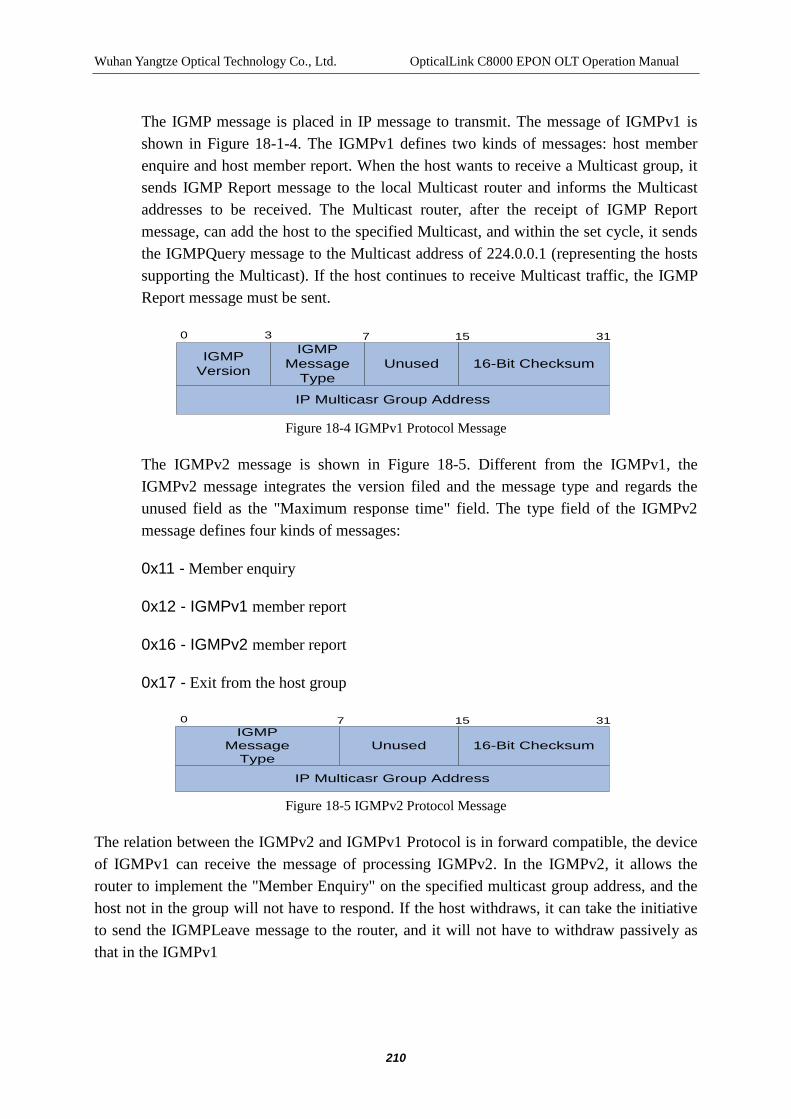
Wuhan Yangtze Optical Technology Co., Ltd. OpticalLink C8000 EPON OLT Operation Manual
210
The IGMP message is placed in IP message to transmit. The message of IGMPv1 is shown in Figure 18-1-4. The IGMPv1 defines two kinds of messages: host member enquire and host member report. When the host wants to receive a Multicast group, it sends IGMP Report message to the local Multicast router and informs the Multicast addresses to be received. The Multicast router, after the receipt of IGMP Report message, can add the host to the specified Multicast, and within the set cycle, it sends the IGMPQuery message to the Multicast address of 224.0.0.1 (representing the hosts supporting the Multicast). If the host continues to receive Multicast traffic, the IGMP Report message must be sent.
IGMPVersion
IGMPMessage
TypeUnused 16-Bit Checksum
IP Multicasr Group Address
0 3 7 15 31
Figure 18-4 IGMPv1 Protocol Message
The IGMPv2 message is shown in Figure 18-5. Different from the IGMPv1, the IGMPv2 message integrates the version filed and the message type and regards the unused field as the "Maximum response time" field. The type field of the IGMPv2 message defines four kinds of messages:
0x11 - Member enquiry
0x12 - IGMPv1 member report
0x16 - IGMPv2 member report
0x17 - Exit from the host group
IGMPMessage
TypeUnused 16-Bit Checksum
IP Multicasr Group Address
0 7 15 31
Figure 18-5 IGMPv2 Protocol Message
The relation between the IGMPv2 and IGMPv1 Protocol is in forward compatible, the device of IGMPv1 can receive the message of processing IGMPv2. In the IGMPv2, it allows the router to implement the "Member Enquiry" on the specified multicast group address, and the host not in the group will not have to respond. If the host withdraws, it can take the initiative to send the IGMPLeave message to the router, and it will not have to withdraw passively as that in the IGMPv1

Wuhan Yangtze Optical Technology Co., Ltd. OpticalLink C8000 EPON OLT Operation Manual
211
18.2 Multicast Configuration
C8000 system is a two-layer switching device with the main component of PON. The controllable Multicast mode must take into account the realization of Multicast protocol and the authority control strategy, the system applies the IGMP proxy and the VLAN for resolving the realization of the Multicast authority control.
18.2.1 Basic Configuration of OLT Multicast
Table 17-3 Basic Configuration of OLT Multicast Item Command Description Enter config view config terminal -
Configure the working mode of IGMP proxy of local terminal
igmp mode (ctc | proxy | diable)
Mandatory ctc : ctc: igmp controllable multicast mode. proxy : igmp proxy mode (non-controlled mode). diable :Disable igmp proxy mode.
Configure the maximum number of Multicast channels allowed by the system
igmp max-groupnum channeled-max
Optional, the default value of the allowable maximum number of Multicast groups is 255.
Restore the default configuration
no igmp max-groupnum
Optional, the default value of the allowable maximum number of Multicast groups is 255.
Configure the aging time of the Multicast router port
igmp router-aging-time seconds
Optional, the default value of the aging time of Multicast router is 105s.
Restore the default configuration
no igmp router-aging-time
Optional, the default value of the aging time of Multicast router is 105s.
Configure the designated port of the Multicast router port
igmp router-port slotid port
Optional, the default router port is all service network interfaces.
Configure the default port of the Multicast router port
no igmp router port Optional, the default router port is all service network interfaces.

Wuhan Yangtze Optical Technology Co., Ltd. OpticalLink C8000 EPON OLT Operation Manual
212
Configure the vlan tag of the igmp report message forwarded to the Service Network Interface
igmp vlantag vid
Optional, after the configuration is effective, the igmp report forwarded to the service network interface carries the vlan tag, and vlanid = vid.
Configure the igmp report without vlan tag forwarded to the Service Network Interface
no igmp vlantag
Optional, after the configuration is effective, the igmp report forwarded to the service network interface does not carry the vlan tag.
Show the parameters on Multicast configured in the current system
show igmp configuration
Optional, check the igmp configuration.
Show the CDR records of the current system
show igmp cdr Optional, when the igmp mode is ctc, record CDR (Call Detail Record) information .
Show the Multicast Address Table of the current system
show igmp addr Optional。
Show all PON port igmp-proxy modes
show pon igmp-proxy mode
Optional, when using the igmp mode command for configuration, configure the igmp mode of all PONs.
Enter pon view interface pon interface-num
Optional, for pon interface, in the form of (<1-6>|<9-14>)/(<1-4>), refers to the number of the port in the numbered slot, such as 11/3.
Show all PON port igmp-proxy modes
show igmp-proxy mode
Optional, when using the igmp mode command for configuration, configure the igmp mode of all PONs.
Show PON port igmp-proxy tables
show igmp-proxy table Optional
18.2.2 Basic Configuration of ONU Multicast
Table 17-4 Basic Configuration of ONU Multicast

Wuhan Yangtze Optical Technology Co., Ltd. OpticalLink C8000 EPON OLT Operation Manual
213
Item Command Description
Enter onu View interface onu interface-num
Mandatory, for onu interface, in the form of(<1-6>|<9-14>)/(<1-4>):(<1-64>) refers to the number of ONU of the numbered PON port in the numbered slot, such as 9/1:31.
Set the igmp snooping state of ONU
igmp-snooping (enable | disable)
Optional, se the igmp snooping state of ONU's (the initial value of enable): enable: on; disable: off
Set the Multicast Protocol of ONU
multicast-protocol (ctc | igmp-snooping)
Mandatory. Set the multicast mode of ONU, ctc: igmp controllable multicast mode; igmp-snooping: igmp-snooping mode.
Set the maximum multicast groups of the port of ONU
port multicast-group-num (all | uniid) maxnum
Optional, set the maximum multicast groups of the port of ONU all: all GE and FE ports of ONU. uniid: GE or FE port number of ONU with the range of 1-26. maxnum: maximum multicast number of the port with the range of 0-80.
Restore the maximum multicast groups of the port of ONU to the default values
no port multicast-group-num
Restore the maximum multicast groups of the port of ONU to the default value of 64.
Set the Multicast tag of the port of ONU to the stripping processing state
port multicast-tag-strip (all | uniid) (enable | disable)
Optional,Set the Multicast tag of the port of ONU to the stripping processing state all:all GE and FE ports of ONU. uniid:GE or FE port number of ONU with the range of 1-26. enable: on; disable: off

Wuhan Yangtze Optical Technology Co., Ltd. OpticalLink C8000 EPON OLT Operation Manual
214
Set the port Multicast Vlan of ONU
port multicast-vlan (all | uniid) (add | delete) vlan-id
Optional,Set the port Multicast Vlan of ONU all:all GE and FE ports of ONU. uniid:GE or FE port number of ONU with the range of 1-26. add: Add Multicast vlan to ONU port. delete: Delete the Multicast vlan to ONU port. vlan-id: Multicast vlan id, with the range of 1-4094.
Show the igmp snooping state of ONU
show igmp-snooping
Optional, show igmp snooping state of ONU
Show the Multicast protocol selected by ONU
show multicast-protocol
Optional,show the Multicast protocol selected by ONU
Show the maximum number of multicast of the port of ONU
show port multicast-group-num (all | uniid)
Optional,Show the maximum number of multicast of the port of ONU all:all GE and FE ports of ONU. uniid:GE or FE port number of ONU with the range of 1-26.
Show the Multicast stripping operational status of the port of ONU
show port multicast-tag-strip (all | uniid)
Optional,Show the Multicast stripping operational status of the port of ONU all:all GE and FE ports of ONU. uniid:GE or FE port number of ONU with the range of 1-26.
Show the Multicast Vlan list of the port of ONU
show port multicast-vlan (all | uniid)
Optional,show the Multicast Vlan list of the port of ONU all:all GE and FE ports of ONU. uniid:GE or FE port number of ONU with the range of 1-26.
Set the state of ONU CATV port
catv port (disable|enable)
Optional,Set the state of ONU CATV port disable:disable ONU's CATV port. enable:enable ONU's CATV port.

Wuhan Yangtze Optical Technology Co., Ltd. OpticalLink C8000 EPON OLT Operation Manual
215
Set the function of DHCP Option 82 of ONU
dhcp-pl(disable|enable)
enable and disable the DHCP Option82 function of ONU. The function can record the address information of dhcp clients and dhcp relay devices to the dhcp servers. Along with other software, the restrictions and billing functions on the dhcp distribution can be achieved. disable:off; enable: on;
18.2.3 igmp proxy Protocol Parameter Configuration
Table 17-5 igmp proxy Protocol Parameter Configuration Item Command Description
Enter config view config terminal - Configure the ip address of proxy host
igmp proxy host-ip ipaddress
Optional, IP address of proxy host, in ABCD, 1.1.1.1. by default.
Configure the interval sending the query packets by the igmp proxy
igmp proxy query interval interval-time
Optional, Configure the interval sending the query packets by the igmp proxy interval-time. with the range of 1s-1000s.
Restore the interval sending the query packet to the default configuration
no igmp proxy query interval
Optional, configure as follows: after the igmp proxy receives the leave packet sent by the member of agroup, the default value of the number of query packets sent by a particular group is 125s.
Configure the interval of igmp proxy allowing the host in query packets.
igmp proxy query response response-time
Optional, configure the igmp proxy in the response-time allowing the host for the response to the query packets. With the range of 1s-25s.
Restore the interval allowing the host in query packets to the
no igmp proxy query response
Optional, configure the igmp proxy in the response-time allowing the host for the response

Wuhan Yangtze Optical Technology Co., Ltd. OpticalLink C8000 EPON OLT Operation Manual
216
default configuration to the query packets to 10s.
Configure the number of the query packets sending by a specific group
igmp proxy lastmember-query count count
Optional, configure as follows: after the igmp proxy receives the leave packet sent by the member of a group, count the number of the query packets sent by a particular group with the range of 1-5.
Restore the number of the query packets sending by a specific group to the default configuration
no igmp proxy lastmember-query count
Optional, configure as follows: after the igmp proxy receives the leave packet sent by the member of agroup, the default value of the number of query packets sent by a particular group is 2.
Configure the interval sending the query packet sending by a specific group
igmp proxy lastmember-query interval last-interval
Optional, configure as follows: after the igmp proxy receives the leave packet sent by the member of a group, the interval (last-interval) of the query packets sent by a particular group with the range of1s-3s.
Restore the interval sending the query packet sending by a specific group to the default configuration
no igmp proxy lastmember-query interval
Optional, configure as follows: after the igmp proxy receives the leave packet sent by the member of a group, the interval of the query packets sent by a particular group is 1s.
Configure the robust variants of igmp proxy
igmp proxy robust-variant robust-variant
Optional, configure the robust variants of the igmp proxy to be robust-variant with the range of 1-5.
Restore the robust variants of igmp proxy to the default configuration
no igmp proxy robust-variant
Optional, configure the robust variants of the igmp proxy to be 2.
18.2.4 igmp Channel Table Configuration
Table17-6 igmp Channel Table Configuration

Wuhan Yangtze Optical Technology Co., Ltd. OpticalLink C8000 EPON OLT Operation Manual
217
Item Command Description Enter config view config terminal -
Add the system multicast address, the Multicast channel can be used to restrict the system in Multicast group address that can be requested.
igmp groupaddr channelid ip-begin ip-end vlan-id description
Mandatory, add the system multicast address, the multicast channel can be used to restrict the system in Multicast group address that can be requested. channelid: channel number, ranging of 1-255. ip-begin: initial ip address of channels, in A.B.C.D ip-end : last ip address of channels, in A.B.C.D vlan-id : corresponding to Multicast vlan id of the channel with the range of 1-4094. Note: channel description (up to 20 bytes) all: all channel numbers.
Delete the system multicast address
no igmp groupaddr (all |channelid)
Optional, empty the Multicast Address Table.
Used to display the multicast channel table configured in the current system
show igmp cgroup Optional。
18.2.5 Configuration of igmp Controllable Multicast Preview Parameter
Table 17-7 Configuration of igmp Controllable Multicast Preview Parameter Item Command Description
Enter config view config terminal -
Configure the number that can be added into the preview access channels when the user is within the preview access cycle.
igmp preview count count
Optional, configure the number that can be added into the preview access channels when the user is within the preview access cycle, with the range of 1-5 and the default value of 2.

Wuhan Yangtze Optical Technology Co., Ltd. OpticalLink C8000 EPON OLT Operation Manual
218
Restore the number that can be added into the preview access channels when the user is within the preview access cycle to the default configuration.
no preview count
Optional, configure the number that can be added into the preview access channels when the user is within the preview access cycle to 2.
Configure a preview access cycle
igmp preview cycle time
Optional, configure a preview access cycle , with the range of 1h-24h and the default value of 24h.
Restore the preview access cycle to the default configuration
no preview cycle Optional, Optional, configure a preview access cycle to 24h.
Configure the duration of the preview interval
igmp preview interval seconds
Optional, Configure the duration of the preview interval with the range of 30s-60s and the default value of 60s.
Restore the duration of the preview interval to the default configuration
no preview interval
Optional, Configure the duration of the preview interval to 60s.
Configure the single preview time of the user, that is, the single time that can receive the channel data after the user sends the application of adding into the preview access channel
igmp preview single-time seconds
Optional, Configure the single preview time of the user, that is, the single time that can receive the channel data after the user sends the application of adding into the preview access channel, with the range of 30s-60s and the default value of 60s.
Restore the single preview time of users to the default configuration
no preview single-time
Optional, Configure the single preview time of the user, that is, the single time that can receive the channel data after the user sends the application of adding into the preview access channel to the default value of 60s.
Used to show the preview parameters configured in the current system
show igmp preview
Optional, show the preview parameters configured in the controllable mode.

Wuhan Yangtze Optical Technology Co., Ltd. OpticalLink C8000 EPON OLT Operation Manual
219
18.2.6 Configuration of igmp Controllable Multicast Authority Table
Table 17-8 Configuration of igmp Controllable Multicast Authority Table Item Command Description
Enter ONU view interface ONU interface-num
Mandatory, for onu interface, in the form of(<1-6>|<9-14>)/(<1-4>):(<1-64>) refers to the number of ONU of the numbered PON port in the numbered slot, such as 9/1:31.
Configure the Multicast authority table entries of the user (corresponding to the port of ONU)
igmp-authority uniid channelid (preview | access | deny)
Igmp controllable mode, mandatory, configure the multicast authority table entries of the user (corresponding to the port of ONU) uniid: ONU's port number, with the range of 1-24 channelid: corresponding to the hannel number configured for the Multicast channel table of the system with the range of 1-255. preview: Preview authority. access: authority. deny: prohibit the access.
Delete the Multicast authority table entries of the user (corresponding to the port of ONU)
no igmp-authority uniid channelid
Optional, delete the authority table entries of the Multicast channel of channelid of the user (corresponding to the portuniid of ONU)
Delete the Multicast authority table entries of the user (corresponding to the port of ONU)
igmp-authority flush uniid
Optional, delete all Multicast authority table entries of the user (corresponding to the portuniid of ONU)
Used to show the Multicast authority table of a user currently
show igmp-authority uniid
Optional, used to show the Multicast authority table of a user currently

Wuhan Yangtze Optical Technology Co., Ltd. OpticalLink C8000 EPON OLT Operation Manual
220
18.2.7 Multicast Vlan Configuration
C8000 system is a two-layer switching device with the main component of PON. The system uses the IGMP proxy and the VLAN for realizing the Multicast.
Table 17-9 Multicast vlan Parameter Configuration Item Comma
nd Description
Enter config view config terminal
-
Enter VLAN View, or the view that is created when the VLAN does not exist
vlan first-id [last-id]
Mandatory, enter VLAN view or create VLAN when the VLAN does not exist and then enter the view. The command supports the creation of VLAN in batch. first-id, last-id: the range of the VLAN creation of 1 ~ 4094. If last-id is not designated, then create the VLAN first-id and enter the view or directly enter the view of the vlan that has already existed.
Delete VLAN individually or in batch
no vlan first-id [last-id]
Optional, Delete VLAN individually or in batch. first-id, last-id: the range of the VLAN creation of 1 ~ 4094. If last-id is not designated, then create the VLAN first-id and enter the view or directly enter the view of the vlan that has already existed.

Wuhan Yangtze Optical Technology Co., Ltd. OpticalLink C8000 EPON OLT Operation Manual
221
Add the specified port to the current VLAN
port interface-number (tagged | untagged)
Mandatory, add the designated port to the current VLAN. interface-num: ge interface, in the form of (<1-6>|<9-14>)/(<1-4>), refers to the number of the port in the numbered slot, such as 11/3. xe interface: with the range of 1-3, indicating the numbered xe interface with the order from the top to the bottom on the switch control unit. 1 for the 10GBASE-R (XFP) optical interface, 2 and 3 for the 10GBASE-CX4 copper interface. tagged;tag is reserved when the packet of the specified VLAN ID is outputted from the port. untagged: tag is stripped when the packet of the specified VLAN ID is outputted from the port.
Delete the specified port from the current VLAN
no port interface-number
Optional, delete the specified port from the current VLAN interface-num: ge interface, in the form of (<1-6>|<9-14>)/(<1-4>), refers to the number of the port in the numbered slot, such as 11/3. xe interface: with the range of 1-3, indicating the numbered xe interface with the order from the top to the bottom on the switch control unit. 1 for the 10GBASE-R (XFP) optical interface, 2 and 3 for the 10GBASE-CX4 copper interface.
18.3 IGMP Controllable Multicast Configuration
The controllable multicast needs to take into account the realization of the multicast protocol and the authority control strategy, requiring the configuration of the multicast channel table and the multicast authority table, and the local terminal needs to follow the specific authority of the authority table to determine whether it needs to forward the multicast data streams to the downlink ONU devices.
18.3.1 Configuration of OLT IGMP Controllable Multicast
The section provides the key configuration procedures of the OLT igmp controllable multicast.

Wuhan Yangtze Optical Technology Co., Ltd. OpticalLink C8000 EPON OLT Operation Manual
222
See section 17.2.1 for the basic configuration of OLT; see section 17.2.3 for the igmp proxy protocol parameter configuration; and see section 17.2.5 for the preview parameters configuration of igmp controllable multicast.
Table 17-10 Configuration of OLT IGMP Controllable Multicast Item Command Description
Step1.Enter config view config terminal
-
Step2. Enable the ctc working mode of the IGMP proxy of local device.
igmp mode ctc
Mandatory。
Step3. Add system multicast channel
igmp groupaddr channelid ip-begin ip-end vlan-id description
Mandatory, add the system multicast address, the multicast channel can be used to restrict the system in Multicast group address that can be requested. channelid: channel number, ranging of 1-255. ip-begin : initial ip address of channels ip-end: last ip address of channels vlan-id:corresponding to Multicast vlan id of the channel with the range of 2-4094. Note: channel description (up to 20 bytes)
Step4. Configure Multicast router port
igmp router-port slotid port
Optional, configure Multicast router port
Step5. Enter VLAN View, or the view that is created when the VLAN does not exist
vlan vlan-id Mandatory, Create VLAN vlan-id, and enter the view. vlan-id:with the range of 2-4094.

Wuhan Yangtze Optical Technology Co., Ltd. OpticalLink C8000 EPON OLT Operation Manual
223
Step6. Add designated Multicast router port to the MulticastVLAN
port interface-number tagged
Mandatory, add the designated Multicast router port to the Multicast VLAN interface-num: ge interface, in the form of (<1-6>|<9-14>)/(<1-4>), refers to the number of the port in the numbered slot, such as 11/3. xe interface: with the range of 1-3, indicating the numbered xe interface with the order from the top to the bottom on the switch control unit. 1 for the 10GBASE-R (XFP) optical interface, 2 and 3 for the 10GBASE-CX4 copper interface. tagged;tag is reserved when the packet of the specified VLAN ID is outputted from the port.
Step7.Enter pon view interface pon interface-num
Mandatory, for the pon interface in the form of (<1-6>|<9-14>)/(<1-4>), refers to the number of the port in the numbered slot, such as 11/3.
Step8. Add port into the specified VLAN that has already existed
port vlan vlan-id untagged
Mandatory , Add port into the specified VLAN that has already existed vlan-id: specified VLAN ID number with the range of 1-4094. untagged: tag is stripped when the packet of the specified VLAN ID is outputted from the port.
18.3.2 ONU IGMP Controllable Multicast Configuration
The section provides the key configuration procedures of the OLT igmp controllable multicast. See section 17.2.2 for the basic configuration of ONU.
Table 17-11 ONU IGMP Controllable Multicast Configuration Item Command Description

Wuhan Yangtze Optical Technology Co., Ltd. OpticalLink C8000 EPON OLT Operation Manual
224
Step1.Enter ONU view
interface ONU interface-num
Mandatory, for onu interface, in the form of(<1-6>|<9-14>)/(<1-4>):(<1-64>) refers to the number of ONU of the numbered PON port in the numbered slot, such as 9/1:31.
Step2. Set the ONU Multicast into the igmp controllable mode.
multicast-protocol ctc
Mandatory. Set the Multicast of ONU to be igmp controllable mode.
Step3. Set the Multicast tag of the port of ONU to the stripping processing state
port multicast-tag-strip uniid) enable
Optional, Set the Multicast tag of the port of ONU to the stripping processing state uniid:GE or FE port number of ONU with the range of 1-26. enable:on;
Step4. Configure the Multicast authority table entries of the user
igmp-authority uniid channelid (preview | access | deny)
Mandatory, configure the Multicast authority table entries of the user; uniid: ONU's port number, with the range of 1-26. Channeled: Multicast channel number with the range of 1-255. preview: Preview authority access: access authority deny: prohibition authority
18.3.3 IGMP Controllable Multicast Configuration Example
Configure to achieve the igmp controllable Multicast function.
18.3.3.1 Network Requirement
In order to achieve the igmp controllable Multicast function of the C8000,it needs to start up the igmp ctc at the terminal device, namely, start up the igmp ctc on the ONU device.
Connect the router port of the C8000 with the router or the Multicast server; start up the Multicast Routing Protocol on the router; connect the ONU port to the user PC and start up the igmp client on PC.

Wuhan Yangtze Optical Technology Co., Ltd. OpticalLink C8000 EPON OLT Operation Manual
225
18.3.3.2 Network Diagram
Figure 18-6 igmp Controllable Multicast Network Topology
18.3.3.3 Configuration Procedure
$ Configure the igmp mode of OLT to the igmp controllable Multicast Mode (igmp ctc)
C8000(config)# igmp mode ctc

Wuhan Yangtze Optical Technology Co., Ltd. OpticalLink C8000 EPON OLT Operation Manual
226
$ Configure 4 Multicast channels, the corresponding VIDs are 4001 ~ 4004
C8000(config) #igmp groupaddr 1 224.1.1.1 224.1.1.1 4001 IPTV1
C8000(config) #igmp groupaddr 2 224.1.1.2 224.1.1.2 4002 IPTV2
C8000(config) #igmp groupaddr 3 224.1.1.3 224.1.1.3 4003 IPTV3
C8000(config) #igmp groupaddr 4 224.1.1.4 224.1.1.4 4004 IPTV4
$ Configure the Multicast router port to be the first port of the slu board of No.6 slot.
C8000(config)# igmp router- port 6 1
$Create vlan4001, and add the router port6/1 to vlan4001, set the mode to the tagged mode.
C8000(config)# vlan 4001
C8000(config-vlan-4001)# port 6/1 tagged
$ Create vlan4002, and add the router port6/1 to vlan4002, set the mode to the tagged mode.
C8000(config)# vlan 4002
C8000(config-vlan-4002)# port 6/1 tagged
$ Create vlan4003, and add the router port6/1 to vlan4003, set the mode to the tagged mode.
C8000(config)# vlan 4003
C8000(config-vlan-4003)# port 6/1 tagged
$ Create vlan4004, and add the router port6/1 to vlan4004, set the mode to the tagged mode.
C8000(config)# vlan 4004
C8000(config-vlan-4004)# port 6/1 tagged
$Create vlan2~4
C8000(config)# vlan 2

Wuhan Yangtze Optical Technology Co., Ltd. OpticalLink C8000 EPON OLT Operation Manual
227
C8000(config-vlan-2)#quit
C8000(config)# vlan 3
C8000(config-vlan-3)#quit
C8000(config)# vlan 4
C8000(config-vlan-4)#quit
$ Enter the PON port of the downlink ONU
C8000(config)#interface pon 12/2
$ Add the PON port to the protocol packet vlan
C8000(config-if-pon-12/2)#port vlan 2 untagged
C8000(config-if-pon-12/2)#port vlan 3 untagged
C8000(config-if-pon-12/2)#port vlan 4 untagged
$Enter ONU View
C8000(config)#interface onu 12/2:1
$ Configure the igmp mode of ONU to ctc
C8000(config-if-onu-12/2:1)#multicast-protocol ctc
$ Configure the authority to the users connected to the four ports of ONU (no adding)
C8000(config-if-onu-12/2:1)#igmp-authority1 1 access
C8000(config-if-onu-12/2:1)#igmp-authority1 2 access
C8000(config-if-onu-12/2:1)#igmp-authority 1 3 preview
C8000(config-if-onu-12/2:1)#igmp-authority 1 4 deny
$ Configure the downlink Multicast data of ONU to be Tag-strip
C8000(config-if-onu-12/2:1)#port multicast-tag-strip 1 enable
Note:
Wuhan Yangtze Optical Technology Co., Ltd. OpticalLink C8000 EPON OLT Operation Manual
228
The igmp mode set only refers to the Multicast working mode of the local C8000 and the default igmp mode of the ONU is igmp snooping.
The router port set must be on the SLU plate, otherwise, the configuration will fail. If the expect black deleted has been provided with the router port of the SLU plate, after it is deleted, the router port configuration will be cleared and all service network interfaces will be restored into the router port by default.
Under the igmp controllable mode, the distinction between users (the corresponding ONU port) uses the VLAN tag of the uplink igmp protocol packet (generally vid 1 refers to port 1, vid 2 refers to port 2, and so forth). When the ONU is set to be multicast-protocol ctc, it will add the valn tag independently in accordance with the inputted port of the packet, and the configuration relevant to the vlan on the port of ONU is not needed.
Under the igmp controllable mode, the distinction between users (the corresponding ONU port) uses the VLAN tag of the uplink igmp protocol packet. In order to forward the uplink igmp protocol packet in the main switcher, it needs to add the corresponding PON port (BCM Terminal) into the VLAN filed representing the ONU port.
All PONs belong to vlan 1 of untagged type. Therefore, if the user is connected to the ONU uniid = 1, the default vlan configuration can be used to transmit the uplink IGMP protocol packets.
When the OLT receives the igmp join message sent by the ONU connected and passes through the permission inspection, the PON port connected with the ONU will be automatically added into the MulticastVlan.
After the ONU restarts, the igmp snooping function ten is enabled, at this time, the multicast-protocol command can be used to switch between igmp snooping and igmp ctc.
If the igmp snooping function is disabled, the multicast-protocol igmp-snooping can only set the igmp mode into the igmp snooping, but it cannot enable the igmp snooping.
See 17.2.2 for the ONU igmp snooping state enable switch.
Select the igmp of ONU to be CTC controllable mode, so as to forbid the igmp snooping function of ONU.
The user’s default permission (ie, no configuration permission for a channel) is “DENY".

Wuhan Yangtze Optical Technology Co., Ltd. OpticalLink C8000 EPON OLT Operation Manual
229
18.4 IGMP Proxy Multicast Configuration
The igmp proxy multicast needs to consider the realization of Multicast protocol, needs to configure the Multicast Channel Table, opens the enable state of the igmp proxy of the local device and the enable state of igmp snooping of the ONU.
18.5 OLT IGMP Proxy Multicast Configuration
The section provides the key configuration procedures of the OLT igm pproxy Multicast. See section 17.2.1 for the basic configuration of OLT and See section 17.2.3 for the igmp proxy protocol parameter configuration.
Table 17-12 OLT igmp proxy Multicast Configuration Item Command Description
Step1.Enter config view
config terminal -
Step2. Enable the proxy working mode of the IGMP proxy of local device.
igmp mode proxy Mandatory。
Step3. Add system multicast channel
igmp groupaddr channelid ip-begin ip-end vlan-id description
Mandatory, add the system multicast address, the multicast channel can be used to restrict the system in Multicast group address that can be requested. channelid: channel number, ranging of 1-255. ip-begin : initial ip address of channels ip-end: last ip address of channels vlan-id:corresponding to Multicast vlan id of the channel with the range of 2-4094. Note: channel description (up to 20 bytes)
Step4. Configure Multicast router port
igmp router-port slotid port
Optional, configure Multicast router port

Wuhan Yangtze Optical Technology Co., Ltd. OpticalLink C8000 EPON OLT Operation Manual
230
Step5. Enter VLAN View, or the view that is created when the VLAN does not exist
vlan vlan-id Mandatory, Create VLAN vlan-id, and enter the view. vlan-id:with the range of 2-4094.
Step6. Add Multicast router port to the MulticastVLAN
port interface-number tagged
Mandatory, add the designated Multicast router port to the Multicast VLAN interface-num: ge interface, in the form of (<1-6>|<9-14>)/(<1-4>), refers to the number of the port in the numbered slot, such as 11/3. xe interface: with the range of 1-3, indicating the numbered xe interface with the order from the top to the bottom on the switch control unit. 1 for the 10GBASE-R (XFP) optical interface, 2 and 3 for the 10GBASE-CX4 copper interface. tagged;tag is reserved when the packet of the specified VLAN ID is outputted from the port.
18.5.1 ONU IGMP Proxy Multicast Configuration
The section provides the key configuration procedures of the OLT igmp proxymulticast. See section 17.2.2 for the basic configuration of ONU.
Table 17-13 ONU IGMP Proxy Multicast Configuration Item Command Description
Step1.Enter ONU view
interface ONU interface-num
Mandatory, for onu interface, in the form of(<1-6>|<9-14>)/(<1-4>):(<1-64>) refers to the number of ONU of the numbered PON port in the numbered slot, such as 9/1:31.
Step2. Set the Multicast protocol of ONU
multicast-protocol igmp-snooping
Mandatory. Set the Multicast mode of ONU igmp-snooping:igmp-snooping mode

Wuhan Yangtze Optical Technology Co., Ltd. OpticalLink C8000 EPON OLT Operation Manual
231
Step3. Set the Multicast tag of the port of ONU to the stripping processing state
port multicast-tag-strip (all | uniid) (enable | disable)
Optional, Set the Multicast tag of the port of ONU to the stripping processing state all: GE and FE port numbers of ONU. uniid:GE or FE port number of ONU with the range of 1-26. enable:on; disable: off
Set the Multicast Vlan for the port of ONU
port multicast-vlan (all | uniid) (add | delete) vlan-id
Optional, Set the Multicast Vlan for the port of ONU all:GE and FE port numbers of ONU. uniid:GE or FE port number of ONU with the range of 1-26. add:add Multicast vlanto ONU port. delete:delete Multicast vlanto ONUport. vlan-id:Multicast vlan id, with the range of <1-4094>.
18.5.2 IGMP Proxy Multicast Configuration Example
Configure to realize the igmp proxy multicast function.
18.5.2.1 Network Requirement
To achieve the igmp proxy Multicast function of the C8000, it needs to start up the igmp proxy on the local device and start up the igmp snooping on the ONU device.
Connect the router port of the C8000 with the router or Multicast server, start up the Multicast Routing Protocol on the router, connect the ONU port to user PC, and start up the igmp client on PC.

Wuhan Yangtze Optical Technology Co., Ltd. OpticalLink C8000 EPON OLT Operation Manual
232
18.5.2.2 Network Diagram
Figure 17-7 igmp proxy Multicast Network Topology
18.5.2.3 Configuration Procedure
$ Configure the igmp mode of OLT to the igmp proxy Multicast Mode
C8000(config)# igmp mode proxy
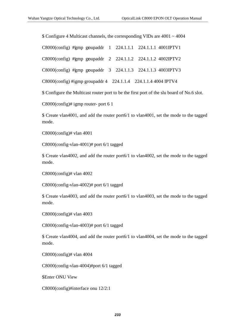
Wuhan Yangtze Optical Technology Co., Ltd. OpticalLink C8000 EPON OLT Operation Manual
233
$ Configure 4 Multicast channels, the corresponding VIDs are 4001 ~ 4004
C8000(config) #igmp groupaddr 1 224.1.1.1 224.1.1.1 4001 IPTV1
C8000(config) #igmp groupaddr 2 224.1.1.2 224.1.1.2 4002 IPTV2
C8000(config) #igmp groupaddr 3 224.1.1.3 224.1.1.3 4003 IPTV3
C8000(config) #igmp groupaddr 4 224.1.1.4 224.1.1.4 4004 IPTV4
$ Configure the Multicast router port to be the first port of the slu board of No.6 slot.
C8000(config)# igmp router- port 6 1
$ Create vlan4001, and add the router port6/1 to vlan4001, set the mode to the tagged mode.
C8000(config)# vlan 4001
C8000(config-vlan-4001)# port 6/1 tagged
$ Create vlan4002, and add the router port6/1 to vlan4002, set the mode to the tagged mode.
C8000(config)# vlan 4002
C8000(config-vlan-4002)# port 6/1 tagged
$ Create vlan4003, and add the router port6/1 to vlan4003, set the mode to the tagged mode.
C8000(config)# vlan 4003
C8000(config-vlan-4003)# port 6/1 tagged
$ Create vlan4004, and add the router port6/1 to vlan4004, set the mode to the tagged mode.
C8000(config)# vlan 4004
C8000(config-vlan-4004)#port 6/1 tagged
$Enter ONU View
C8000(config)#interface onu 12/2:1

Wuhan Yangtze Optical Technology Co., Ltd. OpticalLink C8000 EPON OLT Operation Manual
234
$ Configure the igmp mode of ONU to igmp-snooping
C8000(config-if-onu-12/2:1)#multicast-protocol igmp-snooping
$ Configure ONU Multicast vlan
C8000(config-if-onu-12/2:1)#port multicast-vlan 1 add 4001
C8000(config-if-onu-12/2:1)#port multicast-vlan 2 add 4002
C8000(config-if-onu-12/2:1)#port multicast-vlan 3 add 4003
C8000(config-if-onu-12/2:1)#port multicast-vlan 4 add 4004
$ Configure downlink Multicast data of ONU to be Tag-strip
C8000(config-if-onu-12/2:1)#port multicast-tag-strip 1 enable
Note:
The igmp mode set only refers to the Multicast working mode of local C8000 and the default igmp mode of the ONU is igmp snooping.
The router port set must be on the SLU plate, otherwise, the configuration will fail. If the expected SLU plate deleted has been provided with the router port, after it is deleted, the router port configuration will be cleared and all service network interfaces will be restored into the router port by default.
When the OLT receives the igmp join message sent by the downlink ONU, the PON port connected with the ONU will be automatically added into the Multicast Vlan.
After the ONU restarts, the igmp snooping function ten is enabled, at this time, the multicast-protocol command can be used to switch between igmp snooping and igmp ctc.
If the igmp snooping function is disabled, the multicast-protocol igmp-snooping can only set the igmp mode into the igmp snooping, but it cannot enable the igmp snooping.
See 17.2.2 for the ONU igmp snooping state enable switch.
The user’s default permission (ie, no configuration permission for a channel) is “DENY".

235
19 PERFORMANCE CONFIGURATION MANAGEMENT
19.1 Introduction to Performance Configuration
The device can realize the statistics and records on the data received/sent by each port of the OLT, the user can check the statistical information on the network data of each port of the OLT by command line and network management to facilitate the optimization of network and equipment and the problem diagnosis.
The data in performance statistics contains two kinds: present 15-minute performance statistics and historic 15-minute performance statistics. The number of performance data contained in each port is as follows: 1 for present 15-minute performance statistics and 192 for historic 15-minute performance statistics. The statistical items of the OLT performance statistics data are as follows:
Table 19-1 of Performance Data Statistics
No. Statistics Items of OLT Terminal Performance
1 Number of Octets of the Receiving Terminal of the Port
2 Number of Packets of the Receiving Terminal of the Port
3 Number of Unicast Packets of the Receiving Terminal of the Port
4 Number of Multicast Packets of the Receiving Terminal of the Port
5 Number of Broadcast Packets of the Receiving Terminal of the Port
6 Number of Discards Packets of the Receiving Terminal of the Port
7 Number of Errors Packets of the Receiving Terminal of the Port

Wuhan Yangtze Optical Technology Co., Ltd. OpticalLink C8000 EPON OLT Operation Manual
236
8 Number of Undersize Packets of the Receiving Terminal of the Port
9 Number of Oversize Packets of the Receiving Terminal of the Port
10 Number of Unknown Protocols Packets of the Receiving Terminal of the Port
11 Number of CRC Errors Packets of the Receiving Terminal of the Port
12 Number of Octets of the Transmitting Terminal of the Port
13 Number of Frames of the Transmitting Terminal of the Port
14 Number of Unicast Packets of the Transmitting Terminal of the Port
15 Number of Multicast Packets of the Transmitting Terminal of the Port
16 Number of Broadcast Packets of the Transmitting Terminal of the Port
The sample time of the device performance data of the OLT is configurable; the performance data can be collected once every sample time. The present 15-minute performance statistics and the historic 15-minute performance statistics need to be updated every 15 minutes.
19.2 Performance Configuration
19.2.1 OLT Performance Configuration
Table 18-2 OLT Performance Enable/Disable/Clear/Display

Wuhan Yangtze Optical Technology Co., Ltd. OpticalLink C8000 EPON OLT Operation Manual
237
Item Command Description
Enter config View config terminal -
Enter port View interface gigabit-ethernet
interface-num
interface pon interface-num
interface x-ethernet (xe1|xe2|xe3)
-
Enable performance switch
perf enable
Disable performance switch
perf disable
Clear the performance data of current 15 minutes
and current 24 hours
perf clear Only when the performance
switch is enabled, the command can be effective
Show the historical15-minute performance data
show perf history15 [counts]
Only when the performance switch is enabled, the historical 15-minute data can be saved and the historical data can be shown.
Show the performance data of current 15 minutes/current 24 hours/historical 24 hours
show perf (current15 | current24 | history24)
Only when the performance switch is enabled, the performance data can be saved and shown.
Table 18-3 Basic Configuration of OLT Performance Item Command Description Enter config View config terminal -

Wuhan Yangtze Optical Technology Co., Ltd. OpticalLink C8000 EPON OLT Operation Manual
238
Configure the OLT performance acquisition time
perf olt sample-time seconds
Optional The default of the OLT performance acquisition time is 30s.
Configure the OLT performance threshold
perf (uplink | pon) threshold OutDis-th OutErr-th InDis-th InDis-th InDis-th
Optional The default values of output packet loss, output error packet, inputted packet loss, inputted error packet and inputted CRC error packets are 20000
Show the performance configuration information
show perf config Show the configuration information of OLT and ONU
19.2.2 ONU Performance Configuration
Table 18-4 ONU Performance Enable/Disable/Clear/Display Item Command Description Enter config View config terminal - Enter onu View interface onu interface-number interface-numberrefers to
the ONU number Enable performance switch
perf enable
Disable performance switch
perf disable
Clear the performance data of current 15 minutes and current 24 hours
perf clear
Only when the performance switch is enabled, the command can be effective
Show the historical15-minute performance data
show perf history15 [counts]
Only when the performance switch is enabled, the historical 15-minute data can be saved and the historical data can be shown.

Wuhan Yangtze Optical Technology Co., Ltd. OpticalLink C8000 EPON OLT Operation Manual
239
Show the performance data of current 15 minutes/current 24 hours/historical 24 hours
show perf (current15 | current24 | history24)
Only when the performance switch is enabled, the performance data can be saved and shown.
Table 18-5 Basic Configuration of ONU Performance Item Command Description Enter config View config terminal -
Configure the ONU performance acquisition time
perf onu sample-time seconds
Optional The default of the ONU performance acquisition time is 30s.
Configure the ONU performance threshold
perf (onupon | onuuni) threshold OutCRC-th InBad-th InCRC-th
Optional The default values of outputted CRC error frames, total inputted error bytes and inputted CRC32 checksum error of ONU are 20000.
Show the performance configuration information
show perf config Show the configuration information of OLT and ONU
Configure the system time of onu
perf onu time systime
Optional Configure the system time of ONU and systime refers to the system time
19.3 Performance Configuration Example
19.3.1 Network Requirement
Enable the performance switch of pon 3/1 and show the performance data.

Wuhan Yangtze Optical Technology Co., Ltd. OpticalLink C8000 EPON OLT Operation Manual
240
19.3.2 Network Diagram
PON3/1 GE10/1ONU
Figure 18-1 Performance Configuration Example
19.3.3 Configuration Procedure
C8000(config)# interface pon 3/1
C8000(config-if-pon-3/1)# perf enable
C8000(config-if-pon-3/1)# show perf current15
C8000(config-if-pon-3/1)# show perf current24
C8000(config-if-pon-3/1)# show perf history24
C8000(config-if-pon-3/1)# show perf history15

241
20 ALARM CONFIGURATION MANAGEMENT
20.1 Introduction to Alarm Configuration
After enabling the alarm, if the system has errors or implements some important operations, the OLT alarm event will be triggered, and then the OLT will save the alarm information into the alarm buffer. By the show alarm active or show alarm history command, the current active alarm and the historical alarm of the system can be checked. All alarm information can be sent to the server by the snmp trap and can also be shielded.
The alarm is the notice of the system when it detects failure, including failure alarm and recovery alarm, of which, the failure alarm lasts until the failure is corrected. Not every alarm has the alarm recovery.
The event is the notice generated under normal operation and taking the initiative to prompt the user, including running event and security event. The difference between event and alarms is that: the alarm is the notice reported when the system is abnormal or when the exceptional circumstances may happen, while the event is the notice reported when the system is normal.
Without special remarks, the alarm includes the alarm and the event.
Under the default configuration, all alarms can be automatically printed in the user interface.
20.2 Introduction to Alarm Configuration Task
Table 19-1 Alarm Configuration Tasks
Configuration Tasks Description Detailed Configuration
Configure snmp trap server
Optional See section 19.3
Configure Alarmtrap shield
Optional See section 19.4

Wuhan Yangtze Optical Technology Co., Ltd. OpticalLink C8000 EPON OLT Operation Manual
242
20.3 Configure snmp trap Server
Prerequisites
Before the configuration, connect the server with OLT Outband network management port and set the IP addresses of OLT Outband and server into the same network segment.
Configure snmp trap server
Table 19-2 Configure snmp trap Server
Item Command Description
Enter config View config terminal
Configure snmp trap Server
snmp trap server community (v1 | v2c) ipaddress
Configure the group name, IP address and version number of snmp trap server
Note:
You can configure multiple snmp trap servers, C8000 support a maximum of eight servers.
20.4 Configure Alarm Information Shield
Prerequisites
Before configuring, bind the authorization of ONU. See Chapter 10 ONU Configuration Management for the specific operation.
The configuration items of all alarm information are shown in the following table.
Table 19-3 Alarm Configuration Items
Item Command Description
Shield the Alarm TRAP alarm trap slot slotid After the alarm TRAP of the

Wuhan Yangtze Optical Technology Co., Ltd. OpticalLink C8000 EPON OLT Operation Manual
243
of a slot (config View) (enable | disable) slot is shielded, any alarms of the slot cannot send the TRAP messages
Shield the specified Alarm TRAP (config View)
alarm trap alarmid alarmid (enable | disable)
After the TRAP of the specified Alarm ID is shielded, the alarm will not send any TRAP messages
Shield the Alarm TRAP of PON port (pon View)
trap (enable | disable) After the alarm TRAP of the PON port is shielded, any alarms of the PON port cannot send the TRAP messages
Shield the Alarm TRAP of ONU port (onu View)
trap (enable | disable) After the alarm TRAP of the ONU port is shielded, any alarms of the ONU port cannot send the TRAP messages
Clear active or historical alarm information (config View)
no alarm (active | history) (alarmid | all)
Clear the active and historical alarm message of the specified alarm ID
Clear all active and historical alarm messages
20.5 Alarm Configuration Example
Network Requirement
Configure the SNMP server and shield all alarm information of No.1 PON port of LPU4 board of No. 4# slot.
Configuration Procedure
If the OLT is connected with snmp server (Both Inband and Outband are OK), as shown in the figure, the IP address of the OLT and the IP address of snmp server must be in the same network segment.

Wuhan Yangtze Optical Technology Co., Ltd. OpticalLink C8000 EPON OLT Operation Manual
244
Figure 19-1 Alarm Configuration Topology
$Enter config mode
C8000#config terminal
$ Configure the SNMP group attribute to public, the version to v2c and the server address to 192.168.7.111.
C8000(config)#snmp trap server public v2c 192.168.7.111
$Enter PON 4/1interface mode
C8000(config)#interface pon 4/1
$ Disable all alarm TRAPs of the PON
C8000(config-if-pon-4/1)#alarm trap disable
20.6 Alarm Configuration Display and Maintenance
Table 19-4 Alarm Configuration Display and Maintenance

Wuhan Yangtze Optical Technology Co., Ltd. OpticalLink C8000 EPON OLT Operation Manual
245
Item Command Description
Enter enable View enable
Show SNMP TRAP server configuration information
show snmp trap server Show SNMP TRAP server configuration information
Show alarm configuration information
show alarm config Show the alarm TRAP shielding information of the system
21 NETWORK MANAGEMENT CONFIGURATION
21.1 Introduction to Network Management Mode
C8000 OLT device supports the access control of three management means at the same time:
Table 20-1 C8000 Network Management Approach Management
Approach Protocol Description
Console port control CLI The serial port supports the CLI management approach
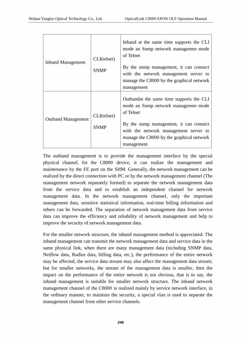
Wuhan Yangtze Optical Technology Co., Ltd. OpticalLink C8000 EPON OLT Operation Manual
246
Inband Management CLI(telnet)
SNMP
Inband at the same time supports the CLI mode an Snmp network managemen mode of Telnet
By the snmp management, it can connect with the network management server to manage the C8000 by the graphical network management
Outband Management CLI(telnet)
SNMP
Outbandat the same time supports the CLI mode an Snmp network managemen mode of Telnet
By the snmp management, it can connect with the network management server to manage the C8000 by the graphical network management
The outband management is to provide the management interface by the special physical channel, for the C8000 device, it can realize the management and maintenance by the FE port on the SHM. Generally, the network management can be realized by the direct connection with PC or by the network management channel (The management network separately formed) to separate the network management data from the service data and to establish an independent channel for network management data. In the network management channel, only the important management data, sensitive statistical information, real-time billing information and others can be forwarded. The separation of network management data from service data can improve the efficiency and reliability of network management and help to improve the security of network management data.
For the smaller network structure, the inband management method is appreciated. The inband management can transmit the network management data and service data in the same physical link, when there are many management data (including SNMP data, Netflow data, Radius data, billing data, etc.), the performance of the entire network may be affected, the service data stream may also affect the management data stream; but for smaller networks, the stream of the management data is smaller, then the impact on the performance of the entire network is not obvious, that is to say, the inband management is suitable for smaller network structure. The inband network management channel of the C8000 is realized mainly by service network interface, in the ordinary manner, to maintain the security, a special vlan is used to separate the management channel from other service channels.

Wuhan Yangtze Optical Technology Co., Ltd. OpticalLink C8000 EPON OLT Operation Manual
247
Note:
For the same gateway, the IP address of the inband cannot be in the same network segment to the IP address of the outband.
Table 20-2 Configuration Command Relevant to the Network Management Item Command Description
Create 、Enter vlan View
vlan first-id [last-id] no vlan first-id [last-id]
first-id, last-id: the range of the VLAN creation of 1 ~ 4094. If last-id is not designated, then create the VLAN first-id and enter the view or directly enter the view of the vlan that has already existed.
Configure the inband network management IP address
inband ip-address ip-address netmask mac-address no inband ip-address
ip-address: Inband network management interface IP address, in dotted-decimal format
netmask: corresponding subnet mask, in dotted-decimal format mac-address: hardware address of Inband network management interface: 00:00:01:03:04: AB
Back to the configured Outband IP address of gateway in the config view
outband ip-address ipaddress nemask
ipaddress: ip address, in A.B.C.D
nemask: subnet mask, in A.B.C.D
Configure the inband gateway IP address
gateway ipaddress no gateway show gateway
The default gateway address of the system, in A.B.C.D

Wuhan Yangtze Optical Technology Co., Ltd. OpticalLink C8000 EPON OLT Operation Manual
248
Figure 20-1Management Network Diagram
21.2 Default Network Management Configuration
When the OLT device of C8000 is not in the same network segment to the network gateway server, that is to say, when the equipment maintenance needs to cover different network segments, the gateway setup must be made. The role of the default gateway is that when C8000 devices are not in a network segment, all data will be forwarded to the default gateway and then will be forwarded by the default gateway.
Configure the default gateway
C8000(config)# gateway 10.10.2.1
C8000(config)# show gateway
%Gateway:10.10.2.1.
C8000(config)#

Wuhan Yangtze Optical Technology Co., Ltd. OpticalLink C8000 EPON OLT Operation Manual
249
Note:
After the completion of default gateway configuration, no modification is allowed. For the modification, it needs to use the no gateway command to delete the default gateway and then use the gateway command for adding.
At the time when configuring the default gateway, it needs to ensure the IP address of the default gateway is in the same network segment to the local outband or inband IP addresses.
21.3 Outband Network Management Configuration
The configuration of the outband network only requires the configuration of IP address and subnet mask.
The configuration of the IP address of the outband network management is as follows:
C8000(config)# outband ip-address 10.10.1.100 255.255.0.0
Note:
After the completion of the IP address of the outband gateway, it needs to connect the FE port of the C8000 with the PC by a direct cable, and to use the ping mode to check whether the network port is normal.
21.4 Inband Network Management Configuration
The C8000 device provides the function of inband network management by the service network interface or the ONU connected with the PON port, which requires the configuration of IP address, subnet mask, mac address and items relevant to vlan.
Step I: Create the VLAN for inband network management to 1000
C8000(config)#vlan 1000
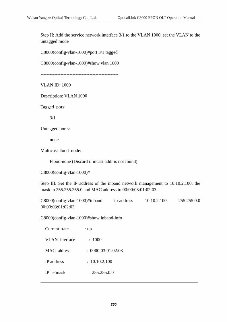
Wuhan Yangtze Optical Technology Co., Ltd. OpticalLink C8000 EPON OLT Operation Manual
250
Step II: Add the service network interface 3/1 to the VLAN 1000, set the VLAN to the untagged mode
C8000(config-vlan-1000)#port 3/1 tagged
C8000(config-vlan-1000)#show vlan 1000
---------------------------------------------------
VLAN ID: 1000
Description: VLAN 1000
Tagged ports:
3/1
Untagged ports:
none
Multicast flood mode:
Flood-none (Discard if mcast addr is not found)
C8000(config-vlan-1000)#
Step III: Set the IP address of the inband network management to 10.10.2.100, the mask to 255.255.255.0 and MAC address to 00:00:03:01:02:03
C8000(config-vlan-1000)#inband ip-address 10.10.2.100 255.255.0.0 00:00:03:01:02:03
C8000(config-vlan-1000)#show inband-info
Current state : up
VLAN interface : 1000
MAC address : 00:00:03:01:02:03
IP address : 10.10.2.100
IP netmask : 255.255.0.0

Wuhan Yangtze Optical Technology Co., Ltd. OpticalLink C8000 EPON OLT Operation Manual
251
Note:
Ensure the VLAN of the inband management channel is separated from the service VLAN to prevent the service broadcast data from entering the CPU of SCU.
In configuring the MAC address of the inband network management, more attention should be paid to configuing the MAC address into the MAC address of Multicast.