Embed Size (px)
Citation preview

Optical zoom system for target projection
Item Type text; Thesis-Reproduction (electronic)
Authors Anderson, Ronald Colbert, 1933-
Publisher The University of Arizona.
Rights Copyright © is held by the author. Digital access to this materialis made possible by the University Libraries, University of Arizona.Further transmission, reproduction or presentation (such aspublic display or performance) of protected items is prohibitedexcept with permission of the author.
Download date 26/06/2018 03:15:06
Link to Item http://hdl.handle.net/10150/554580
OPTICAL ZOOM SYSTEM FOR TARGETPROJECTION
byRonald Colbert Anderson
A Thesis Submitted to the Faculty of theCOMMITTEE ON OPTICAL - SCIENCES
In Partial Fulfillment of the Requirements For the Degree ofMASTER OF SCIENCE
In the Graduate CollegeTHE UNIVERSITY OF ARIZONA
1 9 7 3
STATEMENT BY AUTHOR
This thesis has been submitted in partial fulfillment of requirements for an advanced degree at The University of Arizona and is deposited in the University Library to be made available to borrowers under rules of the Library.
Brief quotations from this thesis are allowable without special permission, provided that accurate acknowledgment of source is made. Requests for permission for extended quotation from or reproduction of this manuscript in whole or in part may be granted by the head of the major department or the Dean of the Graduate College when in his judgment the proposed use of the material is in the interests of scholarship. In all other instances, however, permission must be obtained from the author.
SIGNE
APPROVAL BY THESIS DIRECTOR This thesis has been approved on the date shown below:
SACK D. GASKILL ' " DateAssociate Professor of Optical Science
PREFACE
The subject of this thesis is the design, fabrication, and testing of the electro-optical target projector portion of the SIMFAX Flight Simulation Facility, which was designed and built by Hughes Aircraft Company to evaluate missile flight hardware during development and pre-flight testing.
The facility has four major divisions: (1) A flighttable, with three degrees of freedom, which exposes the missile hardware to launch transients, attitude, and attitude or precession rates, and the effects of aircraft flow fields; (2) an electro-optical target image projectorwhich provides a selected, dynamic target during the simulated flight; (3) peripheral equipment to provide formissile signal conditioning and the control and display of missile performance data; and (4) a hybrid computer to close missile-target geometry loops and to compute equations of motion, aerodynamic forces and moments, and gust disturbances.
In addition to computer operation, the target projector could be operated independently by internal analog signals which would vary the target size inversely with missile-to-target range. The scope of this thesis is limited to the latter mode of operation.
iii
ivThe nature of a project as large as SIMFAX is that
the job is accomplished by a team of people. Although the author was the engineer responsible for the design and fabrication of the target projector, many persons contributed toward the final success of the project. In order that proper credit be given, the following list of acknowledgments has been prepared. The persons are all employees of Hughes Aircraft Company, and unless otherwise stated, worked under the guidance and direction of the author.
1. Dr. Arthur Schneider was technical director of the entire SIMFAX project, and he capably interpreted the system requirements into realistic design objectives for the target projector.
2. Donald J. Strittmatter was the author's supervisor and gave invaluable guidance during the formulation of the design. His technical assistance was instrumental in the successful completion of the project.
3. Thomas Cargen and Dean Tebo were co-designers of the target projector and they were responsible for the design and fabrication of the servo system and its electronic controls.
4. Dean Sinclair designed the target source electronics.5. Arthur Thompson was responsible for the mechanical
hardware of the target projector.6. William Biggs was responsible for drawings and much t
of the mechanical design.
7„ Ellis Romer performed the majority of the optical assembly and checkout.
8. Howard Morrow (summer employee and University of Arizona student) contributed significantly to the mechanization of producing the target slides in large quantities.
9. Jess Jackson and Jim Keihner coordinated the field work concerned with facilities and procedures for taking target negatives.
10. Jim Dell was the photographer who prepared the target negatives.
11. A1 Lange was in charge of the completed facility and was instrumental in establishing the computer interfaces.
12. Robert Peterson performed an evaluation of the - dynamic servo characteristics of the target projector.
TABLE OF CONTENTS
PageLIST OF ILLUSTRATIONS „ „ „ . » „ „ . „ . ... . . . . . viiiLIST OF TABLES O O e o o . o b o o o o o o o o o o o o o 1 2C
ST C o o o o o o o o o e o 6 o o o o o o o o ® - o o 2C
CHAPTER1. INTRODUCTION . ' 1
Functional Approach o'<.«o.. . . . . . . . 2Zoom Requirements . . . . . . . . . . . . . . 3Optical Requirements . . . . . . . . . . . . 3Image Transfer Requirements . . . . . . . . 4Scope of Thesis . . . . . . . . . . . . . . . . 5
2-. PHYSICAL DESCRIPTION . . . . . . . . . . . . . . . 7Functional Description . . . . . . . . . . . 7
lit Ij Cj rx5 5 . . .-. . . . . . . ... . . 7Optical Configuration . . . . . . . . . 9Geometric Properties . . . . . . . . . . . 12Additional Features . . . . . . . . . . 14
Operational Description . . . . . . . . . . 15Control Console Functions . . . . . . . 15Setup for Automatic Mode . . . . . . . . 17
3. OPTICAL DESIGN . . . . . . . . . . . . . . . . . 19Major Optical Components . . . . . . . . . . 19
Zoom Lens 19Close-Up Lens . . . . . . . . . . . . . 21Lens Examination . . . . . . . . . . . . 21Collimating Lens . . . . . . . . . . . . 24S1 id e S i z e . . . . . . . . . . . . . . . 2 7System Analysis . . . . . . . . . . . . 28
Source Requirements . . . . . . . . . . . . 31Source Selection v 32Source Controls . . . . . . . . . . . . . 34Miscellaneous Features . . . . . . . . . 37
Target Slide Production . . . . . . . . . . 39Resolution Requirements . . . . . . . . 41Slide Production . . . . . . . . . . . . 46
vi
TABLE OF CONTENTS— ContinuedPage
4o TARGET PROJECTOR PERFORMANCE . * . . . . . . . . 50Zoom Requirements e » o « 0 » o o » » » » » 50
Static Calibration o o ® o ® o"oo » » o 50Dynamic Calibration • o • • o' '•••..’ » 51
Optical Requirements 0 » o 'o • o .. o • • • • o 51Projected Angular Field 0 «, » » o « «> » 51E XjL t Pupi 1 o o o o o o o o o e o o e © o 52Resolution o o o © © © © © © © © © © © © 52Luminance © © o © © © © © © © o © © © © 5 3Uniformity © o © © © o © © © © © © © © © 53
Image Transfer © © © © © © © © © © © © © © © 54Conclusion. © © © © © © © © © © © © © © © © © 54
APPENDIX A© SOURCE RADIANCE © © © © © © © © © © © © © 56REFERENCES © © © © © © © © o © © © © © © © © © © @ © @ 61
LIST OF ILLUSTRATIONS
Figure Page1. Plan View of Target Projector » 82. Major Optical Components of a Single Zoom
Ii e ns S s t em » o o « o @ o o « * o # o ® ® o o 11/ ■ -
3. Geometric Properties of a Single ZoomL e ns S f S *t C 111 o e o e o o o o e » o o o o o o 6 1 3
4. Projector System Elements Which Effect theDiameter of the System Exit Pupil „ „ „ » » » * 25
5. Source Intensity Waveform = . = 366» Slide Resolution 427„ Normalized Spectral Functions . . . . . . . . . . 58
viii
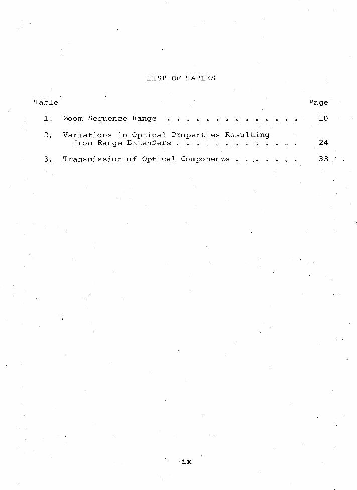
LIST OF TABLES
Table Page1„ Zoom Sequence Range „ » » . , . „ . . . . . . . . 102. Variations in Optical Properties Resulting
from Range Extenders . . . e . 24.3. Transmission of Optical Components . . . . . . . 33
ix
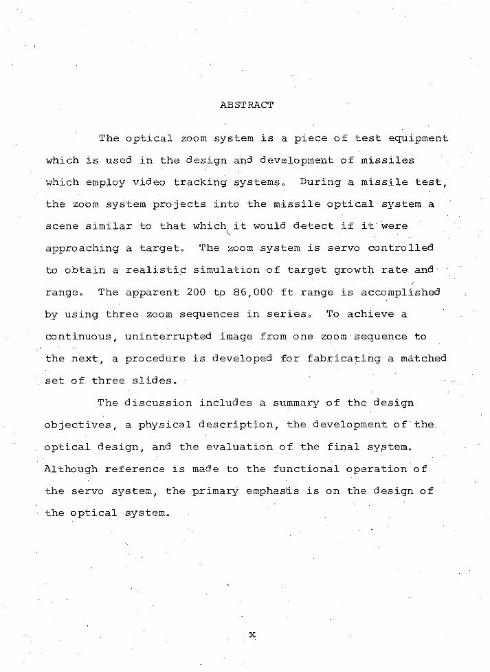
ABSTRACT
The optical zoom system is a piece of test equipment which is used in the design and development of missiles which employ video tracking systems. During a missile test, the zoom system projects into the missile optical system a scene similar to that which it would detect if it were
V. .
approaching a target. The zoom system is servo controlled to obtain a realistic simulation of target growth rate and range. The apparent 200 tp 86,000 ft range is accomplished by using three zoom sequences in series. To achieve a continuous, uninterrupted image from one zoom sequence to the next, a procedure is developed for fabricating a matched set of three slides.
The discussion includes a summary of the design objectives, a physical description, the development of the. optical design, and the evaluation of the final system. Although reference is made to the functional operation of the servo system, the primary emphaslis is on the. design of the optical system.
x
CHAPTER 1
INTRODUCTION
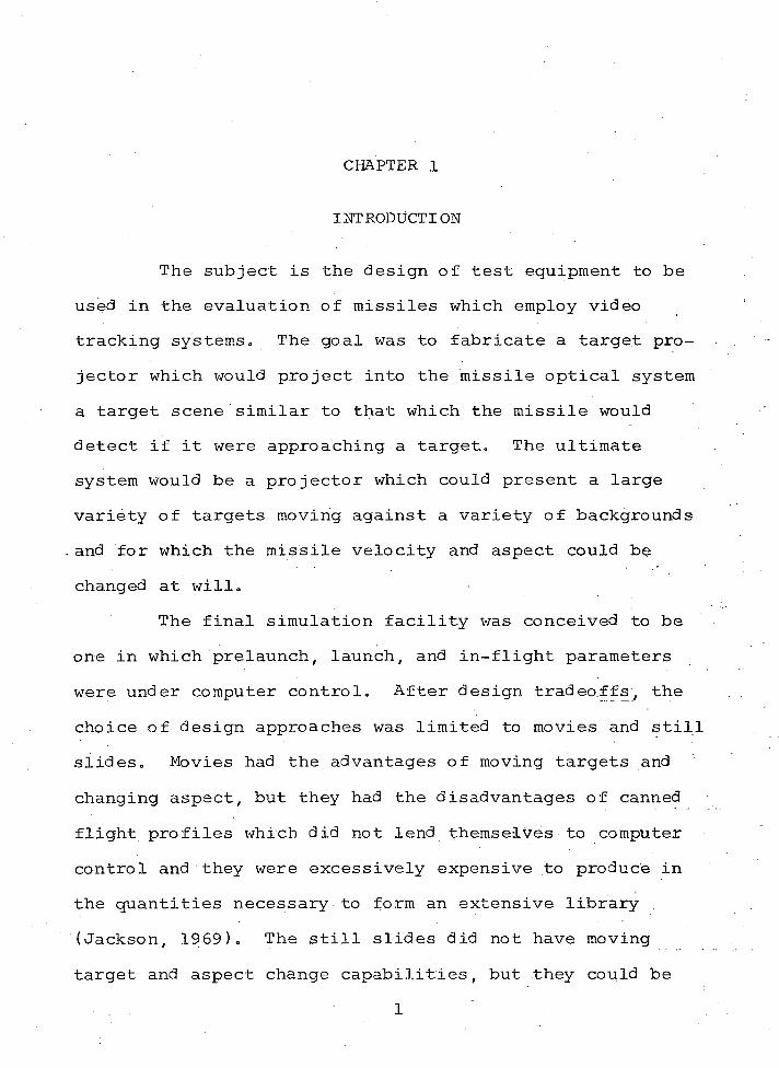
The subject is the design of test equipment to be used in the evaluation of missiles which employ video tracking systems. The goal was to fabricate a target projector which would project into the missile optical system a target scene similar to that which the missile would detect if it were approaching a target. The ultimate system would be a projector which could present a large variety of targets moving against a variety of backgrounds and for which the missile velocity and aspect could be changed at will.
The final simulation facility was conceived to be one in which prelaunch, launch, and in-flight parameters were under computer control. After design tradeoffs, the choice of design approaches was limited to movies and still slides. Movies had the advantages of moving targets and changing aspect, but they had the disadvantages of canned flight profiles which did not lend themselves to computer control and they were excessively expensive to produce in the quantities necessary to form an extensive library . (Jackson, 1969). The still slides did not have moving target and aspect change capabilities, but they could be • 1
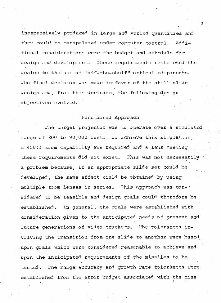
inexpensively produced in large and varied quantities and they could, be manipulated under computer control. Additional considerations were the budget and schedule for design and development. These requirements restricted the design to the use of "off-the-shelf" optical components.The final decision was made in favor of the still slide design and f from this decision, the following design objectives evolved.
Functional Approach The target projector was to operate over a simulated
range of 200 to 90,000 feet. To achieve this simulation, a 450:1 zoom capability was required and a lens meeting these requirements did not exist. This was not necessarily a problem because, if an appropriate slide set could be developed, the same effect could be obtained by using multiple zoom lenses in series. This approach was considered to be feasible and design goals could therefore be established. In general, the goals were established with consideration given to the anticipated needs .of present and future generations of video trackers. The tolerances involving the transition from one slide to another were based upon goals which were considered reasonable to achieve and upon the anticipated requirements of the missiles to be tested. The range accuracy and growth rate tolerances were established from the error budget associated with the miss
distance predictions. The following list of requirements represents the essential parameters of the design specification.. ("Design Specification SIMFAX MAVERICK Target Projector Subsystem," 1969) which were under the control of the author.
Zoom Requirements The zoom requirements imposed upon the lens and
servo system were as follows:1. The simulated range should be from 200 to 90,000
feet.2. The accuracy of the commanded range should be _+
2 per cent.3. The simulated missile velocities should be from
400. to 1,800 fps.4. The target growth rate should not exceed 4- 1 per
cent of the recommended rate.
Optical Requirements The following optical requirements were imposed upon
the simulator to ensure that the projected target scene was compatible with the missile optical system.
1. The projected target scene should be a square with a minimum angular subtense of 7.5 degrees.
2. With a high contrast 3 bar resolution pattern usedas a target, the optical system should have a minimum "on-axis" resolution of 20 TV lines/mi H i radian.
3. The exit pupil of the optical system is the position at which the missile entrance pupil is placed in order that the target scene may be viewed without vignetting. The position of the. exit pupil should be such that, when the missile is properly positioned, there will be no interference between the target projector and the missile or its supporting hardware.
4. The exit pupil should have a minimum diameter of 44.5mm.
5. Without a target slide, the average luminance of the projected scene should be greater than 750 foot lamberts.
,6. The luminance at 4; 3.5 degrees should be a minimum of 75 per cent of the "on-axis" luminance.
7. In an effort to increase the versatility of the’ ‘ r ‘target slide library, provision should be made to vary the contrast of the target slides.
Image Transfer Reguirements During a zoom sequence, the target projector switches
from one slide to another. To implement the initial slide alignment and to ensure an uninterrupted scene during the Slide transfer, the following provisions should be provided:
1. The target.slides should be of uniform quality and dimension.
2. To prevent an apparent lateral zoom of the target, provision should be made to center the expected aimpoxnt of the target on the optical centerline of the zoom system.
3. During the image transfer, the angular size of the target should not vary more than _+ 3 per cent.
4. During the image transfer, the rotational match, from slide to slide, should not exceed 0.2 milli- radian.
5. During the image transfer, the luminance of the projected scene should not vary more than + 10 per cent.
Scope of Thesis The target projector is a servo controlled zoom
system which can be operated both independently or under computer control. The completion of the project involved two major efforts; the optical design and the servo design/ computer interface. The author was the project engineer responsible for the design and fabrication of the optical system and Thomas Cargen and Dean Tebo were responsible for the servo and computer interface. The author was also involved in establishing the operational functions of the servo system and ensuring a proper interface between the optical and servo systems. During the following discussion, only the optical system will be discussed. Reference will be made to the operational functions of the servo system but

little attempt will be made to explain how these functions were accomplished„ Mention of the computer mode of operation is of little value in explaining the optical system except to illustrate how some design parameters were achieved„ Therefore, the discussion will be limited primarily to the independent or local mode of operation.
CHAPTER 2
PHYSICAL DESCRIPTION
This chapter is devoted to the physical description of the target projector and its operation. Figure 1 illustrates a plan view of the projector under discussion.
The projector is stationary and mounted on a table top approximately 28 inches from the gimbal axis of the missile tracking system. The exit pupil of the projector is positioned to be coincident and concentric with the entrance pupil of the missile.
Functional Description The following discussion explains the major optical
features and functions of the projector. Reference will be made to the appropriate items illustrated in Figure 1.
Zoom LensesThe 450:1 zoom is accomplished in three stages by
two 10:1 zoom lenses. The first lens, item 7, zooms through the initial part of the simulated flight and then the system switches to the second lens, item 9. While the second lens zooms, the first lens resets and the scene changes, by way of a movable mirror, item 5. The system then switches back to the first lens to complete the flight. The projected images

Figure 1„ Plan View of Target Projector1. TV Monitor Camera2. Control Console3. No. 3 Slide Holder and Source4. No. 1 Slide Holder and Source5. Swing-Away Mirror6. No. 1 and 3 Close-Up Lens7. No. 1 and 3 Zoom Lens8. No. 2 Close-Up Lens9. No. 2 Zoom Lens
10. Pellicle Beam Splitter11. No. 2 Slide Holder and Source12. Missile Reticle Selector13. Missile Reticle Holder14. Monitor Reticle Selector15. Monitor Reticle Holder16. Missile Collimating Lens17. Monitor Collimating Lens18. Removable Mirror19. Projector Exit Pupil20. Contrast Source21. Projector Exit Pupil/Missile Entrance Pupil22. Beam Splitter Cube
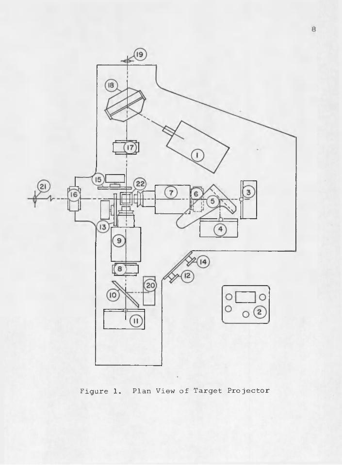
Figure 1. Plan View of Target Projector
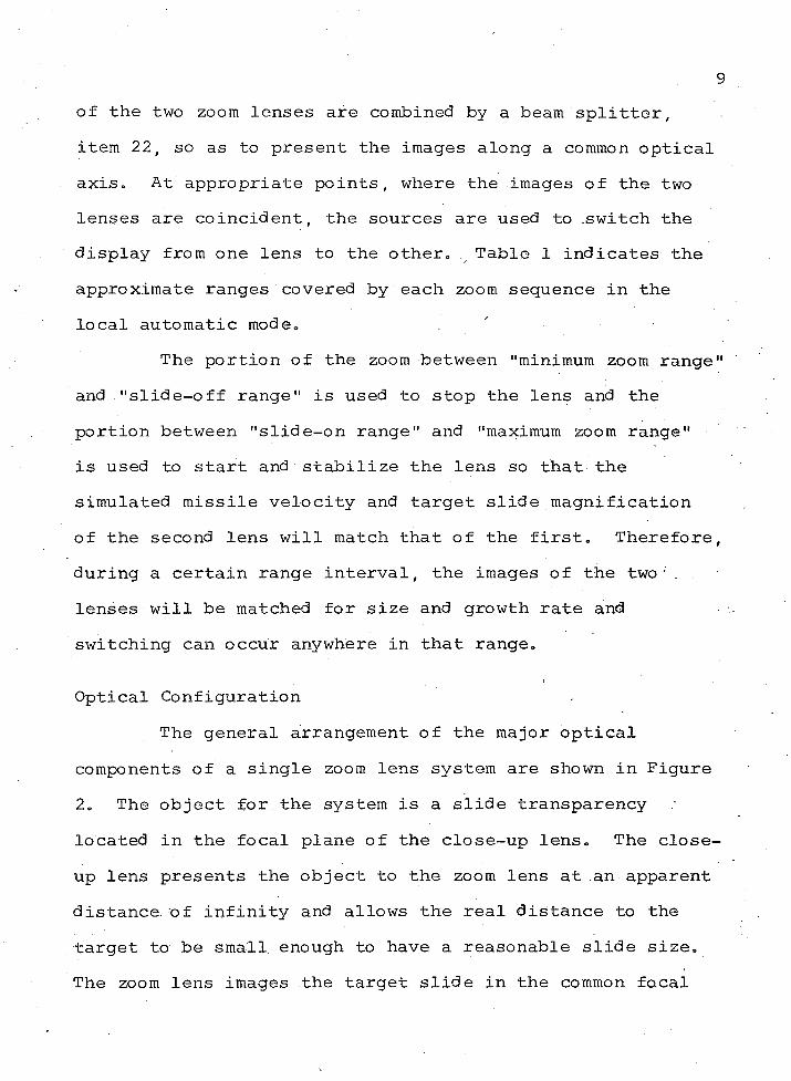
of the two zoom lenses are combined by a beam splitter, item 22, so as to present the images along a common optical axis. At appropriate points, where the images of the two lenses are coincident, the sources are used to .switch the display from one lens to the other. Table 1 indicates the approximate ranges covered by each zoom sequence in the local automatic mode.
The portion of the zoom between "minimum zoom range" and "slide-off range" is used to stop the lens and the portion between "slide-on range" and "maximum zoom range" is used to start and stabilize the lens so that the simulated missile velocity and target slide magnification of the second lens will match that of the first. Therefore, during a certain range interval, the images of the two'. . lenses will be matched for size and growth rate and switching can occur anywhere in that range.
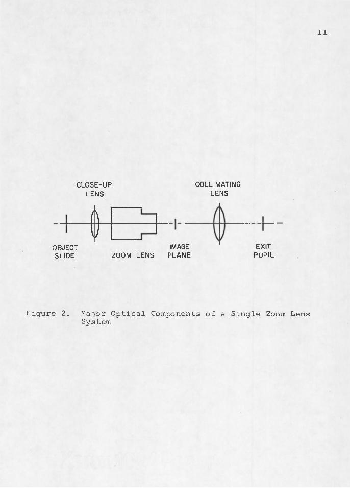
Optical ConfigurationThe general arrangement of the major optical
components of a single zoom lens system are shown in Figure2. The object for the system is a slide transparency located in the focal plane of the close-up lens. The close- up lens presents the object to the zoom lens at an apparent distance, of infinity and allows the real distance to the target to be small enough to have a reasonable slide size. The zoom lens images the target slide in the common focal
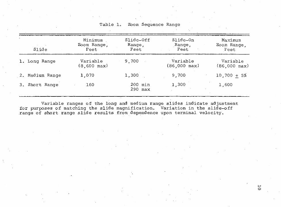
Table I, Zoom Sequence Range
SlideMinimum .
Zoom Range, Feet
Slide-Off Range, Feet
Slide-On Range, Feet
Maximum Zoom Range,
Feet
1, Long Range Variable (8,600 max)
9,700 Variable (86,000 max)
Variable (86,000 max)
2, Med ium Range 1,070 1,300 9,700 10,700 + 5%3, Short Range 160 200 min
290 max1,300 1,600
Variable ranges of the long and medium range slides indicate adjustment for purposes of matching the slide magnification. Variation in the slide-off range of short range slide results from dependence upon terminal velocity.
11
CLOSE-UPLENS
COLLIMATINGLENSe
OBJECTSLIDE ZOOM LENS
IMAGEPLANE
EXITPUPIL
Figure 2. Major Optical Components of a Single Zoom Lens System
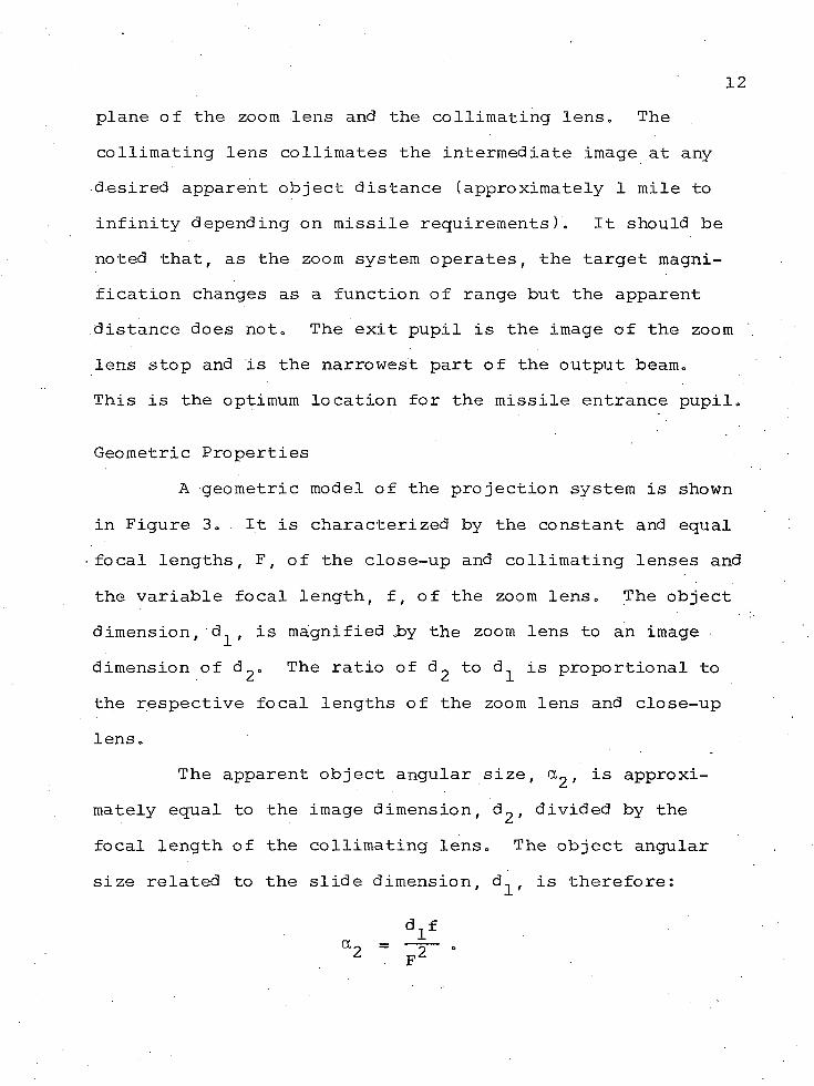
plane of the zoom lens and the collimating lens. The collimating lens collimates the intermediate image at any desired apparent object distance (approximately 1 mile to infinity depending on missile requirements). It should be noted that, as the zoom system operates, the target magnification changes as a function of range but the apparent distance does not. The exit pupil is the image of the zoom lens stop and is the narrowest part of the output beam.This is the optimum location for the missile entrance pupil.
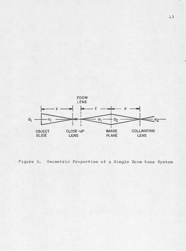
Geometric PropertiesA geometric model of the projection system is shown
in Figure 3. It is characterized by the constant and equal focal lengths, F , of the close-up and collimating lenses and the variable focal length, f , of the zoom lens. The object dimension,'d ^ , is magnified .by the zoom lens to an image • dimension of d 2 » The ratio of d 2 to d^ is proportional to the respective focal lengths of the zoom lens and close-up lens.
The apparent object angular size, , is approximately equal to the image dimension, d ^ , divided by the focal length of the collimating lens. The object angular size related to the slide dimension, d^, is therefore:
13
ZOOMLENS
COLLIMATINGIMAGECLOSE-UPOBJECTSLIDE LENS PLANE LENS
Figure 3. Geometric Properties of a Single Zoom Lens System
Additional FeaturesThe following items from Figure 1 are required for
complete operation of the target projector.
Light Source. The light sources (items 3, 4, 11, and 20) are a gas discharge type. Three are used to illuminate the target slides and the fourth is used to flood the target scene with light and thereby reduce the apparent contrast of the projected scene. Besides being relatively large, uniform sources, they can be switched on and off in 1/120 of a second or less without warmup or decay periods. The intensity can also be adjusted by special techniques.
Slide Holder. The slide holders are of two kinds. Both mechanisms have micrometer adjustments which move the target slides in the focal plane of the close—up lenses. Item 3 has X-Y adjustment to position the aimpoint of the target on the close range slide to be coincident with the optical zoom axis. Items 4 and 11 have X-Y and roll adjustments to align the remaining slides at the switch points.
Monitor. As a result of using a beam splitter cube, item 22, there are two identical images. The second image is used for matching the slides and certain calibration procedures. A second collimating lens, item 17, is used. The output beam is folded with a removable mirror,
15item 18, to get a more convenient arrangement of the hardware and to correct the reversed nature of the second image. The output is fed into a television camera, item 1, which is used to observe the target slides during the slide setup procedure.
Reticle. In the common image plane of the zoomlenses is a manually operated device (items 12, 13, 14, and .\ , •15) which allows a reticle to be inserted and superimposed on the target scene. The reticle has a crosshair which locates the optical zoom axis. This facilitates setting - the close range target slide at the desired point.
Control Console. The control console, item 2, contains the television monitor and the additional controls for operating the projector.
Operational Description The explanation of the target projector is further
clarified by explaining the manner in which it is used.This discussion lists the operational features of the projector. .
Control Console FunctionsThe following discussion lists the various functions
available at the control console.
16Range Meters, Range meters are provided to indicate
the simulated range of the target projector.
Mode Switch. The mode switch has three positions:(1) external, (2) local, and (3) computer. This switch selects where the source of the servo command originates.The external mode is used when special experiments are designed which do not require the local or computer mode.
In the local mode, the commands are generated .. internally. The control can be automatic or manual depending whether the Run/Reset switch is in Run or Reset.
In the computer mode, the computer controls the servo commands and source switching.
Local Control Pots. These pots are used to set up the local automatic mode of operation. An apparent constant ■. missile velocity of 0 to 2,000 fps can be set into the controls. A range pot is used in the local manual mode to adjust the target projector to any desired range from 0 to 86,000 feet. During local automatic mode, the zoom system will, reset to the range indicated by this pot. The start ranges of the long and medium slides are adjustable to facilitate matching the magnification of the slides at the switch points.
Run/Reset Switch. In the reset position, the zoom system resets to the range indicated on the range pot. When
17all the parameters for an automatic run have been set up, the automatic mode can be initiated by switching to the run position.
Light Controls. The power to the sources can be individually controlled and the sources can be independently switched on and off to facilitate matching the target slides.
Setup for Automatic ModeA typical setup procedure for a local automatic run
is as follows: The target slides are placed in theirappropriate holders, the range is manually adjusted to the terminal position of 200 ft and the reticle cross hair is manually moved into position. The close range slide is manually adjusted to position the desired target aim-point on the reticle crosshairs. The adjustment can be observed by watching the television monitor on the control console. The light source for the close range slide is then adjusted to the appropriate level.
The range is then manually adjusted to the first switch point of 1,300 feet and the reticle cross hair is removed. The light source, magnification, and orientation of the medium range slide are now adjusted to match that of the first. For rough alignment, the images of the two slides can be superimposed by turning on both the close and medium range sources. The magnification is matched by
18adjusting the maximum range of the medium range slide, X-Y and roll adjustment are made with the provisions on the slide holder. Images irradiances are compared by.alternately switching the two sources off and on. If no apparent motion of the target or scene irradiance change is perceived during this switching process, the matching is considered to be adequate.
The range is manually adjusted to the remaining switch point and the procedure is repeated by matching the far range slide and source to the medium range slide and source. The adjustment procedures are not as rigorous as might be imagined and all settings can be recorded so that they do not have to be rediscovered the next time around.
The range is now manually adjusted to the desired, start range of the zoom sequence and the appropriate constant missile velocity is dialed in. The automatic zoom sequence is then initiated by putting the run/reset switch in the run position. The zoom sequence can be repeated by switching to reset and then to run. Target contrast variations can be achieved by using the contrast source.By using this procedure, start ranges, apparent missile velocity, and average scene illumination are easily varied from run to run.
CHAPTER 3
OPTICAL DESIGN
The optical design of the target simulator can be divided into four sections. The first is the selection of major optical components and the determination of their effect on the system performance. This is followed by the source selection, the target slide adjustment techniques, and the target slide production. Most of the optical tests in the following discussion were accomplished with the assistance of Ellis Romer.
Major Optical Components • . .The design approach discussed in Chapter 2 was
finalized after an extensive tradeoff study. The major task was then one of selecting the appropriate zoom, close-up, and collimating lenses which would meet the design goals. Schedule and funding dictated the requirement that these items be "off-the-shelf" components.
Zoom Lens •The zoom lens was the most difficult item to procure.
When one considers that the terminal zoom sequence of a 10:1 zoom lens would be required to cover a range of 200 to 2000 feet at an apparent velocity of 1800 fps, it became
20apparent that the required lens must zoom, end-to-end, in less than one second. If this feature was not available in the original configuration, the lens must be capable of being easily reworked to this performance. The final configuration must also be rugged so that the performance would not degrade with extensive use.
All known zoom lens manufacturers in Europe, Japan, and the United States were contacted. The Varitol V lens with servo drive unit, manufactured by Rank Taylor Hobson of England, was the only lens meeting the requirements without extensive redesign. The lens was a standard production item and repair facilities were available at National Television Systems, Inc,, in Los Angeles. This was of primary importance because periodic maintenance could be performed with minimum down time and maximum convenience.
The descriptive literature of the lens listed the following specifications:
1. Range of focal lengths - 40 to 400mm.2. Maximum f/no - f/4.3. Image format - 32 x 24mm.4. Minimum zoom time - approximately 3/4 sec.5. Maximum zoom time - approximately 5 minutes.
In addition, the lens was available with XI. 5 and X2 focal length range extenders. These extenders increased the focal length range and f/no and decreased the zoom lens angular field of view by a multiple of the extender value.
21The lens was available for lease from National
Television and the lens, with extenders, was obtained for final evaluation..
Close-Up LensA close-up lens was required for two reasons: (1)
the real object distance must be short enough to allow for the use of an 8x10 inch slide; this was the largest slide which could be utilized with available equipment; (2) thezoom lens could only zoom and stay in focus when the object distance was between six feet and infinity and the minimum six foot distance would still necessitate an excessively large slide and source.
The usable diameter of the zoom lens was 125mm. The close-up lens must therefore have an equivalent diameter or greater and as short a focal length as practical. When all available sources were examined, the lens which met the necessary requirements was a war surplus lens which could be procured from Jaegers. The f/2.2 lens had a focal length of 273mm. Since the lens was readily available, one was purchased for evaluation.
Lens ExaminationHaving obtained the lenses, they were assembled in
their intended manner on a Gaertner optical bench together with an available 50mm beam splitter cube (see Figure 1).The characteristics to be examined were the image quality,
22the useful image size, the relationship between the focal length and the servo drive position indicator pot, and the servo drive characteristics.
The optical quality was evaluated by placing an Air Force 3 bar resolution target in the focal plane of the close-up lens and examining the zoom lens image with a Gaertner microscope. In all cases, the on-axis resolution exceeded 50 line pairs per millimeter (Ip/mm) at the long focal length and 120 Ip/mm at the short focal length. Intermediate focal lengths produced intermediate resolution values. At a distance of 30mm from the optical axis, the resolution was 40 Ip/mm for the long focal length case, while for the short focal length, it was less than 10 Ip/mm. The latter value was evaluated to determine whether it was compatible with the objectives of the target projector.
The missile attempts to detect the difference between the target and the immediate background and the remainder of the target scene is used to set the missile AGC. Also, the target area of interest would always be located on-axis and, except for the terminal range, the target would be only a small fraction of the total field. At the terminal range, the zoom lens would be at the long focal length and, under this condition, the resolution was satisfactory.As a result, the short focal length "off-axis" resolution was considered to be of minor importance and therefore adequate for the intended purpose.
23The useful size of the zoom lens image was deter
mined by placing a fluorescent light table in the focal plane of the close-up lens. The tube of the light table provided a wide uniform source which could be observed and measured in the zoom lens image plane. This line image was scanned with an EG&G Model SGD100 silicon detector. The useful diameter of the image measured to be approximately 57mm. Beyond this limit, the lens vignetted excessively. Since a square field was required, the maximum useful field for the target projector could therefore be assumed to be the inscribed square with a side dimension of 40mm. This 40mm field was further examined with each of the extenders to determine the uniformity of the field. The criterion for evaluation was the ratio of the irradiance at the edges of the 40mm field as compared to the center of the field. With no extender, this ratio was 55 per cent. With the XI.5 and X2 extenders, the values were 82 and 95 per cent, respectively (see Table 2).
The focal length and servo drive relationship was determined by measuring the zoom lens focal length with the Gaertner Nodal slide attachment and comparing the resultant value with the corresponding servo drive position indicator pot. The manufacturer had stated that the relationship was one in which the control position was proportional to the logarithm of the focal length. The results of many measurements on the leased lens and the final
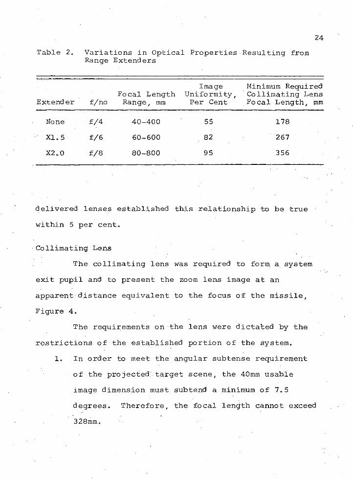
24Table 2. Variations in Optical
Range ExtendersProperties Resulting from
Extender f/noFocal Length Range, mm
Image Uniformity, Per Cent
Minimum Required Collimating Lens Focal Length, mm
None f/4 40-400 55 178XI. 5 f/6 60-600 82 267X2.0 f/8 80-800 95 356
delivered lenses established this relationship to be true within 5 per cent,
•Collimating LensThe collimating lens was required to form a system
exit pupil and to present the zoom lens image at an apparent distance equivalent to the focus of the missile, Figure 4.
The requirements on the lens were dictated by the restrictions of the established portion of the system,
1, In order to meet the angular subtense requirement of the projected target scene, the 40mm Usable image dimension must subtend a minimum of 7,5 degrees. Therefore, the focal length cannot exceed 328mm.
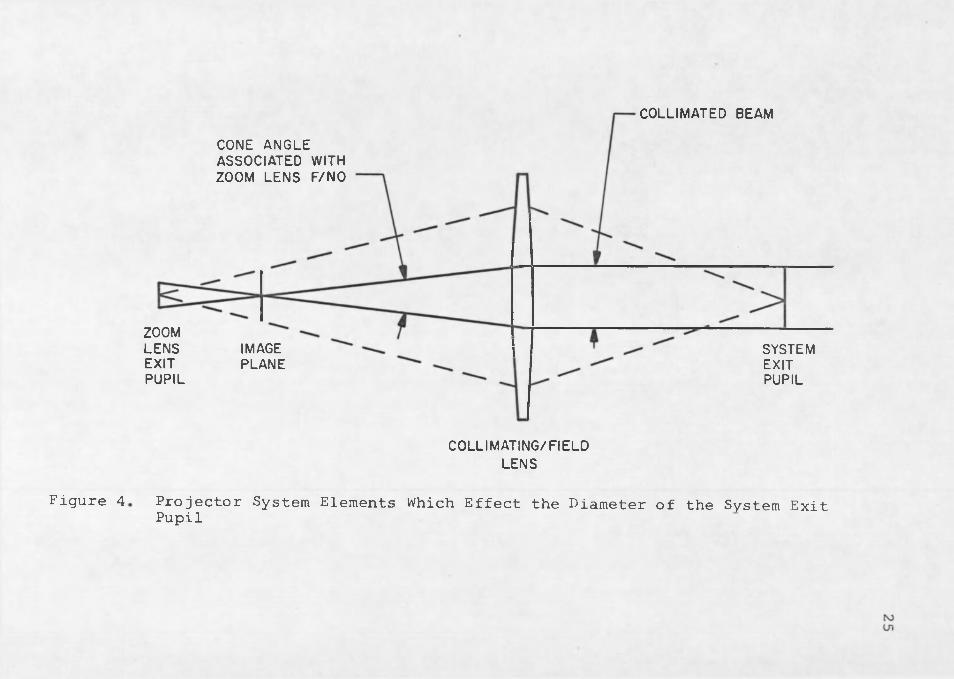
Figure 4
COLLIMATED BEAM
CONE ANGLE ASSOCIATED WITH ZOOM LENS F/NO
ZOOMLENSEXITPUPIL
IMAGEPLANE
SYSTEMEXITPUPIL
COLLIMATING/FIELDLENS
Projector System Elements Which Effect the Diameter of the System Exit Pupil
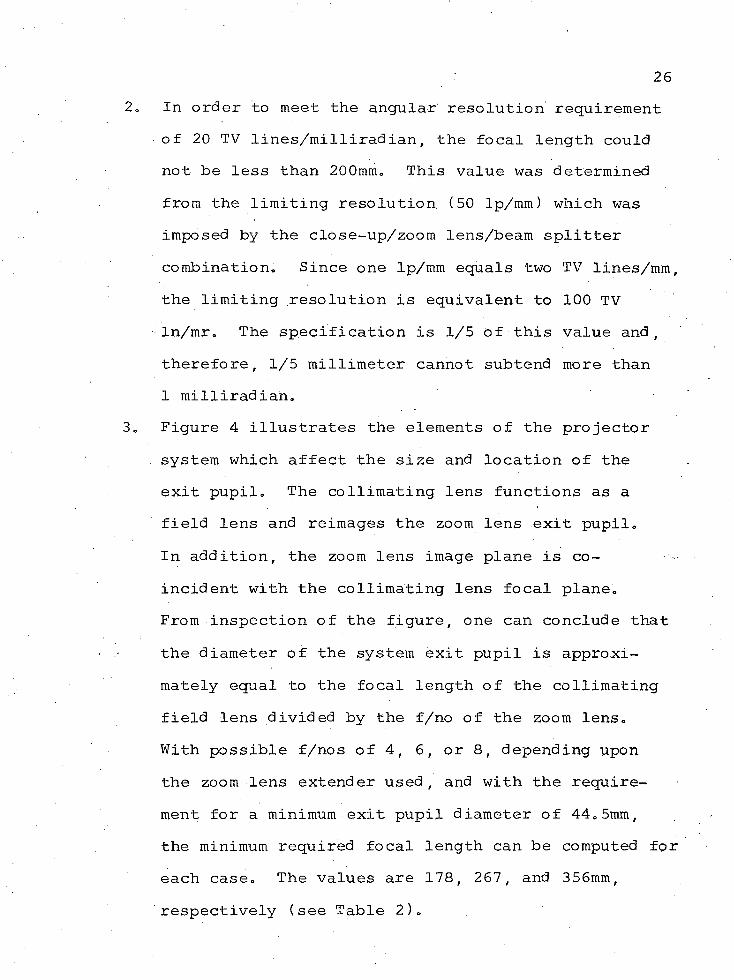
In order to meet the angular" resolution requirement of 20 TV lines/milliradian, the focal length could not be less than 200mm. This value was determined from the limiting resolution (50 Ip/mm) which was imposed by the close-up/zoom lens/beam splitter combination. Since one Ip/mm equals two TV lines/mm, the limiting resolution is equivalent to 100 TV In/mr. The specification is 1/5 of this value and, therefore, 1/5 millimeter cannot subtend more than 1 milliradian.Figure 4 illustrates the elements of the projector system which affect the size and location of the exit pupil. The collimating lens functions as a field lens and reimages the zoom lens exit pupil.In addition, the zoom lens image plane is coincident with the collimating lens focal plane.From inspection of the figure, one can conclude that the diameter of the system exit pupil is approximately equal to the focal length of the collimating field lens divided by the f/no of the zoom lens.With possible f/nos of 4, 6, or 8, depending upon the zoom lens extender used, and with the requirement for a minimum exit pupil diameter of 44.5mm, the minimum required focal length can be computed for each case. The values are 178, 267, and 356mm, respectively (see Table 2).
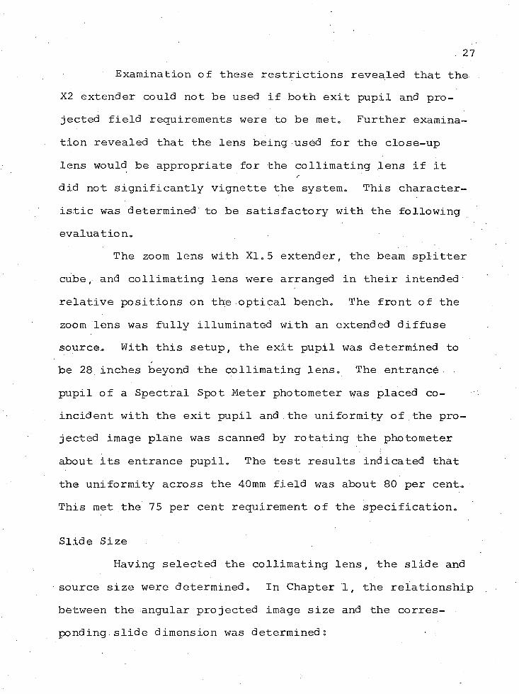
27Examination of these restrictions revealed that the
X2 extender could not be used if both exit pupil and projected field requirements were to be met. Further examination revealed that the lens being used for the close-up lens would be appropriate for the collimating lens if it did not significantly vignette the system. This characteristic was determined to be satisfactory with the following evaluation.
The zoom lens with XI.5 extender, the beam splitter cube, and collimating lens were arranged in their intended relative positions on the optical bench. The front of the zoom lens was fully illuminated with an extended diffuse source. With this setup, the exit pupil was determined to be 28 inches beyond the collimating lens. The entrance. pupil of a Spectral Spot Meter photometer was placed coincident with the exit pupil and the uniformity of the projected image plane was scanned by rotating the photometer about its entrance pupil. The test results indicated that the uniformity across the 40mm field was about 80 per cent. This met the 75 per cent requirement of the specification.
Slide SizeHaving selected the collimating lens, the slide and
source size were determined. In Chapter 1, the relationship between the angular projected image size and the corresponding, slide dimension was determined: • .
28
f2
In this relationship, a is the angular projected size of d in radians, d is the corresponding slide dimension, f is the zoom lens focal length, and F is the common focal length of the close-up and collimating lenses. The maximum slide size is required when the zoom lens has the minimum focal length of 60mm. Since F has a value of 273mm, the maximum required slide size for a = 7.5 degrees was computed to have a value of 175mm or 6.9 inches. This is within the original restriction of 8x10 inches and, therefore, considered to be satisfactory.
System Analysis ' . .With the basic optical system now being firm, the
only factors left to be determined were whether or not the velocity and range requirements could be met. The zoom lens and servo drive unit were delivered to Thomas Cargen and Dean Tebo, of the Electronics Department, to determine the dynamic properties of the system. The results of their investigation produced the following results:
1. The maximum excursion of the cell containing the zoom elements was 4.65 inches.
2. The maximum velocity of the zoom cell was 14 inches/ second.
293. The maximum time to start and stabilize the servo
drive system was 150 milliseconds„4. The time required to stop the lens cell when it was
under maximum velocity cohditions was 100 milli-. secondso
The dynamic characteristics of the zoom system can be . •
determined from these parameters.The zoom lens has an approximately linear relation
ship between the mechanical position of its control mechanism and the logarithm of its focal length. The position pot is a direct measpre of the control mechanism position or zoom lens cell position. This linear relationship is stated in normalized form in (2), where Y is the mechanical position of the zoom cell.
Y = Ymax lo9lO (2)
Note that in this equation the full range of thezoom cell, 0 to Ymaxf is covered when the focal lengthchanges by a factor of ten (f = 10 f . ). Inspection of3 -1 max mxnEquation (1) establishes the fact that the projected angularfield is proportional to the zoom lens focal length, andthe following relationship is therefore obtained:
a “ f. a . “ f .2 2 m m m m
30In this relationship, subscripts 1 and 2 represent any corresponding values of ct and f„
Equation (2) may be written in terms of cc by substituting Equation (3) into Equation (2)„
Y = Ymax log10 (oc . ) (4)min
In the application under consideration, the productof the angular target size, . 0-, and the range to the target,R, is required to be constant,
OCR = a Rm m max
Thus, the position of the zoom lens cell, Y , can be related to the range by substituting the preceding relationship into Equation (4).
RY = Y m B x ^ 1 0 ( ^ ) (5)
The velocity of the zoom lens cell is the time derivative of (5).
Y = Ymax (Tr> lo9l0 <e) <6)
Since Y was equal to 4.65 inches and (Y) was max ^ maxequal to 14 inches/second, it seemed probable that the maximum missile velocity, R, of 1800 fps could be simulated down to a minimum range of 260 feet. In actuality, it couldnot because there was insufficient distance to stop the
31lens. For this reason, the minimum range for the 1800 fps condition had to be modified to 290 feet.
Because of the dependence between stopping distance and simulated velocity, the servo drive system was provided with a rate sensor to determine the zoom lens cell velocity, Y, and thereby modify the required stopping distance. With this feature, the terminal range could be reduced as the missile velocity was reduced and the 200 foot minimum range could be achieved when the missile velocity was 400 fps.This, is the explanation for the variable "slide-off11 range listed in Table 1.
Through an iterative process between Equations (5) and (6), the various slide switch points listed in Table 1 were determined. The maximum range of the medium-range slide was given a + 5 per cent adjustment to facilitate matching the magnification of the close- and medium-range slides at their switch point. The long-range slide was made adjustable for the same reason. But in this case, ,the adjustment was made such that the long-range slide could overlap the medium-range slide. This additional adjustment was required to improve the resolution of slides containing certain targets.
Source Requirements The requirements of the system indicated that the
sources should have the following features:
lo They must be large enough to fully illuminate thetarget slides and be sufficiently uniform so as not to degrade the uniformity requirements of the projected field„
2. They must be intense enough to provide an operable level of radiant flux to the missile when a target slide with a 20 per cent average transmission is used (see discussion in Appendix A )„
3. They must be adjustable so that the slide illumination can be matched and adjusted to various levels.
4. They must turn off and on in such a fashion that anychange in the level of illumination at the moment ofswitching would not adversely affect missile function.
Source SelectionFour sources were required, three for the slides and
one for the contrast source. The contrast source was to be used with a pellicle beam splitter and the mid-range zoom lens to provide the capability of varying the apparent target contrast (see Figure 1). The most logical choice for a large, uniform source was a coiled gas discharge tube whose uniformity was enhanced by the use of a diffuse screen in front of the tube.
One of the first questions to be raised was whether the 120 cps flicker would affect missile performance. Since
33the working surface of vidicon faceplate was of an integrating nature with an appreciable time constant, the flicker of the sources was determined to be unimportant.
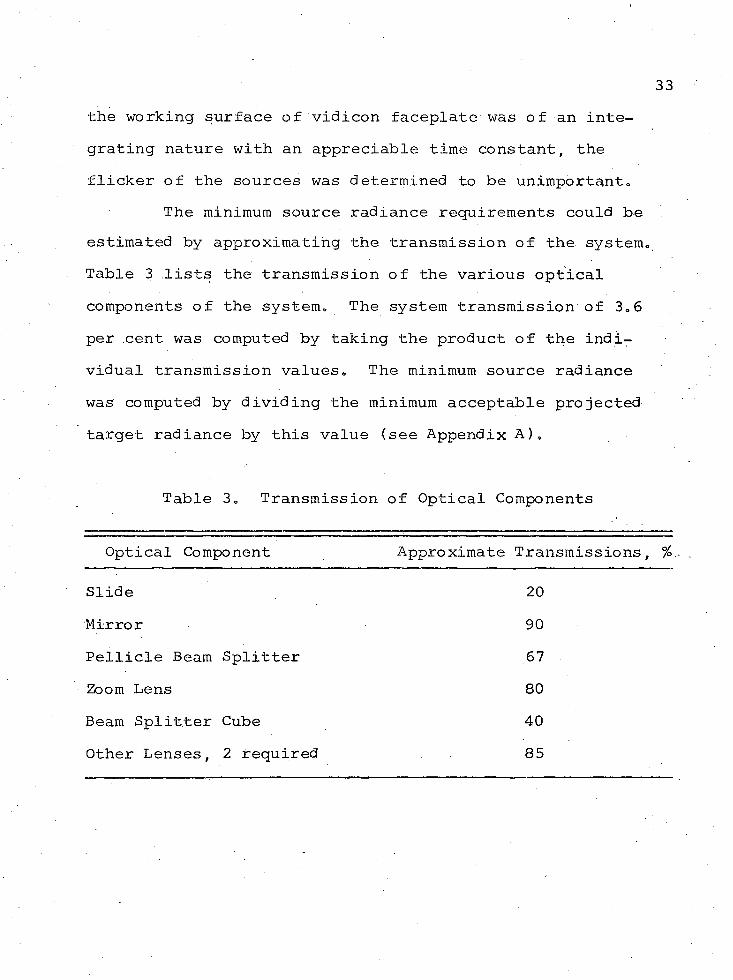
The minimum source radiance requirements could be estimated by approximating the transmission of the system. Table 3 lists the transmission of the various optical components of the system. The system transmission of 3,6 per cent was computed by taking the product of the individual transmission values. The minimum source radiance was computed by dividing the minimum acceptable projected target radiance by this value (see Appendix A),
Table 3, Transmission of Optical Components
Optical Component Approximate Transmissions, %
Slide 20Mirror 90Pellicle Beam Splitter 67Zoom Lens 80Beam Splitter Cube 40Other Lenses, 2 required 85
34Sources meeting these specifications were available
from Aristo Grid Lamp Products, Inc. In addition, a variety of colors was available. The tube color was dependent upon the gas which filled the tube and the phosphers which were used to line the tube. The final choice of color was red.
This decision was based upon the following reasoning. The typical vidicon spectral response is similar to the photopic curve, except for extended long and short wave length performance. For the purpose of improving the target contrast by discriminating against atmospheric haze, the missile would typically have a red filter, such as a Wratten 25. The filter would therefore limit the short
Iwavelength end of the spectral passband to approximately 600 nm while the vidicon would limit the long wavelength end to approximately 740 nm. The red source naturally fell within this region of interest. An additional benefit derived from the red source was an improved optical performance due to the reduction of the chromatic aberrations.
The sources were procured and determined to be capable of radiance levels of two and one-half times the minimum requirement and to be uniform within their advertised value of 10 per cent.
Source ControlsThe controls took advantage of the cyclic nature of
the gas discharge source (Vanderveire, 1969). The source
35would not function until a minimum excitation voltage had been obtained and it would extinguish when the voltage dropped below this same value. Therefore, as the AC supply voltage increased, the source would turn on and then extinguish again as the supply voltage decreased (see Figure 5). The sequence was repeated on the negative half of AC cycle. As a result, the source would turn on twice during the AC cycle and, therefore, had a flicker frequency of 120 cps or a period of 8-1/3 milliseconds. The source on-time could be varied by adjusting the peak amplitude of the AC supply from just above the source threshold voltage to a maximum rated source voltage. The resulting on-time could therefore be varied from 2 to 6.33 ms and this adjustment constituted the means of varying the source luminance over a 10 to 1 range.
The slide sources were powered by separate legs of a three-phase power supply and the phase difference between sources could therefore be determined. The switching logic was designed so that two sources were never on together.In the process of switching, there are two time delays involved, switch off delay and switch on delay. At the time of command for switching, if the source to be turned off is in its ON condition, the command to switch the other source on will be delayed until the first source reaches its OFF condition. If the source to be turned off is already in its OFF condition, there is no switch off delay time.
LIG
HT
INTE
NSI
TY
AC
SUPP
LY
VO
LT
AG
E MAX MINIMUMEXCITATIONVOLTAGE
MIN
ON
O FFTIM E OFF p - TIME ON
[ * - 8 > 3 MS
T IM E
Figure 5. Source Intensity Waveform
U)cn
Following the time that the first light does go off, there is a 2 ms relay delay time involved in connecting the second light source to its source of power. The second source will come on at the end of a 2 ms delay if the magnitude of its supply voltage is above the firing threshold. An additional delay will occur if the phase relationship is such that the second source's supply voltage is below the firing threshold.The result of this logic was a time delay between sources of
^ . .2 to 8 ms, or up to one pulse of the source frequency could be missing. This was not considered to have an adverse effect on the missile performance,
-Miscellaneous FeaturesThe remainder of the target projector design fallowed
naturally from the established portion of the design. The mechanical features were completed with the assistance of Art Thompson and William Biggs,
Television Camera— Monitor. As a result of using a beam splitter cube, there were two identical images. The second image was used for aligning the slides and certain calibration procedures. A second collimating lens was naturally required. The second output beam was folded with a removable mirror to yield a more convenient arrangement of the hardware and to correct the reversed nature of the second image. The second image was used by a television
38camera-monitor system to observe the slides during the slide setup procedures.
The folding mirror was made removable to make the second image available for periodic calibration procedures. The differences between the primary missile image and the secondary monitor image were considered to be insignificant and therefore suitable for calibration purposes. Had this second image not been available, the routine calibration would have been seriously handicapped by the permanently mounted missile supporting hardware. This hardware was positioned opposite the primary missile image position and was therefore in the way.
Alignment Reticle. An alignment reticle was required to center the intended target aimpoint on the optical zoom axis. If this centering feature were not . accomplished, the target could laterally zoom out of the field of view of the missile. Two manually operated reticles were provided, one for the missile image and one for the monitor image. Both reticles could be removed and replaced by a clear glass slide. The clear glass slide insured that the apparent focus of the target would not change.from one condition to the other.
Target Holders. Special target slide holders were required in order that the target slides could be properly aligned to be coincident with each other. Target slide
39production allowed for centering within 1/16 inch but provision was required for final alignment of X-Y position and roll. These features were accomplished with slide holders which incorporated adjustment screws. The screws-were, in fact, micrometers which provided values for recording of adjustments. With this feature, the settings would not have to be rediscovered after they were established the •first time.
Target Slide ProductionThe production of the target slides involved the
Goodyear blimp, helicopters which were modified with stable platforms for the movie industry, trucks which incorporated extension booms for the fruit picking industry, and the U. S. Army with its range and target facilities. The range and target facilities were under the direction of Jim Keihner, the photography and target negative production were under the direction of Jim Dell, and coordination of the two was under the guidance of Jess Jackson and the author.
Initially it was desired to have the maximum background detail. The original plan was to utilize three cameras with lenses of appropriate focal lengths and to use the Goodyear blimp to achieve realistic target aspects.This approach was soon abandoned because the three negatives were not of uniform quality and the target slides produced from these negatives could not be properly registered. .In
40addition, appropriate magnification ratios could not always be achieved because there was an insufficient variety of cameras and lenses available for lease.
During the second phase, a single photographic negative concept was adopted. This concept eliminated the problems encountered in the first attempt, but involved a certain amount of development before it was established as the standard operating procedure. The fruit picker was used as a platform when economy was of primary importance and •limited target aspect was acceptable. A helicopter with a stabilized platform was used when maximum versatility was required„
One of the first objectives was to determine the photographic-negative resolution capability imposed by the helicopter, photographer ability, existing camera, performance, and film processing capabilities (Keihner, 1969). These limitations were determined in one test series in which high contrast three bar ground targets were photographed. The available helicopter, photographer, etc., were used. After processing under normal conditions, the photographs were examined. The results of the test indicated that under average conditions, 30 Ip/mm could be resolved. Since 30 Ip/mm was the limit of our capabilities, the remaining question was whether this limit was compatible with the requirements of the system.
41Resolution Requirements
Dr. Schneider prepared the following argument to convince the skeptics that 30 Ip/mm would produce adequate results.
Three slides would be made from a single 4x5 inch negative. The photographs would be taken such that, on the negative, the maximum target dimension would be 16 per cent of the 4x5 negative dimension. This was accomplished by using a 4x5 aspect reticle in the view finder of the taking camera. When the photograph was taken, the range was selected such that the maximum target dimension appropriately touched one of the reticle limits. The 16 per cent had been determined to be a satisfactory ratio of target to background dimensions for proper missile operation. The slides were to be processed by enlarging or reducing the negative as required. '
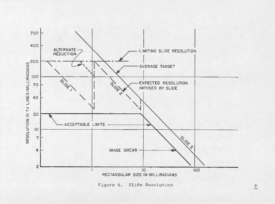
The first step was to establish an acceptable resolution criteria and then to compare the slides to it. Figure 6 is a plot of resolution in TV lines per milliradianversus target size in milliradians. Right away, the 20 TVline per milliradian of the specification can be drawn.Under static conditions, this value holds for any target size and is therefore a straight line.
Under certain conditions of range, velocity, andimage size, this value can be reduced because of the image smear On the vidicon. The image smear can be computed by
RESO
LUTI
ON
IN TV
LI
NE
S/M
ILLI
RA
DIA
NS
700
400ALTERNATEREDUCTION
LIMITING SLIDE RESOLUTION
200AVERAGE TARGET
100EXPECTED RESOLUTION IMPOSED BY SLIDE
70
40
20ACCEPTABLE LIMITS
IMAGE SMEAR
100RECTANGULAR SIZE IN MILLIRADIANS
Figure 6 . Slide Resolution ^
43the following equation:
Image smear = ( -) At
where Image smear = radians.W = Target size in feet.R = Range in feet.o 'R = Velocity in fps.
At = Vidicon Field time, 1/60 sec.W
2 ^ = 1/2 Target size in radians.
Assume a least case R/R of 2 (R = 400 fps and R =200 ft). For additional conservatism consider only 1/3 of the total smear. The equation then transforms to
Imag e^smear _ mr/TV llne '
where w equals the target size in milliradians, and each element of Irria9e^s.!)iear is considered the minimum resolvable element and therefore equal to one TV line. The equation can now be inverted so that it applies directly to Figure 6 .
TV line/mr = 180/w
When this line is added to the graph, we see that there is a considerable relaxation for larger image sizes. The bold line is now our required slide resolution. By this criterion, any slide with resolution falling above the line is acceptable. ,
• 44Now consider the slides, Assume that 5/6 of the
resolution of the photographic negative, 30 Ip/mm, can be transferred to the slide. There is therefore a usable resolution of 25 Ip/mm or 50 TV In/mm. Assume, at first, that the total quantity is reproduced„ The number of resolution elements on the slide would therefore be equal to the resolution of the photographic negative divided by the magnification used in making the slide. This value of M would probably run from about 2 to 0.1.
Now take the average case of a target which has a1 to 3 height to width ratio and which is 16 per cent ofthe negative width. The width is 5 inches, or 125 mm. The resolution is 50 TV lines/mm. The total number of resolution elements across the width of the film is therefore•6250 TV lines. Since the width of the target is 16 per cent of that, there are 1 0 0 0 resolution elements in the width of the target. The important target dimension is the minimum dimension which in this case is the height. Since the height is 1/3 the width, the height has 333 resolution elements.As the target is magnified, it will have different angular sizes with a fixed number of resolution elements in it. Wecan relate this to the graph in the following way:
m T 7 t /__ Resolution elements in targetTV in/mm = - Target size in mr
This example is plotted on Figure 6 as "average target."
45So far, the assumption has been made that 5/6 of
the photographic-negative information is transferred to the slide. This is no strictly true. The slide has a limiting resolution of approximately 80 Ip/mm or 160 TV line/mm.When this limit is combined with Equation (1 ) and the zoom lens short focal length, a limiting slide resolution of 200 TV lines/mr is established (see dash-dot line on Figure 6 ).. During a complete 3-zoom sequence, this limit would cause an abrupt variation in resolution as indicated by the dashed line on Figure 6 . Typically, the first slide would have the maximum resolution and, during the first zoom sequence, as the angular size of the target increased the number of TV lines per milliradian would decrease. At the switch point from slide 1 to slide 2 , there is an abrupt increase in the number of resolution elements per milli- radians. This change is again observed at the switch pointfrom slide 2 to slide 3. In many cases, the maximum reduction of slide 1 would not be required because the resultingprojected image would be too small to be of value. In. thesecases, the reduction of slide 1 could be revised and, thereby, improve the transition from slide 1 to slide 2 .This alternate reduction is depicted by the dotted line.This capability was considered desirable and this is the reason that the long range slide magnification adjustment, as indicated in Table 1, was made to completely overlap that of the medium range slide.
46By employing this technique, it was anticipated that
all primary and most secondary targets could be adequately displayed. In difficult cases, where the transitions were severe, it was expected that the missile would make the transition through the poorer resolution zone without difficulty.
In the preceding discussion, consideration was given to only the resolution properties of the slides. Two additional factors were significant in evaluating the adequacy of the slide presentation. First, during the use of the target projector, it was determined that a good gray scale in the target slides was of significantly more importance than the resolution. In addition, the target projector simulated the change in target size, but not the defocus resulting from a change in range. This defocus would have manifested itself as poor image quality at close ranges. In the simulation, the projected slide quality was degraded at the close ranges due to the large magnification of the original negative. It is the opinion of the author that these two phenomena would tend to compensate for each other and, therefore, the missile would detect a more realistic situation.
Slide ProductionConsidering the fact that everything was proceeding
in a well established direction, one remaining problem was
47plaguing the production of target, slides. When reductions of the target negative were used to produce slides, there was a large blank area surrounding the reproduced scene.This would adversely affect the performance of the missile AGC. To prevent this unrealistic situation, it was necessary to dub in the background, surrounding the reduced negative, in such a fashion that the dubbed-in background matched the average density of the negative.
The initial attempts to dub in the background involved a laborious process of selecting multiple thicknesses of various available materials in an attempt to achieve a satisfactory blend. Howard Morrow, a student at the University of Arizona Optical Science Center and summer employee at Hughes Aircraft Company, developed a more reasonable procedure. Two large sheets of polaroid material were employed. In the first sheet, a hole was made which matched the size of the negative. The negatives had . previously been punched to a standard size. The second sheet was mounted in such a fashion that it could be rotated. With this arrangement, the second sheet could be rotated until the dubbed-in background matched the average transmission of the target negative mounted in the first sheet. If additional dubbing was required on slides. involving very large reductions, this dubbing was achieved with emulsion dyes after the slide was completed.
The production of the final target slide sets involved the following procedures:
1. After measuring the dimension of the target on the negative, the user of the target projector computed the various slide magnifications which were required. This calculation was based upon the desired range to be simulated and the slide scale factor established in Equation (l).
2. The photographer in charge of slide production adjusted the Polaroid sheets to achieve a satisfactory blend from target scene to dubbed-in background . The angle of the second polaroid sheet was an indication of the proper exposure to be used.
3. The relative exposures of each slide were computed from the required magnifications and the three exposures were made on Kodalith Ortho Plate, Type 3.
4. The glass plates were simultaneously developed in a 2 to 1 mixture of water and DK-50 until the dubbed- in background achieved a density of .4 to .6 . This density was determined by comparing the developing slide to a standard step tablet. The development time of each individual slide in a set was not necessarily the same and the processing was stopped on an individual basis as previously described.
5. If the resulting slide sets would not perform satisfactorily in the target projector, they were

49reproduced in part, or in their entirety. The requirement for this remaking of slides was a rare occurrence.
CHAPTER 4
TARGET PROJECTOR PERFORMANCE
The remaining task was to check out the final performance of target projector. This was accomplished at the Hughes facility in Canoga Park. The following is a brief summary of the test setup and measured performance.
Zoom Requirements The manual and local automatic modes of operation
were not tested for performance accuracy. The projector was to be operated under computer control and the expected performance in this mode of operation was to be determined.
Static CalibrationThe final ability of the target projector to meet '
the 2 per cent range accuracy under static conditions was never in doubt. This was simply a matter of calibration, and the calibration became a part of the computer programming. The static calibration was accomplished using a Kern DKM-3 theodolite and a specially fabricated high contrast square target slide. The slide was placed in the appropriate target holder and the theodolite was placed at the target projector exit pupil. Various servo positions were commanded and resulting angular image size was measured
50
51with the theodolite. Since the product of the range and angular target size was to remain constant, the deviations from this condition could be determined to the satisfaction of the user.
Dynamic CalibrationThe author was not involved in this phase of the
project and after the target projector had been in servicefor a while, Robert Peterson (1969) performed the dynamic.calibration, Mr. Peterson concluded that the zoom servowould "provide adequate dynamic performance for a largepercentage, if not all, of the 'production test 1 trajec-
. \tories planned for SIMFAX,"
Optical Requirements It was impractical to perform the optical tests from
the missile exit pupil position because the flight table, which supports the missile, was in the way and prevented proper placement of the measuring equipment. By removing the folding mirror, the monitor exit pupil was located in a convenient position and the tests were performed from that location.
Projected Angular FieldThe angular subtense of the projected target scene
was to have a minimum value of 7,5 x 7,5 degrees. This measurement.Was made with a Kern DKM-3 theodolite. The
52reticle holder acted as the field stop and established themaximum, field limits at 8.7 x 8.7 degrees. Except for theshort focal length position of the zoom lens, the entire field was usable. At the short focal length, vignetting of the optical system reduced the field to a diameter of 9.31 degrees. Under this condition the required 7.5 degree square field had dark corners, but since the field quickly filled out as the lens zoomed, this deviation was considered acceptable. .
Exit PupilThe diameter of the exit pupil was determined in the
following manner. The location,of the pupil was found by turning on a target source, dimming the room lights, andplacing a white card in the appropriate position. Thediameter was then measured with a ruler and determined to be approximately 46 mm.
ResolutionThe on-axis resolution was determined by placing a
standard high contrast three bar resolution target in the target holder and observing the minimum resolvable target pattern with the DKM-3 theodolite. From the standard target spacing and the relationship established in Equation (1), the angular resolution in TV In/mr could be established. In each case, the long focal length end of the zoom had the poorest resolution and each of the three zoom sequences was
53measured in this position. The resulting values of 25.2, 31.7, and 36 TV In/mr exceeded the required value of 20 TV In/mr.
LuminanceThe minimum image luminance of 750 foot lamberts,
without a target slide, was measured with a Spectral Spot Meter photometer placed at the exit pupil of the system.Care was given that the exit pupil of the projector was coincident and concentric with the entrance pupil of the photometer. The exit pupil of the target projector overfilled the photometer lens system. Under any combination of zoom lens or angular field position up to 3.5 degrees., the luminance exceeded 1 0 0 0 foot lamberts when the sources were at maximum brightness.
UniformityThe requirement for a uniformity of 75 per cent or
greater at 3.5 degrees was measured with a same setup as described under luminance. The ratio was measured at maximum range, each switch point and minimum range with the following results. At the maximum range of 86,000 feet, the ratio was a minimum of 76 per cent. At the first switch point of 9700 feet, the minimum values were 87.5 and 80 per cent. At the final switch point of 1300 feet, the minimum values were 8 6 and 83.5 per cent. At the terminal range of 200 feet, the minimum value was 84.5 per cent.
54Image Transfer
The transition from the projected image of one zoom sequence to the next was intended to be as uniform as possible. To achieve this goal, the following four requirements on matching from slide to slide were required: (1 )size or magnification match to be within + 3 per cent, (2)the angular match between slides should be less than 0 . 2
milliradian, (3) the centering of one slide with respect to the other should be less than a milliradian, and (4) the brightness from slide to slide should not vary by more than 1 0 per cent.
Naturally, the slide matching was principally a matter of operator skill. In an attempt to determine these variables, a special slide set, consisting of high contrast squares, was fabricated. The performance of the intended operators was evaluated using these slides.
No problem was encountered except for the angular adjustment at the first switch point. At this point, the target was quite small and the match could not be repeatedly made to better accuracy than 1.25 milliradians. The result of subsequent missile tests indicated that this inadequacy was of no importance to the missile performance.
ConclusionFollowing the flight test program, an internal
Hughes document from A, S. Lange (1971) was distributed.
The following is a quote from this document in which the actual flight test data are compared with the equivalent data from the SIMFAX flights„
Some 21 flights are compared with their equivalent SIMFAX counterparts in terms of launch conditions and miss distance. Launch conditions include altitude, range, Mach number, drive angle :and offset angles.
The data for these 21 missions may be summarized as follows:
SIMFAX predicted hit or miss 100% of the time,SIMFAX exhibited good to excellent mission-to-
mission repeatability 8 6 % of the time.SIMFAX predicted smaller or equal miss distance
than the flight missiles 81% of the time.Taking into account the photographic and other
differences , , ,, it can be stated that SIMFAX is■ a superb, if somewhat conservative, predictor of
missile performance. A good motto might well be '•. . . "If the missile misses the target on SIMFAX,don't fly it" (n.p.)
APPENDIX A
SOURCE RADIANCE
The specification for the minimum source radiance (measured at the exit pupil of the projector) was given in luminance units (750 foot lamberts) and duly measured with a luminance meter. Such units are technically improper for an application using any detector other than the human eye. The meter may be a convenient expedient for testing but it will yield a safe result only when the actual detector (in this case a vidicon) has a spectral responsivity curve which approximates that of the human eye.
If one assumes the original specification was written with an average daylight scene in mind, it is possible to calculate an equivalent specification in radiance units and then to evaluate the source in a proper fashion.
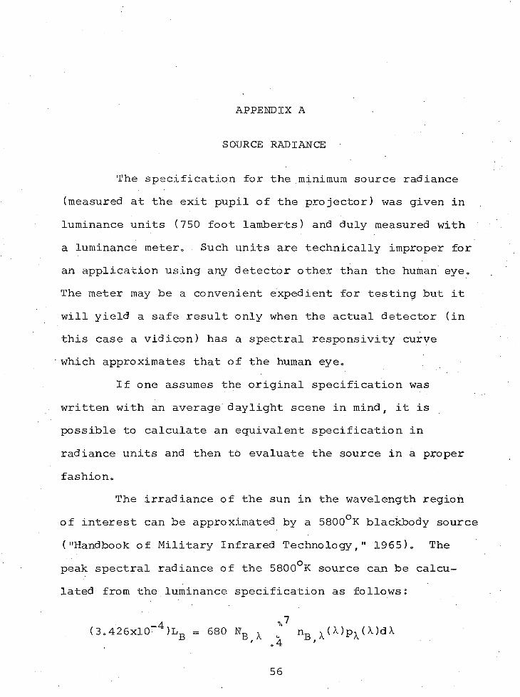
The irradiance of the sun in the wavelength region of interest can be approximated by a 5800°K blackbody source ("Handbook of Military Infrared Technology," 1965). The peak spectral radiance of the 5800°K source can be calculated from the luminance specification as follows:
4 .7(3.426x10 )Lb = 680 Nb x j nB x ( M p x (X)dX
56.
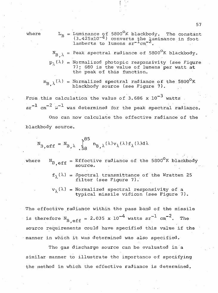
57where Lg = Luminance of 5800°K blackbody„ The constant
(3.425x10“^) converts the luminance in foot lamberts to lumens sr“ cm“ „
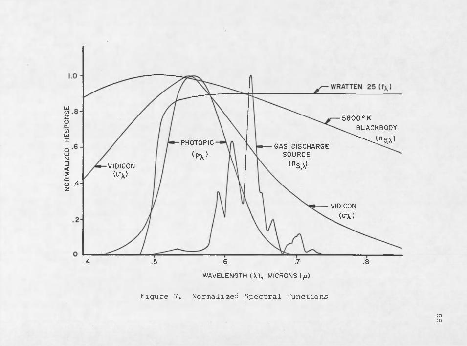
Ng -y = Peak spectral radiance of 5800°K blackbody.(X) = Normalized photopic responsivity (see Figure
7); 680 is the value of lumens per watt at the peak of this function.
nB X = Normalized spectral radiance of the 5800°K ' blackbody source (see Figure 7).
— 3From this calculation the value of 3.686 x 10 watts __2 2 — 1sr cm |-i was determined for the peak spectral radiance.
One can now calculate the effective radiance of the blackbody source.
.85V e f f = HB,X _{s nB,X(X)vX(X)fX(X)aX
where N f „ = Effective radiance of the 5800°K blackbody 'e source.
f^(X) = Spectral transmittance of the Wratten 25 filter (see Figure 7).
v^(X) = Normalized spectral responsivity of atypical missile vidicon (see Figure 7).
The effective radiance within the pass band of the missileis therefore ND ^ = 2.035 x 10~^ watts sr-"*" cm- = The B,effsource requirements could have specified this value if the manner in which it was determined was also specified.
The gas discharge source can be evaluated in a similar manner to illustrate the importance of specifying the method in which the effective radiance is determined.
NO
RMA
LIZE
D R
ESPO
NSE 5800°K
BLACKBODY
\ J nB,X)PHOTOPIC
(px)GAS DISCHARGE
SOURCE
(n S1X)VIDICON(u-\)
.4-
VIDICON
(U-X)
.4 .5 .6 .7 .8WAVELENGTH (X) , MICRONS (fi)
Figure 7. Normalized Spectral Functions
inCD
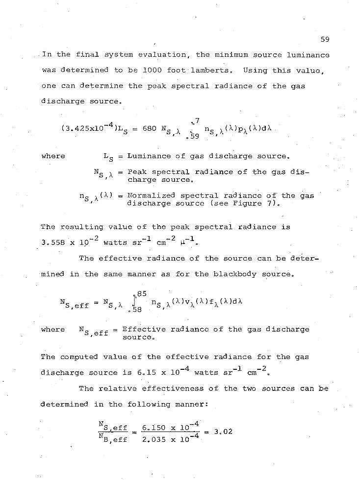
59In the final system evaluation, the minimum source luminance was determined to be 1000 foot lamberts. Using this value, one can determine the peak spectral radiance of the gas discharge source.
_A o 7(3.425x10 )LS = 680 Ng x j ns x (X)px(X)dX
where Lg = Luminance of gas discharge source.Ng x = Peak spectral radiance of the gas dis-
' charge source.ng x (X) = Normalized spectral radiance of the gas
' discharge source (see Figure 7).
The resulting value of the peak spectral radiance is 3.558 x 10"* watts sr-"*" cm-^
The effective radiance of the source can be determined in the same manner as for the blackbody source.
85••s.eff = HS,X nSiX( ^ v x (X)fx (»dX
where eff = Effective radiance of the gas discharge' source.
The computed value of the effective radiance for the gas discharge source is 6.15 x lO-^ watts sr-"*" cm~^.
The relative effectiveness of the two sources can be determined in the following manner:
NS,eff 6.150 x 10“ 4 0 _ -----— — ---r = 3.02B.eff 2.03 5 x 10
60Therefore, the gas discharge source exceeds the minimum source requirements by a factor of 3.02. This is a significantly different value than that which would be obtained by taking a ratio of the corresponding luminance values.
LS 1000Lb - 750 - l o 3 3
In this example, the use of the improper photometric units produced a conservative result. In another example the results could have an opposite result and the consequences could be serious.
REFERENCES
"Design Specification SIMFAX MAVERICK Target ProjectorSubsystem," Hughes Aircraft Co. No. DS31071-001, Canoga Park, Calif., 1969.
"Handbook of Military Infrared Technology," Government Printing Office, Washington, 1965.
Jackson, J. J., "SIMFAX/MAVERICK Motion Picture Report,"Hughes Aircraft Co. Interdepartmental Correspondence No. 2387.00/101, Tucson, Ariz., 1969.
Keihner, J. K., "SIMFAX Slide Report," Hughes Aircraft Co. Interdepartmental Correspondence No. 2342.2/044, Canoga Park, Calif., 1969.
Lange, A. S., "Performance Data: SIMFAX Versus Flight Test," Hughes Aircraft Co. Interdepartmental Correspondence No. 2199.1/87, Canoga Park, Calif., 1971.
Peterson, R. W.# "SIMFAX Target Simulator Servo Performance Tests," Hughes Aircraft Co. Interdepartmental Correspondence No. 2342.1/55, Canoga Park, Calif., 1969.
Vandeveire, H. W . , "Change in Average Light Intensity During Zoom Lens Transitions," Hughes Aircraft Co. Interdepartmental Correspondence No. 2387.50/250, Tucson, Ariz., 1969.
61