Embed Size (px)
Citation preview
OPTICAL POWER SPLITTER BASED ON MULTIMODE
INTERFERENCE (MMI)
ABDULAZIZ MOHAMMED ALI AL-HETAR
A project report submitted in partial fulfillment of
the requirements for the award of the degree of
Master of Engineering
(Electrical-Electronics and Telecommunications)
Faculty of Electrical Engineering
Universiti Teknologi Malaysia
MAY 2007

iv
DEDICATION
Especially dedicated to my beloved parents, my wife, my daughters
Aya and Doa’a, and all my family members for their support.

v
ACKNOWLEDGEMENT
In the name of ALLAH, the Most Beneficent, the Merciful.
Foremost, all praise to ALLAH for the incredible gift endowed upon
me and for give me the health and strength to pursue with this study
and enable me to prepare this thesis.
I deeply appreciate the inspirations and guideline that I have
received from my supervisor Assoc. Prof. Dr. Norazan bin Mohd
Kassim for his personal kindness, skill, patience, valuable advice and
encouragement throughout this project.
I would like take this opportunity to thanks Dr. Haniff for his
helpful and fruitful discussion during this work.
I would also like to thank my parents and my wife for their
moral support on me.
In the, again all praise for the Almighty ALLAH SWT for his
blessings and uncountable awards toward me in spite of all of my
weaknesses and serious faults. Hundreds of millions Darood on our
Holy Prophet Mohamed (Peace upon Him).
vi
ABSTRACT
The challenge in optical access networking is to bring optical
fibers as close to the end-users as possible. One way to realize this
economically is to employ the passive devices. Therefore, it is
necessary to use plenty of passive optical power splitters in the
central office for distribution purposes. Some of the important
characteristics of such splitter are low loss, compactness, and a low
price. To achieve this description fully, Multimode Interference (MMI)
optical power splitters based on self-imaging meet all these
requirements, with considering the ability to optimize the
performance of optoelectronic device over range of operational
parameters. These parameters are important to reduce device length
and provide increase component density. Mathematical model was
used in MATLAB software and verified it by BPM-CAD to design and
optimize 1X2, 1X4, 1X8, 1X16 and 1X32 power splitter based on
MMI.

vii
ABSTRAK
Cabaran rangkaian laluan optik adalah di dalam pendekatan
gentian optik dengan pengguna. Satu daripada cara ekonomi untuk
merealisasikannya adalah dengan menggunakan peranti pasif. Oleh
itu, adalah perlu untuk menggunakan banyak pemisah punca kuasa
optik di dalam pejabat utama bagi tujuan penyebaran Sebahagian
daripada ciri-ciri penting pemisah tersebut adalah sedikit
kehilangan, padat dan harga yang murah. Untuk memenuhi apa
yang dinyatakan di atas, pemisah punca kuasa optic gangguan
pelbagai mod (MMI) berasaskan gambaran diri perlu memenuhi
semua keperluan, dengan mengambil kira pengoptimuman
keupayaan peranti optoelektronik alam julat parameter operasi.
Parameter ini adalah penting untuk mengurangkan panjang peranti
dan menyediakan peningkatan ketumpatan komponen. Suatu model
matematik yang menggunakan perisian MATLAB dan telah disahkan
oleh BPM-CAD untuk mencipta dan mengoptimumkan penggunaan
IX2, IX4, IX8, IX16 dan IX32 pemisah punca kuasa berdasarkan MMI.

LIST OF CONTENTS
CHAPTER TITLE PAGE
TITLE
DECLARATION
DEDICATION
ACKNOWLEDGMENT
ABSTRACT
ABSTRAK
LIST OF CONTENTS
LIST OF TABLES
LIST OF FIGURES
LIST OF SYMBOLS
LIST OF ABBREVIATIONS
ii
iii
iv
v
vi
vii
viii
xi
xii
xvi
xviii
1 INTRODUCTION
1.1 Background 1
1.2 Problem Statement 3
1.3 Objective Of The Project 4
1.4 Scope Of The Project 4
1.5 Methodology Of The Project 4
2 OPTICAL WAVEGUIDE

ix
2.1 Introduction 6
2.2 Optical Waveguide 7
2.2.1 Introduction 7
2.2.2 Electromagnetic Analysis Of The
Planar Waveguide 8
2.2.3 The Longitudinal Wavevector:β 11
2.2.4 Eigenvalues For The Slab Waveguide 12
2.2.5 The Symmetric Waveguide 13
2.2.6 Effective Index 15
2.3 Materials 16
2.4 S-Bend 17
3 MULTIMODE INTERFERENCE (MMI) PRINCIPLE
3.1 Introduction 19
3.2 The Self-Imaging Principle 20
3.3 Multimode Waveguide 20
3.3.1 Number Of Guided Modes In
A Waveguide 21
3.3.2 Propagation Constant 22
3.3.3 FIELD Distribution Inside Waveguide 24
3.3.3.1 General Interference 27
3.3.3.2 Symmetric Interference 29
3.4 Cascaded Multimode Interference 29
4 MATHEMATICAL MODEL
4.1 Introduction 31
4.2 Model Propagation Analysis 32
4.2.1 Guided Modes 32

x
4.2.2 Fields in the MMI Waveguide 36
4.3 Summary 41
5 SIMULATION BY BPM-CAD
5.1 Introduction 43
5.2 Waveguide Coupler 43
5.3 Guide Mode 45
5.4 Simulation 48
5.5 Analysis 57
5.6 Cascade MMI 60
6 CONCLUSIONS AND FUTURE WORK
6.1 Conclusions 62
6.2 Future Work 64
REFERENCES 65
APPENDICES A-C 68 - 77

xi
LIST OF TABLES
TABLE NO. TITLE PAGE
2.1 Classification of optical waveguides according
to the number of dimensions 7
2.2 Refractive indices for common materials 17
4.1 The maximum waveguide width before another
mode becomes supported for a waveguide with
nf = 3.45189744 and nc = 3.36755329. 33
4.2 Results of mathematical model for 1x2, 1x4, 1x8,
1x16 and 1x32 power splitter based on MMI 41
5.1 Gap between two waveguides vs. amount of
coupling power 45
5.2 Comparison among (Soldano and Pennings, 1995)’s
formula, our mathematical model and the optimum
length by BPM-CAD 58

xii
LIST OF FIGURES
FIGURE NO. TITLE PAGE
1.1 Distribution the fiber to the home 2
2.1 The planar slab waveguide consists of three
materials; the index of refractive (nf) is larger
than the surrounding substrate (ns) and
cover (nc) indices. 8
2.2 Transverse electric (TE) and Transverse
magnetic(TM) configuration A cross indicates
the field entering the page 9
2.3 β and k are the longitudinal and transverse
component, respectively, of the wavevector K 11
2.4 This ray and wave picture shows the
electromagnetic field as a function of β 12
2.5 The symmetric waveguide 14
2.6 A buried dielectric waveguide can be
decomposed into two spatially orthogonal
waveguide: a horizontal and a vertical slab
waveguide 15

xiii
2.7 Geometry of the s-bend waveguide 18
3.1 Two-dimensional representation of a step-index
multimode waveguide; (effective) index lateral
profile (left), and top view of ridge boundaries
and coordinate system (right) 22
3.2 Example of amplitude-normalized lateral field
profiles . Corresponding to the first 7 guided ( )vE x
modes in a step-Index multimode waveguide 26
3.3 Multimode waveguide showing the input field
a mirrored single image at( ,0E x ) ( )3Lπ , a direct
single image at ( )2 3Lπ . And tow-fold images at
(1 32
)Lπ and (3 32
)Lπ 28
3.4 Structure of the cascaded 1X 2 splitter 30
4.1 Electrical field profiles ( yE ) for symmetric TE modes for
a given structure of MW =14.3 mμ ,λ =1.55 mμ ,
fn =3.4519, = 3.3675. cn yE has been normalized
to1 and x-axis in m 35
4.2 Electrical field profiles ( yE ) for symmetric TE modes
together for a given structure of
MW =14.3 mμ ,λ =1.55 mμ , fn =3.4518, = 3.3675. cn
yE has been normalized to1 and x-axis in m 36
4.3 General shape of 1xN power splitter based MMI 37

xiv
4.4 Normalize field intensity at the beginning and ending
of1x2MMI coupler 37
4.5 Normalize field intensity at the beginning and ending
of1x4MMI coupler 38
4.6 Normalize field intensity at the beginning and ending
of1x8MMI coupler 39
4.7 Normalize field intensity at the beginning and ending
of1x16 MMI coupler 40
4.8 Normalize field intensity at the beginning and ending
of1x32 MMI coupler 41
5.1 The index profile of two slab waveguides separated
by d 44
5.2 Electrical field profiles ( yE ) for symmetric TE modes for
a given structure of MW =14.3 mμ ,λ =1.55 mμ ,
fn =3.4519, = 3.3675. cn yE has been normalized to 1
and x-axis in mμ 47
5.3 yE E field profiles for symmetric TE modes together for
a given structure of MW =14.3 mμ ,λ =1.55 mμ ,
fn =3.4518, = 3.3675. cn yE has been normalized to 1
and x-axis in m 47
5.4 Schematic layouts of MMI splitters:
(a) 1×2, (b) 1×4, (c) 1×8, (d) 1×16, (e) 1 x 32 51

xv
5.5 BPM-CAD analyses of MMI optical splitters:
(a) 1×2, (b) 1×4, (c) 1×8, (d) 1×16, (e) 1×32 53
5.6 Excess loss and imbalance versus length of MMI
section with λ =1.55 mμ for (a) 1X2 at width = 14.3 mμ ,
(b) 1X4 at width= 28.61 mμ , (c) 1X8 at width=49.05 mμ ,
(d) 1X16 at width=100.145 mμ and (e) 1X32 at width=
202.335 mμ 57
5.7 Structure of the cascaded 1X 2 splitter 61
5.8 BPM-CAD analyses of cascade MMI 61

xvi
LIST OF SYMBOLS
SYMBOL DESCRIPTION
β - Propagation coefficient
rε - Relative permittivity
oε - Free space permittivity
oμ - Free space permeability
oλ - Optical wavelength in free space
c - Speed of light in free space
γ - Attenuation coefficient
K - Transverse wavevector
E - Electric field
H - Magnetic field
P - Power carrier in waveguide
fn - Refractive index for the core
cn - Refractive index for the clad
effn - Effective refractive index
- Vacuum wavevector ok
cR - Curvature radius
O - S-bend offset
ω - Angular frequency

xvii
eh - Effective width of the multimode region
h - Physical width of the multimode region
πL - The beat length

xviii
LIST OF ABBREVIATIONS
1D - One-Dimensional
2D - Two-Dimensional
3D - Three-Dimensional
AlGaAs - Aluminium Gallium Arsenide
BPM - Beam Propagation Method
EIM - Effective index method
FTTH - Fiber to the home
GaAs - Gallium arsenide
InGaAsP - Indium Gallium Arsenide Phosphide
InP - Indium Phosphide
MMI - Multi-mode interference
PDS - Passive double star
PICs - Photonic integrated circuits
PL - Propagation Loss
SiO2 - Silica- Silicon Dioxide TE - Transverse Electric
TM - Transverse Magnetic
WDM - Wavelength divisions multiplex

xix
LIST OF APPENDICES
APPENDIX TITLE
A MATLAB code solves for the longitudinal
propagation constants, β, of the guided modes
of a waveguide using the Newton-Raphson
method 68
B MATLAB code Describe the electrical field
intensity for each mode 73
C MATLAB code Describe the electrical field
intensity for the input and the each output
ports after a certain length from the input port 77

CHAPTER 1
INTRODUCTION
1.1 Background
The world we live in today requires communication on many
levels, the most basic of which is human to human. Indeed invention
of the telegraph and the telephone were the answers to this need that
changed our world and resulted in the creation of widespread
telecommunication network. A similar revolution has occurred in
electronics computing devices that have resulted in the need for
communication from computer to computer. An ever increasing
demand for the acquisition, processing and sharing of information
concerning the world and its future course, today, these needs are
echoed in the demand for higher bandwidth in telecommunication
network and similarly in computing as a demand for higher
processing speeds.
Today’s evolving telecommunication networks are increasingly
focusing on flexibility and reconfigurability, which requires enhanced
functionality of photonic integrated circuits (PICs) for optical
communications. In addition, modem wavelength demultiplexing
(WDM) systems will require signal routing and coupling devices to
have large optical bandwidth and to be polarization insensitive. Also
small device dimensions and improved fabrication tolerances are

2
required in order to reduce process costs and contribute to large-
scale PIC production.
The challenge in optical access networking is to bring optical
fibers as close to the end-users as possible that called Fiber to the
home (FTTH). One way to realize this economically is to employ the
passive double star (PDS) topology [I]. Therefore, it is necessary to use
plenty of passive optical power splitters in the central office for
distribution purposes as depicted in Figure 1.1. Some of the
important characteristics of such splitter are low loss, compactness,
compatibility with optical single-mode fibers, uniform distribution of
the output power on the output waveguides and a low price.
Figure 1.1: Distribution the fiber to the home.
A power splitter 1×2 is usually a symmetric element which
equally divides power from a straight waveguide between two output
waveguides. The simplest version of a power splitter is the Y-branch,
which is easy to design and relatively insensitive to fabrication
tolerances. Nevertheless, the curvature radii of the two branches, as
3
well as the junction, must be carefully designed in order to avoid
power losses. Also, if the two branches are separated by tilted
straight waveguides, the tilt angle must be small, typically a few
degrees [2].
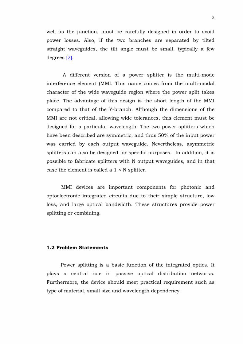
A different version of a power splitter is the multi-mode
interference element (MMI. This name comes from the multi-modal
character of the wide waveguide region where the power split takes
place. The advantage of this design is the short length of the MMI
compared to that of the Y-branch. Although the dimensions of the
MMI are not critical, allowing wide tolerances, this element must be
designed for a particular wavelength. The two power splitters which
have been described are symmetric, and thus 50% of the input power
was carried by each output waveguide. Nevertheless, asymmetric
splitters can also be designed for specific purposes. In addition, it is
possible to fabricate splitters with N output waveguides, and in that
case the element is called a 1 × N splitter.
MMI devices are important components for photonic and
optoelectronic integrated circuits due to their simple structure, low
loss, and large optical bandwidth. These structures provide power
splitting or combining.
1.2 Problem Statements
Power splitting is a basic function of the integrated optics. It
plays a central role in passive optical distribution networks.
Furthermore, the device should meet practical requirement such as
type of material, small size and wavelength dependency.

4
1.3 Objective of the Project: The main objective of this project is to determine the
specification of the optical power splitter based on MMI coupler to
achieve acceptable power splitter design.
1.4 Scope of the project
In order to achieve the objective of this project, the following scope of
work has been identified which comprises of:
- A mathematical model using numerical analysis was
formulated to calculate the optimum width and length of the
1x2, 1x4, 1x8, 1x16, and 1x32 power splitter based on MMI
and plot electric field intensity for input and each output
signal.
- Simulate of the 1x2, 1x4, 1x8, 1x16, and 1x32 power splitter
based on MMI by BPM-CAD.
1.4 Methodology of the Project
To carry out this project, the following methodology is designed:
• Build up the our mathematical model in Matlab software to
design 1X2, 1X4, 1X8, 1X16, and 1X32 power splitter based on
multimode interference(MMI), which includes the following
tasks:
o Get the eingenvalues for propagation coefficient.

5
o Find the electrical field intensity for each mode inside the
waveguide.
o Determine the dimension of the device according to:
- The numbers of output port.
- Type of materials.
- Wavelength.
o Find the output optical power for each port and mention
of the Excess loss and Imbalance.
• Use the approximate formula (Soldano’s formula) to get
propagation constant and find all parameters as previous point.
o Get the eigenvalues for propagation coefficient.
o Find the electrical field intensity for each mode inside the
waveguide.
o Determine the dimension of the device according to:
- The numbers of output port.
- Type of materials.
- Wavelength.
o Find the output optical power for each port and mention
of the Excess loss and Imbalance.
• Simulate all those devices by BPM-CAD to verify our
mathematical model and compare with approximate formula.