Embed Size (px)
Citation preview

OPTICAL NETWORKS

2

OP
TIC
AL S
YS
TE
MS
3
TYPE DESCRIPTION PAGE
OPTO XFP Modular optical platform based on XFP 4
OT DWDM Optical External Modulated Transmitter 1550nm, standalone 14
OA Erbium Doped Fiber Amplifier 1550nm „EDFA“ 16
OT 1131 Optical Direct Modulated Transmitter 1310nm 18
OR 801 Optical Forward Path Receiver 19
OR 203 Optical Return Path Receiver 20
OR 204 Optical Return Path Receiver RFoG 21
Product Overview Optical Nodes 22
ONH RFoG Micro Node - Plus 25
ONB Mini Fibre Node 29
ONC Medium Fibre Node for HFC/FTTX 34
ONS Segmentierbares Fibre Node 2x2 for HFC 38
OTC Optical CATV/SAT-IF Transmitter 40
ORC Optical CATV/SAT-IF Receiver 42
OCP-SC Optical PLC Splitter 44
OWDM-SC Optical Wavelength Division Multiplexer 45
O-MISO Optical Repeater 46
OPTO PAD Optical OMI Measuring Device OptoPAD 47
OCT Optical Cleaning Kit 47
OMPC Optical Fibre Patch Cord 48
OATN Optical Attenuator 48
OPM Optical Power Meter 49
OLS Optical Light Source 49
FTTx Applications RFoG Network System 50

4
O XFP Chassis - optical Transmitter
OPTO XFP SERIES AT A GLANCE
OT XFP pluggable Modules
Broadcast
OT XFP pluggable Modules
Narrowcast
OA XFP pluggable Modules
optical ampliier
O XFP host system
OT XFP 1550 04
OT XFP 1550 07
OT XFP 1550 07-H
OT XFP DWDM
OT XFP DWDM-S
OA XFP DWDM
OT XFP PS-AC
OT XFP PS-DC
Type Description
5700 2689
5700 2686
5700 2687
5700 2920
5700 2688
5700 2919
5700 2813
5700 2691
57002692
Article-no.
Host system, XFP-RF Transmitter, 1RU, 10 XFP-RF ports
XFP-RF Pluggable TX-Module, Broadcast 1.56µm, 1.2GHz, +4dBm, SBS 14 dBm
XFP-RF Pluggable TX-Module, Broadcast 1.56µm, 1.2GHz, +7dBm, SBS 14 dBm
XFP-RF Pluggable TX-Module, Broadcast 1.56µm, 1.2GHz, +7dBm, SBS 18 dBm
XFP-RF Pluggable TX-Module, Wavelength-Tunable, QAM, +1.2GHz, +5 dBm, 43 DWDM
XFP-RF Pluggable TX-Module, Wavelength-Tunable, QAM, +1.2GHz, +7 dBm, 16 DWDM
XFP-RF Pluggable EDFA-Module
Power supply, AC 105-264 V
Power supply, DC 36-75 V
External modulated
transmitter 1550nm
External modulated
transmitter, tunable
wavelength DWDM
Optical ampliier module
+17 dBm,
all DWDM wavelengths

OP
TIC
AL S
YS
TE
MS
5
LESS SPACE - MORE VISION
XFP HOST SYSTEM CHASSIS O XFP Chassis
PRODUCT FEATURES
ll High-Density: 10 ports for 10 XFP-RF transmitters in 1 RU chassis
ll Individual configuration of OMI, RF amplification, operating mode and
SBS status for each of the 10 modules
ll Energy Efficient: maximally 5W per module
ll User-friendly web browser interface to set up and configure transmitters
ll 10 x 75 Ω RF inputs on the rear of the chassis
ll Two physically separated Ethernet SNMP ports on front and rear
ll USB port for future interface applications
ll Option for single or dual power supplies; AC and DC
ll Field-Replaceable Cooling Fan
ll Mounts into standard 19- inch racks
ll Complies with the SCTE HMS HE Optics management Information Base
(MIB) Specifications
Delta`s XFP Chassis is speciically designed around the new XFP trans-
mitter module.
The reduction of rack-spacing and power consumption in the hea-
dend is more than half in comparison to today`s technologies.
Up to 10 XFP-Modules can be deployed in this 1 rack
unit high chassis and consume less than 60 W together.
An embedded web server in the chassis allows transmitter mo-
dules to be conigured with a user-friendly graphical interface
through one of the two Ethernet SNMP ports. An element ma-
nagement system can remotely monitor and control the trans-
mitter modules by connecting the chassis to an IP network.
APPLICATIONS
ll 50 MHz to 1218 MHz RF- over Fiber applications
ll C- and L-Band Transport and Distribution
ll All-Digital QAM networks
ll Standard HFC- and RFoG networks
ll DOCSIS 3.1 compatible
ll Broadcast and Narrowcast services
O XFP Chassis
Product Description
5700 2689
Article number
Chassis, XFP-RF transmitter, 1RU, 10 XFP-RF ports
The chassis can be powered with either one AC power supply or one DC
power supply in the rear of the chassis. For redundancy, a second power
supply can be utilized. For complete powering redundancy in headends
or hubs, one AC power supply and one DC power supply can be used.

6
TECHNICAL SPECIFICATIONS
Key Advantages: ll High Density: 10 transmitters per rack-unit
ll Power consumption per transmitter less than 5 W
ll Redundant powering capability
ll User-friendly web browser coniguration tool
RF Bandwidth
RF Input level
RF Flatness
Return loss
CSO/ CTB
Link noise igure
RF Input connection
RF Test point
Dimensions
Operating Temperature Range
Storage Temperature Range
Power Consumption
Communications interfaces
Indicators
AC Power Supply
DC Power Supply
50 MHz to 1.2 GHz
80 dBµV
+/- 1.5 dB
>18 dB
>60 dB
<20 dB
standard F-connector, 75 Ω
Available for each Tx-Module
449 mm (W) x 378 mm (D) x 44.5 mm (H)
0°C - 50°C
-40°C - 85°C
60 Watts, max. (with 10 XFP modules)
Ethernet SNMP, RJ-45 on front panel
Ethernet SNMP, RJ-45 on rear panel
USB port on front panel (future use)
LED for each transmitter port(10)
Summary LED`s for chassis and power supply status
105 – 264 Vrms, auto-sensing; 47 – 63 Hz
36 – 75 Vdc
Parameter Value

OP
TIC
AL S
YS
TE
MS
7
1.2 GHZ OPTO XFP TRANSMITTER OT XFP 1550 04 / OT XFP 1550 07
PRODUCT FEATURES
ll DOCSIS 3.1 compatible with operating bandwidth up to 1218 MHz
ll Mechanical dimensions compliant with 10 Gigabit Small Form Factor
(XFP) host-system
ll Externally modulated, no dispersion compensation required
ll Transmission of up to 79 analogue plus 75 QAM channels
ll Link distance of up to 35 km without optical amplification
ll Transmitter version with +7 dBm and +4 dBm Optical Output Power
ll LC/APC optical connection
ll Power consumption < 3.5W
ll Built- in digital diagnostic functions
ll Compliant with SCTE 195 2013
Delta`s XFP Transmitter is a hot-pluggable optical module that is compli-
ant with SCTE interface speciications.
The external modulated XFP transmitter is in a very small package. It can
be fully loaded with 79 analogue AM-VSB channels
plus 75 Digital QAM channels. The small XFP module signiicantly in-
creases the density and reduces power consumption for downstream
transmitter which can be integrated into today`s Hybrid-Fiber Coaxial
(HFC) optical platforms and tomorrow`s broadband infrastructure equip-
ment.
APPLICATIONS
ll Hybrid Fiber Coaxial (HFC) cable access networks
ll Transmission of broadcast services
ll RFoG technology
OT XFP 1550 04
OT XFP 1550 07
OT XFP 1550 07-H
Product Description
5700 2686
5700 2687
5700 2920
Article number
XFP-RF Pluggable TX-Module, Broadcast 1.56µm, 1.2GHz, +4dBm, SBS 14 dBm
XFP-RF Pluggable TX-Module, Broadcast 1.56µm, 1.2GHz, +7dBm, SBS 14 dBm
XFP-RF Pluggable TX-Module, Broadcast 1.56µm, 1.2GHz, +7dBm, SBS 18 dBm (high SBS value)
The OT XFP 1550 04 and OT XFP 1550 07 transmitter modules can
complement or replace today`s legacy 1310 nm and 1550 nm
broadcast transmitters.
Since the wavelength is at 1.55 µm, the optical signal can be multiplex-
ed with a legacy 1.31 µm optical signal to cost-effectively double the
capacity of the iber to the nodes.
Due to lower iber loss at 1.55 µm, the 7 dBm transmitter can transport
signals to a node over iber up to 35 km regardless of optical dispersion
thanks to the modern integrated external modulation technology. Even
further distances can be bridged with an additional standard optical am-
pliier EDFA.

8
Notes:
1. Maximum total power value is speciield across the full temperature and voltage range
2. After internal AC coupling
3. Or open circuit
4. VCC2 (+1.8 V) is not implemented from the XFP MSA Speciication
5. SBS suppression measured with the following link: transmitter through EDFA, launch power of +14 dBm,
20 km of iber, 0 dBm input power into receiver
6. SBS suppression measured with the following link: transmitter through EDFA, launch power of +13 dBm,
65 km of iber, 0 dBm input power into receiver. SBS suppression up to 20 dBm is possible
TECHNICAL SPECIFICATIONS
Power Supply
+3.3 V Voltage, Analog
+3.3 V Voltage, Digital
+5 V Voltage
-5.2 V Voltage
Supply Current – Vcc3 supply
Supply Current – Vcc5 supply
Supply Current – Vee5 supply
Module total power dissipation
RF
Composite RF Input Level
Input differential impedance
Transmit Disable Voltage
Transmit Enable Voltage
RF Bandwith
RF Flatness, peak to peak
50-1003 MHz
50-1218 MHz
RF Input Return Loss, 50-1003 MHz
Optical
Output Opt. Pwr: 9/125 SMF
OT XFP 1550 07
OT XFP 1550 04
Optical Wavelength Range
SBS Supression
through 20 km of iber
through 65 km of iber
VCC3_ANALOG
VCC3_DIGITAL
VCC5
VEE5
Icc3
Icc5
Iee5
P
RFin
Rin
VD
VEN
POUT
Parameter Symbol Min Typ Max Unit Ref.
3.13
3.13
4.75
-5.46
107,75
2.0
GND
50
16.0
6.75
3.75
1555
+14
+13
110
100
3.46
3.46
5.25
-4.75
500
500
50
3.5
113,75
Vcc
GND+0.8
1218
1.0
1.5
7.75
4.75
1565
V
V
V
V
mA
mA
mA
W
dBµV
Ω
V
V
MHz
dB
dB
dB
dBm
dBm
nm
dBm
dBm
4
4
4
4
1
2
3
5
6

OP
TIC
AL S
YS
TE
MS
9
WAVELENGTH TUNABLE 1.2 GHZ OT XFP DWDM TRANSMITTER OT XFP DWDM
PRODUCT FEATURES
ll DOCSIS 3.1 compatible with operating bandwidth up to 1218 MHz
ll Mechanical dimensions compliant with 10 Gigabit Small Form Factor
(XFP) host-system
ll All-Digital 256 QAM loading up to 154 carriers
ll Externally modulated, no dispersion compensation required
ll Wavelength-Tunability across entire C-band at 100 GHz spacing
ll Link distances up to 60 km
ll LC/APC optical connection
ll Power consumption < 3.5 W
ll Built- in digital diagnostic functions
ll Compliant with SCTE 195 2013
Delta`s XFP Transmitter is a hot-pluggable optical module that is compli-
ant with SCTE interface speciications.
The external modulated XFP transmitter is in a very small package. It can
be fully loaded with 154 digital QAM channels.
The small XFP module signiicantly increases the density and reduces
power consumption for downstream transmitter which can be integrated
into today`s Hybrid-Fiber Coaxial (HFC) optical platforms and tomorrow`s
broadband infrastructure equipment.
APPLICATIONS
ll Hybrid Fiber Coaxial (HFC) cable access networks
ll 1550 nm Broadcast with DWDM Narrowcast overlay architectures
ll All-Digital QAM networks
OT XFP DWDM
OT XFP DWDM-S
Product Description
5700 2688
5700 2919
Article number
XFP-RF Pluggable TX-Module, Wavelength-Tunable, QAM, +1.2GHz, +5 dBm, 43 DWDM
XFP-RF Pluggable TX-Module, Wavelength-Tunable, QAM, +1.2GHz, +7 dBm, 16 DWDM
The wavelength of the transmitter can be tuned by the user within 500
ms. Each DWDM wavelength within the C-band can be selected.
This increases operational eficiencies in deploying DWDM networks
and reduces inventory of transmitters at different ixed wavelengths.
Wavelength-Tunability also opens the possibility of novel HFC architec-
tures that can dynamically route services and increases bandwidth ca-
pacity in the cable operator`s access network.

10 7
Notes:
1. Maximum total power value is speciied across the full temperature and voltage range
2. After internal AC coupling
3. Or open circuit
4. VCC2 (+1.8 V) is not implemented from the XFP MSA Speciication
5. Corresponds to approximately 0.8 nm
6. X= Speciied ITU Grid Wavelength. Wavelength stability is achieved within 10 seconds of power up
7. SBS suppression measured with the following link: XFP-Transmitter, EDFA, launch power of +14 dBm, 20 km
of iber, 0 dBm input power into receiver. Transmitter loaded with 153 channels of QAM. SBS dither is enabled
on the transmitter
TECHNICAL SPECIFICATIONS
Power Supply
+3.3 V Voltage Analog
+3.3 V Voltage, Digital
+5 V Voltage
-5.2 V Voltage
Supply Current – Vcc3 supply
Supply Current – Vcc5 supply
Supply Current – Vee5 supply
Module total power dissipation
RF
Composite RF Input Level
Input differential impedance
Transmit Disable Voltage
Transmit Enable Voltage
RF Bandwidth
RF Flatness, peak to peak
50-1003 MHz
50-1218 MHz
RF Input Loss, 50-1003 MHz
Optical
Optical Output Power 9/125 SMF
Optical Wavelength Range
Optical Wavelength Spacing
Transmitter Center Wavelength –
Beginning of Life
Transmitter Center Wavelength –
End of Life
Wavelength Tuning Time
SBS Suppression
VCC3_ANALOG
VCC3_DIGITAL
VCC5
VEE5
Icc3
Icc5
Iee5
P
RFin
Rin
VD
VEN
POUT
λ λ
Parameter Symbol Min Typ Max Unit Ref.
3.13
3.13
4.75
-5.46
105,75
2.0
GND
50
16.0
4.75
1529.55
X-25
X-100
+14
108,75
100
100
X
X
0.5
+18
3.46
3.46
5.25
-4.75
500
500
50
3.5
111,75
Vcc
GND+0.8
1218
1.0
1.5
5.75
1563.05
X+25
X+100
3.0
+20
V
V
V
V
mA
mA
mA
W
dBµV
Ω
V
V
MHz
dB
dB
dB
dBm
Nm
GHz
Pm
Pm
seconds
dBm
4
4
4
4
1
2
3
5
6
6
7

OP
TIC
AL S
YS
TE
MS
11
OPTICAL FIBRE AMPLIFIER OA XFP DWDM
PRODUCT FEATURES
ll DOCSIS 3.1 compatible
ll Mechanical dimensions compliant with 10 Gigabit Small Form Factor
(XFP) host-system
ll 980nm pump laser module
ll High output power up to 17 dBm
ll APC (automatic power control) and FLS (forced laser shutdown)
ll LVTTL alarm
ll Low power consumption
ll Compatible with SCTE 195 2013
The small, pluggable OA XFP DWDM is a full-functioning EDFA module
with control circuitry packaged inside. It is totally compatible with the
OPTO XFP host-system in respect of size and pin-map. Due to the
small size and easy installation, the OA XFP DWDM is designed for
single wavelength applications in ibre optic communication systems
in core networks, access networks or CATV networks. The OA XFP
DWDM provides very stable output power of up to 17dBm and a noi-
se igure of 6dB in C-band over a wide operating temperature range.
APPLICATIONS
ll Compatible with DELTAs XFP Host System
ll Optimized for using in connection with OT XFP DWDM
ll Broadcast and narrowcast application
ll Narrowband ampliication in C-band
ll Ampliication of DWDM-wavelengths in DWDM-networks due to
integrated gain equalizer
OA XFP DWDM 5700 2813 XFP EDFA module, 17dBm optical ouput power, ampliication of all DWDM wavelengths
Over I²C all of the alarm-parameters such as output alarm,
bias current, temperature and power supply can be analysed.
Type DescriptionArticle number

12
SOURCE HUB
XFP OVERVIEW

OPTICAL SYSTEMS
13
US
ER

14
OPTICAL EXTERNAL MODULATED TRANSMITTER 1550 nmOT DWDM 1155-2-xx
Applications:
ll Conversion of electrical CATV signals (QAM, AM-VSB, FM) into an optical signal
ll Enables the usage of optical ampliier (EDFA) as booster or repeater in order to
realize large FTTx networks
ll Video overlays in FTTx networks and xPON-application
Features:
ll Adjustable DFB Laser, variable in C-band from 1528.77nm to 1560.61nm
ll Supports Dense Wavelength Division Multiplexing (DWDM)
ll Wavelengths adjustable in an interval of 0.4 nm in C-Band
ll High stability of the wavelengths
ll Narrow spectrum of laser (0.3 MHz)
ll Adjustable SBS-suppression of 13 to 19 dB in 0.1 dB steps
ll Adjustable Optical Modulation Index (OMI)
ll Automatic (AGC) or manual (MGC) control for laser management
ll Outstanding CNR, CSO and CTB values
ll Implemented microprocessor, LCD and LED status display
ll SNMP and web-based monitoring for all parameters
ll OMI, SBS, wavelength AGC and MGC remotely adjustable over WebGUI
ll Redundant power supply
ll Test socket: RF Test -20dB
Typ Article number Optical Output Power (dBm) Number of Ports Setting range (nm)
OT-DWDM-1155-02-09 5700 2428
OT-DWDM-1155-02-11 5700 2539
9 2 1550.92 - 1554.14
11 2 1550.92 - 1554.14

OP
TIC
AL S
YS
TE
MS
15
TECHNICAL SPECIFICATIONS
Performance Index
Min Typ Max
Input wavelength (λ) nm
Full C-Band 1528.77 1560.61
Partial C-Band 1550.92 1554.13
Optical output power dBm 9 11
(at each output)
Number of ports 2
Channels spacing nm 0.4
Tuning speed ms 20
SBS-threshold dB 13 adjustable 19
Side mode suppression ratio
(SMSR) dB 45 50
Relative intensity noise
(RIN) dB -160
Optical return loss >45
Optical connector SC/APC (further on request)
Optical
Features
RF Features
HF bandwidth MHz 47 - 1000/1200
Input level dBµV 70 - 88
Frequency range dB ± 0.75
CNR dB 52.5 PAL-D/60 Ch. 65km Fiber, 0 dBm receiver
CSO, CTB dB <65
Input impedance Ω 75
General Features
SNMP netzwork management RJ45, LAN
WebGUI
Power supply VDC ± 36 ± 48 ± 72
Power consumption W 50
Operating temperature °C -5 22 65
Storage temperature °C -40 85
Relative humidity % 5 55 95
Dimensions mm 482 x 360 x 44 L x B x H
Data Sheet

16
ERBIUM DOPED FIBER AMPLIFIER - EDFA
Applications:
ll Optical ampliication for the wavelength of 1550nm
ll Realization of vast HFC- and RFoG-networks
ll Decentral signal distribution / ampliication in FTTx / xPON-networks
ll CATV-overlay in FTTx und xPON-networks
Features:
ll High optical output power of +18dBm or +21 dBm at each output port (other optical output levels on request)
ll Up to 32 possible optical outputs
ll Integrated optical isolation of the downstream wavelength of 1550 nm and all other possible wavelengths in upstream for the realization of
standard-RFoG, CWDM-RFoG- or GPON-networks
ll Low insertion loss in DS&US and high isolation of DS&US (>50dB)
ll Low noise igure
ll Integrated micro controller and LCD
ll Parameter-Display: input/output optical power, pump-bias, temperature and voltage
ll Supports SNMP monitoring and WebGUI
ll Redundant power supply
ll 19“, 1 HE Rack Unit type
OA 1155-1-18 5700 1613
OA 1155-1-21 5700 1813
OA 1155-4-18 5700 1810
OA 1155-4-21 5700 1809
OA 1155-4-21w 5700 2302
OA 1155-8-21 5700 2426
OA 1155-8-21w 5700 2010
OA 1155-16-21 5700 2427
OA 1155-16-21w 5700 2009
1 18 1
1 21 1
4 18 1
4 21 1
4 21 1
8 21 1
8 21 x x 1
16 21 1
16 21 x x 2
OA 1155-STANDARD - 18/19/21 dB
Type Article number Number of Optical output power GPON optimized* CWDM-RFoG* Rack
outputs at each output (dBm) units
OP
TIC
AL S
YS
TE
MS
17
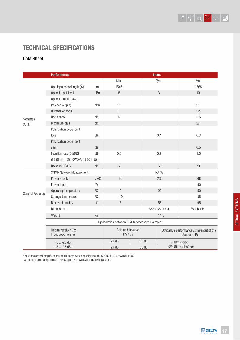
TECHNICAL SPECIFICATIONS
Performance Index
Min Typ Max
Opt. input wavelength (λ) nm 1545 1565
Optical input level dBm -5 3 10
Optical output power
(at each output) dBm 11 21
Number of ports 1 32
Noise ratio dB 4 5.5
Maximum gain dB 27
Polarization dependent
loss dB 0.1 0.3
Polarization dependent
gain dB 0.5
Insertion loss (DS&US) dB 0.6 0.9 1.6
(1550nm in DS, CWDM/ 1550 in US)
Isolation DS/US dB 50 58 70
Merkmale
Optik
General Features
SNMP Network Management RJ 45
Power supply V AC 90 230 265
Power input W 50
Operating temperature °C 0 22 50
Storage temperature °C -40 85
Relative humidity % 5 55 95
Dimensions 482 x 360 x 90 W x D x H
Weight kg 11.3
High Isolation between DS/US necessary. Example:
Return receiver (Rx)
Input power (dBm)
Gain and isolation
DS / USOptical DS performance at the input of the
Upstream-Rx
-8... -28 dBm
-8... -28 dBm
21 dB 30 dB
21 dB 50 dB
-9 dBm (noise)
-29 dBm (noisefree)
* All of the optical ampliiers can be delivered with a special ilter for GPON, RFoG or CWDM-RFoG.
All of the optical ampliiers are RFoG optimized, WebGui and SNMP suitable.
Data Sheet

18
OPTICAL DIRECT MODULATED TRANSMITTER 1310NM
ll Modular optical Transmitter for Cable TV signals (CATV)
ll Cooled 1310nm DFB laser with electronic multi-point-pre-
distortion- keeps intermodulation interference (CTB,CSO) low
ll Microprocessor controlled level control (ALC) for uncomplicated elec-
tric operation with constant transmission parameters
ll Recommended for “Deep Fiber” applications, e.g. HFC Access
networks with small coax clusters and FTTx-networks
ll Flexible and service-friendly through modular construction,
module slots on rear chassis
ll 19” Base unit, 1RU with power supply and 2 slots
for transmitter modules OTM 813-xx
ll Signal connectors on rear chassis, displays and test points on front
chassis
ll Microprocessor controlled and display functions with
alpha-numeric LCD-Display
ll Addressable network management interface for remote control
of modules and base unit compatible with SNMP
ll Alarm and status signalisation with LEDs
Type
Optical output power dBm
Optical wavelength nm
RF frequency range MHz
RF input level dBµV
C/N dB
CTB dB
CSO dB
RF flatness dB
RF impedance Ω
RF input return loss dB
Operating temperature ºC
Overall relative humidity %
Fibre connector
RF connector
NMS-Interface
Operating voltage V~
Power consume W
Laser class
OT 813 / OTM 813-xx
8 / 10 / 12 / 13.5, direct modulated DFB-Laser
1310 ± 20
47 - 870
80 ± 3 (Multiple channel load > 20AM/TV channel
52 (10 km fiber distance, receiver input 0 dBm)
-67
-62
± 0.75
75
> 16 / 47-550 MHz, > 14 / 550-870 MHz
+ 5 ... + 40
40 - 70
SC/APC
F- connectors
RS 232/485, base unit
230 (86 - 264), Switch mode power supply in base unit
50 (Base unit with 2 modules)
1M, DIN EN 60825-1 (2008)
Type OTM 813-10 OTM 813-12 OTM 813-13.5
5700 1323
optical transmitter
module 1310nm,
output power
10 dBm (10mW)
5700 1325
optical transmitter
module 1310nm,
output power
13.5 dBm (22.3mW)
5700 1324
optical transmitter
module 1310nm,
output power
12 dBm (16mW)
Article-No.
Description
5700 1322
optical transmitter
module 1310nm,
output power
8 dBm (6mW))
5700 1321
base unit with
slots for transmit-
ter modules, incl.
power supply
OTM 813-08OT 813

OP
TIC
AL S
YS
TE
MS
19
OPTICAL FORWARD PATH RECEIVER
Type
Operation wavelength (λ) nm
Optical return loss dB
Optical input power dBm
RF frequency range MHz
RF output Level dBµV
C/N dB
CTB dB
CSO dB
Test point optical input V/mW
RF impedance Ω
Test point RF output dB
Operating temperature °C
Overall relative humidity %
Fibre connector
RF connector
Operating voltage V~
Power consumption W
OR 801
1000 - 1600
> 45
-6 ... +3
47 - 862
> 100 (@ 0dBm optical input power, OMI = 4%)
51
< -65
< -62
5
75
-20
+ 5 ... + 40
40 - 70
SC/APC
F-connectors
230 (180-244), Switch mode power supply
20 (Base unit with receiver module)
ll Full optical HFC receiver in 19” single rack unit housing
ll With optical-electrical converter module with low noise pre-Amplifier
ll High output level with low, non-linear distortions (CTB, CSO) through
power doubling output stage
ll Connections for fibre (SC/APC) and RF socket for signal
output on rear chassis
ll Modular construction, consisting of base unit with integrated power
supply and receiver slot
ll Signal connectors on rear chassis, displays and test points on front
chassis
ll DC test point, optical input level (5V/mW) and level
signalization with LED
ll Simple Plug & Play operation
ll Efficient, energy-saving switch-mode power supply
Article-No.
Description
Type OR 801
5700 1328
19” Optical receiver, 1 rack unit, 47 – 862 MHz, -6…+3dBm

20
DELTA Optical return path receiver is designed for converting upstream
optical signal into RF signals at the head-end or remote hubs
ll Modular return path receiver for optical fibre hubs in HFC and FTTx
access networks
ll Optical-electrical converter module and with low noise pre-amplifier
ll 19” Base unit, 1 rack unit (RU) for 3 receiver modules ORM 200
ll High output ability through power doubling output stage
ll Contacting of display and test signals via SUB-D Plug to front panel
of base unit
ll Configurable as “point-to-point” and “point-to-multi-point” links
ll User-friendly and tidy: Signal connectors on rear chassis, displays
and test points on front chassis
Type
Optical wavelength nm
Optical return loss dB
Optical input power dBm
RF frequency range MHz
RF output Level dBµV
C/N dB
CTB dB
CSO dB
Test point optical input V/mW
RF impedance Ω
Test point RF output dB
Operating temperature ºC
Overall relative humidity %
Fibre connector
RF connector
Operating voltage V~
Power consumption W
OR 203 + ORM 200
1000 - 1600
> 45
-6 ... +3
5 - 200
100 (@ 0dBm optical input power, OMI = 4%)
51
< -65
< -62
5
75
-20
+ 5 ... + 40
40 - 70
SC/APC
F-Connectors
230 (180-244)
46 (base unit with receiver module)
OPTICAL RETURN PATH RECEIVER
Article-No.
Description
Type OR 203 ORM 200
5700 1326
19” 1HE, Base unit incl. power supply for
3 return path receiver modules
5700 1327
Optical return path receiver module,
5 - 200 MHz, SC/APC

OP
TIC
AL S
YS
TE
MS
21
5700 1601
return path receiver
1260..1620nm, 4 inputs,
4 RF-outputs,
SC/APC,
80 MHz return path
5700 2922
return path receive
1260..1620nm, 8 inputs,
8 RF-outputs,
SC/APC,
80 MHz return path
OPTICAL RETURN PATH RECEIVER RFoG
DELTA Optical return path receiver is designed for RFoG FTTx applications.
Converting an upstream optical signal into RF signals at the head-end or re-
mote hubs.
ll 4-/8-Port receiver
ll All receivers are packed in a standard 19”,1 RU
ll Band receiver 1260nm – 1620nm
ll Optical input power range -26 dBm to -10 dBm
ll RF output power adjustable from 70 to 100 dBµV
ll Low noise enables DOCSIS 3.1 upstream channel bonding
ll Test / Monitor points for each RF output
ll Front mounted SC/APC connectors
ll Temperature-range: 0°C to +50°C
ll Redundant power supply
Article-No.
Description
Type OR 204 L OR 208 L OR 204 H OR 208 H
5700 2494
return path receiver
1260..1620nm, 4 inputs,
4 RF-outputs,
SC/APC,
204 MHz return path
5700 2923
return path receiver
1260..1620nm, 8 inputs,
8 RF-outputs,
SC/APC,
204 MHz return path
Type
Operation wavelength (λ) nm
Receiving Power dBm
Optical fibre connector
RF bandwidth MHz
RF output power dBµV
Flatness dB
Return loss dB
RF test point/Monitor dB
RF connector dB
Equivalent input noise pA/√Hz
Power supply V~
Power consumption per module W
Operating temperature °C
Dimensions (W x D x H) mm
1260 - 1620
-20 … -12
SC/APC
75 - 95
≤ ± 0.75
16
-20 ± 0.5
F-female
230
max. 3
0 - +50
482 x 310 x 44
OR 204 L / OR 208 L
5-85
0.7
OR 204 H / OR 208 H
5-204
1.0
22
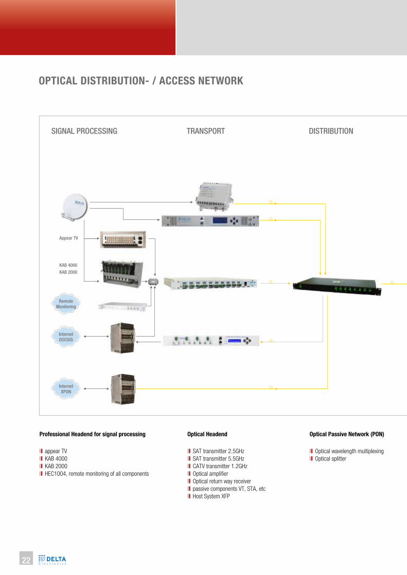
OPTICAL DISTRIBUTION- / ACCESS NETWORK
Professional Headend for signal processing
ll appear TV
ll KAB 4000
ll KAB 2000
ll HEC1004, remote monitoring of all components
SIGNAL PROCESSING TRANSPORT DISTRIBUTION
Optical Headend
ll SAT transmitter 2.5GHz
ll SAT transmitter 5.5GHz
ll CATV transmitter 1.2GHz
ll Optical amplifier
ll Optical return way receiver
ll passive components VT, STA, etc
ll Host System XFP
Optical Passive Network (PON)
ll Optical wavelength multiplexing
ll Optical splitter
Appear TV
KAB 4000
KAB 2000
Internet
XPON
Internet
DOCSIS
Remote
Monitoring

OP
TIC
AL S
YS
TE
MS
23
CELL CURB BUILDING HOME
Optical Nodes
ll AII CWDM wavelengths available
ll Burst mode and CW mode
ll low cost monitoring
ll Green intelligence

24
PRODUCT OVERVIEW OPTICAL NODES
As a specialist for HFC- and RFoG-networks, DELTA Electronics offers a wide range of optical nodes. They are optimized for the individual
applications at different locations. With the smallest optical nodes also a low number of users can be connected to the RFoG-network. Residential
districts can be connected to the optical network with bigger nodes such as the ONB, ONC or ONS in a redundant concept.
The decision for a certain optical node depends on several factors:
ll Level of the maximum RF-loss after the optical node (passive splitters, length of coaxial cable, etc.)
ll Number of ibers for down- and upstream
ll Applied wavelength in both directions
ll Operating mode of the laser (burst- or continuous-mode)
ll Existing DOCSIS standard and DOCSIS operation in upstream (channel bonding)
ll Preferred way of monitoring and or FOSTRA-D (DOCSIS compliant)
ll Remote-control with FOSTRA-F (new RFoG Standard): DS ON/OFF, Burst Mode ON/OFF, Ingress Detection Switch 0 / 6 / 45 dB

OP
TIC
AL S
YS
TE
MS
25
ONH 11xx BF-xx
RFoG MICRO NODE - PLUS
Micronode for RFoG networks, FTTH/FTTB applications
ll Extremely low noise optical receiver
ll Constant RF output level at wide optical input power range
ll OLC function based on optical input power
ll Interstage attenuator and slope
ll Optical input power indicator and monitoring LED’s
ll RF input and output test point
ll Ultra Low noise DFB- laser with isolator in burst mode operation
ll Internal WDM filter US/DS wavelength for RFoG-Application
ll Wavelength available from 1270nm to 1610nm at CWDM grid to avoid
OBI
ll Remote controllable in DS & US due to FOSTRA-F receiver module
Description Optical Micro-Receiver,
1550nm, 40-1006 MHz,
92 dBµV RF-output level
(without return path)
DS: 1310m / 1550nm
US: CWDM
80 dBµV RF-output level
DS: 1310m / 1550nm
US: CWDM
92 dBµV RF-output level
DS: 1310m / 1550nm
US: CWDM
99 dBµV HF-output level
Type ONH 1000 ONH 11xx BSF-xx ONH 11xx BF-xx ONH 11xx B1F-xx

26
Ups
trea
mD
owns
trea
mM
onito
ring
Type
Applications
Compact die-cast housing mm
Weight kg
Fibre connectors
RF connectors
Mains feeding V~/W
Operating temperature °C
Adjustment elements
Internal WDM (Tx / Rx) nm
Optical wavelength nm
Optical input power dBm
Frequency range MHz
Frequency response dB
Optical level control (OLC) dBm
RF output level dBµV
C/N
RF level attenuator dB
RF slope dB
Test point RF output dB
Monitoring optical input dBm
Test point optical input V/mW
DFB Laser / optical power dBm
Laser operation
RF input dynamic range dBµV
Frequency range MHz
RF input level dBµV
RF input level attenuator dB
HEC 1004 Controller
FOSTRA F Control module
ONH 11xx BSF-xx ONH 11xx BF-xx ONH 11xx B1F-xx
FTTH, FTTB, DOCSIS-PON/RFoG
188 x 85 x 50 / IP 20, In-door
0.8
SC/APC
F-female
230 / < 6
-20…+55, free convection
Step Spin Attenuator and Jumper
DS / US
1550 ± 10 / 1310 ± 10
-8…+2, max. +2 dBm optical input power
85…1006
± 0.7
-7…+1 (RF-output level ± 1 dB)
@ -7…+1 dBm, OMI = 4 %, CTB,CSO > 60 dBc
50 dBc @ -3 dBm, OMI 4%
0 / 2 / 4 6 / 8 / 10 (Step Spin Attenuator)
0 / 3 / 6 (Switchable by jumper)
-20 (F-female, external)
Green LED on: input > -10
2 (Inside housing)
3
Burst Mode (Laser “Delay-Time” ≤ 0,8 µsec) SCTE compliant
76…100 (“Laser ON”@ Min. input RF-Level 76 dBµV)
15…65
OMI 15% @ 70 (Att. = 0 dB)
0 / 2 / 4 6 / 8 / 10 (Step Attenuator 2 dB steps), 0 / 10 / 20 dB Jumper Att.
FSK-TX, 868 MHz
FSK Receiver RX : 868 MHz
80 ± 1 92 ± 1 99 ± 1

OP
TIC
AL S
YS
TE
MS
27
Please use the follwoing article numbers when ordering:
VERSIONSONH 11 xx BxF-xx
Frequency range US-wavelength Laser operation, monitoring, RF-output level DS-wavelength Diplexer (MHz)
11: up to 1006 MHz 27: 1270 nm
29: 1290 nm
31: 1310 nm
33: 1330 nm
35: 1350 nm
37: 1370 nm
39: 1390 nm
41: 1410 nm
43: 1430 nm
45: 1450 nm
47: 1470 nm
49: 1490 nm
51: 1510 nm
53: 1530 nm
55: 1550 nm
57: 1570 nm
59: 1590 nm
61: 1610 nm
B: burst and continuous-Mode
1: 99 dBµV
_: 92 dBµV
S: 80 dBµV
F: FSK-monitoring prepared
13: 1310 nm
15: 1550 nm
-: 565 (5-65/85)
85: 585 (5-85/105)
Type Article-No. Remarks
ONH 1000
ONH 1127 BF-15
ONH 1129 BF-15
ONH 1131 BF-15
ONH 1133 BF-15
ONH 1135 BF-15
ONH 1137 BF-15
ONH 1139 BF-15
ONH 1141 BF-15
ONH 1143 BF-15
ONH 1145 BF-15
ONH 1147 BF-15
ONH 1149 BF-15
ONH 1151 BF-15
ONH 1153 BF-15
ONH 1157 BF-15
ONH 1159 BF-15
5700 1708
5700 2225
5700 2226
5700 2227
5700 2228
5700 2229
5700 2230
5700 2231
5700 2232
5700 2233
5700 2234
5700 2235
5700 2236
5700 2237
5700 2238
5700 2239
5700 2240
Optical receiver 92 dBµV, 5-1006 MHz
ONH with 1270 nm in US, 1550 in DS, BIDI-module, 92 dBµV
ONH with 1290 nm in US, 1550 in DS, BIDI-module, 92 dBµV
ONH with 1310 nm in US, 1550 in DS, BIDI-module, 92 dBµV
ONH with 1330 nm in US, 1550 in DS, BIDI-module, 92 dBµV
ONH with 1350 nm in US, 1550 in DS, BIDI-module, 92 dBµV
ONH with 1370 nm in US, 1550 in DS, BIDI-module, 92 dBµV
ONH with 1390 nm in US, 1550 in DS, BIDI-module, 92 dBµV
ONH with 1410 nm in US, 1550 in DS, BIDI-module, 92 dBµV
ONH with 1430 nm in US, 1550 in DS, BIDI-module, 92 dBµV
ONH with 1450 nm in US, 1550 in DS, BIDI-module, 92 dBµV
ONH with 1470 nm in US, 1550 in DS, BIDI-module, 92 dBµV
ONH with 1490 nm in US, 1550 in DS, BIDI-module, 92 dBµV
ONH with 1510 nm in US, 1550 in DS, BIDI-module, 92 dBµV
ONH with 1530 nm in US, 1550 in DS, BIDI-module, 92 dBµV
ONH with 1570 nm in US, 1550 in DS, BIDI-module, 92 dBµV
ONH with 1590 nm in US, 1550 in DS, BIDI-module, 92 dBµV

28
ONH 1161 BF-15
ONH 1127 B1F-13
ONH 1129 B1F-13
ONH 1133 B1F-13
ONH 1135 B1F-13
ONH 1137 B1F-13
ONH 1139 B1F-13
ONH 1141 B1F-13
ONH 1143 B1F-13
ONH 1145 B1F-13
ONH 1147 B1F-13
ONH 1149 B1F-13
ONH 1151 B1F-13
ONH 1153 B1F-13
ONH 1155 B1F-13
ONH 1157 B1F-13
ONH 1159 B1F-13
ONH 1161 B1F-13
ONH 1127 B1F-15
ONH 1129 B1F-15
ONH 1131 B1F-15
ONH 1133 B1F-15
ONH 1135 B1F-15
ONH 1137 B1F-15
ONH 1139 B1F-15
ONH 1141 B1F-15
ONH 1143 B1F-15
ONH 1145 B1F-15
ONH 1147 B1F-15
ONH 1149 B1F-15
ONH 1151 B1F-15
ONH 1153 B1F-15
ONH 1157 B1F-15
ONH 1159 B1F-15
ONH 1161 B1F-15
ONH 1161 B1F-15-85
Type Article-No. Remarks
5700 2112
5700 2241
5700 2242
5700 2243
5700 2244
5700 2245
5700 2246
5700 2247
5700 2248
5700 2249
5700 2250
5700 2251
5700 2252
5700 2253
5700 2254
5700 2255
5700 2256
5700 2257
5700 2258
5700 2259
5700 2260
5700 2261
5700 2262
5700 2263
5700 2264
5700 2265
5700 2266
5700 2267
5700 2268
5700 2269
5700 2270
5700 2271
5700 2272
5700 2273
5700 1957
5700 2675
ONH with 1610 nm in US, 1550 in DS, BIDI-module, 92 dBµV
ONH with 1270 nm in US, 1310 in DS, BIDI-module, 99 dBµV
ONH with 1290 nm in US, 1310 in DS, BIDI-module, 99 dBµV
ONH with 1330 nm in US, 1310 in DS, BIDI-module, 99 dBµV
ONH with 1350 nm in US, 1310 in DS, BIDI-module, 99 dBµV
ONH with 1370 nm in US, 1310 in DS, BIDI-module, 99 dBµV
ONH with 1390 nm in US, 1310 in DS, BIDI-module, 99 dBµV
ONH with 1410 nm in US, 1310 in DS, BIDI-module, 99 dBµV
ONH with 1430 nm in US, 1310 in DS, BIDI-module, 99 dBµV
ONH with 1450 nm in US, 1310 in DS, BIDI-module, 99 dBµV
ONH with 1470 nm in US, 1310 in DS, BIDI-module, 99 dBµV
ONH with 1490 nm in US, 1310 in DS, BIDI-module, 99 dBµV
ONH with 1510 nm in US, 1310 in DS, BIDI-module, 99 dBµV
ONH with 1530 nm in US, 1310 in DS, BIDI-module, 99 dBµV
ONH with 1550 nm in US, 1310 in DS, BIDI-module, 99 dBµV
ONH with 1570 nm in US, 1310 in DS, BIDI-module, 99 dBµV
ONH with 1590 nm in US, 1310 in DS, BIDI-module, 99 dBµV
ONH with 1610 nm in US, 1310 in DS, BIDI-module, 99 dBµV
ONH with 1270 nm in US, 1550 in DS, BIDI-module, 99 dBµV
ONH with 1290 nm in US, 1550 in DS, BIDI-module, 99 dBµV
ONH with 1310 nm in US, 1550 in DS, BIDI-module, 99 dBµV
ONH with 1330 nm in US, 1550 in DS, BIDI-module, 99 dBµV
ONH with 1350 nm in US, 1550 in DS, BIDI-module, 99 dBµV
ONH with 1370 nm in US, 1550 in DS, BIDI-module, 99 dBµV
ONH with 1390 nm in US, 1550 in DS, BIDI-module, 99 dBµV
ONH with 1410 nm in US, 1550 in DS, BIDI-module, 99 dBµV
ONH with 1430 nm in US, 1550 in DS, BIDI-module, 99 dBµV
ONH with 1450 nm in US, 1550 in DS, BIDI-module, 99 dBµV
ONH with 1470 nm in US, 1550 in DS, BIDI-module, 99 dBµV
ONH with 1490 nm in US, 1550 in DS, BIDI-module, 99 dBµV
ONH with 1510 nm in US, 1550 in DS, BIDI-module, 99 dBµV
ONH with 1530 nm in US, 1550 in DS, BIDI-module, 99 dBµV
ONH with 1570 nm in US, 1550 in DS, BIDI-module, 99 dBµV
ONH with 1590 nm in US, 1550 in DS, BIDI-module, 99 dBµV
ONH with 1610 nm in US, 1550 in DS, BIDI-module, 99 dBµV
ONH with 1610 nm in US, 1550 in DS, BIDI-module, 99 dBµV, 85 MHz
OP
TIC
AL S
YS
TE
MS
29
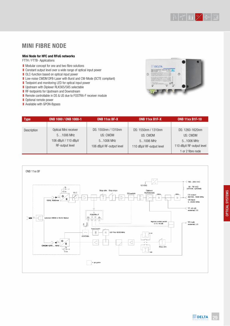
ONB 11xx BF
MINI FIBRE NODE
Mini Node for HFC and RFoG networks
FTTH / FTTB- Applications
ll Modular concept for one and two fibre solutions
ll Constant output level over a wide range of optical input power
ll OLC-function based on optical input power
ll Low-noise CWDM DFB-Laser with Burst and CW-Mode (SCTE compliant)
ll Testpoint and monitoring LED for optical input power
ll Upstream with Diplexer RLK565/585 selectable
ll RF-testpoints for Upstream and Downstream
ll Remote controllable in DS & US due to FOSTRA-F receiver module
ll Optional remote power
ll Available with GPON-Bypass
Description Optical Mini receiver
5…1006 MHz
106 dBµV / 110 dBµV
RF-output level
DS: 1550nm / 1310nm
US: CWDM
5...1006 MHz
106 dBµV RF-output level
DS: 1260-1620nm
US: CWDM
5...1006 MHz
110 dBµV RF-output level
1 or 2 fibre node
DS: 1550nm / 1310nm
US: CWDM
5...1006 MHz
110 dBµV RF-output level
Type ONB 1000 / ONB 1000-1 ONB 11xx BF-X ONB 11xx B1F-X ONB 11xx B1F-10

30
Ups
trea
mD
owns
trea
mM
onito
ring
Type
Applications
Compact die-cast housing
Weight kg
Fiber connectors
RF connectors
Mains feeding V~/W
Operating temperature °C
Adjustment elements
Internal WDM (Tx / Rx) nm
Optical wavelength nm
Optical input power dBm
Frequency range MHz
Frequency response dB
Optical level control (OLC) dBm
RF output level dBµV
C/N
RF level attenuator dB
RF slope dB
Test point RF output dB
Monitoring optical input dBm
Test point optical input V/mW
DFB Laser / optical power dBm
Laser operation
RF input dynamic range dBµV
Frequency range MHz
RF input level dBµV
RF input level attenuator dB
HEC Controller
FOSTRA F Control module
ONB 11xx B
HFC, FTTC, DOCSIS-PON/RfoG
210 x 123 x 70 / IP 50, In-door
1.3
SC/APC, 2 pcs (without internal WDM), 1 pcs (with internal WDM)
F-Buchse
185…265 / 13.5
-20…+55 Free convection
Step Spin Regler 2 dB steps for level and slope control
DS / US
1550 / 1310 (others on request)
-8…+2
-7…+1 (RF-output level ± 1 dB)
47/85…1006 (Diplexer RLK 30 / 65)
± 0.7
106 @ -7...+1 dBm, OMI = 4% (CTB,CSO > 60 dBc, 41Ch. PAL, 54 Ch.QAM, Flat)
110 @ -7...+1 dBm, OMI = 4% (CTB,CSO > 60 dBc, 41Ch. PAL, 54 Ch.QAM, Slope 5dB)
53 @ -3 dBm, OMI 4%
0 / 2 / 4 6 / 8 / 10 Step Spin Controller
0 / 2 / 4 6 / 8 / 10 Step Spin Controller
Green LED on: input > -10
2 (Inside enclosure)
+3
Burst Mode, Laser „Delay-Time“ < 1 µSec
74 … 100 („Laser ON“ @ 70 dBµV)
15...65/85 as well as 15...85/105
OMI 15% @ 72 (Att. = 0 dB)
0 / 2 / 4 6 / 8 / 10 Step Spin, 0/10/20dB Jumper Attn.
Green LED on: output power available
FSK-TX, 868 MHz
FSK Receiver RX : 868 MHz

OP
TIC
AL S
YS
TE
MS
31
Please use the follwoing article numbers when ordering:
VERSIONS
Optical receiver, 106 dBμV, 5-1006 MHz
Optical receiver, 110 dBμV, 5-1006 MHz
ONB with 1270 nm in US, 1310 in DS, integrated WDM
ONB with 1290 nm in US, 1310 in DS, integrated WDM
ONB with 1330 nm in US, 1310 in DS, integrated WDM
ONB with 1350 nm in US, 1310 in DS, integrated WDM
ONB with 1370 nm in US, 1310 in DS, integrated WDM
ONB with 1390 nm in US, 1310 in DS, integrated WDM
ONB with 1410 nm in US, 1310 in DS, integrated WDM
ONB with 1430 nm in US, 1310 in DS, integrated WDM
ONB with 1450 nm in US, 1310 in DS, integrated WDM
ONB with 1470 nm in US, 1310 in DS, integrated WDM
ONB with 1490 nm in US, 1310 in DS, integrated WDM
ONB with 1510 nm in US, 1310 in DS, integrated WDM
ONB with 1530 nm in US, 1310 in DS, integrated WDM
ONB with 1550 nm in US, 1310 in DS, integrated WDM
ONB with 1570 nm in US, 1310 in DS, integrated WDM
ONB with 1590 nm in US, 1310 in DS, integrated WDM
ONB with 1610 nm in US, 1310 in DS, integrated WDM
ONB with 1270 nm in US, 1550 in DS, integrated WDM
ONB with 1290 nm in US, 1550 in DS, integrated WDM
ONB with 1310 nm in US, 1550 in DS, integrated WDM
ONB 1000
ONB 1000-1
ONB 1127 BF-13-1
ONB 1129 BF-13-1
ONB 1133 BF-13-1
ONB 1135 BF-13-1
ONB 1137 BF-13-1
ONB 1139 BF-13-1
ONB 1141 BF-13-1
ONB 1143 BF-13-1
ONB 1145 BF-13-1
ONB 1147 BF-13-1
ONB 1149 BF-13-1
ONB 1151 BF-13-1
ONB 1153 BF-13-1
ONB 1155 BF-13-1
ONB 1157 BF-13-1
ONB 1159 BF-13-1
ONB 1161 BF-13-1
ONB 1127 BF-15-1
ONB 1129 BF-15-1
ONB 1131 BF-15-1
5700 1958
5700 2528
5700 2179
5700 2180
5700 2181
5700 2182
5700 2183
5700 2184
5700 2185
5700 2186
5700 2187
5700 2188
5700 2189
5700 2190
5700 2191
5700 2192
5700 2193
5700 2194
5700 2195
5700 2274
5700 2275
5700 1963
Type Article-No. Remarks
ONB R 11 xx BF-xx-x-xx
11: up to 1006 MHz
12: up to 1218 MHz
B: burst mode and
continuous mode
F: FSK-monitoring
-: RF-output level 106 dBμV
1: RF-output level 110 dBμV
13: 1310 nm
15: 1550 nm
10: 1260-1620
nm
27: 1270 nm
29: 1290 nm
31: 1310 nm
33: 1330 nm
35: 1350 nm
37: 1370 nm
39: 1390 nm
41: 1410 nm
43: 1430 nm
45: 1450 nm
47: 1470 nm
49: 1490 nm
51: 1510 nm
53: 1530 nm
55: 1550 nm
57: 1570 nm
59: 1590 nm
61: 1610 nm
Diplexer (MHz)Powering (V~) Frequency
range (MHz)
US-wave-
length
Laser operation,
monitoring
DS-wave-
length
Number of Fibres
1: one iber for US
and DS
2: one iber for US
and one iber for
DS
GPON: one iber for
RFoG and
GPON bypass
ilter
-: local powering
230 V~
R: remote powering
28-65 V~
-: RLK 565
(5-65/85)
85: RLK 585
(5-85/105)
204: RLK 5204
(5-204/ 258)

32
Type
ONB with 1330 nm in US, 1550 in DS, integrated WDM
ONB with 1350 nm in US, 1550 in DS, integrated WDM
ONB with 1370 nm in US, 1550 in DS, integrated WDM, RF-outp. 106 dBµV
ONB with 1390 nm in US, 1550 in DS, integrated WDM, RF-outp. 106 dBµV
ONB with 1410 nm in US, 1550 in DS, integrated WDM, RF-outp. 106 dBµV
ONB with 1430 nm in US, 1550 in DS, integrated WDM, RF-outp. 106 dBµV
ONB with 1450 nm in US, 1550 in DS, integrated WDM, RF-outp. 106 dBµV
ONB with 1470 nm in US, 1550 in DS, integrated WDM, RF-outp. 106 dBµV
ONB with 1490 nm in US, 1550 in DS, integrated WDM, RF-outp. 106 dBµV
ONB with 1510 nm in US, 1550 in DS, integrated WDM, RF-outp. 106 dBµV
ONB with 1530 nm in US, 1550 in DS, integrated WDM, RF-outp. 106 dBµV
ONB with 1570 nm in US, 1550 in DS, integrated WDM, RF-outp. 106 dBµV
ONB with 1590 nm in US, 1550 in DS, integrated WDM, RF-outp. 106 dBµV
ONB with 1610 nm in US, 1550 in DS, integrated WDM, RF-outp. 106 dBµV
ONB with 1270 nm in US, 1550 in DS, integrated WDM, RF-outp. 110 dBµV
ONB with 1290 nm in US, 1550 in DS, integrated WDM, RF-outp. 110 dBµV
ONB with 1310 nm in US, 1550 in DS, integrated WDM, RF-outp. 110 dBµV
ONB with 1330 nm in US, 1550 in DS, integrated WDM, RF-outp. 110 dBµV
ONB with 1350 nm in US, 1550 in DS, integrated WDM, RF-outp. 110 dBµV
ONB with 1370 nm in US, 1550 in DS, integrated WDM, RF-outp. 110 dBµV
ONB with 1390 nm in US, 1550 in DS, integrated WDM, RF-outp. 110 dBµV
ONB with 1410 nm in US, 1550 in DS, integrated WDM, RF-outp. 110 dBµV
ONB with 1430 nm in US, 1550 in DS, integrated WDM, RF-outp. 110 dBµV
ONB with 1450 nm in US, 1550 in DS, integrated WDM, RF-outp. 110 dBµV
ONB with 1470 nm in US, 1550 in DS, integrated WDM, RF-outp. 110 dBµV
ONB with 1490 nm in US, 1550 in DS, integrated WDM, RF-outp. 110 dBµV
ONB with 1510 nm in US, 1550 in DS, integrated WDM, RF-outp. 110 dBµV
ONB with 1530 nm in US, 1550 in DS, integrated WDM, RF-outp. 110 dBµV
ONB with 1570 nm in US, 1550 in DS, integrated WDM, RF-outp. 110 dBµV
ONB with 1590 nm in US, 1550 in DS, integrated WDM, RF-outp. 110 dBµV
ONB with 1610 nm in US, 1550 in DS, integrated WDM, RF-outp. 110 dBµV
ONB with 1270 nm in US, 1260/1620 in DS, integrated WDM, 2 iber, RLK 85
ONB with 1290 nm in US, 1260/1620 in DS, integrated WDM, 2 iber, RLK 85
ONB with 1310 nm in US, 1260/1620 in DS, integrated WDM, 2 iber, RLK 85
ONB with 1330 nm in US, 1260/1620 in DS, integrated WDM, 2 iber, RLK 85
ONB with 1350 nm in US, 1260/1620 in DS, integrated WDM, 2 iber, RLK 85
ONB with 1370 nm in US, 1260/1620 in DS, integrated WDM, 2 iber, RLK 85
ONB with 1390 nm in US, 1260/1620 in DS, integrated WDM, 2 iber, RLK 85
ONB with 1410 nm in US, 1260/1620 in DS, integrated WDM, 2 iber, RLK 85
ONB with 1430 nm in US, 1260/1620 in DS, integrated WDM, 2 iber, RLK 85
ONB with 1450 nm in US, 1260/1620 in DS, integrated WDM, 2 iber, RLK 85
ONB with 1470 nm in US, 1260/1620 in DS, integrated WDM, 2 iber, RLK 85
ONB with 1490 nm in US, 1260/1620 in DS, integrated WDM, 2 iber, RLK 85
ONB with 1510 nm in US, 1260/1620 in DS, integrated WDM, 2 iber, RLK 85
ONB with 1530 nm in US, 1260/1620 in DS, integrated WDM, 2 iber, RLK 85
ONB with 1550 nm in US, 1260/1620 in DS, integrated WDM, 2 iber, RLK 85
ONB with 1570 nm in US, 1260/1620 in DS, integrated WDM, 2 iber, RLK 85
ONB with 1590 nm in US, 1260/1620 in DS, integrated WDM, 2 iber, RLK 85
ONB with 1610 nm in US, 1260/1620 in DS, integrated WDM, 2 iber, RLK 85
ONB with 1270 nm in US, 1260/1620 in DS, integrated WDM, 2 iber, RLK 85
ONB with 1290 nm in US, 1260/1620 in DS, integrated WDM, 2 iber, RLK 85
ONB 1133 BF-15-1
ONB 1135 BF-15-1
ONB 1137 BF-15-1
ONB 1139 BF-15-1
ONB 1141 BF-15-1
ONB 1143 BF-15-1
ONB 1145 BF-15-1
ONB 1147 BF-15-1
ONB 1149 BF-15-1
ONB 1151 BF-15-1
ONB 1153 BF-15-1
ONB 1157 BF-15-1
ONB 1159 BF-15-1
ONB 1161 BF-15-1
ONB 1127 B1F-15-1
ONB 1129 B1F-15-1
ONB 1131 B1F-15-1
ONB 1133 B1F-15-1
ONB 1135 B1F-15-1
ONB 1137 B1F-15-1
ONB 1139 B1F-15-1
ONB 1141 B1F-15-1
ONB 1143 B1F-15-1
ONB 1145 B1F-15-1
ONB 1147 B1F-15-1
ONB 1149 B1F-15-1
ONB 1151 B1F-15-1
ONB 1153 B1F-15-1
ONB 1157 B1F-15-1
ONB 1159 B1F-15-1
ONB 1161 B1F-15-1
ONB 1127 B1F-10-2-85
ONB 1129 B1F-10-2-85
ONB 1131 B1F-10-2-85
ONB 1133 B1F-10-2-85
ONB 1135 B1F-10-2-85
ONB 1137 B1F-10-2-85
ONB 1139 B1F-10-2-85
ONB 1141 B1F-10-2-85
ONB 1143 B1F-10-2-85
ONB 1145 B1F-10-2-85
ONB 1147 B1F-10-2-85
ONB 1149 B1F-10-2-85
ONB 1151 B1F-10-2-85
ONB 1153 B1F-10-2-85
ONB 1155 B1F-10-2-85
ONB 1157 B1F-10-2-85
ONB 1159 B1F-10-2-85
ONB 1161 B1F-10-2-85
ONBR 1127 B1F-10-2-85
ONBR 1129 B1F-10-2-85
5700 2276
5700 2277
5700 2278
5700 2279
5700 2280
5700 2281
5700 2282
5700 2283
5700 2284
5700 2285
5700 2286
5700 2287
5700 2288
5700 1962
5700 2495
5700 2496
5700 2497
5700 2498
5700 2499
5700 2500
5700 2501
5700 2502
5700 2503
5700 2504
5700 2505
5700 2506
5700 2507
5700 2508
5700 2509
5700 2510
5700 2433
5700 2713
5700 2712
5700 2711
5700 2710
5700 2709
5700 2708
5700 2707
5700 2706
5700 2705
5700 2704
5700 2699
5700 2698
5700 2697
5700 2696
5700 2695
5700 2694
5700 2693
5700 2690
5700 2773
5700 2772
Article-No. Remarks

OP
TIC
AL S
YS
TE
MS
33
ONB with 1310 nm in US, 1260/1620 in DS, integrated WDM, 2 iber, RLK 85
ONB with 1330 nm in US, 1260/1620 in DS, integrated WDM, 2 iber, RLK 85
ONB with 1350 nm in US, 1260/1620 in DS, integrated WDM, 2 iber, RLK 85
ONB with 1370 nm in US, 1260/1620 in DS, integrated WDM, 2 iber, RLK 85
ONB with 1390 nm in US, 1260/1620 in DS, integrated WDM, 2 iber, RLK 85
ONB with 1410 nm in US, 1260/1620 in DS, integrated WDM, 2 iber, RLK 85
ONB with 1430 nm in US, 1260/1620 in DS, integrated WDM, 2 iber, RLK 85
ONB with 1450 nm in US, 1260/1620 in DS, integrated WDM, 2 iber, RLK 85
ONB with 1470 nm in US, 1260/1620 in DS, integrated WDM, 2 iber, RLK 85
ONB with 1490 nm in US, 1260/1620 in DS, integrated WDM, 2 iber, RLK 85
ONB with 1510 nm in US, 1260/1620 in DS, integrated WDM, 2 iber, RLK 85
ONB with 1530 nm in US, 1260/1620 in DS, integrated WDM, 2 iber, RLK 85
ONB with 1550 nm in US, 1260/1620 in DS, integrated WDM, 2 iber, RLK 85
ONB with 1570 nm in US, 1260/1620 in DS, integrated WDM, 2 iber, RLK 85
ONB with 1590 nm in US, 1260/1620 in DS, integrated WDM, 2 iber, RLK 85
ONB with 1610 nm in US, 1260/1620 in DS, integrated WDM, 2 iber, RLK 85
ONB with 1270 nm in US, 1260/1620 in DS, integrated WDM, 1 iber, RLK 85
ONB with 1290 nm in US, 1260/1620 in DS, integrated WDM, 1 iber, RLK 85
ONB with 1310 nm in US, 1260/1620 in DS, integrated WDM, 1 iber, RLK 85
ONB with 1330 nm in US, 1260/1620 in DS, integrated WDM, 1 iber, RLK 85
ONB with 1350 nm in US, 1260/1620 in DS, integrated WDM, 1 iber, RLK 85
ONB with 1370 nm in US, 1260/1620 in DS, integrated WDM, 1 iber, RLK 85
ONB with 1390 nm in US, 1260/1620 in DS, integrated WDM, 1 iber, RLK 85
ONB with 1410 nm in US, 1260/1620 in DS, integrated WDM, 1 iber, RLK 85
ONB with 1430 nm in US, 1260/1620 in DS, integrated WDM, 1 iber, RLK 85
ONB with 1450 nm in US, 1260/1620 in DS, integrated WDM, 1 iber, RLK 85
ONB with 1470 nm in US, 1260/1620 in DS, integrated WDM, 1 iber, RLK 85
ONB with 1490 nm in US, 1260/1620 in DS, integrated WDM, 1 iber, RLK 85
ONB with 1510 nm in US, 1260/1620 in DS, integrated WDM, 1 iber, RLK 85
ONB with 1530 nm in US, 1260/1620 in DS, integrated WDM, 1 iber, RLK 85
ONB with 1550 nm in US, 1260/1620 in DS, integrated WDM, 1 iber, RLK 85
ONB with 1570 nm in US, 1260/1620 in DS, integrated WDM, 1 iber, RLK 85
ONB with 1590 nm in US, 1260/1620 in DS, integrated WDM, 1 iber, RLK 85
ONB with 1610 nm in US, 1260/1620 in DS, integrated WDM, 1 iber, RLK 85
ONB with 1550 nm in DS, integrated GPON Bypass-ilter
ONB with 1610 nm in US, 1550 in DS, integrated GPON Bypass-ilter
ONBR 1131 B1F-10-2-85
ONBR 1133 B1F-10-2-85
ONBR 1135 B1F-10-2-85
ONBR 1137 B1F-10-2-85
ONBR 1139 B1F-10-2-85
ONBR 1141 B1F-10-2-85
ONBR 1143 B1F-10-2-85
ONBR 1145 B1F-10-2-85
ONBR 1147 B1F-10-2-85
ONBR 1149 B1F-10-2-85
ONBR 1151 B1F-10-2-85
ONBR 1153 B1F-10-2-85
ONBR 1155 B1F-10-2-85
ONBR 1157 B1F-10-2-85
ONBR 1159 B1F-10-2-85
ONBR 1161 B1F-10-2-85
ONB 1127 B1F-10-1-85
ONB 1129 B1F-10-1-85
ONB 1131 B1F-10-1-85
ONB 1133 B1F-10-1-85
ONB 1135 B1F-10-1-85
ONB 1137 B1F-10-1-85
ONB 1139 B1F-10-1-85
ONB 1141 B1F-10-1-85
ONB 1143 B1F-10-1-85
ONB 1145 B1F-10-1-85
ONB 1147 B1F-10-1-85
ONB 1149 B1F-10-1-85
ONB 1151 B1F-10-1-85
ONB 1153 B1F-10-1-85
ONB 1155 B1F-10-1-85
ONB 1157 B1F-10-1-85
ONB 1159 B1F-10-1-85
ONB 1161 B1F-10-1-85
ONB 1000 - 1 - GPON
ONB 1161 B1F- GPON
5700 2771
5700 2770
5700 2769
5700 2768
5700 2767
5700 2766
5700 2765
5700 2764
5700 2572
5700 2573
5700 2574
5700 2575
5700 2576
5700 2577
5700 2578
5700 2579
5700 2783
5700 2784
5700 2785
5700 2786
5700 2787
5700 2788
5700 2789
5700 2790
5700 2791
5700 2792
5700 2793
5700 2794
5700 2795
5700 2796
5700 2797
5700 2798
5700 2799
5700 2800
5700 2634
5700 2594
Type Article-No. Remarks
34
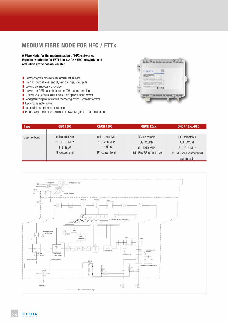
Beschreibung
optical receiver
5…1218 MHz
115 dBµV
RF-output level
optical receiver
5...1218 MHz
115 dBµV
RF-output level
DS: selectable
US: CWDM
5...1218 MHz
115 dBµV RF-output level
controllable
DS: selectable
US: CWDM
5...1218 MHz
115 dBµV RF-output level
Type ONC 1200 ONCR 1200 ONCR 12xx ONCR 12xx-BFD
MEDIUM FIBRE NODE FOR HFC / FTTx
A Fibre Node for the modernisation of HFC-networks
Especially suitable for FFTLA in 1.2 GHz HFC-networks and
reduction of the coaxial cluster
ll Compact optical receiver with modular return way
ll High RF output level and dynamic range, 2 outputs
ll Low noise impedance receiver
ll Low noise DFB- laser in burst or CW mode operation
ll Optical level control (OLC) based on optical input power
ll 7-Segment display for various monitoring options and easy control
ll Optional remote power
ll Internal fibre splice management
ll Return way transmitter available in CWDM-grid (1270 - 1610nm)

OP
TIC
AL S
YS
TE
MS
35
Ups
trea
mD
owns
trea
m
Type
Applications
Compact die-cast housing mm
Fibre connectors (internal)
Connectors
Mains feeding V~/W
Remote feeding V~
Operating temperature °C
OLC dBm
Adjustment elements dB
Return laser module
RF outputs
Optical wavelength nm
Optical input power dBm
Optical return loss dB
Frequency range MHz
Frequency response dB
RF output power dBµV
C/N dBc
RF slope dB
RF level adjustment dB
RF test point dB
Monitoring optical input dBm
Optical input power
Laser wavelength nm
Optical Power dBm
Optical return loss dB
Frequency range MHz
RF input level (CWDM) dBµV
RF input level attenuator dB
RF test point dB
Monitoring optical output
ONC(R) 1200, ONCR 12xx, ONCR 12xx-BFD
HFC, FTTC/FTTB
225 x 195 x 95 / IP 65, out-door
SC/APC (internal fibre slice management)
PG 11-RF output , PG 13.5 (opt. fibre feed-through)
185…265 / 20
28…65 / 0.67 A @ 30 VAC, 10 A
-20…+55
-7…+1 (RF ouput ±1dB, AGC)
0…15 (electronically adjustable in 1dB steps, 7-segm.display+micro)
various available (3,6dBm DFB)
1 od. 2 (with 2-way splitter or tab module 10 od. 20 dB)
1260 …1620
-8…+2
≥ 20 -1.75/Okt. (65 - 1218 MHz)
≥ 20 -2/Okt. (85 - 1218 MHz)
≥ 20 -3/Okt. (204-1218 MHz)
min 12 @ 1218 MHz
85...1218 MHz
± 0.7 max. ±1
115 CENELEC, flat, CTB/CSO >60dB
50 @ -3 dBm, OMI 4%
0…15 dB (electronically adjustable in 1dB steps)
0…15 dB (electronically adjustable in 1dB steps)
20 (internal)
greenLED on: input > -10
7-segment display, power meter function
1270 - 1610
3;6
60
5…65/85/204 (Diplexer RLK 65 / 85 / 204)
65, OMI 7% @ 0 dB attn
0…15 (electronically adjustable in 1 dB steps)
-20 (internal)
Green LED on: output power available
36
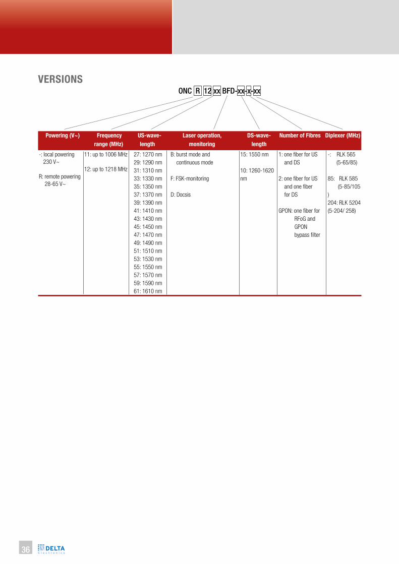
VERSIONSONC R 12 xx BFD-xx-x-xx
11: up to 1006 MHz
12: up to 1218 MHz
B: burst mode and
continuous mode
F: FSK-monitoring
D: Docsis
15: 1550 nm
10: 1260-1620
nm
27: 1270 nm
29: 1290 nm
31: 1310 nm
33: 1330 nm
35: 1350 nm
37: 1370 nm
39: 1390 nm
41: 1410 nm
43: 1430 nm
45: 1450 nm
47: 1470 nm
49: 1490 nm
51: 1510 nm
53: 1530 nm
55: 1550 nm
57: 1570 nm
59: 1590 nm
61: 1610 nm
Diplexer (MHz)Powering (V~) Frequency
range (MHz)
US-wave-
length
Laser operation,
monitoring
DS-wave-
length
Number of Fibres
1: one iber for US
and DS
2: one iber for US
and one iber
for DS
GPON: one iber for
RFoG and
GPON
bypass ilter
-: local powering
230 V~
R: remote powering
28-65 V~
-: RLK 565
(5-65/85)
85: RLK 585
(5-85/105
)
204: RLK 5204
(5-204/ 258)
OP
TIC
AL S
YS
TE
MS
37
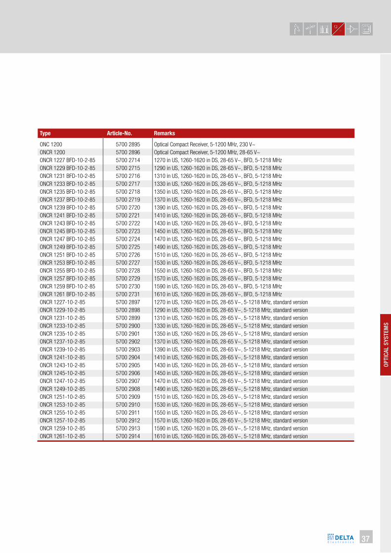
Type
Optical Compact Receiver, 5-1200 MHz, 230 V~
Optical Compact Receiver, 5-1200 MHz, 28-65 V~
1270 in US, 1260-1620 in DS, 28-65 V~, BFD, 5-1218 MHz
1290 in US, 1260-1620 in DS, 28-65 V~, BFD, 5-1218 MHz
1310 in US, 1260-1620 in DS, 28-65 V~, BFD, 5-1218 MHz
1330 in US, 1260-1620 in DS, 28-65 V~, BFD, 5-1218 MHz
1350 in US, 1260-1620 in DS, 28-65 V~, BFD, 5-1218 MHz
1370 in US, 1260-1620 in DS, 28-65 V~, BFD, 5-1218 MHz
1390 in US, 1260-1620 in DS, 28-65 V~, BFD, 5-1218 MHz
1410 in US, 1260-1620 in DS, 28-65 V~, BFD, 5-1218 MHz
1430 in US, 1260-1620 in DS, 28-65 V~, BFD, 5-1218 MHz
1450 in US, 1260-1620 in DS, 28-65 V~, BFD, 5-1218 MHz
1470 in US, 1260-1620 in DS, 28-65 V~, BFD, 5-1218 MHz
1490 in US, 1260-1620 in DS, 28-65 V~, BFD, 5-1218 MHz
1510 in US, 1260-1620 in DS, 28-65 V~, BFD, 5-1218 MHz
1530 in US, 1260-1620 in DS, 28-65 V~, BFD, 5-1218 MHz
1550 in US, 1260-1620 in DS, 28-65 V~, BFD, 5-1218 MHz
1570 in US, 1260-1620 in DS, 28-65 V~, BFD, 5-1218 MHz
1590 in US, 1260-1620 in DS, 28-65 V~, BFD, 5-1218 MHz
1610 in US, 1260-1620 in DS, 28-65 V~, BFD, 5-1218 MHz
1270 in US, 1260-1620 in DS, 28-65 V~, 5-1218 MHz, standard version
1290 in US, 1260-1620 in DS, 28-65 V~, 5-1218 MHz, standard version
1310 in US, 1260-1620 in DS, 28-65 V~, 5-1218 MHz, standard version
1330 in US, 1260-1620 in DS, 28-65 V~, 5-1218 MHz, standard version
1350 in US, 1260-1620 in DS, 28-65 V~, 5-1218 MHz, standard version
1370 in US, 1260-1620 in DS, 28-65 V~, 5-1218 MHz, standard version
1390 in US, 1260-1620 in DS, 28-65 V~, 5-1218 MHz, standard version
1410 in US, 1260-1620 in DS, 28-65 V~, 5-1218 MHz, standard version
1430 in US, 1260-1620 in DS, 28-65 V~, 5-1218 MHz, standard version
1450 in US, 1260-1620 in DS, 28-65 V~, 5-1218 MHz, standard version
1470 in US, 1260-1620 in DS, 28-65 V~, 5-1218 MHz, standard version
1490 in US, 1260-1620 in DS, 28-65 V~, 5-1218 MHz, standard version
1510 in US, 1260-1620 in DS, 28-65 V~, 5-1218 MHz, standard version
1530 in US, 1260-1620 in DS, 28-65 V~, 5-1218 MHz, standard version
1550 in US, 1260-1620 in DS, 28-65 V~, 5-1218 MHz, standard version
1570 in US, 1260-1620 in DS, 28-65 V~, 5-1218 MHz, standard version
1590 in US, 1260-1620 in DS, 28-65 V~, 5-1218 MHz, standard version
1610 in US, 1260-1620 in DS, 28-65 V~, 5-1218 MHz, standard version
5700 2895
5700 2896
5700 2714
5700 2715
5700 2716
5700 2717
5700 2718
5700 2719
5700 2720
5700 2721
5700 2722
5700 2723
5700 2724
5700 2725
5700 2726
5700 2727
5700 2728
5700 2729
5700 2730
5700 2731
5700 2897
5700 2898
5700 2899
5700 2900
5700 2901
5700 2902
5700 2903
5700 2904
5700 2905
5700 2906
5700 2907
5700 2908
5700 2909
5700 2910
5700 2911
5700 2912
5700 2913
5700 2914
ONC 1200
ONCR 1200
ONCR 1227 BFD-10-2-85
ONCR 1229 BFD-10-2-85
ONCR 1231 BFD-10-2-85
ONCR 1233 BFD-10-2-85
ONCR 1235 BFD-10-2-85
ONCR 1237 BFD-10-2-85
ONCR 1239 BFD-10-2-85
ONCR 1241 BFD-10-2-85
ONCR 1243 BFD-10-2-85
ONCR 1245 BFD-10-2-85
ONCR 1247 BFD-10-2-85
ONCR 1249 BFD-10-2-85
ONCR 1251 BFD-10-2-85
ONCR 1253 BFD-10-2-85
ONCR 1255 BFD-10-2-85
ONCR 1257 BFD-10-2-85
ONCR 1259 BFD-10-2-85
ONCR 1261 BFD-10-2-85
ONCR 1227-10-2-85
ONCR 1229-10-2-85
ONCR 1231-10-2-85
ONCR 1233-10-2-85
ONCR 1235-10-2-85
ONCR 1237-10-2-85
ONCR 1239-10-2-85
ONCR 1241-10-2-85
ONCR 1243-10-2-85
ONCR 1245-10-2-85
ONCR 1247-10-2-85
ONCR 1249-10-2-85
ONCR 1251-10-2-85
ONCR 1253-10-2-85
ONCR 1255-10-2-85
ONCR 1257-10-2-85
ONCR 1259-10-2-85
ONCR 1261-10-2-85
Article-No. Remarks

38
SEGMENTABLE FIBRE NODE 2X2 FOR HFC
ONS 9238 is one of the most advanced optical nodes dedicated to tra-
ditional HFC and FTTB networks. Besides its compact size the node is
distinguished by a high output level and a low power consumption.The
ONS can be adjusted uninterruptedly and is remote controllable with
FOSTRA control modules. The main advantages of the device include
the following modes:
• „AUTOALIGNMENT“, depending on the given input parameters of optical signal and the parameters of RF output signal, it enables
automatic internal control, which ensures that the programmed pa-
rameters are obtained.
The ONS can be equipped with monitoring module including RJ45 or
SFP interface.
Depending on the need, there is a possibility of remote monitoring
using fibre optic or copper medium. Total independence from DOCSIS
infrastructure and RF parameter measurement system allows the ope-
rator to consciously control and change the quality of received signals.
ONS 9238 can cooperate with an optical switch, forming an inde-
pendent monitoring infrastructure or optional with DOCSIS or HMS
monitoring system.
ll 1 GHz frequency range
ll Designed to work in HFC, FTTLA, FTTLN, FTTB or FTTC networks
ll Easy configuration, electronic adjustment and universal plug-in modules
ll Built-in AGC (Automatic Gain Control)
ll 3-DIGIT LED display
ll 2x2 full redundancy and segmentation in forward and reverse
ll Local or remote powering
ll Monitoring via SNMP v2c and WWW
Article-No.
Description
Type ONS 9238
5700 1938
Segm. Fibre Node 2x2
5700 1939
Rem. Segm. Fibre Node 2x2
ONS 9238 R
5700 2087
Segm. Fibre Node 2x2
ONS 9238/FOSTRA D ONS 9238 R/FOSTRA D
5700 2088
Rem. Segm. Fibre Node 2x2

OP
TIC
AL S
YS
TE
MS
39
Ups
trea
m T
XD
owns
trea
m R
X
Type
Applications
Compact die-cast housing mm
Fibre connectors (internal)
Connectors
Mains feeding V~/W
Remote feeding V~
Operating temperature °C
Testpoint A1, A2 dB
Return laser module
RF outputs
Optical wavelength nm
Optical input power dBm
OLC
Optical return loss dB
Frequency range MHz
Frequency response dB
Output level 1310nm @ -3 dBm
E1 and E2 = 6 dB slope, 3,5% OMI
E1 and E2 = 6 dB slope, 4,0% OMI
C/N dBc
Interstage Att. A1, A2 dB
Interstage slope E1, E2 dB
RF test point dB
Laser / optical power
(e.g. OTS 1610 D, 1610 nm DFB + 3 dBm)
Frequency range MHz
RF input level (CWDM) dBµV
RF level attenuator A3, 4 dB
RF test point dB
Monitoring optical output
ONS 9238
HFC, FTTC/FTTB
245 x 207 x 125 / IP 65, Out-door
SC/APC
PG 11 or 5/8“ RF out, PG 13,5 (Optical fibre cable input)
185…265 / < 35 (ONS 9238)
28…70 / 0,67 A @ 30 VAC, 10 A (ONS 9238 R, 57001939)
-20…+55, Free convection
-20 (internal)
various available (DFB, FP, CWDM)
2 x 2 (redundant)
1100 …1650 (ORS 98 module)
-7…+2 (1310nm)
Yes (-6 … +0 dBm, optical level control)
> 45
85…1006 (Diplex filter RLK 465)
± 0.75
2 x 114 dBµV (acc. CENELEC 42 CTB/CSO > 60 dBc)
2 x 116 dBµV (acc. CENELEC 42 CTB/CSO > 58 dBc)
52 @ -3 dBm, OMI 4%
0…15 dB (adjustable by electronic step attenuators in 0,5 dB steps)
0…15 dB (adjustable by electronic step attenuators in 0,5 dB steps)
-20 (internal)
1310/1610 nm: FP or DFB-Laser / 0 or 3 dBm
CWDM 1470…1610 nm: DFB-Laser / 3 dBm
5…65 (other on request)
OMI 10 % @ 70, 0 dB attn
0…20 (1 dB step attn.)
-20 (internal)
Green LED on: output power available
Modules for ONS 9238
ORS 98
OTS 1310 D
OTS 1610 D
OTS 1xxx CWDM
RLK 465 (2x)
NHP 915
VM 902
AM 9-01-10
FOSTRA D
JUM-ONS
Type DescriptionArticle-No.
RX-Module 1260 -1620nm, -7…2 dBm
TX-Module, DFB 1310nm, +3 dBm
TX-Module, DFB 1610nm, +3 dBm
TX-Module, CWDM 1xxxnm, +3 dBm
Diplexer 5 - 65/85-1000 MHz
Rev path filter FPA 15 - 65 MHz
Output splitter VM 2-fach 3.5 dB
Output RF Tap AM 10 dB
DOCSIS Transponder
0 dB Jumper for output 2
5700 1940
5700 1941
5700 1942
on request
5700 1945
5700 1946
5700 1947
5700 1948
on request
5700 1984

40
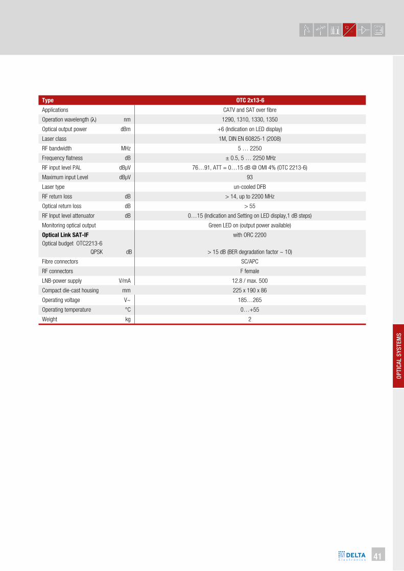
OPTICAL CATV / SAT-IF TRANSMITTER
Optical compact transmitter for RF and IF signals over fibre
ll Compact optical transmitter with 2 or 4 pluggable modules
ll Compatible with the compact receiver ORC 2400 with up to 4 re-
ceiver modules
ll Bandwidth 47...2250 MHz
ll Ready for analogue PAL TV channels, SAT QPSK distribution
ll High linearity, DFB Laser with internal optical isolator
ll Low distortion wavelengths: 1270, 1310, 1330, 1350 nm
ll Up to 30 km fibre length
OTC 2213-6
Article-No.
Description
Type OTC 2113-6 OTC 2213-6 OTC 2413-6
5700 1532
Optical compact
transmitter, single version with 1
transmitter module
6 dBm
5700 1534
Optical compact
transmitter, twin version with 2
transmitter modules
6 dBm
5700 2925
Optical compact
transmitter, quattro version with 4
transmitter modules
6 dBm
OP
TIC
AL S
YS
TE
MS
41
Applications
Operation wavelength (λ) nm
Optical output power dBm
Laser class
RF bandwidth MHz
Frequency flatness dB
RF input level PAL dBµV
Maximum input Level dBµV
Laser type
RF return loss dB
Optical return loss dB
RF Input level attenuator dB
Monitoring optical output
Optical Link SAT-IF
Optical budget OTC2213-6
QPSK dB
Fibre connectors
RF connectors
LNB-power supply V/mA
Compact die-cast housing mm
Operating voltage V~
Operating temperature °C
Weight kg
Type OTC 2x13-6
CATV and SAT over fibre
1290, 1310, 1330, 1350
+6 (Indication on LED display)
1M, DIN EN 60825-1 (2008)
5 … 2250
± 0.5, 5 … 2250 MHz
76…91, ATT = 0…15 dB @ OMI 4% (OTC 2213-6)
93
un-cooled DFB
> 14, up to 2200 MHz
> 55
0…15 (Indication and Setting on LED display,1 dB steps)
Green LED on (output power available)
with ORC 2200
> 15 dB (BER degradation factor ~ 10)
SC/APC
F female
12.8 / max. 500
225 x 190 x 86
185…265
0…+55
2

42
ORC 2200
OPTICAL CATV / SAT-IF RECEIVER
Optical compact receiver for RF and IF over fibre
ll Compact optical receiver with 1,2 or 4 pluggable modules
ll Compatible with the compact transmitter OTC 2x13-6
ll Bandwidth 47...2250 MHz
ll Ready for analogue PAL TV channels, SAT QPSK distribution
ll Electronic control of RF output level attenuation for each module
on the LED display
ll Measurement of the optical input power for each module
on the LED display
ll Monitoring LEDs
Article-No.
Description
Type ORC 2100 ORC 2200
5700 1533
Optical compact receiver,
Single version with
1 receiver-module
5 … 2250 MHz
5700 1535
Optical compact receiver,
Dual version with
2 receiver-modules
5 … 2250 MHz
5700 2924
Optical compact receiver,
Quattro version with
4 receiver-modules
5 … 2250 MHz
ORC 2400

OP
TIC
AL S
YS
TE
MS
43
Applications
Operation wavelength (λ) nm
Optical input power dBm
RF bandwidth MHz
Frequency response dB
RF output level dBµV
RF return loss dB
Optical return loss dB
RF output level attenuator dB
Optical input power (digital) dBm
Monitoring optical input
Fibre connectors
RF connectors
Dimensions mm
Power supply V~
Operating temperature °C
Weight kg
Type ORC 2x00
CATV and SAT over fibre
1290 … 1610
-8 … 0 (+2 dBm, absolute Max.)
5 … 2250 (Max. 2400 MHz)
± 0.75 (5 – 2200 MHz, measured with OTC 2213)
89 ± 1 @ 0dBm, OMI = 4% (measured with OTC 2213)
> 14, up to 2200 MHz
> 55
Electronic control, 1 dB steps, 0..15dB (Indication and Setting on LED display)
-8.5 … 0 (Indication on LED display)
Green LED on: input power > -8 dBm
SC/APC
F-female
225 x 190 x 86 / IP 54
185…265
0…+55
2

44
OPTICAL PLC SPLITTER 1260…1620NM
ll Wide operation wavelength 1260…1620nm
ll Good uniformity and low insertion loss
ll Low polarization dependent loss
ll 1 x 2, 1 x 4, 1 x 8, 1 x 16, 1 x 32 and 1 x 64 type splitters
with SC/APC connectors (optional LC/APC) in 19” 1U chassis
Article-No.
Description
Type OCP 1-02 SC OCP 1-04 SC OCP 1-08 SC OCP 1-16 SC OCP 1-32 SC OCP 1-64 SC
5700 1894
Optical PLC Splitter
1200..1620nm,
1 Input, 2 Outputs,
SC/APC, 19“RU
5700 1895
Optical PLC Splitter
1200..1620nm,
1 Input, 4 Outputs,
SC/APC, 19“RU
5700 1896
Optical PLC Splitter
1200..1620nm,
1 Input, 8 Outputs,
SC/APC, 19“RU
5700 1576
Optical PLC Splitter
1200..1620nm,
1 Input, 16 Outputs
SC/APC, 19” 1RU
5700 1577
Optical PLC Splitter
1200..1620nm,
1 Input, 32 Outputs,
SC/APC, 19” 1RU
5700 1900
Optical PLC Splitter
1200..1620nm,
1 Input, 64 Outputs,
SC/APC, 19” 1RU
Operation wavelength (λ) nm
Insertion loss
1 x 2 Splitter dB
1 x 4 Splitter dB
1 x 8 Splitter dB
1 x 16 Splitter dB
1 x 32 Splitter dB
1 x 64 Splitter dB
Polarization dependent loss dB
Uniformity
1 x 2 Splitter dB
1 x 4 Splitter dB
1 x 8 Splitter dB
1 x 16 Splitter dB
1 x 32 Splitter dB
1 x 64 Splitter dB
Return loss dB
Optical fibre connector
Fibre type
Operating temperature °C
Storage temperature °C
Max. input power dBm
Dimensions mm
Type OCP 1-xx SC
1260…1620
3.7
7.2
10.5
13.8
17.2
20.5
< 0.3
< 0.6
< 0.8
< 1.0
< 1.5
< 2
< 2.5
≥ 55
SC/APC
SMF-28e
-40 ~ +85
-40 ~ +85
24.5
482 x 225 x 44 (19” 1RU)

OP
TIC
AL S
YS
TE
MS
45
OPTICAL WAVELENGTH DIVISION MULTIPLEXER
Optical wavelength- division multiplexer multiple optical carrier signals
on a single optical fibre by using different wavelength to carry different
signals.
ll CWDM- channels available
ll Low insertion Loss
ll Wide pass band
ll High channel isolation
ll High Stability and Reliability
ll Compatible with any FTTX PON technology
Operation wavelength (λ) nm
Center Wavelength nm
Channel Spacing nm
Insertion Loss
1 x 2 dB
1 x 3 dB
1 x 4 dB
1 x 8 dB
Channel ripple dB
Isolation dB
Return Loss dB
Max. input power dBm
Operating temperature °C
Storage temperature °C
Dimensions (W x D x H) mm
Type OWDM 1-xx SC
1470 …1610, CWDM- channels (ITU-T G.694.2)
± 0.5
20 (CWDM- Network)
< 0.7
< 1.4
< 1.5
< 3.0
≤ 0.3
≥ 40
≥ 45
24.5
0 ~ +70
-40 ~ +85
482 x 225 x 44
Article-No.
Description
Type OWDM 1-03 SC OWDM 1-02 SC RFoG
5700 1854
Optical Wavelength
Division multiplexer,
developed especially
for GPON solution with
RF Overlay or
GPON + RFoG system, 1550 / 1610
/ 1310
5700 2340
Opt. WDM,
1260-1620 / 1550nm
SC/APC
mini tube
5700 1629
Opt. WDM ,
für RFoG
1550 / 1610nm,
SC/APC, 19” 1HE
OWDM 1-02 SC

46
OPTICAL REPEATER - MULTIPLE INPUTS SINGLE OUTPUTO-MISO
Downstream:
ll Transparent for all DS signals
ll Pluggable XFP-EDFA, 17 dBm
ll GPON/RFoG separation possible
ll Integrated WDM filters and splitter
ll FOSTRA F monitoring
ll Fiber redundancy concept
Upstream:
ll Totally avoiding of OBI
ll Simple optical node with one wavelength
ll CW operating mode (without OBI)
ll OMI transparent, 18 CWDM available
ll Compensation of optical loss caused by splitter
ll Save fibers: several RFoG clusters on one fiber
ll Standard RFoG return path receiver
Type Article-No. Description
O-MISO 1-8
O-MISO 1-16
O-MISO 1-32
5700 2926
5700 2816
5700 2927
Optical Upstream Repeater 8 x Inputs, 1x Output
Optical Upstream Repeater 16 x Inputs, 1x Output
Optical Upstream Repeater 32 x Inputs, 1x Output

OP
TIC
AL S
YS
TE
MS
47
OPTOPAD - OPTICAL MEASURING DEVICE
ll Identification of the signal quality with the OMI App
ll Applicable everywhere where CATV signals are transferred
over fiberglass
ll Simple application without further measuring devices
ll Optical and USB interface available
ll Level adjustment manually or automatically
ll Recommendation of optimal OMI value
ll Portable
ll Article-No. 5700 2337
Technical Data Unit Remarks
Opt. input wavelength (λ) nm 1260-1620
Optical input power dBm Minimal -4 dBm
Maximal 17 dBm
Frequency range MHz 15-1006
Number of HF carriers 100 digital, 100 analogue
OMI measuring range Type 1 1 carrier 13%-50%
100 carriers 1,5%-5%
Type 2 1 carrier 5%-50%
100 carriers 0.1%-5%
Operating temperature °C 0…50
Fibre optic connection SC/APC Patch cords for other connections
Battery life hrs. 2
USB-interface
Fibre optic connection SC/APC
Dimensions mm 116x72x24
Storage temperature °C -20…60
OPTICAL CLEANING KIT
Careful cleaning of fibre optic connectors
ll Easy to clean
ll Up to 50 times cleaning
Article-No.
Description
Type OCT 1 OCT 2
5700 1864
Cleaning tool 1.25 mm, LC/APC
5700 1865
Cleaning tool 2.25 mm, FC/APC, LC/APC

48
OPTICAL FIBRE PATCH CORD
ll Excellent mechanical endurance and low insertion loss
ll Standard exact plastic material, good exchangeability
ll Cable diameter: Ø 3mm
ll Single mode cable type SC, FC, LC, E2000/APC
ll FTTx, Optical fibre CATV and test equipments
Insertion loss dB
Return loss dB
Mode-Operation
Type
Operating temperature °C
Storage temperature °C
Length m
Type OMPC 02 xx-yy
< 0.2
≥ 45
Single Mode, 9 / 125 µm
8 ° APC
-40 - +75
-40 - +85
2
OPTICAL ATTENUATOR
Fibre optical attenuator reduces optical signal
in fixed attenuation values
ll Low insertion loss
ll High stability
ll Connector type attenuator SC, FC/APC
ll Use in optical fibre networks and test equipments
Attenuation value dB
Operation wavelength (λ) nm
Return loss dB
Max. optical input power dBm
Fiber type
Operation temperature °C
Storage temperature °C
Type OATN xx-yy
1.2,…10 ± 0.5 (Others on request)
1200 - 1600
≥ 60 APC
≥ 55 PC
26.5
SC, FC/APC
-30 - +75
-40 - +85
5700 0923
Optical fiber patch
cord, Single mode,
SC - SC/APC,
2 meters
Article-No.
Description
5700 0922
Optical fiber patch
cord, Single mode,
SC - FC/APC,
2 meters
5700 0921
Optical fiber patch
cord, Single mode,
E2000 - SC/APC,
2 meters
5700 0920
Optical fiber patch
cord, Single mode
E2000 - FC/APC,
2 meters
5700 2917
Optical fiber patch
cord, Single mode
LC - SC/APC,
2 meters
5700 2918
Optical fiber patch
cord, Single mode
LC - LC/APC,
2 meters
Article-No.
Description
Type OATN 01 SC OATN 03 SC OATN 06 SC OATN 10 SC
5700 0910
Optical attenuator, -3 dB,
FC/APC
5700 0911
Optical attenuator,
-6 dB, SC/APC
5700 0912
Optical attenuator,
-10 dB, SC/APC
5700 2674
Optical attenuator, -1 dB,
FC/APC
Type OMPC 02 SC-FC OMPC 02 SC-SCOMPC 02 E2-SCOMPC 02 E2-FC OMPC 02 LC-SC OMPC 02 LC-LC

OP
TIC
AL S
YS
TE
MS
49
OPTICAL POWER METER
Fibre optical power meter for accurate measure
of optical signal levels in FTTX deployments
ll Hand held
ll Auto power off
ll Backlight LCD display
ll Self calibration
ll Power measurements in dBm or mw, insertion loss in dB
Measurement range dBm
Operation wavelength (λ) nm
Accuracy/Resolution
Connector
Power supply
Operating Temperature °C
Dimensions mm
Type OPM 200
-50…+26
800 - 1700 (850,1310,1490,1550,1590,1610 calibrated)
± 5% , 0.01
FC (Interchangeable to SC, ST, 2.5mm universal)
Battery 1.5 V AA (Operation app. 140h)
-10 - +60
190 x 100 x 50
Article-No.
Description
Type OPM 200
5700 1862
Optical power meter, -50…+26 dBm
OPTICAL LIGHT SOURCE
Optical light source (transmitter) for simple screening of
fibre-optic networks
ll Fibre optical light source / transmitter for easy testing
of optical network structures
ll Hand held
ll Auto power off
ll Backlight LCD display
Light power dBm
Transmitted wavelengths (λ) nm
Spectrum wide nm
Connector
Power supply
Operating Temperature °C
Dimensions mm
Type OLS 103
0…-5, adjustable
1310,1550,1610 (Other wavelengths on request)
< 5.5
FC (Interchangeable to SC, ST, 2.5 mm universal)
Battery 1.5 V AA (Operation app. 140 h)
-10 - +50
190 x 100 x 50
Article-No.
Description
Type OLS 103
5700 1863
Optical light source, 1310, 1550, 1610nm

50
Analog
Video
Digital
Video
Voice
Data
Analog Modulators
QAM Modulators
CMTS
OT 1155-2-05 E OA 1155-1-18
OC
P 1
-xx
SC
OC
P 1
-xx
SC
„Burst Mode“
DOWN: 1550nm
1550nm
1310nm
UP: 1310nm
OR 204 L
ONB 1131 B
ONB 1131 B
ONB 1131 B
FTTx-APPLICATIONS – RFoG NETWORK SYSTEM
1 x 16
1 x 32
1 x 64
Splitter Description
• Distance 1 + 2 up to 28 km available, Return laser power +3 dBm
• Mini node C/N = 52 @ 0 dBm, OMI = 4 %
• Pin = -20 dBm @ Return path receiver OR 204 L
• Distance 1 + 2 up to 19 km available, Return laser power +3 dBm
• Mini node C/N = 52 @ 0 dBm, OMI = 4 %
• Pin = -20 dBm @ Return path receiver OR 204 L
• Distance 1 + 2 up to 10 km available, Return laser power +3 dBm
• Mini node C/N = 52 @ 0 dBm, OMI = 4 %
• Pin = -20 dBm @ Return path receiver OR 204 L
2 fibre-system application “Burst operation”

OP
TIC
AL S
YS
TE
MS
51
OWDM 1-08 SC
OWDM 1-08 SC
Analog
Video
Analog
Video
Digital
Video
Digital
Video
Voice
Voice
IPVideo
Data
Data
Analog Modulators
Analog Modulators
Receiver
IPTVVoIP DATA
QAM Modulators
QAM Modulators
CMTS
OLT
OT 1155-2-05 E
OT 1155-2-05 E
OA 1155-1-18
OA 1155-1-21
OC
P 1
-xx
SC
OW
DM
1-x
x S
C
„Burst Mode“
DOWN: 1550nm
DOWN: 1550nm
1550nm
1470nm
1490nm
1550nm
1610nm
UP: 1470, 1490…1610nm
OR 204 L
ONB 11xx
ONB 11xx
ONB 1000
ONT
ONB 11xx
OLT
„Optical Line Termination“
G-PON
1310nm 1490nm
1550nm
1550nm
OWDM 1-02 SC
1310/
1490nm
1310/
1490nm
WDM
OC
P 1
-xx
SC
FTTx-APPLICATION – RFoG NETWORK SYSTEM
1 x 16
Splitter Description
• Distance 1 + 2 up to 7 km available,
Return path Laser power 0dBm with ONB 11xx (1470,..,1610nm)
• Mini node C/N = 52 @ 0 dBm, OMI = 4 %
2 fibre-systems application ”CWDM operation, return way”
FTTx-APPLICATION – GPON + RF OVERLAY
1-fibre-system

Germany
DCT DELTA GmbH
Bodanrückstraße 1
D-78351 Bodman
Tel. +49 7773 929258
Fax +49 7773 929259
www.dct-delta.de
Switzerland
DELTA Swiss AG
Industriezone Schächenwald
CH-6460 Altdorf
Tel. +41 4161 91400
Fax +41 4161 91409
www.delta-swiss.ch
Art
. 70000180
Ed. 7
.15


![Clipping Noise Mitigation in Optical OFDM Systems€¦ · detection (IM/DD) optical wireless communication (OWC) systems [1], [2]. In IM/DD systems, the transmitted signals are modulated](https://img.pdfslide.us/doc/110x75/5f0752e37e708231d41c6b3a/clipping-noise-mitigation-in-optical-ofdm-detection-imdd-optical-wireless-communication.jpg)