Embed Size (px)
Citation preview

Optical Networks and Transceivers
OPTI 500A, Lecture 2, Fall 2012
1

OPTI 500A, Fall 2012, Lecture 2, Optical Networks and Transceivers 2
The Simplest Network Topology
Network Node Network Node
Transmission Link

• Very easy to add a device to the bus • Common topology for connecting devices by
Ethernet • The network must handle “Collisions”
3
Bus Topology
OPTI 500A, Fall 2012, Lecture 2, Optical Networks and Transceivers

4
Star and Hub Topology
HUB
• No collisions • Devices easily added by connecting them to the
hub, but may require more wiring than a bus
OPTI 500A, Fall 2012, Lecture 2, Optical Networks and Transceivers

• A link failure isolates a node in a network with star topology until the link can be repaired.
5
Recovery from Link Failure
OPTI 500A, Fall 2012, Lecture 2, Optical Networks and Transceivers

• A ring is the simplest topology for which all nodes remain connected after a link failure.
6
Ring Topology
OPTI 500A, Fall 2012, Lecture 2, Optical Networks and Transceivers

• Dual uni-directional rings, with working (W) and protection (P) rings are are part of the popular SONET networking protocol
7
Dual Rings

8
Mesh Topology
• Mesh networks are used to connect nodes that are distributed over large geographical areas.
OPTI 500A, Fall 2012, Lecture 2, Optical Networks and Transceivers

• Networks with mesh topology are robust
9
Recovery from Link Failure
OPTI 500A, Fall 2012, Lecture 2, Optical Networks and Transceivers

10
Network Hierarchy Core/Wide Area Networks
- 100's to 100's of kilometers- Countries, Continents
Metropolitan/Aggregation Networks
- 10's of kilometers- Cities
Access/Local Area Networks- kilometers
- Campuses, Neighborhoods,Buildings, Homes
Data
Rat
e, C
ost
OPTI 500A, Fall 2012, Lecture 2, Optical Networks and Transceivers

11
Optical Network Links
• Transmission links are lengths of optical fiber (or free-space beam paths) that may have components inserted that condition the optical signal. The links may include multiple fibers that enable bi-directional communication and/or increase capacity.
OpticalFiber
OpticalAmplifier
=
OpticalSignal
DispersionCompensation
+
OPTI 500A, Fall 2012, Lecture 2, Optical Networks and Transceivers

OPTI 500, Spring 2012, Lecture 1, PCE Introduction 12
Optical Fibers

• Typical network nodes contain one or more optical transceivers and optical-to-electrical-optical (OEO) conversion.
13
Optical Network Nodes
Optical Transceiver
Electronic Switch
Optical Signals
Electrical Signals
OPTI 500A, Fall 2012, Lecture 2, Optical Networks and Transceivers

• “Transparent” optical-to-optical nodes are becoming more common.
14
“O-O” Optical Network Nodes
OpticalSplitter
OO =
OpticalAdd-DropMultiplexer
λ1 … λj … λn
λjλi
λ1 … λi … λnOO =
OPTI 500A, Fall 2012, Lecture 2, Optical Networks and Transceivers

• Time Division Multiplexing (TDM) combines lower data rate signals into higher data rate signals
15
Time Division Multiplexing Data Steam 1
Data Steam 2
Data Steam 3
Data Steam 4
TimeDivision
Multiplexer
1 432
CombinedData
Stream
OPTI 500A, Fall 2012, Lecture 2, Optical Networks and Transceivers

• Many individual phone calls carried by Digital Service Level 0 (DS0) links can be multiplexed for transmission over long distances.
• An OC-1 (Optical Carrier 1) carries 672 phone calls.
16
Time Division Multiplexing
OpticalTransmitter
TimeDivision
Multiplexer
STS-1Electrical
DataStream
51.84 Mbps
OC-1Optical
DataStream
51.84 Mbps
DS1Electrical
Data Steam1.544 Mbps
DS1
DS1
DS1
TimeDivision
Multiplexer
DS0
DS1
DS1
Digital ServiceLevel 064 kbps
OPTI 500A, Fall 2012, Lecture 2, Optical Networks and Transceivers

Signal Designation Data Rate (Mbps) Phone Call Capacity
OC-1 51.84 672
OC-3 155.82 2016
OC-12 622.08 8064
OC-48 2488.32 32256
OC-192 9953.28 129024
OC-768 39,813.12 516096
17
The Synchronous Optical Network (SONET) Hierarchy
OPTI 500A, Fall 2012, Lecture 2, Optical Networks and Transceivers

• A wavelength division multiplexed (WDM) link with 80 OC-192 wavelength channels operates at close to 1 Terabit per second and carries just over 10,000,000 simultaneous phone calls
18
Wavelength Division Multiplexing
Wavelength DivisionMultiplexer De-Multiplexer
OpticalFiber Optical
Amplifier
λ1
λ2
λn
λ1
λ2
λn
λ1, λ2, … λn
OpticalTransmitter
OpticalTransmitter
OpticalTransmitter
OpticalReceiver
OpticalReceiver
OpticalReceiver
DispersionCompensation
OPTI 500A, Fall 2012, Lecture 2, Optical Networks and Transceivers

• When data is “circuit switched” a fixed path is established for the duration of the transfer
19
Circuit Switching (Telecom Networks)
14 3 2
14 3 2
14 3 2
14
32
14 3 2
In
Out
OPTI 500A, Fall 2012, Lecture 2, Optical Networks and Transceivers
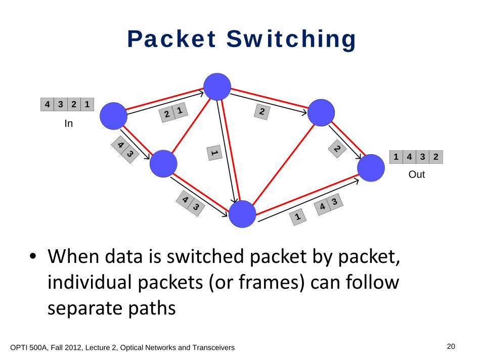
• When data is switched packet by packet, individual packets (or frames) can follow separate paths
20
Packet Switching
14 3 2
21 4 3
31
4
12
43
43
2
1 2
In
Out
OPTI 500A, Fall 2012, Lecture 2, Optical Networks and Transceivers

21
Network Classification by Switching Type
CommunicationNetworks
Circuit Switched
BroadcastNetworks
Switched Networks
Packet Switched
SONET
Ethernet
EthernetIP
• There is no switching in broadcast networks • Ethernet networks often contain broadcast regions connected by
packet switches
Data Communications
Telecommunications
OPTI 500A, Fall 2012, Lecture 2, Optical Networks and Transceivers

22
SONET Uses Binary, Amplitude Modulated, Non-Return-to-Zero Coding
Non-Return-to-Zero (NRZ) Coding
Return-to-Zero (RZ) Coding
Bit Period
1 1 1 1
0 0 0 0
1 1 1 1
0 0 0 0
OPTI 500A, Fall 2012, Lecture 2, Optical Networks and Transceivers

23
Phase, Amplitude, and In-Phase and Quadrature Modulation
“Coherent Optical Communications: Historical Perspectives and Future Directions”, Kazuro Kikuchi, in High Spectral Density Optical Communication Technologies (Springer Verlag, 2010)
OPTI 500A, Fall 2012, Lecture 2, Optical Networks and Transceivers

• Network convergence refers to the use of both datacom and telecom protocols and hardware in the same network.
• The motivation is to share resources and to combine the flexibility of datacom networks with the high capacity and Quality of Service assurance of telecom networks
24
Network Convergence
OPTI 500A, Fall 2012, Lecture 2, Optical Networks and Transceivers

• The communication infrastructure has evolved so that complicated convergence schemes like this are widely used today
• People agree that simplification would be a good thing
25
A More Fully Converged Network
ATM
IP
MPLS
SONET
WDM
OPTI 500A, Fall 2012, Lecture 2, Optical Networks and Transceivers

• IP is here to stay • So is WDM • The question is how to most efficiently build networks
that use both • Real world solutions must take into account the
current network infrastructure
26
“IP over WDM”
IP
?
WDM
OPTI 500A, Fall 2012, Lecture 2, Optical Networks and Transceivers

27
An Optical Transceiver
Optical Receiver
ElectricalOutput
LA/AGC TIA
Photo-diode
DiodeLaser
Driver Electrical
Input
OpticalOutput
OpticalInput
CDR
MOD
Optical Transmiter
MOD = Optical Modulator TIA = Transimpedance Amplifier LA = Limiting Amplifier AGC = Automatic Gain Control CDR = Clock and Data Recovery
OPTI 500A, Fall 2012, Lecture 2, Optical Networks and Transceivers
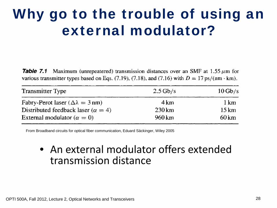
• An external modulator offers extended transmission distance
28
Why go to the trouble of using an external modulator?
From Broadband circuits for optical fiber communication, Eduard Säckinger, Wiley 2005
OPTI 500A, Fall 2012, Lecture 2, Optical Networks and Transceivers

• The transmitter includes components for control of temperature and average power
• A transmitter may contain circuitry for re-shaping and re-timing data
OPTI 500, Spring 2012, Lecture 8, Optical Transmitters 29
The Inside of an Optical Transmitter

30
Basic Laser/Modulator Drive Circuitry
V
DD
R Laser/Optical ModulatorLoad
CurrentSource
Q1 Q2
OPTI 500A, Fall 2012, Lecture 2, Optical Networks and Transceivers

• A constant current to the ground through the current source avoids current transients due to parasitic capacitances and inductances
31
Why do we use current steering? V
DD
R Laser/Optical ModulatorLoad
CurrentSource
Q1 Q2
OPTI 500A, Fall 2012, Lecture 2, Optical Networks and Transceivers

• The differential design is insensitive to common-mode noise and avoids the need for an input reference voltage
32
Why do we use differential input? V
DD
R Laser/Optical ModulatorLoad
CurrentSource
Q1 Q2
from Broadband Circuits for Optical Fiber Communication, Eduard Säckinger, Wiley 2005
OPTI 500A, Fall 2012, Lecture 2, Optical Networks and Transceivers

• The predriver conditions the signals for input to transistors Q1 and Q2
33
Drive Circuitry with an Additional Predriver
PredriverDD
R Laser/Optical ModulatorLoad
CurrentSource
Q1 Q2
OPTI 500A, Fall 2012, Lecture 2, Optical Networks and Transceivers

• The resistor Rs, dampens current oscillations due to parasitic inductances in the circuitry
34
Laser Load for the Drive Circuitry
Rs
SemiconductorLaser
(a)
OPTI 500A, Fall 2012, Lecture 2, Optical Networks and Transceivers

• Load is a transmission line • Modulator is AC coupled to the drive circuitry by inductor
RFC1 (RF Choke 1) and capacitor C1 (the combination is know as a “Bias T”)
• A Bias voltage Vb is DC coupled to the modulator by RFC2 • The resistor Rp generates the voltage signal on the modulator • The capacitor C2 blocks DC current through the modulator
35
Optical Modulator for the Drive Circuitry
Vb
RFC1
C1 C2Mach-ZenderModulator
Rp
RFC2
(b)
OPTI 500A, Fall 2012, Lecture 2, Optical Networks and Transceivers

36
An Optical Transceiver
Optical Receiver
ElectricalOutput
LA/AGC TIA
Photo-diode
DiodeLaser
Driver Electrical
Input
OpticalOutput
OpticalInput
CDR
MOD
Optical Transmiter
MOD = Optical Modulator TIA = Transimpedance Amplifier LA = Limiting Amplifier AGC = Automatic Gain Control CDR = Clock and Data Recovery
OPTI 500A, Fall 2012, Lecture 2, Optical Networks and Transceivers

37
Simple Pre-Amplifiers for Optical Receivers
from Broadband Circuits for Optical Fiber Communication, Eduard Säckinger, Wiley 2005
Quiet but Slow
Noisy but Fast
4signal signal
noise
V RI
kTIR
RCτ
=
=
=
OPTI 500A, Fall 2012, Lecture 2, Optical Networks and Transceivers

38
Transimpedance Amplifers
Quiet and Fast
4
~1
signal F signal
noiseF
F
V R I
kTIR
R CA
τ
=
=
+
OPTI 500A, Fall 2012, Lecture 2, Optical Networks and Transceivers

39
Limiting Amplifiers
From Fiber Optics Engineering, by Mohammad Azade, Springer Verlag, 2009
OPTI 500A, Fall 2012, Lecture 2, Optical Networks and Transceivers

40
Clock and Data Recovery
From Fiber Optics Engineering, by Mohammad Azade, Springer Verlag, 2009
OPTI 500A, Fall 2012, Lecture 2, Optical Networks and Transceivers
The Circuits and Filters Handbook, Third Edition . edited by Wai-Kai Chen, Section 59, 2003

41
A DP-QPSK Transmitter
From “Multilevel Modulation Formats Push Capacities Beyond 100 Gbits/sec,” Shubhashish, Data, and Crawford, In Laser Focus World, February, 2012, pp. 58-63.
OPTI 500A, Fall 2012, Lecture 2, Optical Networks and Transceivers

42
DP-QPSK Receiver
OPTI 500A, Fall 2012, Lecture 2, Optical Networks and Transceivers