Embed Size (px)
Citation preview

Cisco Systems, Inc.All contents are Copyright © 1992–2004 Cisco Systems, Inc. All rights reserved. Important Notices and Privacy Statement.
Page 1 of 15
DATA SHEET
OPTICAL FILTER PORTFOLIO FOR THE CISCO ONS 15454MULTISERVICE TRANSPORT PLATFORM
The Cisco ® ONS 15454 Multiservice Transport Platform (MSTP) provides a comprehensive, intelligent dense
wavelength-division multiplexing (DWDM) solution for expanding metropolitan (metro) and regional bandwidth.
Figure 1
Optical Filter Family
PRODUCT OVERVIEW
The Cisco ONS 15454 MSTP offers a comprehensive selection of optical filters, shown in Figure 1, for delivering the correct amount of
bandwidth to each service location in a metro or regional network. The filter cards are part of the Cisco ONS 15454 MSTP intelligent
DWDM architecture engineered to reducing DWDM complexity and speeding the deployment of next-generation networking solutions.
The Cisco ONS 15454 optical filter cards are plug-in modules that take advantage of the proven Cisco ONS 15454 carrier-class features to
deliver the flexibility to access network bandwidth from a single DWDM channel all the way to 32 channels, to support the requirements
of service provider and enterprise networks. Table 1 outlines the optical filter plug-in module types available for the Cisco ONS 15454
MSTP with the applications they are designed to support.

Cisco Systems, Inc.All contents are Copyright © 1992–2004 Cisco Systems, Inc. All rights reserved. Important Notices and Privacy Statement.
Page 2 of 15
Table 1. Optical Filter Cards with Applications
Component Deployment Application
32-channel ReconfigurableOptical Add-DropMultiplexer (ROADM)
This product provides wavelength access (on and off ramp) for all of the channels in a fiber cable.Often these are the only node types deployed in a network allowing software provisioningindividual wavelengths to add-drop, pass, or drop and pass through a service provider central officeor enterprise telecommunications facility. This offers in-service turn up of WLs without any need forprotection switching or physical upgrade of the DWDM system.
32-channel multiplexerand demultiplexer
This product provides wavelength access (on or off ramp) for all the channels in a fiber cable.Typically deployment locations are terminal hub sites, including service provider central offices orenterprise telecommunications facilities.
Band-Optical add/dropfilters (B-OADM)
These filters allow access (add/drop) to a band or bands of frequencies from a fiber cable whilepassing the remaining frequencies. They are typically deployed at intermediate sites where accessto larger amounts of bandwidth is required. They can also be inserted where future access tobandwidth may be required.
Channel-Optical add/dropfilters (C-OADM)
These filters enable access (add/drop) to individual wavelengths from a fiber cable while allowingthe remaining frequencies to pass. They are deployed at intermediate sites where access toindividual wavelengths is necessary. Channel-OADM filters can be cascaded to provide from 1- to32-channel add/drop capabilities.
Four-channelmultiplexer/demultiplexer( 4 M D )
This product provides wavelength access (on or off ramp) to four channels from a band-OADMfilter. They are deployed at intermediate sites where access to individual wavelengths isnecessary.
The Cisco ONS 15454 filter cards are based on the ITU 100-GHz wavelength plan. Each card integrates software-controllable variable
optical attenuators (VOAs), providing node- and network-based automatic-power-level management. The optical cards incorporate
faceplate-mounted LEDs to provide a quick visual check of the operational status at the card. Printed on each of the faceplates is an icon,
an orange circle, which is mapped to shelf-slot icons indicating the shelf slot where the card can be physically installed. The cards are
supported by the integrated Cisco ONS 15454 Cisco Transport Controller craft manager, which provides the user access for operations,
administration, maintenance, and provisioning (OAM&P) for the system.
Selection and deployment of the optical filters depends on the requirements of the network. The Cisco MetroPlanner optical design tool is
available to assist in the engineering, bill-of-material development, and deployment of the DWDM network. Figures 2 through 5 show
sample signal-flow diagrams for a selection of Cisco ONS 15454 MSTP node types, outlining the use for each filter type.

Cisco Systems, Inc.All contents are Copyright © 1992–2004 Cisco Systems, Inc. All rights reserved. Important Notices and Privacy Statement.
Page 3 of 15
Figure 2
MSTP ROADM Node
Figure 3
MSTP Hub Node

Cisco Systems, Inc.All contents are Copyright © 1992–2004 Cisco Systems, Inc. All rights reserved. Important Notices and Privacy Statement.
Page 4 of 15
Figure 4
Terminal Node
Figure 5
Active Optical Add/Drop Multiplexer (OADM) Node
Cisco Systems, Inc.All contents are Copyright © 1992–2004 Cisco Systems, Inc. All rights reserved. Important Notices and Privacy Statement.
Page 5 of 15
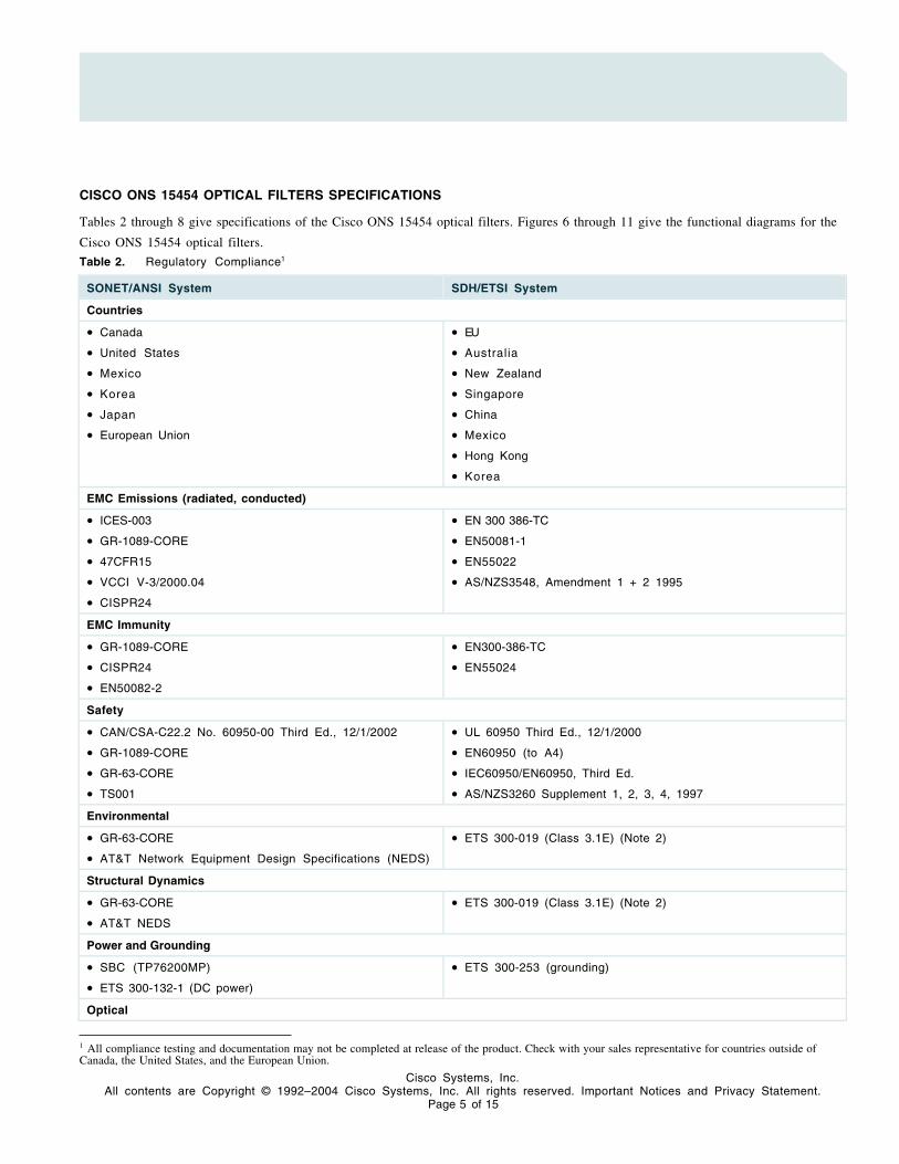
CISCO ONS 15454 OPTICAL FILTERS SPECIFICATIONS
Tables 2 through 8 give specifications of the Cisco ONS 15454 optical filters. Figures 6 through 11 give the functional diagrams for the
Cisco ONS 15454 optical filters.
Table 2. Regulatory Compliance1
SONET/ANSI System SDH/ETSI System
Countries
• Canada
• United States
• Mexico
• Korea
• Japan
• European Union
• EU
• Australia
• New Zealand
• Singapore
• China
• Mexico
• Hong Kong
• Korea
EMC Emissions (radiated, conducted)
• ICES-003
• GR-1089-CORE
• 47CFR15
• VCCI V-3/2000.04
• CISPR24
• EN 300 386-TC
• EN50081-1
• EN55022
• AS/NZS3548, Amendment 1 + 2 1995
EMC Immunity
• GR-1089-CORE
• CISPR24
• EN50082-2
• EN300-386-TC
• EN55024
Safety
• CAN/CSA-C22.2 No. 60950-00 Third Ed., 12/1/2002
• GR-1089-CORE
• GR-63-CORE
• TS001
• UL 60950 Third Ed., 12/1/2000
• EN60950 (to A4)
• IEC60950/EN60950, Third Ed.
• AS/NZS3260 Supplement 1, 2, 3, 4, 1997
Environmental
• GR-63-CORE
• AT&T Network Equipment Design Specifications (NEDS)
• ETS 300-019 (Class 3.1E) (Note 2)
Structural Dynamics
• GR-63-CORE
• AT&T NEDS
• ETS 300-019 (Class 3.1E) (Note 2)
Power and Grounding
• SBC (TP76200MP)
• ETS 300-132-1 (DC power)
• ETS 300-253 (grounding)
Optical
1 All compliance testing and documentation may not be completed at release of the product. Check with your sales representative for countries outside ofCanada, the United States, and the European Union.

Cisco Systems, Inc.All contents are Copyright © 1992–2004 Cisco Systems, Inc. All rights reserved. Important Notices and Privacy Statement.
Page 6 of 15
SONET/ANSI System SDH/ETSI System
• GR-253-CORE
• G.692
Quality
• TR-NWT-000332, Issue 4, Method 1 calculation for 20-year mean time between failure (MTBF)
Table 3. System Requirements
Component Cisco ONS 15454 SONET/ANSI Cisco ONS 15454 SDH/ETSI
Processor TCC2 TCC2
Cross-connect All (not required) All (not required)
Shelf assembly 15454-SA-ANSI or 15454-SA-HD shelf assemblywith FTA3 version fan-tray assembly
15454-SA-ETSI shelf assembly with SDH48V fan-tray assembly
System software Release 4.6.0 SONET or greater
Release 4.7.0 SONET or greater for 15454-32-WSS and 15454-32-DMX
Release 4.6.0 SDH or greater
Release 4.7.0 SDH or greater for 15454E-32-WSS and 15454E-32-DMX
Table 4. Common Filter Specifications
Specification 32-Channel Multiplexer 32-Channel Demultiplexer4-ChannelMultiplexer/Demultiplexer
Management
Card LEDs
Failure (FAIL)
Active/standby (ACT/STBY)
Signal fail (SF)
Red
Green/yellow
Yellow
Red
Green/yellow
Yellow
Red
Green/yellow
Yellow
Operating Environment
Temperature –5 to 55°C
23 to 131°F
–5 to 55°C
23 to 131°F
–5 to 55°C
23 to 131°F
Humidity 5 to 95% noncondensing 5 to 95% noncondensing 5 to 95% noncondensing
Storage Environment
Temperature –40 to 185°F
–40 to 85°C
–40 to 185°F
–40 to 85°C
–40 to 185°F
–40 to 85°C
Humidity 5 to 95% noncondensing 5 to 95% noncondensing 5 to 95% noncondensing
Cisco Systems, Inc.All contents are Copyright © 1992–2004 Cisco Systems, Inc. All rights reserved. Important Notices and Privacy Statement.
Page 7 of 15
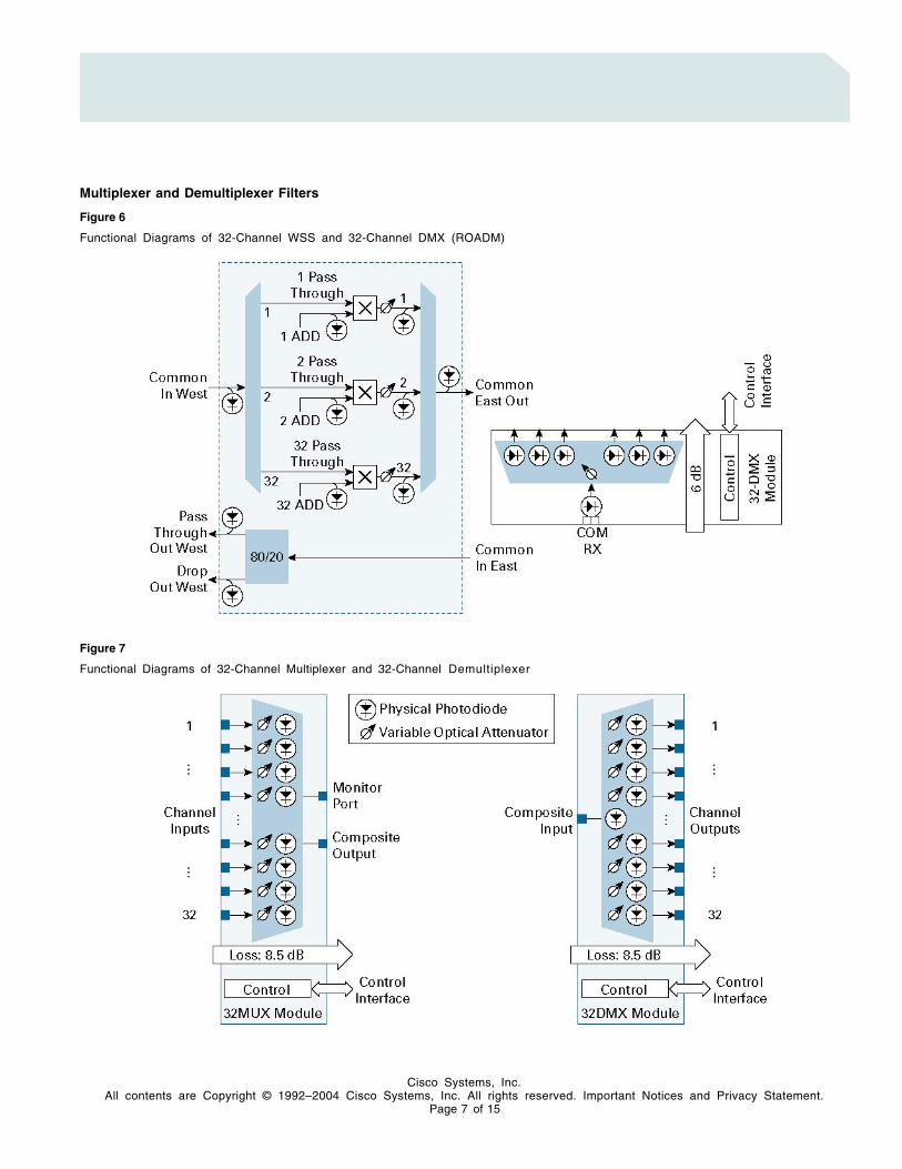
Multiplexer and Demultiplexer Filters
Figure 6
Functional Diagrams of 32-Channel WSS and 32-Channel DMX (ROADM)
Figure 7
Functional Diagrams of 32-Channel Multiplexer and 32-Channel Demultiplexer

Cisco Systems, Inc.All contents are Copyright © 1992–2004 Cisco Systems, Inc. All rights reserved. Important Notices and Privacy Statement.
Page 8 of 15
Figure 8
Functional Diagram of 4-Channel Multiplexer/Demultiplexer
Table 5. Specifications for 32-Channel WSS, 32-Channel DMX, 32-Channel Multiplexer, 32-Channel Demultiplexer, and 4-ChannelMultiplexer/Demultiplexer
Specification 32-Channel WSS32-ChannelD M X 32-Channel MUX
32-ChannelDEMUX
4-Channel Mux/Demux
Optical Parameters
Insertion loss (maximum @minimum VOA)
Drop or add
Monitor
11.3 dB (EXP RX –COM TX)
1.5 dB (COM RX –EXP – TX)
7.6 dB (Add 1-32 –COM TX)
8.5 dB (COM RX –DROP TX)
5.5 dB 8.5 dB
29.5 dB
8.5 dB
–
3.6(multiplexer),3.3(demultiplexer)
–
VOA dynamic range 20 dB Express25 dB Add
25 dB 25 dB 25 dB 30 dB
Maximum input power 300 mW 300 mW 25 dBm 25 dBm 300 mW
Filter type Array wave guide(AWG)
Array waveguide (AWG)
Array waveguide (AWG)
Array waveguide (AWG)
Interferential
Transmit Filter passband (@0.5 dB resolution bandwidth)
+/– 0.115 nmExpress+/– 0.135 nm Add
+/– 0.11 nm +/– 0.18 nm +/– 0.18 nm +/– 0.18 nm

Cisco Systems, Inc.All contents are Copyright © 1992–2004 Cisco Systems, Inc. All rights reserved. Important Notices and Privacy Statement.
Page 9 of 15
Specification 32-Channel WSS32-ChannelD M X 32-Channel MUX
32-ChannelDEMUX
4-Channel Mux/Demux
Connectors
Channel input (multiplexer)and Output (demultiplexer)ports
Composite ports
Monitor ports
MPO
LC
–
MPO
LC
–
MPO
LC
LC
MPO
LC
–
LC
LC
–
Power
Card power draw
Typical
Maximum
44W
60W
15W
25W
16W
31W
16W
31W
17W
25W
Physical
Size 2 slots 1 slot 2 slots 1 slot 1 slot
Supported shelf slots 1 and 2, 3 and 4, 5and 6, 12 and 13,14 and 15, 16 and17
1–6, 12–17 1 and 2, 3 and 4,5 and 6, 12 and13, 14 and 15, 16and 17
1–6, 12–17 1–6, 12–17
Optical Add/Drop Filters
Figure 9
Functional Diagrams for One and Two-Channel OADM

Cisco Systems, Inc.All contents are Copyright © 1992–2004 Cisco Systems, Inc. All rights reserved. Important Notices and Privacy Statement.
Page 10 of 15
Figure 10
Functional Diagram for Four-Channel OADM Functional Diagrams
Table 6. Specifications for Channel OADM Filter Specifications
Specification One-Channel OADM Two-Channel OADM Four-Channel OADM
Optical Parameters
Insertion loss (maximum)
Drop (maximum)
Add (@ minimum VOA)
Express (maximum from express inputto composite output)
Express (maximum from compositeinput to express output)
2 dB
2.6 dB
1.2 dB
2.4 dB
2.4 dB
3.1 dB
1.6 dB
2.7 dB
5.5 dB
4.9 dB
1.2 dB
2.7 dB
VOA dynamic range 30 dB 30 dB 30 dB
Maximum input power 300 mW 300 mW 300 mW
Filter type Interferential Interferential Interferential
Filter passband (@ 0.5 dB resolutionbandwidth)
Transmit
Receive
+/– 0.18 nm
+/– 0.18 nm
+/– 0.18 nm
+/– 0.18 nm
+/– 0.18 nm
See Table 7

Cisco Systems, Inc.All contents are Copyright © 1992–2004 Cisco Systems, Inc. All rights reserved. Important Notices and Privacy Statement.
Page 11 of 15
Specification One-Channel OADM Two-Channel OADM Four-Channel OADM
Connectors
Input/output ports
Monitor ports
LC
LC
LC
LC
LC
LC
Power
Card power draw
Typical
Maximum
17W
25W
17W
25W
17W
25W
Physical
Size 1 slot 1 slot 1 slot
Supported shelf slots 1–6, 12–17 1–6, 12–17 1–6, 12–17
Table 7. Optical Filter Bandwidth [RfxBW2] @ –1 dB of the Four-Channel OADM Cards
Receive (Express) BandSub-band of Transmit (dropped)Channels Left Side (nm) Right Side (nm)
30.3 – _ ≥ 1533.825
34.2 _ ≤ 1533.395 _ ≥ 1537.765
38.1 _ ≤ 1537.325 _ ≥ 1541.715
42.1 _ ≤ 1541.275 _ ≥ 1545.695
46.1 _ ≤ 1545.245 _ ≥ 1549.695
50.1 _ ≤ 1549.235 _ ≥ 1553.705
54.1 _ ≤ 1553.255 _ ≥ 1557.745
58.1 _ ≤ 1557.285 –

Cisco Systems, Inc.All contents are Copyright © 1992–2004 Cisco Systems, Inc. All rights reserved. Important Notices and Privacy Statement.
Page 12 of 15
Figure 11
One- and Four-Band OADM Functional Diagrams
Table 8. Band OADM Filter Specifications
Specification One-Band OADM Four-Band OADM
Optical Parameters
Insertion loss (maximum)
Drop path (@ minimum VOA)
Add path
Express—From express input to compositeoutput
Express—From composite input to expressoutput (@ minmum VOA)
3 dB
2.2 dB
1.6 dB
2.9 dB
4.5 dB
3.5 dB
3 dB
4.9 dB
VOA dynamic range 30 dB 30 dB
Maximum input power 25 dBm 25 dBm
Filter type Interferential Interferential
Filter passband (@–1 dB) 3.6 nm 3.6 nm
Connectors
Input/output ports
Monitor ports
LC
LC
LC
LC
Power
Card power draw
Typical
Maximum
17W
25W
17W
25W

Cisco Systems, Inc.All contents are Copyright © 1992–2004 Cisco Systems, Inc. All rights reserved. Important Notices and Privacy Statement.
Page 13 of 15
Specification One-Band OADM Four-Band OADM
Physical
Size 1 slot 1 slot
Supported shelf slots 1–6, 12–17 1–6, 12–17
ORDERING INFORMATION
Tables 9 and 10 give ordering information for the Cisco ONS 15454.
Table 9. System Ordering Information 2
Part Number Description
15454-32-WSS
15454E-32-WSS
32 Ch Wavelength Selective Switch
15454-32-DMX
15454E-32-DMX
32 Ch DMUX 100 GHz (for use with 32.WSS)
15454-32MUX-O
15454E-32MUX-O
32-channel multiplexer card, 100 GHz, monitor port, 8-fiber multipath push-on (MPO) connector
15454-32DMX-O
15454E-32DMX-O
32-channel demultiplexer card, 100 GHz, monitor port, 8-fiber MPO connector
15454-4MD-xx.x
15454E-4MD-xx.x
4-channel multiplexer and demultiplexer card, 100 GHz, LC connector
15454-AD-1C-xx.x
15454E-AD-1C-xx.x
1-channel optical add/drop multiplexer, 100 GHz, LC connector
15454-AD-2C-xx.x
15454E-AD-2C-xx.x
2-channel optical add/drop multiplexer, 100 GHz, LC connector
15454-AD-4C-xx.x
15454E-AD-4C-xx.x
4-channel optical add/drop multiplexer, 100 GHz, LC connector
15454-AD-1B-xx.x
15454E-AD-1B-xx.x
1-band optical add/drop multiplexer, 100 GHz, LC connector
15454-AD-4B-xx
15454E-AD-4B-xx
4-band optical add/drop multiplexer, 100 GHz, LC connector
Table 10. Wavelength Ordering Information
Wavelength Cisco 32-Channel Plan AD-1C AD-2C AD-4C AD-1B AD-4B
1530.33 X 30.3 30.3 30.3 30.3 30.3
1531.12 X 31.1 30.3 30.3 30.3 30.3
1531.90 X 31.9 31.9 30.3 30.3 30.3
1532.68 X 32.6 31.9 30.3 30.3 30.3
1533.47
1534.25 X 34.2 34.2 34.2 34.2 30.3
2 * xx.x in the part number indicates the ordering wavelength of the card (example: 1530.33 = 30.3). Refer to Table 9 for wavelength plan. Letter “E” in part number indicatescompatibility with SDH/ETSI system.

Cisco Systems, Inc.All contents are Copyright © 1992–2004 Cisco Systems, Inc. All rights reserved. Important Notices and Privacy Statement.
Page 14 of 15
Wavelength Cisco 32-Channel Plan AD-1C AD-2C AD-4C AD-1B AD-4B
1535.04 X 35.0 32.2 34.2 34.2 30.3
1535.82 X 35.8 35.8 34.2 34.2 30.3
1536.61 X 26.6 35.8 34.2 34.2 30.3
1537.40
1538.19 X 38.1 38.1 38.1 38.1 30.3
1538.98 X 38.9 38.1 38.1 38.1 30.3
1539.77 X 39.7 39.7 38.1 38.1 30.3
1540.56 X 40.5 39.7 38.1 38.1 30.3
1541.35
1542.14 X 42.1 42.1 42.1 42.1 30.3
1542.94 X 42.9 42.1 42.1 42.1 30.3
1543.73 X 43.7 43.7 42.1 42.1 30.3
1544.53 X 44.5 43.7 42.1 42.1 30.3
1545.32
1546.12 X 46.1 46.1 46.1 46.1 46.1
1546.92 X 46.9 46.1 46.1 46.1 46.1
1547.72 X 47.7 47.7 46.1 46.1 46.1
1548.51 X 48.5 47.7 46.1 46.1 46.1
1549.32
1550.12 X 50.1 50.1 50.1 50.1 46.1
1550.92 X 50.9 50.1 50.1 50.1 46.1
1551.72 X 51.7 51.7 50.1 50.1 46.1
1552.52 X 52.5 51.7 50.1 50.1 46.1
1553.33
1554.13 X 54.1 54.1 54.1 54.1 46.1
1554.94 X 54.9 54.1 54.1 54.1 46.1
1555.75 X 55.7 55.7 54.1 54.1 46.1
1556.55 X 56.5 56.5 54.1 54.1 46.1
1557.36
1558.17 X 58.1 58.1 58.1 58.1 46.1
1558.98 X 58.9 58.1 58.1 58.1 46.1
1559.79 X 59.7 59.7 58.1 58.1 46.1
1560.61 X 60.6 59.7 58.1 58.1 46.1

Cisco Systems, Inc.All contents are Copyright © 1992–2004 Cisco Systems, Inc. All rights reserved. Important Notices and Privacy Statement.
Page 15 of 15
Corporate HeadquartersCisco Systems, Inc.170 West Tasman DriveSan Jose, CA 95134-1706USAwww.cisco.comTel: 408 526-4000
800 553-NETS (6387)Fax:408 526-4100
European HeadquartersCisco Systems International BVHaarlerbergparkHaarlerbergweg 13-191101 CH AmsterdamThe Netherlandswww-europe.cisco.comTel: 31 0 20 357 1000Fax:31 0 20 357 1100
Americas HeadquartersCisco Systems, Inc.170 West Tasman DriveSan Jose, CA 95134-1706USAwww.cisco.comTel: 408 526-7660Fax:408 527-0883
Asia Pacific HeadquartersCisco Systems, Inc.168 Robinson Road#28-01 Capital TowerSingapore 068912www.cisco.comTel: +65 6317 7777Fax: +65 6317 7799
Cisco Systems has more than 200 offices in the following countries and regions. Addresses, phone numbers, and fax numbers are listed onthe Cisco Website at www.cisco.com/go/offices.
Argentina • Australia • Austria • Belgium • Brazil • Bulgaria • Canada • Chile • China PRC • Colombia • Costa RicaCroatia • Cyprus • Czech Republic • Denmark • Dubai, UAE • Finland • France • Germany • Greece • Hong Kong SARHungary • India • Indonesia • Ireland • Israel • Italy • Japan • Korea • Luxembourg • Malaysia • MexicoThe Netherlands • New Zealand • Norway • Peru • Philippines • Poland • Portugal • Puerto Rico • Romania • RussiaSaudi Arabia • Scotland • Singapore • Slovakia • Slovenia • South Africa • Spain • Sweden • Switzerland • TaiwanThailand • Turkey • Ukraine • United Kingdom • United States • Venezuela • Vietnam • Zimbabwe
Copyright 2004 Cisco Systems, Inc. All rights reserved. Cisco, Cisco Systems, and the Cisco Systems logo are registered trademarks or trademarks of CiscoSystems, Inc. and/or its affiliates in the United States and certain other countries.
All other trademarks mentioned in this document or Website are the property of their respective owners. The use of the word partner does not imply a partnershiprelationship between Cisco and any other company. (0403R) HU/LW6442 06/04
Printed in the USA