Embed Size (px)
Citation preview
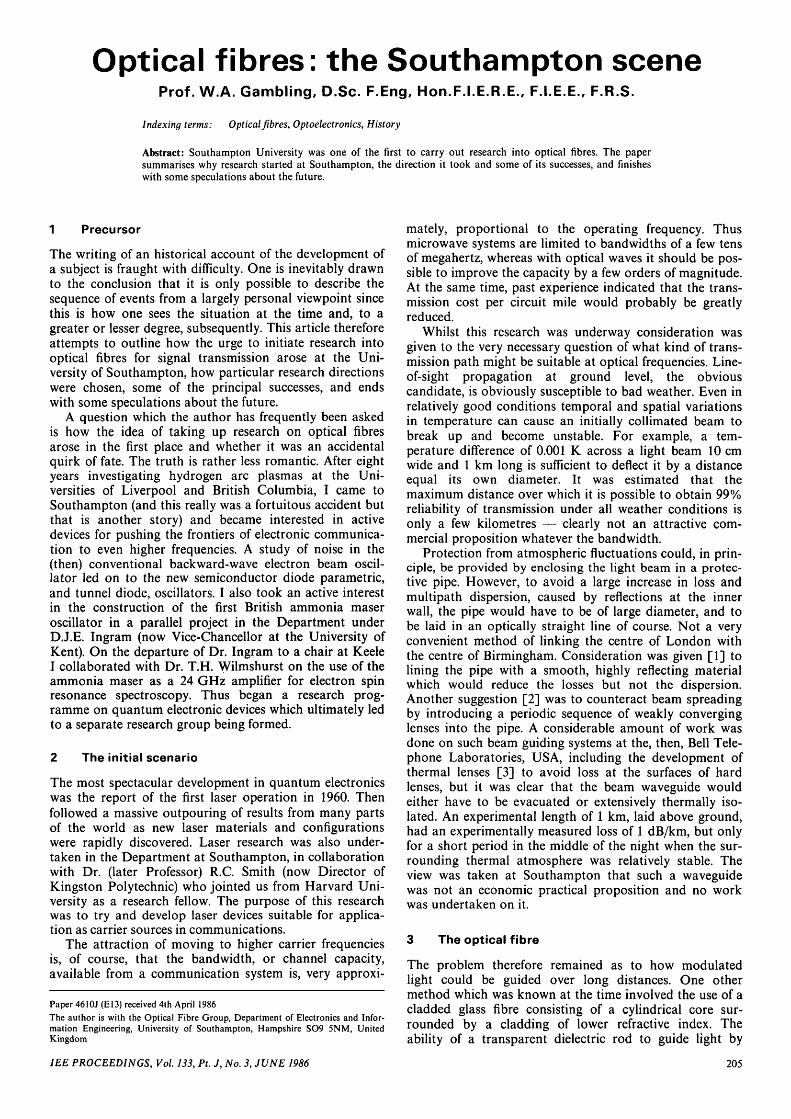
Optical fibres: the Southampton sceneProf. W.A. Gambling. D.Sc. F.Eng. Hon.F. I .E.RE. , F.I.E.E., F.R.S.
Indexing terms: Optical fibres, Optoelectronics, History
Abstract: Southampton University was one of the first to carry out research into optical fibres. The papersummarises why research started at Southampton, the direction it took and some of its successes, and finisheswith some speculations about the future.
1 Precursor
The writing of an historical account of the development ofa subject is fraught with difficulty. One is inevitably drawnto the conclusion that it is only possible to describe thesequence of events from a largely personal viewpoint sincethis is how one sees the situation at the time and, to agreater or lesser degree, subsequently. This article thereforeattempts to outline how the urge to initiate research intooptical fibres for signal transmission arose at the Uni-versity of Southampton, how particular research directionswere chosen, some of the principal successes, and endswith some speculations about the future.
A question which the author has frequently been askedis how the idea of taking up research on optical fibresarose in the first place and whether it was an accidentalquirk of fate. The truth is rather less romantic. After eightyears investigating hydrogen arc plasmas at the Uni-versities of Liverpool and British Columbia, I came toSouthampton (and this really was a fortuitous accident butthat is another story) and became interested in activedevices for pushing the frontiers of electronic communica-tion to even higher frequencies. A study of noise in the(then) conventional backward-wave electron beam oscil-lator led on to the new semiconductor diode parametric,and tunnel diode, oscillators. I also took an active interestin the construction of the first British ammonia maseroscillator in a parallel project in the Department underD.J.E. Ingram (now Vice-Chancellor at the University ofKent). On the departure of Dr. Ingram to a chair at Keele1 collaborated with Dr. T.H. Wilmshurst on the use of theammonia maser as a 24 GHz amplifier for electron spinresonance spectroscopy. Thus began a research prog-ramme on quantum electronic devices which ultimately ledto a separate research group being formed.
2 The initial scenario
The most spectacular development in quantum electronicswas the report of the first laser operation in 1960. Thenfollowed a massive outpouring of results from many partsof the world as new laser materials and configurationswere rapidly discovered. Laser research was also under-taken in the Department at Southampton, in collaborationwith Dr. (later Professor) R.C. Smith (now Director ofKingston Polytechnic) who jointed us from Harvard Uni-versity as a research fellow. The purpose of this researchwas to try and develop laser devices suitable for applica-tion as carrier sources in communications.
The attraction of moving to higher carrier frequenciesis, of course, that the bandwidth, or channel capacity,available from a communication system is, very approxi-
Paper 4610J (El3) received 4th April 1986
The author is with the Optical Fibre Group, Department of Electronics and Infor-mation Engineering, University of Southampton, Hampshire SO9 5NM, UnitedKingdom
mately, proportional to the operating frequency. Thusmicrowave systems are limited to bandwidths of a few tensof megahertz, whereas with optical waves it should be pos-sible to improve the capacity by a few orders of magnitude.At the same time, past experience indicated that the trans-mission cost per circuit mile would probably be greatlyreduced.
Whilst this research was underway consideration wasgiven to the very necessary question of what kind of trans-mission path might be suitable at optical frequencies. Line-of-sight propagation at ground level, the obviouscandidate, is obviously susceptible to bad weather. Even inrelatively good conditions temporal and spatial variationsin temperature can cause an initially collimated beam tobreak up and become unstable. For example, a tem-perature difference of 0.001 K across a light beam 10 cmwide and 1 km long is sufficient to deflect it by a distanceequal its own diameter. It was estimated that themaximum distance over which it is possible to obtain 99%reliability of transmission under all weather conditions isonly a few kilometres — clearly not an attractive com-mercial proposition whatever the bandwidth.
Protection from atmospheric fluctuations could, in prin-ciple, be provided by enclosing the light beam in a protec-tive pipe. However, to avoid a large increase in loss andmultipath dispersion, caused by reflections at the innerwall, the pipe would have to be of large diameter, and tobe laid in an optically straight line of course. Not a veryconvenient method of linking the centre of London withthe centre of Birmingham. Consideration was given [1] tolining the pipe with a smooth, highly reflecting materialwhich would reduce the losses but not the dispersion.Another suggestion [2] was to counteract beam spreadingby introducing a periodic sequence of weakly converginglenses into the pipe. A considerable amount of work wasdone on such beam guiding systems at the, then, Bell Tele-phone Laboratories, USA, including the development ofthermal lenses [3] to avoid loss at the surfaces of hardlenses, but it was clear that the beam waveguide wouldeither have to be evacuated or extensively thermally iso-lated. An experimental length of 1 km, laid above ground,had an experimentally measured loss of 1 dB/km, but onlyfor a short period in the middle of the night when the sur-rounding thermal atmosphere was relatively stable. Theview was taken at Southampton that such a waveguidewas not an economic practical proposition and no workwas undertaken on it.
3 The optical fibre
The problem therefore remained as to how modulatedlight could be guided over long distances. One othermethod which was known at the time involved the use of acladded glass fibre consisting of a cylindrical core sur-rounded by a cladding of lower refractive index. Theability of a transparent dielectric rod to guide light by
IEE PROCEEDINGS, Vol. 133, Pt. J, No. 3, JUNE 1986 205
total internal reflection had been known for a long time;but the existence of an evanescent field at the surface,together with the inevitable deterioration of the surface inthe atmosphere, rendered the device impracticable. Amuch more recent advance [4] had been the concept ofsurrounding the guiding rod with a second material, whichhad to be of lower refractive index to retain the possibilityof total internal reflection, thereby protecting the reflectingsurface and providing a shielded region for the evanescentfield. The two materials, core and cladding, had to bephysically and chemically compatible and capable of beingdrawn down to a small diameter if the structure were tohave any degree of flexibility. Such cladded glass fibres hadbeen fabricated and made up into bundles to provide flex-ible light guidance in medical endoscopes. However, theattenuation of the fibres was so high that propagation wasonly possible over distances of a metre or two, whilst thestrength was so poor that normal handling of the bundleswould cause breakage of individual fibres to a noticeabledegree. They were therefore totally unsuitable for long-distance transmission.
Nevertheless, some thought was being given to thepotential use of optical fibres [5, 6]. For example, in anaddress to the British Association for the Advancement ofScience at Southampton in 1964 I discussed existing workon unguided propagation and beam waveguides and wenton to speculate about the potential applicability of opticalfibres. I recall being questioned closely on the practicalitiesby the Director of Research of the (then) Post Office.However, serious interest was not aroused until the pub-lication of the now famous paper [7] of Kao andHockham in 1966. This paper was important in two majorrespects. First, it showed that one candidate optical fibrematerial, namely silica, might perhaps be capable of atransmission loss at visible wavelengths potentially lowenough for telecommunication purposes. Secondly, itaroused sufficient interest among funding bodies for threeresearch programmes to be supported. In addition toKao's work at STL, Harlow, a group was established atthe British Post Office Research Station, Dollis Hill,together with a joint research programme between theSignals Research and Development Establishment, Christ-church, Dorset, and my own group in the ElectronicsDepartment at Southampton University.
4 Starting from scratch
The SRDE/Southampton work, funded by the Ministry ofDefence, began in October 1966 to carry out a researchfeasibility study of a cheap, low bandwidth, optical fibrecommunications system suitable for distances of severalkilometres. The target was thus slightly different from thatof the groups at STL and BPO, who were aiming at thelongest possible distance and maximum bandwidth. Forour purpose multimode fibres would probably be suffi-cient, rather than the single-mode requirement of STL andBPO. It was decided that research on transmitters, re-ceivers, components and the system should be done atSRDE, while the University would study bulk glass andfibre properties and fibre fabrication techniques. Whilst inthe University group there was considerable experience inmicrowave and laser techniques, no-one had any knowl-edge of glass, nor the faintest idea of how to make fibres.Nothing daunted, the first research fellow was appointed,Dr. (now Professor) P.J.R. Laybourn, and a theoreticalstudy of propagation in fibres begun. Experimental workwas not to begin for another year because the contractsupporting the research, whilst agreed in principle in early
1966, was not to provide any hard cash until January1968, and the author was on sabbatical leave in the USAduring the academic year 1966/67.
The next stage was to find out what an optical fibrereally was by attempting to make one. The standardmethod at the time was the 'rod-in-tube' technique,whereby one takes a rod of core glass, places it inside atube of cladding glass, and the composite is placed in avertical furnace with a short hot zone and drawn downinto a fibre. Since we knew nothing about furnaces or fibredrawing, it seemed sensible to approach one of the majorglass companies in the UK to seek help and advice. Thiswe did and received neither. The only help we could getwas from a friendly electronics company who showed ustheir technique for drawing short rods into longer ones inthe preparation of fibre-optic faceplates. In addition, thewriter had seen precision-bore glass tubing being drawnfor travelling-wave tube devices. This paucity of knowledgeand assistance turned out to be a blessing in disguise,because not knowing what parameters were the criticalones the decision was taken to control everything to thehighest degree possible within a tall rigid structure. Thewire-wound drawing furnace had precise control of tem-perature (better than 0.1 °C) up to 1200°C and of drawingspeed (0.1%). The fibre drawing equipment was designedand constructed by Dr. D.N. Payne, who had joined theresearch group as a research student (and now is PirelliReader in Optical Fibres), and the success of the designmay be judged from the fact that this fibre drawing toweris still in everyday use.
At the same time equipment for the measurement oftransmission loss and scattering loss in bulk glasses wasbeing set up by another research student, Dr. J.P. Dakin.The difficulties here were considerable, in that the trans-mission losses being measured were tiny compared withend reflections on the samples and variations in transmit-ted intensity caused by inhomogeneities. Nevertheless,after much hard work, some successful double-beam spec-trophotometers were constructed [8] at bothSouthampton and STL, and classical measurementsdemonstrating the Rayleigh nature of scattering in bulk,high-quality, optical glasses were carried out.
5 The first measurements
Measurements on commercially available optical fibrebundles indicated transmission losses of several thousanddB per kilometre. After a study of likely starting materials,most of the early fibre fabrication was carried out withSchott F7 rods as core glass and Pilkington ME1 tubingas cladding. The first fibres drawn had an encouraging lossof about 1000 dB/km and, after a careful study of drawingconditions, this was reduced to 400 dB/km. At the time,about 1968, the author recalls with wry amusement beingwarmly congratulated on this result by R.B. Dyott of thePost Office Research Station. How times have changed!Further studies, including fibre annealing, brought the lossdown to 150 dB/km, which corresponded to that beingmeasured on the bulk starting rods. This result, whilstarchaic now, demonstrated that the effects of waveguideinhomogeneities could be reduced to a low level, at leastcompared with this magnitude of loss. Measurements oflight scatter, together with its dependence on scatteringangle, confirmed the Rayleigh mechanism and that the lossvalue was extremely small.
As well as studying fibre fabrication and the measure-ment of materials parameters, we were also studying thepotential bandwidth of our multimode fibres. This was
206 IEE PROCEEDINGS, Vol. 133, Pt. J, No. 3, JUNE 1986
expected to be small, as, if all possible modes were excitedin the fibres, the large spread in group velocities wouldlimit the bandwidth to 10 or 20 MHz over one kilometre.However we produced subnanosecond pulses by modelocking a helium/neon laser and were able to show [9]that, even in step-index multimode fibres, very much largerbandwidths are possible. This later culminated in the mea-surement of a bandwidth x length product in a liquid-cored fibre of 1 GHz km over a length of about akilometre [10], although this capacity was easily reduced ifmode conversion was allowed to occur.
6 The pace quickens
In the years up to 1970 there were not many laboratoriesworldwide studying optical-fibre transmission. In particu-lar, there had been a deafening silence from Bell TelephoneLaboratories. The reason for this was explained to me byRudi Kompfner some years later and after his retirementfrom Bell Laboratories. He said he was in charge of opticalcommunications research at the time and his materialsexperts had informed him that it would not be possible toreduce material losses to the level required for long-distance transmission. They therefore persevered with thework on the beam-guiding system. However in the late1960s he had a visitor from the UK who pointed out theprogress that was being made here and, said Kompfer,'work on optical fibres started at Bell Laboratories thenext day'! Interest was quickened much more strongly in1970 with the report [11] of a single-mode fibre loss of20 dB/km. No indication was given as to how it was done,or what materials had been used.
At Southampton we were feeling frustrated at beinglimited to commercially available starting materials andcould not afford the expensive equipment required tostudy the double-crucible method of fibre fabrication beingdeveloped at the Post Office Research Station. We had acollaborative programme with Professor H. Rawson at theUniversity of Sheffield where preforms were being pro-duced, from a double-layered melt, which we then drewinto fibre. By this technique we were able to produce shortlengths of fibre with 40 dB/km loss and a numerical aper-ture of 0.43, but the rate of supply of preforms was verylimited. In 1971 news reached us of the liquid-core silica-cladding fibre developed in Australia* [12] and we imme-diately saw this as a method of obtaining our ownin-house fibre supply and of gaining some experience inmeasurements and handling of low-loss fibres. Not, at thattime, having facilities for drawing silica tubing, requiring adrawing temperature of 2000 K, we searched for an alter-native core/cladding combination, and found that excellentfibres could be made with hexachlorobuta-l,3-diene inME1 soft-glass tubing [13]. Liquid-core fibres are prob-ably the most perfect step-index fibres ever made, in thesense that the core/cladding boundary is obviously verysharp. At no time did we see this fibre as being suitable forpractical installation, but it proved an excellent experimen-tal tool and enabled us to carry out some very good funda-mental work on fibres. We achieved [14] a transmissionloss of below 5.6 dB/km (the best in the world for severalyears) and, as indicated above, a bandwidth x lengthproduct of 1 GHz km. In fact we claim that this fibrecarried the first commercial television broadcast, in that aone-hour colour television broadcast was made by theBBC from The Royal Institution in London along a lengthof this fibre on the way to the transmitter.
* OGILVIE, G.J.: Comments made at Symposium on Optical Transmission,Imperial College, London, March 1972
1EE PROCEEDINGS, Vol. 133, Pt. J, No. 3, JUNE 1986
The cladding glass of the liquid-cored fibre was esti-mated to have a transmission loss of approaching10000 dB/km, but, because of the high numerical aperture,the effect on the total transmission loss was small. Thissomewhat surprising result was confirmed by other experi-ments and by theoretical analysis [15] which showed thata balance between numerical aperture and claddingattenuation could filter out high-order modes in a multi-mode fibre and thus compensate, to some extent, for modeconversion.
7 Frenetic fabrication
The situation with regard to fibre attenuation in the early1970s was as follows. Commercially available glasses pre-pared by conventional techniques were known to havehigh attenuation and were therefore not suitable. Anattenuation of 20 dB/km had been reported from CorningGlass Works and was thought to be made by depositinga soot of tinania-doped silica on the inside of a silica tubewhich was subsequently fused and drawn into a fibre.Liquid-cored fibres had been made with attenuations of afew dB/km, but these were not attractive for practicalapplication. For example, to fill a capillary tube of 100 ^minternal diameter and 1 kilometre length took about fourhours, even with a driving pressure of 1400 atmospheres.The filling time of a single-mode fibre would be four ordersof magnitude greater.
For many years bulk silica had been made by flamehydrolysis, starting with silicon tetrachloride, and theintrinsic loss of silica was known to be small. Silicon tetra-chloride is liquid at room temperature and can thereforebe relatively easily purified by successive fractional distilla-tion. However, the process of flame hydrolysis, wherebysilicon tetrachloride vapour is oxidised by heating in anoxy-hydrogen flame, introduces excess water into theresultant glass, which produces large absorption peaks inthe wavelength region of interest. Many laboratories weretackling the problem of fibre fabrication, and the com-petition to produce the required breakthrough was intense.It was also known, but perhaps not widely appreciated bythe potential fibre fabricators, that glass was being pro-duced in microcircuit fabrication by a form of chemicalvapour deposition in which the glass oxide was producedby oxidisation of the associated chloride. This was a heter-ogeneous process operating at low temperature with anextremely low rate of deposition totally inadequate forfibre fabrication.
Fibres had been drawn [16] from rods of silica coatedwith a boric oxide/silica glass layer and, more recently,with a modified core material apparently comprising amixture of silica and germania [17]. It should be pointedout that the addition of titania or germania to silica raisesthe refractive index, whilst boric oxide has the reverseeffect.
At Southampton we repeated the silica core/borosilicatecladding technique and found the numerical aperture wasquite small. We sought a method by which core and clad-ding materials could be deposited at a high rate whilstavoiding the use of flame hydrolysis and the associatedhigh water content. We achieved success in 1974 with atechnique [18] in which a homogeneous vapour-phasereaction takes place inside a substrate tube, and the sub-sequent fine soot deposition is simultaneously fused into aclear glass layer. The resulting fibre comprised a new corematerial (as far as optical fibres were concerned) of phos-phosilicate glass with a pure silica cladding region. Thisresult was announced in the Electro-Optics Conference in
207
Brighton during the discussion of a paper from STL [19]on a germanosilicate core/silica cladding fibre. We claimedthat our fabrication technique was novel, comprisinghomogeneous chemical vapour deposition and simulta-neous fusing of the deposited layers. The phosphosilicatecore composition was also novel and was found to havevery low loss, very low scattering and was much cheaperthan either germania or silica doping. In addition, themeasured transmission loss was lower than had been pre-dicted [20] for pure silica!
Word of our success reached Bell Telephone Labor-atories where a similar process had been devised whichthey called 'modified chemical vapour deposition', a termwhich is now generally used. They knew that our workhad been submitted for publication and therefore pulledout all the stops to get their work into print [21] in BellSystem Technical Journal. We were subsequently told(unofficially) that this was done in the record time of twoweeks, and a reading of these papers indicates that theywere obviously put together in a very great hurry. Thehomogeneous/modified chemical vapour depositionprocess rapidly became, and remains, the one most widelyused throughout the world. Through further developmentof this, and other, fabrication techniques, fibre losses havenow reached astonishingly low levels of a few tenths of adecibel per kilometre, giving rise to transmission distanceswithout repeaters of several hundred kilometres.
8 Single-mode or multimode?
As indicated earlier in this article, when optical fibre workbegan in the UK the efforts of the Post Office ResearchStation and STL were directed towards single-mode pro-pagation, whereas the Southampton/SRDE researchexplored the possibilities of multimode transmission. Thelatter work soon demonstrated that multimode fibrescould have bandwidth x length products approaching1 GHz km if mode conversion could be avoided, or com-pensated, by mode filtering or mode scrambling. A betterapproach, however, was to introduce a graded refractive-index distribution into the core of the multimode fibre toreduce intermode dispersion.
A graded-index distribution had been produced in thewell-known Selfoc fibre [22] developed in Japan in the late1960s. Theoretically, it was shown subsequently that theappropriate refractive-index distribution should reduce theintermode dispersion, and therefore increase the band-width, by some three orders of magnitude over that in astep-index fibre, to about 20 GHz km. In practice, thegreat difficulty in producing a sufficiently accurate profilelimited the bandwidth x length product to a few GHz km.Because of the problems with single-mode fibres, mostresearch worldwide had now shifted to the multimodefibre. The advantages of multimode fibres were seen toinclude the larger core diameter, making jointing andlaunching rather easier than in a single-mode fibre whichwould have a core diameter of only about 5 jum.
In the early days of multimode fibres, the only methodof measuring the refractive-index distribution in the fibrewas to cut out a thin slice of a few micrometers in thick-ness which had to be polished optically flat on both sides.The slice was then inserted in an interference microscopeand the radial variation in optical thickness measured.This method was time consuming and expensive to carryout and totally unsuitable for routine industrial use. Wetherefore devised the near-field scanning [23] techniquewhich became widely accepted. As a result of further study
of the process, the considerable significance of leaky modeswas discovered and extensively analysed [24].
In the middle 1970s it became clear to us atSouthampton that the profile problems in multimodefibres were unlikely to be solved satisfactorily, with theresult that multimode fibres would be expensive to manu-facture and the results of mode mixing, especially in con-catenated fibre lengths, would be very difficult to control.We therefore turned our attention to single-mode fibres,and the original roles were now neatly reversed in that wewere about the only major group not working on multi-mode fibres. Single-mode fibres are easier, and thereforecheaper, to manufacture, in that less material has to bedeposited and, to a first approximation, slight variations inrefractive-index profile along the length of the fibre arenowhere near as critical as in multimode fibres.
We first made some single-mode fibres with the MCVDtechnique to convince ourselves that there was no greatproblem. The refractive-index distribution could not beobtained by the near-field scanning method, but a newprocess [25], based on far-field measurements, enabled thecore diameter and index difference of an equivalent step-index fibre to be determined. We then carried out theoreti-cal and experimental work on losses induced by bends[26] and the mechanical alignments necessary at joints[27] in order to achieve low joint losses. These studiesshowed that the problems were not insuperable, and thishas been borne out by subsequent work carried out else-where.
We then turned our attention to the question of disper-sion in single-mode fibres. The dominant mechanisms wereclearly material dispersion, related to the variation ofgroup velocity with wavelength in the bulk material, andwaveguide dispersion, i.e. the variation of group velocitywith wavelength caused by the fibre geometry. A techniquewas developed [28] for assessing material dispersionthrough the dependence of group delay on wavelength.The measurements showed that the material dispersionwas indeed close to that calculated for pure silica. Themeasurements were carried out at wavelengths below1 /mi, since, at that time, all fibre work was carried outwith gallium arsenide sources operating at 0.85 to 0.9 ^m.Our work indicated that the material dispersion would fallto zero at a wavelength of 1.3 pirn, and this was anextremely important result because it showed that theeffects of material dispersion could be eliminated bymoving operation to this wavelength. In fact, calculationsshowed that in multimode fibres a move from 0.85 to1.3 jum would increase the bandwidth available by anorder of magnitude with both semiconductor laser andlight-emitting diode sources. As a consequence of this, andthe fact that the attenuation was found to be 0.4 dB/kmcompared with 2 dB/km at 0.85 /an, attention worldwideshifted rapidly to the longer wavelength, and work was ini-tiated to develop suitable sources.
Having removed both intermode and material disper-sion, the next important parameter was waveguide disper-sion. Because material dispersion passes through zero at1.3 iim, it transpires that the material and waveguide dis-persions become opposite in sign at longer wavelengths,and, in another important result, we were able to show[29] that, by appropriate fibre design, it is possible tomake the combined effects of material dispersion, modedispersion and profile dispersion add to zero at any chosenwavelength from 1.3 ^m up to 2 ^m or so. This was amarkedly simple result, which had a profound effect onsingle-mode fibre design, and is a technique followed in thefabrication of all single-mode fibres for large bandwidth
208 IEE PROCEEDINGS, Vol. 133, Pt. J, No. 3, JUNE 1986
applications. In particular, the attenuation has a minimumat a wavelength of 1.55 jum of about 0.2 dB/km, and in theso-called 'waveguide-shifted' fibres the fibre design is suchthat the bandwidth is a maximum at the same wavelengthwhere the loss is a minimum. Thus single-mode fibres cantransmit over 200 km with a bit rate limited only by thespeed at which the source can be modulated.
9 Present and future
From the middle 1970s onwards the number of labor-atories taking up research, development and production ofoptical fibres increased very rapidly, and the output ofpapers reached avalanche proportions. It was clear thatoptical fibres were rapidly moving out of the researchlaboratories into widespread application, and they havenow revolutionised long-distance telecommunications. Thehistory of the subject from this point onwards, therefore,takes a different form and should be the subject of aseparate article. All that needs to be said here is that glassfibres and photons are rapidly displacing copper wire andelectrons in the telecommunication networks of most tech-nologically advanced countries. For example BritishTelecom have ceased ordering coaxial cable for the trunktelephone network which will have well over half the trafficcarried by optical fibres within five years from now. Thereis already strong penetration into the intermediatenetwork, and detailed consideration is being given to theintroduction of single-mode fibres into the local networkand local-area networks. The first optical fibre underwatercables are being laid, and it will soon become possible, forthe first time, to transmit television, as well as telephone,traffic across the Atlantic and other oceans by cable.
Even so, optical fibre communications is in a very crudestate of development. We do not yet have coherent oper-ating systems or circuit components, so that the opticalsources are, in effect, optical noise generators, and all pro-cessing of the signal has to be carried out by transform-ation down to electronic frequencies. The wavelengthwindow available in a single optical fibre is of the order100000 GHz, of which, so far, we can use not much morethan 1 GHz. This situation will change rapidly in the nextfew years, with the result that optical fibres will transformlong-distance, as well as short-distance, telecommunicationtransmission out of all recognition. The information revol-ution is well underway.
10 Acknowledgments
The author would like to pay tribute to many colleagueshe has had the pleasure and privilege of working with overthe years and without whom this story could not havebeen told. Many of them now hold senior positions in theoptical fibre industry and elsewhere. It would be a difficultand invidious task to select individual names for mentionand it is not possible to list them all. However, no-one willdoubt that my senior colleague, Dr. D.N. Payne, PirelliReader in Optical Fibres, has made an outstanding contri-bution to the subject in general and to the Optical FibreGroup at Southampton in particular.
The work at Southampton would not have startedwhen it did, nor developed as rapidly, without the encour-agement and support of Mr. G. Phillips of the (then)Signals Research and Development Establishment, Christ-church, Dorset, who organised a generous research con-tract. Acknowledgment is also due to the generous awardof research fellowships by the Pirelli General CableCompany which gave us an invaluable freedom of action.
11 References
1 EAGLESFIELD, C.C.: 'Optical pipeline: a tentative assessment',Proc. I.E.E., 1962, 109B, pp. 26-32
2 GOUBAU, G., and SCHWERING, F.: 'On the guided propagationof electromagnetic wavebeams', IRE Trans., 1961, AP9, pp. 248-256
3 BERREMAN, D.W., and HUTSON, A.R.: 'Gas lenses show promisefor long distance laser communication', Bell Lab. Rec, 1964, 42,pp. 294
4 HOPKINS, H.H., and KAPANY, N.S.: 'A flexible fiberscope usingstatic scanning', Nature, 1954, 173, pp. 39-41
5 GAMBLING, W.A.: 'Possibilities of optical communications', Paperread to Section G, British Association for the Advancement ofScience, Southampton, 1964. Engineering, 1964,198, pp. 776
6 KARBOWIAK, A.E.: 'Guided propagation at optical frequencies',Proc. Conference on Lasers and their Applications, I.E.E., 1964,pp. 33.1-33.7
7 KAO, K.C., and HOCKHAM, G.A.: 'Dielectric-fibre surface wave-guides for optical frequencies', Proc. I.E.E., 1966, 113, pp. 1151-1158(reprinted on pp. 191-198 of this issue)
8 JONES, M.W., and KAO, K.C.: 'Spectrophotometric studies of ultralow loss optical glasses II: double beam method', J. Sci. Instrum. (J.Phys. E.), 1969, 2, pp. 112-116LAYBOURN, P.J.R., GAMBLING, W.A., and DAKIN, J.P.: 'A pho-tometer to measure light scattering in optical glass', Opto-Electronics,1970, 2, pp. 36-42
9 GAMBLING, W.A., and LAYBOURN, P.J.R., and LEE, M.D.:'Pulse propagation along glass fibres', Electron. Lett., 1970, 6, pp. 364-365
10 GAMBLING, W.A., PAYNE, D.N., and MATSUMURA, H.: 'Giga-hertz bandwidths in multimode, liquid-core, optical fibre waveguide',Opt. Commun., 1972, 6, pp. 317-322
11 KAPRON, F.P., KECK, D.B., and MAURER, R.D.: 'Radiationlosses in glass optical waveguides', Appl. Phys. Lett., 1970, 17,pp. 423-425
12 OGILVIE, G.J., ESDAILE, R.J., and KIDD, G.P.: 'Transmission lossof tetrachloroethylene-filled liquid-core-fibre light guide', Electron.Lett., 1972, 8, pp. 533-534
13 PAYNE, D.N. and GAMBLING, W.A.: 'A new low-loss liquid-corefibre waveguide', ibid., 1972, 8, pp. 374
14 PAYNE, D.N., and GAMBLING, W.A.: The preparation of multi-mode glass- and liquid-core optical fibres', Opto-Electronics, 1973, 5,pp. 297-307
15 GAMBLING, W.A., PAYNE, D.N., and MATSUMURA, H.: 'Effectof loss on propagation in multimode fibres', J. I.E.R.E., 1973, 43,pp. 683-688
16 FRENCH, W.G., PEARSON, A.D., TASKER, G.W, and MAC-CHESNEY, J.B.: 'A low-loss fused silica optical waveguide with boro-silicate cladding', Appl. Phys. Lett., 1973, 23, pp. 338-339
17 SCHULTZ, P.C.: 'Preparation of very low-loss optical waveguides',Presented at the American Ceramic Society Meeting, Cincinnati,Ohio, USA, 1973
18 PAYNE, D.N., and GAMBLING, W.A.: 'New silica-based low-lossoptical fibre', Electron. Lett., 1974, 10, pp. 289-290
19 BLACK, P.W., and IRVEN, J.: 'The development of high silicaoptical fibre waveguides', Proc. Electro-Optics International, 1974,pp. 73-75
20 PINNOW, D.A., RICH, T.C., OSTERMAYER, F.W., and DIDO-MENICO, M.: 'Fundamental optical attenuation limits in the liquidand glassy state with application of fibre optical Waveguide materials',Appl. Phys. Lett., 1973, 22, pp. 527-529
21 FRENCH, W.G., M A C C H E S N E Y , J.B., O'CONNOR, P.B., andTASKER, G.W.: 'Optical waveguides with very low loss', Bell Syst.Tech. J., 1974, 53, pp. 951-954
22 UCHIDA, T., FURUKAWA, M., KITANO, I., KOIZUMI, K., andMATSUMURA, H.: 'Optical characteristics of a light-focusing fiberguide and its applications', IEEE J. Quantum Electron., 1970, QE-6,pp. 606-612
23 SLADEN, F.M.E., PAYNE, D.N., and ADAMS, M.J.: 'Determi-nation of optical fiber refractive index profiles by a near-field scanningtechnique', Appl. Phys. Lett., 1976, 28, pp. 255-258
24 ADAMS, M.J., PAYNE, D.N., and SLADEN, F.M.E.: 'Length-dependent effects due to leaky modes on multimode graded-indexoptical fibres', Opt. Commun., 1976, 17, pp. 204-209
25 GAMBLING, W.A, PAYNE, D.N., MATSUMURA, H., andDYOTT, R.B.: 'Determination of core diameter and refractive-indexdifference of single-mode fibres by observation of the far-field pattern',IEE J. Microwaves, Opt. & Acoust., 1976, 1, pp. 13-17
26 GAMBLING, W.A., PAYNE, D.N., and MATSUMURA, H.: 'Radi-ation from curved single-mode fibres', Electron. Lett., 1976, 12,pp. 567-569
27 GAMBLING, W.A., MATSUMURA, H , and COWLEY, A.G.:'Jointing loss in single-mode fibres', ibid., 1978,14, pp. 54-55
IEE PROCEEDINGS, Vol. 133, Pt. J, No. 3, JUNE 1986 209

28 LUTHER-DAVIES, B., PAYNE, D.N., and GAMBLING, W.A.:'Evaluation of material dispersion in low loss phosphosilicate coreoptical fibres', Opt. Commun., 1975,13, pp. 84-88
29 GAMBLING, W.A., MATSUMURA, H , and RAGDALE, CM.:Invited Paper, 4th European Conference on Optical Communication,
Genoa, September 1978GAMBLING, W.A., MATSUMURA, H., and RAGDALE, CM.:'Zero total dispersion in graded-index single-mode fibres', Electron.Lett., 1979,15, pp. 474-476
IEE POWER IEE
SEMICONDUCTOR DEVICESA special issue of IEE Proceedings, Part I
Guest Editor: Dr. R. J. BassettAlthough there has been much emphasis on the "microchip revolution" in the last three to four yearsand the impact of that technology in communications and information systems, the integrated circuithas also had considerable impact in the automation, robotic and heavy electrical industries. Despite thisemphasis, another part of many of these systems and, in many ways, equally important, is the powersemiconductor device which has also continued to develop and advance in performance at a high rate.After all, many of these systems need power semiconductor devices to translate intelligence into motion.Because of the improvements in power semiconductor devices there have been immense improvementsin reliability and system performance when comparing electrical systems to mechanical ones in traction,aircraft, naval, industrial and domestic applications. The papers contained in this special issue addsignificantly to the understanding of the important area of power semiconductor technology.
IN-DEPTH COVERAGE OF:• High-voltage high-current GTO thyristors. P. D. Taylor, W. J. Findlay and R. T. Denyer• GTO with monolithic antiparallel diode. E. Huang and J. P. Barnes• A model for MOS transistors. G. S. Bhatti, B. K. Jones and P. C. Russell• One-dimensional numerical simulation of complementary power Schottky structures. T. Rang• The performances of high-voltage field relieved Schottky barrier diodes. C. A. Fisher, J. M. Shannon,
D. H. Paxman and J. A. G. Slatter• 50 A 1200 V n-channel IGT. H. Yilmaz, L.-S. Chen, W. R. Van Dell, J. Benjamin, M. Chang and
K. Owyang• Power devices in gallium arsenide. C. J. Atkinson• Asymptotes for boundary determined current density of PIN diodes. J. McGhee, I. A. Henderson and
M. Saffari• A brief analysis of the transient forward voltage drop in fast diodes. D. F. Courtney• Characterisation and modelling of SIPOS on silicon high-voltage devices. J. N. Sandoe, J. R. Hughes
and J. A. G. Slatter• A numerical analysis of the resurf diode structure. P. Walker, J. T. Davies and K. I. Nuttall• A double etched profile for improved breakdown voltage in pn-junctions: theory and practice.
A. T. Plumpton and K. J. Haydock
Bibliographic details: IEE Proceedings, Vol. 132, Pt. I, No. 6, December 1985
ORDER FORM: To: IEE, PO Box 26, Hitchin, Herts SG5 1SA, United Kingdom.
Please send me copy/copies of the Power Semiconductor Devices special issue ofIEE Proceedings, Part I, at £16.00 each.[IEE Members may each purchase one copy for their own use for only £6.00 provided that paymentaccompanies the order, IEE membership number should be clearly stated.]
Payment enclosed • Please send an invoice •
Order number IEE membership number (if applicable)
Date Signature
Name
Address
IEE210 IEE PROCEEDINGS, Vol. 133, Pt. J, No. 3, JUNE 1986