Embed Size (px)
Citation preview
1/9/2013
1
JANUARY 28-31, 2013 SANTA CLARA CONVENTION CENTER
Advances in Onboard Optical Interconnects: A New Generation of Miniature Optical Engines
Marc Verdiell CTO Samtec Optical Group
Samtec, Inc. 01/29/2013
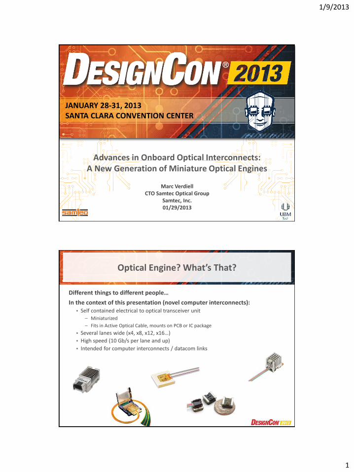
Optical Engine? What’s That?
Different things to different people…
In the context of this presentation (novel computer interconnects): Self contained electrical to optical transceiver unit
– Miniaturized
– Fits in Active Optical Cable, mounts on PCB or IC package
Several lanes wide (x4, x8, x12, x16…)
High speed (10 Gb/s per lane and up)
Intended for computer interconnects / datacom links
1/9/2013
2
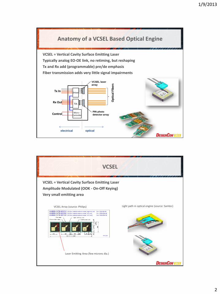
Anatomy of a VCSEL Based Optical Engine
VCSEL = Vertical Cavity Surface Emitting Laser
Typically analog EO-OE link, no retiming, but reshaping
Tx and Rx add (programmable) pre/de emphasis
Fiber transmission adds very little signal impairments
Driver
TIA
Micro – Controller
Tx In
Rx Out Op
tica
l Fib
ers
Control
optical electrical
VCSEL laser
array
PIN photo
detector array
VCSEL
VCSEL = Vertical Cavity Surface Emitting Laser
Amplitude Modulated (OOK - On-Off Keying)
Very small emitting area
Laser Emitting Area (few microns dia.)
VCSEL Array (source: Philips) Light path in optical engine (source: Samtec)
1/9/2013
3
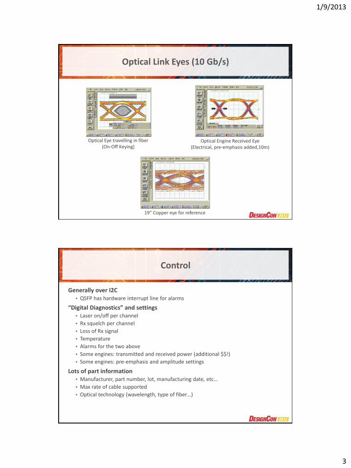
Optical Link Eyes (10 Gb/s)
Optical Eye travelling in fiber (On-Off Keying)
Optical Engine Received Eye (Electrical, pre-emphasis added,10m)
19” Copper eye for reference
Control
Generally over I2C QSFP has hardware interrupt line for alarms
“Digital Diagnostics” and settings Laser on/off per channel
Rx squelch per channel
Loss of Rx signal
Temperature
Alarms for the two above
Some engines: transmitted and received power (additional $$!)
Some engines: pre-emphasis and amplitude settings
Lots of part information Manufacturer, part number, lot, manufacturing date, etc…
Max rate of cable supported
Optical technology (wavelength, type of fiber…)
1/9/2013
4
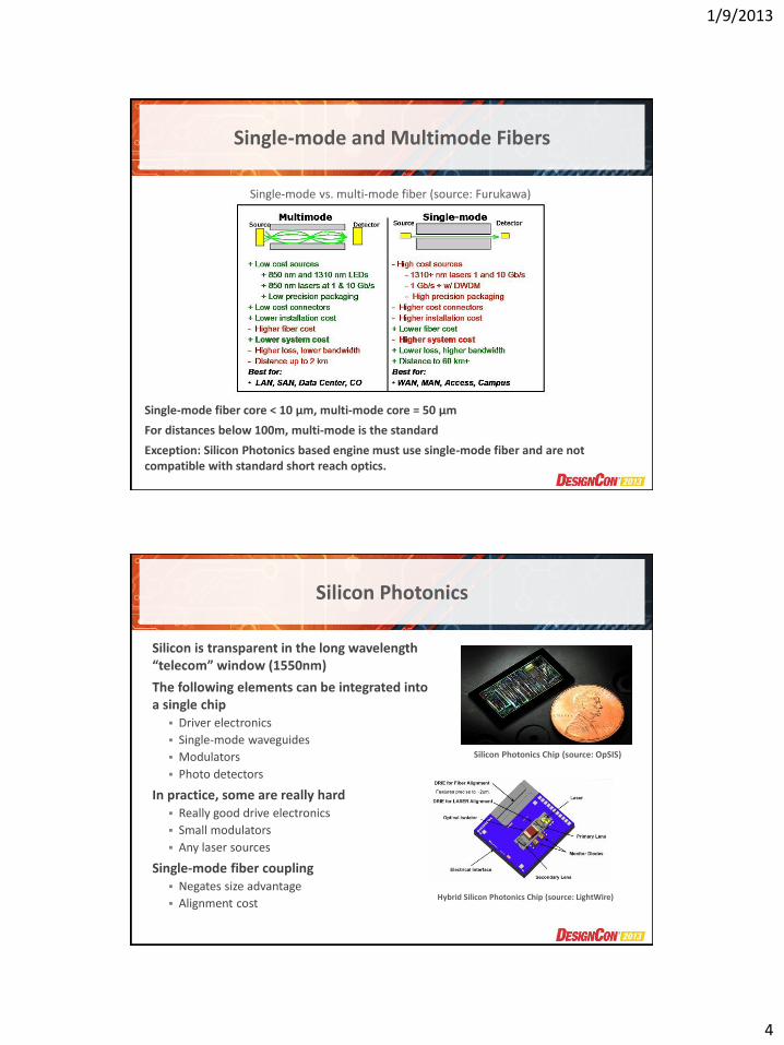
Single-mode and Multimode Fibers
Single-mode fiber core < 10 µm, multi-mode core = 50 µm
For distances below 100m, multi-mode is the standard
Exception: Silicon Photonics based engine must use single-mode fiber and are not compatible with standard short reach optics.
Single-mode vs. multi-mode fiber (source: Furukawa)
Silicon Photonics
Silicon is transparent in the long wavelength “telecom” window (1550nm)
The following elements can be integrated into a single chip
Driver electronics
Single-mode waveguides
Modulators
Photo detectors
In practice, some are really hard Really good drive electronics
Small modulators
Any laser sources
Single-mode fiber coupling Negates size advantage
Alignment cost
Silicon Photonics Chip (source: OpSIS)
Hybrid Silicon Photonics Chip (source: LightWire)
1/9/2013
5
Continuous Technology Progress
Integrated Photonics Silicon Photonics (e.g. Luxtera)
– Good for high level of complexity / integration
– Single-mode / long wavelength
In Photonic integrated circuits (e.g. Infinera)
– High end telecom single-mode / long wavelength / WDM/ long distance
VCSEL based technology Optical micro molding
– Intel Lightpeak (consumer)
– Micro-engines (Avago, Samtec)
Multi-mode / short wavelength / parallel / short distance
Interoperable with standard short reach
Micro-connector systems Specially adapted for miniature optics
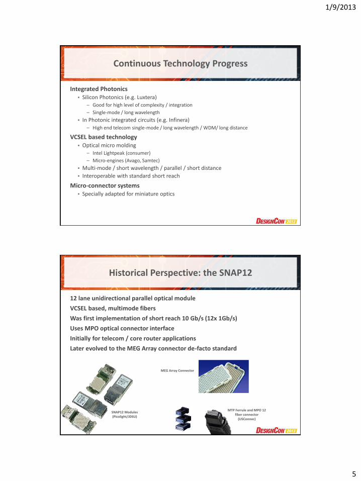
Historical Perspective: the SNAP12
12 lane unidirectional parallel optical module
VCSEL based, multimode fibers
Was first implementation of short reach 10 Gb/s (12x 1Gb/s)
Uses MPO optical connector interface
Initially for telecom / core router applications
Later evolved to the MEG Array connector de-facto standard
SNAP12 Modules (Picolight/JDSU)
MEG Array Connector
MTP Ferrule and MPO 12 fiber connector
(USConnec)
1/9/2013
6
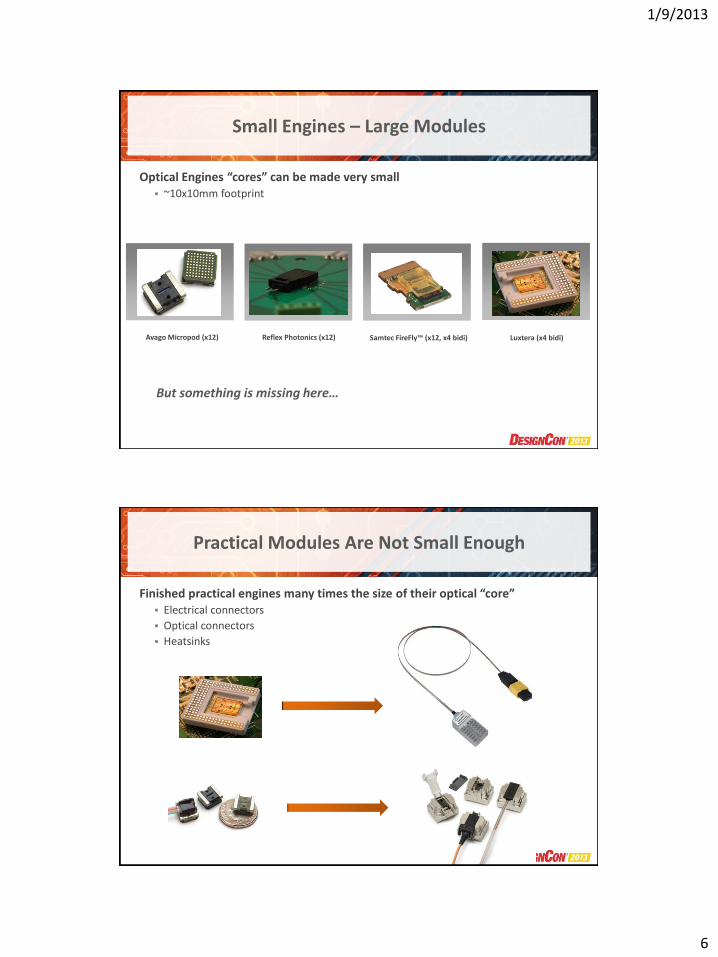
Small Engines – Large Modules
Optical Engines “cores” can be made very small ~10x10mm footprint
Avago Micropod (x12) Reflex Photonics (x12) Samtec FireFly™ (x12, x4 bidi) Luxtera (x4 bidi)
But something is missing here…
Practical Modules Are Not Small Enough
Finished practical engines many times the size of their optical “core” Electrical connectors
Optical connectors
Heatsinks
1/9/2013
7
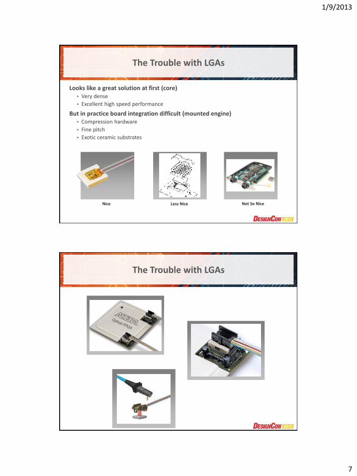
The Trouble with LGAs
Looks like a great solution at first (core) Very dense
Excellent high speed performance
But in practice board integration difficult (mounted engine) Compression hardware
Fine pitch
Exotic ceramic substrates
Nice Less Nice Not So Nice
The Trouble with LGAs
1/9/2013
8
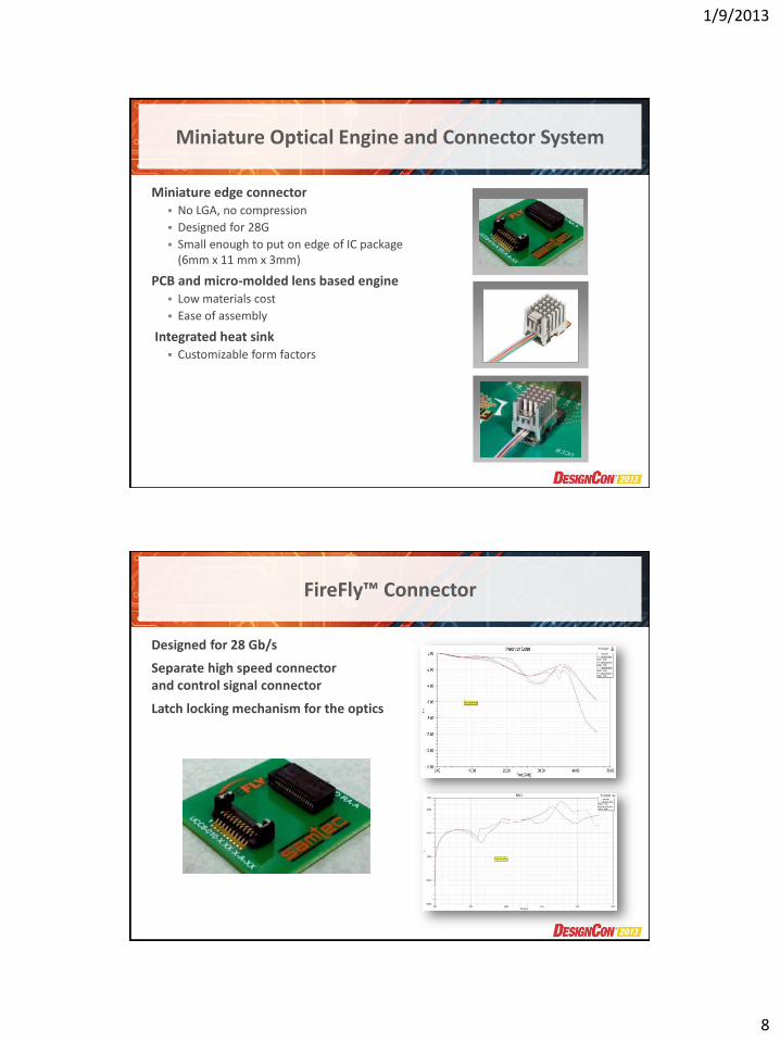
Miniature Optical Engine and Connector System
Miniature edge connector No LGA, no compression
Designed for 28G
Small enough to put on edge of IC package (6mm x 11 mm x 3mm)
PCB and micro-molded lens based engine Low materials cost
Ease of assembly
Integrated heat sink Customizable form factors
FireFly™ Connector
Designed for 28 Gb/s
Separate high speed connector and control signal connector
Latch locking mechanism for the optics
1/9/2013
9
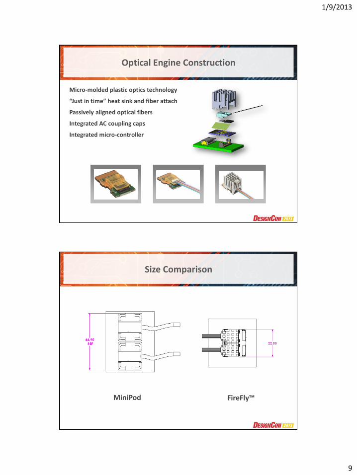
Optical Engine Construction
Micro-molded plastic optics technology
“Just in time” heat sink and fiber attach
Passively aligned optical fibers
Integrated AC coupling caps
Integrated micro-controller
Size Comparison
MiniPod FireFly™
1/9/2013
10
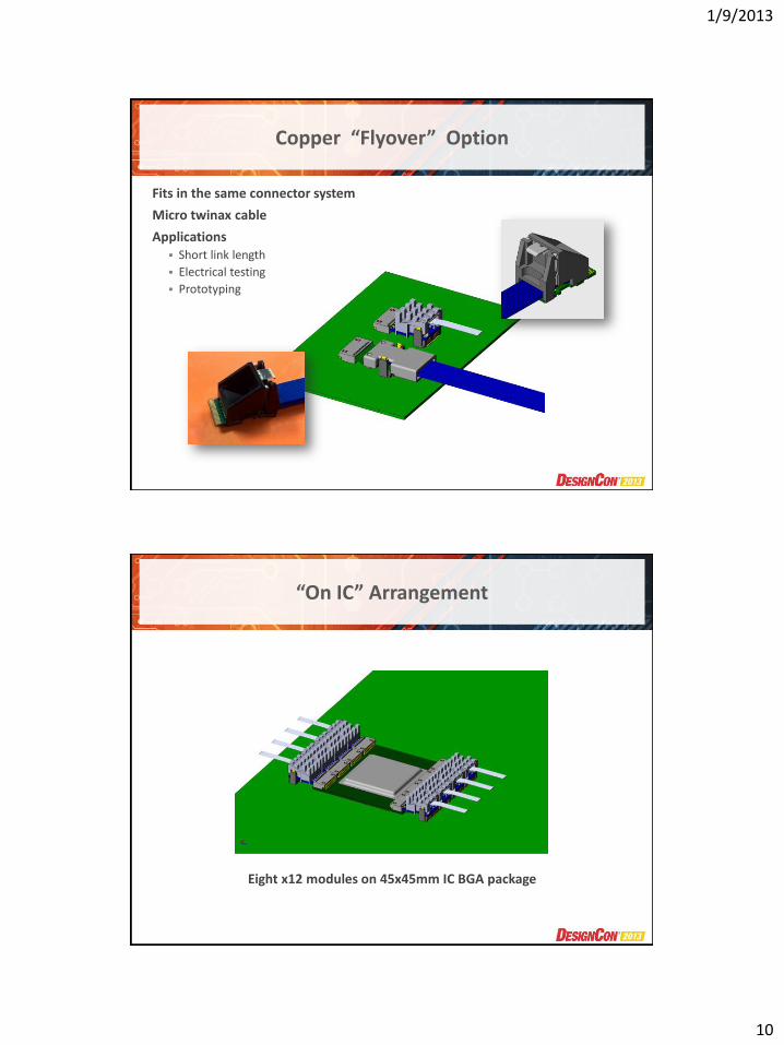
Copper “Flyover” Option
Fits in the same connector system
Micro twinax cable
Applications Short link length
Electrical testing
Prototyping
“On IC” Arrangement
Eight x12 modules on 45x45mm IC BGA package
1/9/2013
11
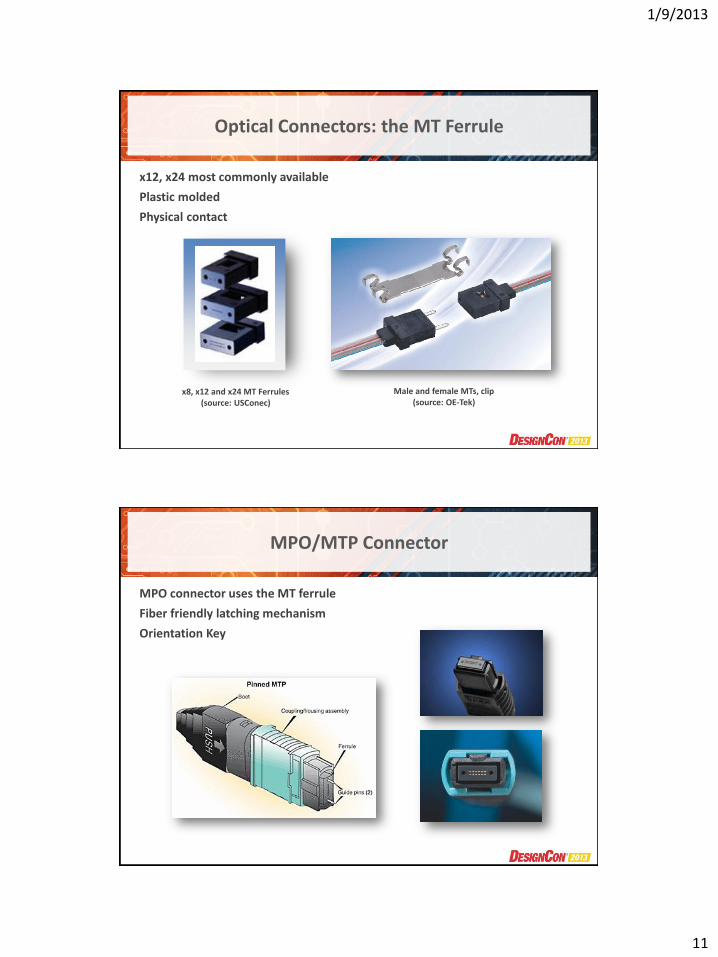
Optical Connectors: the MT Ferrule
x12, x24 most commonly available
Plastic molded
Physical contact
x8, x12 and x24 MT Ferrules (source: USConec)
Male and female MTs, clip (source: OE-Tek)
MPO/MTP Connector
MPO connector uses the MT ferrule
Fiber friendly latching mechanism
Orientation Key
1/9/2013
12
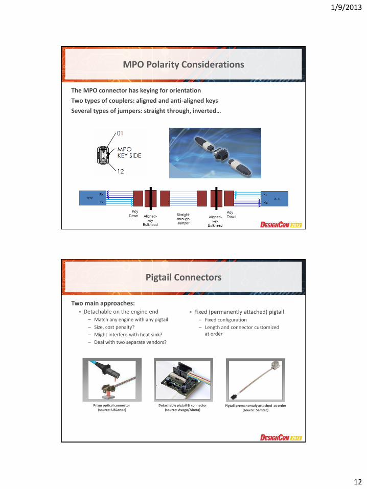
MPO Polarity Considerations
The MPO connector has keying for orientation
Two types of couplers: aligned and anti-aligned keys
Several types of jumpers: straight through, inverted…
Pigtail Connectors
Two main approaches: Detachable on the engine end
– Match any engine with any pigtail
– Size, cost penalty?
– Might interfere with heat sink?
– Deal with two separate vendors?
Prizm optical connector (source: USConec)
Detachable pigtail & connector (source: Avago/Altera)
Pigtail premanentaly attached at order (source: Samtec)
Fixed (permanently attached) pigtail
– Fixed configuration
– Length and connector customized at order
1/9/2013
13
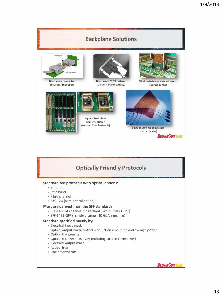
Backplane Solutions
Blind mate connector (source: Amphenol)
Blind mate MPO system (source: TE Connectivity)
Optical backplane implementation
(source: Elma Bustronic) Fiber shuffle on flex circuit
(source: Molex)
Blind mate transceiver connector (source: Samtec)
Optically Friendly Protocols
Standardized protocols with optical options: Ethernet Infiniband Fibre channel SAS 12G (with optical option)
Most are derived from the SFF standards SFF-8436 (4 channel, bidirectional, 4x 10Gb/s QSFP+) SFF-8431 (SFP+, single channel, 10 Gb/s signaling)
Standard specified mostly by: Electrical input mask Optical output mask, optical modulation amplitude and average power Optical link penalty Optical receiver sensitivity (including stressed sensitivity) Electrical output mask Added jitter Link bit error rate
1/9/2013
14
SFF/Standard Based Engines
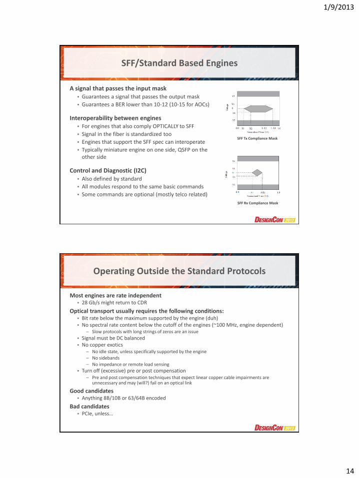
A signal that passes the input mask Guarantees a signal that passes the output mask
Guarantees a BER lower than 10-12 (10-15 for AOCs)
Interoperability between engines For engines that also comply OPTICALLY to SFF
Signal in the fiber is standardized too
Engines that support the SFF spec can interoperate
Typically miniature engine on one side, QSFP on the other side
Control and Diagnostic (I2C) Also defined by standard
All modules respond to the same basic commands
Some commands are optional (mostly telco related)
SFF Tx Compliance Mask
SFF Rx Compliance Mask
Operating Outside the Standard Protocols
Most engines are rate independent 28 Gb/s might return to CDR
Optical transport usually requires the following conditions: Bit rate below the maximum supported by the engine (duh) No spectral rate content below the cutoff of the engines (~100 MHz, engine dependent)
– Slow protocols with long strings of zeros are an issue
Signal must be DC balanced No copper exotics
– No idle state, unless specifically supported by the engine
– No sidebands
– No impedance or remote load sensing
Turn off (excessive) pre or post compensation – Pre and post compensation techniques that expect linear copper cable impairments are
unnecessary and may (will?) fail on an optical link
Good candidates Anything 8B/10B or 63/64B encoded
Bad candidates PCIe, unless…
1/9/2013
15
PCIe Specific Support
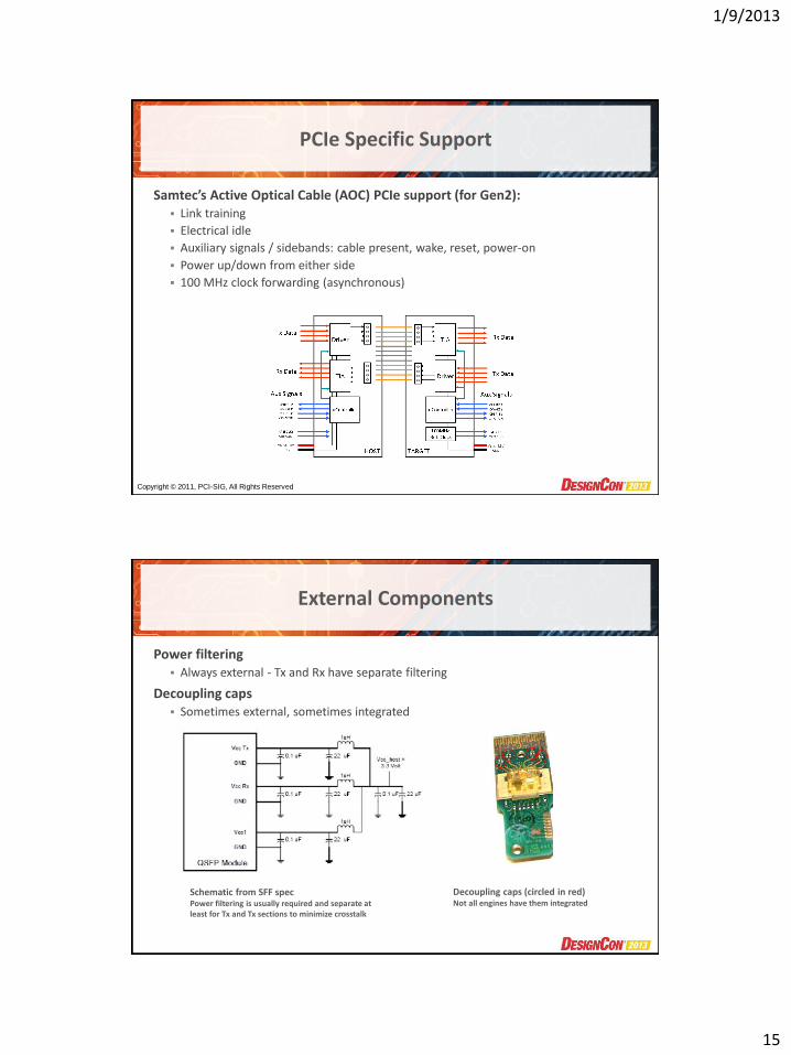
Samtec’s Active Optical Cable (AOC) PCIe support (for Gen2): Link training
Electrical idle
Auxiliary signals / sidebands: cable present, wake, reset, power-on
Power up/down from either side
100 MHz clock forwarding (asynchronous)
Copyright © 2011, PCI-SIG, All Rights Reserved
External Components
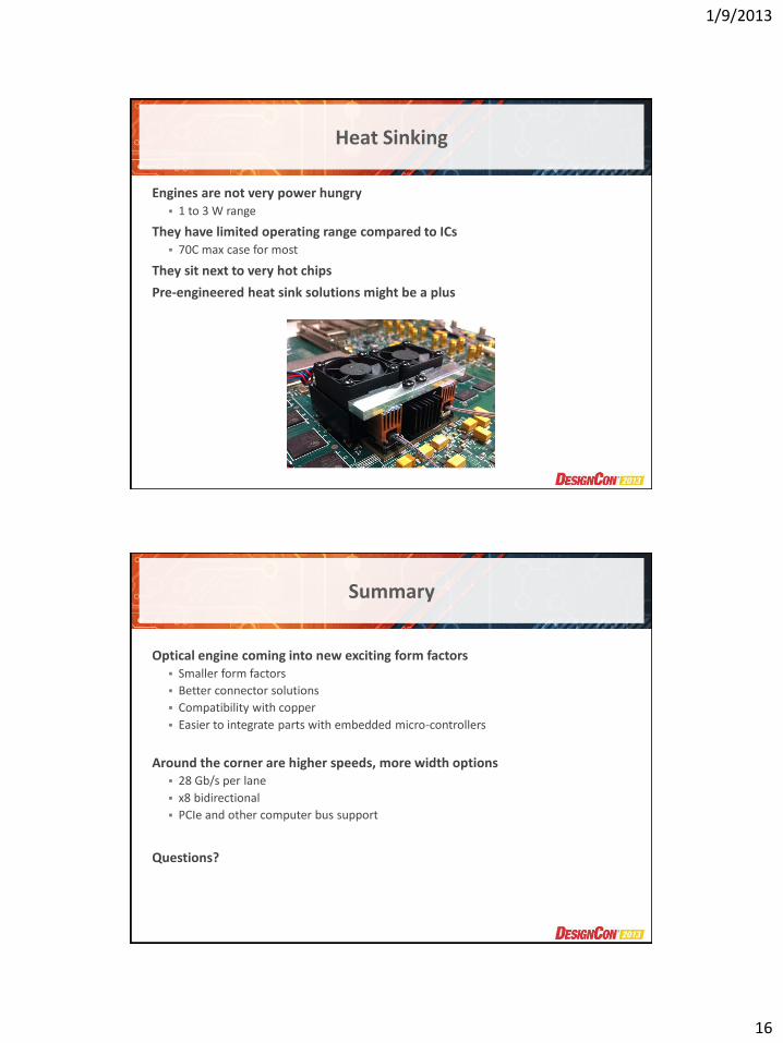
Power filtering Always external - Tx and Rx have separate filtering
Decoupling caps Sometimes external, sometimes integrated
Schematic from SFF spec Power filtering is usually required and separate at least for Tx and Tx sections to minimize crosstalk
Decoupling caps (circled in red) Not all engines have them integrated
1/9/2013
16
Heat Sinking
Engines are not very power hungry 1 to 3 W range
They have limited operating range compared to ICs 70C max case for most
They sit next to very hot chips
Pre-engineered heat sink solutions might be a plus
Summary
Optical engine coming into new exciting form factors Smaller form factors
Better connector solutions
Compatibility with copper
Easier to integrate parts with embedded micro-controllers
Around the corner are higher speeds, more width options 28 Gb/s per lane
x8 bidirectional
PCIe and other computer bus support
Questions?
1/9/2013
17
JANUARY 28-31, 2013 SANTA CLARA CONVENTION CENTER
Advances in Onboard Optical Interconnects: A New Generation of Miniature Optical Engines
Marc Verdiell CTO Samtec Optical Group
Samtec, Inc. 01/29/2013