Embed Size (px)
Citation preview

Optical embedded dust sensor for engine protection and early warning on M1 Abrams/ground combat vehicles
Hai Lina, Gregor A. Waldherrb, Timothy Burch*a aIntelligent Optical Systems, 73 N. Vinedo Ave., Pasadena, CA, USA 91107-3759
bHal Technology, LLC, 7970 Cherry Avenue, Suite 303, Fontana, CA, USA 92336-4025 Disclaimer: Reference herein to any specific commercial company, product, process, or service by trade name, trademark, manufacturer, or otherwise, does not necessarily constitute or imply its endorsement, recommendation, or favoring by the United States Government or the Department of the Army (DoA). The opinions of the authors expressed herein do not necessarily state or reflect those of the United States Government or the DoA, and shall not be used for advertising or product endorsement purposes.
ABSTRACT
The Dual Optical Embedded Dust Sensor (DOEDS) is designed for the sensitive, accurate detection of particles for preventive health monitoring of the AGT1500 engine and M1 Abrams/Ground Combat Vehicles (GCVs). DOEDS is a real-time sensor that uses an innovative combination of optical particle sensing technologies and mechanical packaging in a rugged, compact and non-intrusive optical design. The optical sensor, implementing both a single particle sensor and a mass sensor, can operate in harsh environments (up to 400°F) to meet the particle size, size distribution, mass concentration, and response time criteria. The sensor may be flush- or inline-mounted in multiple engine locations and environments.
Keywords: particle concentration, particle size, zero count, turbine blade erosion, air filter efficiency, dust leak
1. INTRODUCTION Military turbine engines with large intake air flow rates such as the AGT1500 deployed on the M1 Abrams, and proposed for Ground Combat Vehicles (GCVs) and helicopter engines,1 are continually exposed to dust and particle contamination when operated in desert environments for extended periods. Such exposure leads to premature blade wear, increased maintenance time, failure of engine components, and costly engine damage.
What is needed is a low-cost, embedded dust detector (EDD) that can be integrated into the engine to provide an early warning of seal leakage or deterioration of air filters, thereby reducing engine damage and improving vehicle operational readiness. To be effective, the EDD must be placed downstream from all potential dust leak sources, which may include: (1) low efficiency barrier filters; (2) dust falling into the clean air plenum during barrier filter removal; (3) seal failures in the plenum box; and (4) an improperly installed inlet plenum seal ring connecting the air cleaner box to the turbine bell mouth inlet.
At this time, no commercial off-the-shelf (COTS) dust sensors are in use by the military because of the special design requirements for operation and performance in the harsh desert environment. Previous research2,3 has not led to a reliable dust detector, but has established design parameters such as the detectable particle size range (from 200 μm down to 5 μm, and possibly 1 μm), the detector response (within 5 to 50 seconds), and operation in a range of air flows (500 to 10,000 scfm for the M1 Abrams). Incidentally, that previous research used optical particle counters to corroborate their dust detector operation.
In a trade study performed by Intelligent Optical Systems (IOS) of several sensor technologies for dust detection, optical scattering sensing emerged as one of the most promising methodologies, due to its fast response time (microseconds), non-invasive nature, sensitivity (single particle), and applicability to field use. This technique detects optical pulsed signals scattering from dust particles whose amplitudes are proportional to the size of the particles, while the number of
*[email protected]; phone 1 626 768 2568; fax 1 626 782 6177; www.intopsys.com
UNCLASSIFIED: Distribution Statement A. Approved for public release.

Report Documentation Page Form ApprovedOMB No. 0704-0188
Public reporting burden for the collection of information is estimated to average 1 hour per response, including the time for reviewing instructions, searching existing data sources, gathering andmaintaining the data needed, and completing and reviewing the collection of information. Send comments regarding this burden estimate or any other aspect of this collection of information,including suggestions for reducing this burden, to Washington Headquarters Services, Directorate for Information Operations and Reports, 1215 Jefferson Davis Highway, Suite 1204, ArlingtonVA 22202-4302. Respondents should be aware that notwithstanding any other provision of law, no person shall be subject to a penalty for failing to comply with a collection of information if itdoes not display a currently valid OMB control number.
1. REPORT DATE 11 APR 2012
2. REPORT TYPE Journal Article
3. DATES COVERED 11-04-2012 to 11-04-2012
4. TITLE AND SUBTITLE OPTICAL EMBEDDED DUST SENSOR FOR M1 ABRAMSENGINE PROTECTION
5a. CONTRACT NUMBER W56HZV-11-C-0320
5b. GRANT NUMBER
5c. PROGRAM ELEMENT NUMBER
6. AUTHOR(S) Hai Lin; Gregor Waldherr; Timothy Burch
5d. PROJECT NUMBER
5e. TASK NUMBER
5f. WORK UNIT NUMBER
7. PERFORMING ORGANIZATION NAME(S) AND ADDRESS(ES) Intelligent Optical Systems,73 N. Vinedo Ave.,Pasadena,CA,91107-3759
8. PERFORMING ORGANIZATION REPORT NUMBER ; #22730
9. SPONSORING/MONITORING AGENCY NAME(S) AND ADDRESS(ES) U.S. Army TARDEC, 6501 E.11 Mile Rd, Warren, MI, 48397-5000
10. SPONSOR/MONITOR’S ACRONYM(S) TARDEC
11. SPONSOR/MONITOR’S REPORT NUMBER(S) #22730
12. DISTRIBUTION/AVAILABILITY STATEMENT Approved for public release; distribution unlimited
13. SUPPLEMENTARY NOTES
14. ABSTRACT The Dual Optical Embedded Dust Sensor (DOEDS) is designed for the sensitive, accurate detection ofparticles for preventive health monitoring of the AGT1500 engine and M1 Abrams/Ground CombatVehicles (GCVs). DOEDS is a real-time sensor that uses an innovative combination of optical particlesensing technologies and mechanical packaging in a rugged, compact and non-intrusive optical design. Theoptical sensor, implementing both a single particle sensor and a mass sensor, can operate in harshenvironments (up to 400?F) to meet the particle size, size distribution, mass concentration, and responsetime criteria. The sensor may be flush- or inline-mounted in multiple engine locations and environments.
15. SUBJECT TERMS particle concentration, particle size, zero count, turbine blade erosion, air filter efficiency, dust leak
16. SECURITY CLASSIFICATION OF: 17. LIMITATIONOF ABSTRACT
Same asReport (SAR)
18. NUMBEROF PAGES
12
19a. NAME OFRESPONSIBLE PERSON
a. REPORT unclassified
b. ABSTRACT unclassified
c. THIS PAGE unclassified
Standard Form 298 (Rev. 8-98) Prescribed by ANSI Std Z39-18

particle pulses is proportional to the concentration of particles. Optical scattering sensing can easily measure and quantify dust/particle size distributions to identify root causes of failure modes for a comprehensive early warning and health management solution.
To address the need for an effective dust detector for the AGT1500 engine and M1 Abrams/GCVs, IOS is designing a Dual Optical Embedded Dust Sensor (DOEDS, patent pending), a real-time optical sensor for dust intrusion monitoring that combines proven optical particle sensing technologies with mechanical packaging in a rugged, compact, and non-intrusive design. The optical sensor, implementing both a single particle sensor and a mass sensor, is designed to operate in harsh environments (up to 400°F) to meet the particle size, size distribution, mass concentration, and response time criteria. The wide flow rate range (up to 10,000 scfm) will allow the sensor to be flush- or inline-mounted at any viable location downstream from the V-Pac barrier filters to inside the engine compressor.
We have proven the feasibility of an optical dust sensor for real-time continuous monitoring, and its effectiveness in quantitatively measuring dust penetration in the AGT1500 engine. We experimentally demonstrated the capabilities of the DOEDS under laboratory conditions, defined the sensor mounting location, and developed the conceptual design of a prototype dual optical sensor/system for future testing. Although the studies to date have focused on the AGT1500, the sensor and design concept will be robust and extensible to other engines.
2. METHODOLOGY Optical instrumentation has been used to determine particle contamination in air and liquids in various industries for many years. In addition, the correlation between airborne particles and final product quality has long been recognized in the semiconductor, flat panel display, and hard disk storage manufacturing industries, where improvement of air quality (reduction of particulate contamination) has led to increases in final product yield. Different techniques are used to measure particle size and distribution, depending on the size of particles that are of interest. For particle matter measurements, direct light scattering instruments are used to cover the range of interest, with light scattering instruments being most relevant for mass concentration measurements.
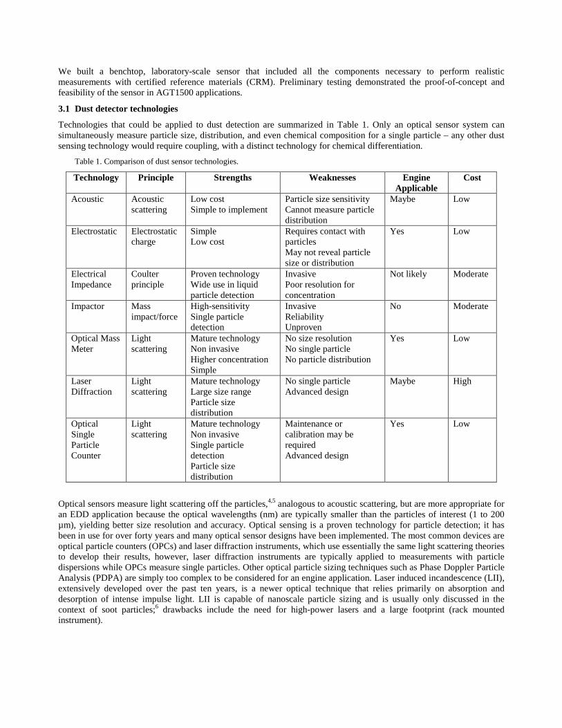
The main idea behind the DOEDS development is the light scattering principle (Figure 1). In general, the scattering measured from an arbitrarily-shaped particle is a complicated quantity and depends on the equivalent particle diameter, particle shape, material properties, and the efficiency and angle of detection. The scattered light intensity is proportional to the equivalent size of a particle and gives adequate measurement of particle sizes and size distributions with count electronics.4 The problem is displayed graphically in Figure 1 and can be written as
( )
022
2 ,,, Irk
mdsImeasϕθη= (1)
The measured intensity measI is related to the incident intensity 0I by the distance from the source r , the wavenumber
λπ /2=k , the collection efficiency η , and the scattering coefficient ( )ϕθ ,,,mds which depends on the effective particle diameter d , material refractive index m , and the scattering angles. Inverting the angularly varying scattering pattern from an individual particle would uniquely determine its shape, size, and complex refractive index if such an inversion were possible. In general, the particle size is classified as an equivalent diameter of a spheric particle, and has proven to be a very effective mean for statistical measurement of particle sizes, distributions, and concentrations.
As shown in Figure 2, calculations reveal that the scattering signal cross section is proportional to d6/λ4 in the Rayleigh region (d << λ), while the scattering signal cross section is proportional to d2 in the Mie region (d ~ λ) and d when d > λ.
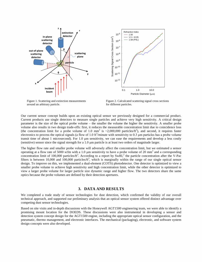
Figure 1. Scattering and extinction measurements around an arbitrary particle.
Figure 2. Calculcated scattering signal cross sections for different particles.
Our current sensor concept builds upon an existing optical sensor we previously designed for a commercial product. Current products use single detectors to measure single particles and achieve very high sensitivity. A critical design parameter is the size of the optical probe volume – the smaller the volume the higher the sensitivity. A smaller probe volume also results in two design trade-offs: first, it reduces the measurable concentration limit due to coincidence loss (the concentration limit for a probe volume of 1.0 mm3 is ~2,000,000 particles/ft3), and second, it requires faster electronics to process the optical signals (a flow of 1.0 ft3/minute with sensitivity to 0.3 μm particles has a probe volume transit time of about 1 microsecond). For 1.0 μm sensitivity, we can ease the requirements and develop a less costly (sensitive) sensor since the signal strength for a 1.0 μm particle is at least two orders of magnitude larger.
The higher flow rate and smaller probe volume will adversely affect the concentration limit, but we estimated a sensor operating at a flow rate of 5000 scfm with a 1.0 μm sensitivity to have a probe volume of 20 mm3 and a corresponding concentration limit of 100,000 particles/ft3. According to a report by SwRI,2 the particle concentration after the V-Pac filters is between 10,000 and 100,000 particles/ft3, which is marginally within the range of our single optical sensor design. To improve on this, we implemented a dual-element (COTS) photodetector. One detector is optimized to view a smaller probe volume to achieve high sensitivity and high concentration limit, while the other detector is optimized to view a larger probe volume for larger particle size dynamic range and higher flow. The two detectors share the same optics because the probe volumes are defined by their detection apertures.
3. DATA AND RESULTS We completed a trade study of sensor technologies for dust detection, which confirmed the validity of our overall technical approach, and supported our preliminary analysis that an optical sensor system offered distinct advantage over competing dust sensor technologies.
Based on site visits and in-depth discussions with the Honeywell AGT1500 engineering team, we were able to identify a promising mount location for the DOEDS. These discussions were also instrumental in developing a sensor and detection system concept design for the AGT1500 engine, including the appropriate optical sensor configuration, and the pneumatic, thermo management, and electronic interfaces. The mechanical (packaging), electronic, and software system design concepts were also developed.
particle
y
x
rz
θ
extinctiondetectorin-plane
scatteringdetector
out-of-planescatteringdetector
φ
scatteringplane
incidentbeam
0.1 1.0 10.0Particle Diameter (µm)
10-12
10-11
10-10
10-9
10-8
10-7
10-6
10-5
Sca
tterin
g S
igna
l Cro
ss S
ectio
n (c
m2 )
1.501.5 + i0.051.58 (PSL)
Refractive Index
We built a benchtop, laboratory-scale sensor that included all the components necessary to perform realistic measurements with certified reference materials (CRM). Preliminary testing demonstrated the proof-of-concept and feasibility of the sensor in AGT1500 applications.
3.1 Dust detector technologies
Technologies that could be applied to dust detection are summarized in Table 1. Only an optical sensor system can simultaneously measure particle size, distribution, and even chemical composition for a single particle – any other dust sensing technology would require coupling, with a distinct technology for chemical differentiation.
Table 1. Comparison of dust sensor technologies.
Technology Principle Strengths Weaknesses Engine Applicable
Cost
Acoustic Acoustic scattering
Low cost Simple to implement
Particle size sensitivity Cannot measure particle distribution
Maybe Low
Electrostatic Electrostatic charge
Simple Low cost
Requires contact with particles May not reveal particle size or distribution
Yes Low
Electrical Impedance
Coulter principle
Proven technology Wide use in liquid particle detection
Invasive Poor resolution for concentration
Not likely Moderate
Impactor Mass impact/force
High-sensitivity Single particle detection
Invasive Reliability Unproven
No Moderate
Optical Mass Meter
Light scattering
Mature technology Non invasive Higher concentration Simple
No size resolution No single particle No particle distribution
Yes Low
Laser Diffraction
Light scattering
Mature technology Large size range Particle size distribution
No single particle Advanced design
Maybe High
Optical Single Particle Counter
Light scattering
Mature technology Non invasive Single particle detection Particle size distribution
Maintenance or calibration may be required Advanced design
Yes Low
Optical sensors measure light scattering off the particles,4,5 analogous to acoustic scattering, but are more appropriate for an EDD application because the optical wavelengths (nm) are typically smaller than the particles of interest (1 to 200 µm), yielding better size resolution and accuracy. Optical sensing is a proven technology for particle detection; it has been in use for over forty years and many optical sensor designs have been implemented. The most common devices are optical particle counters (OPCs) and laser diffraction instruments, which use essentially the same light scattering theories to develop their results, however, laser diffraction instruments are typically applied to measurements with particle dispersions while OPCs measure single particles. Other optical particle sizing techniques such as Phase Doppler Particle Analysis (PDPA) are simply too complex to be considered for an engine application. Laser induced incandescence (LII), extensively developed over the past ten years, is a newer optical technique that relies primarily on absorption and desorption of intense impulse light. LII is capable of nanoscale particle sizing and is usually only discussed in the context of soot particles;6 drawbacks include the need for high-power lasers and a large footprint (rack mounted instrument).
To meet the requirements for an embedded dust detector for M1 Abrams/GCVs, our sensor approach implemented a dual optical detector arrangement that combines an optical mass meter and an optical particle counter in a single compact, rugged design. The optical mass sensor measures clusters of particles with sizes greater than a few microns, and the optical particle sensor measures individual particles with high sensitivity (single particles <0.3 µm is possible), yielding size distributions over a wide range.
3.2 Determining dust sensor mount location
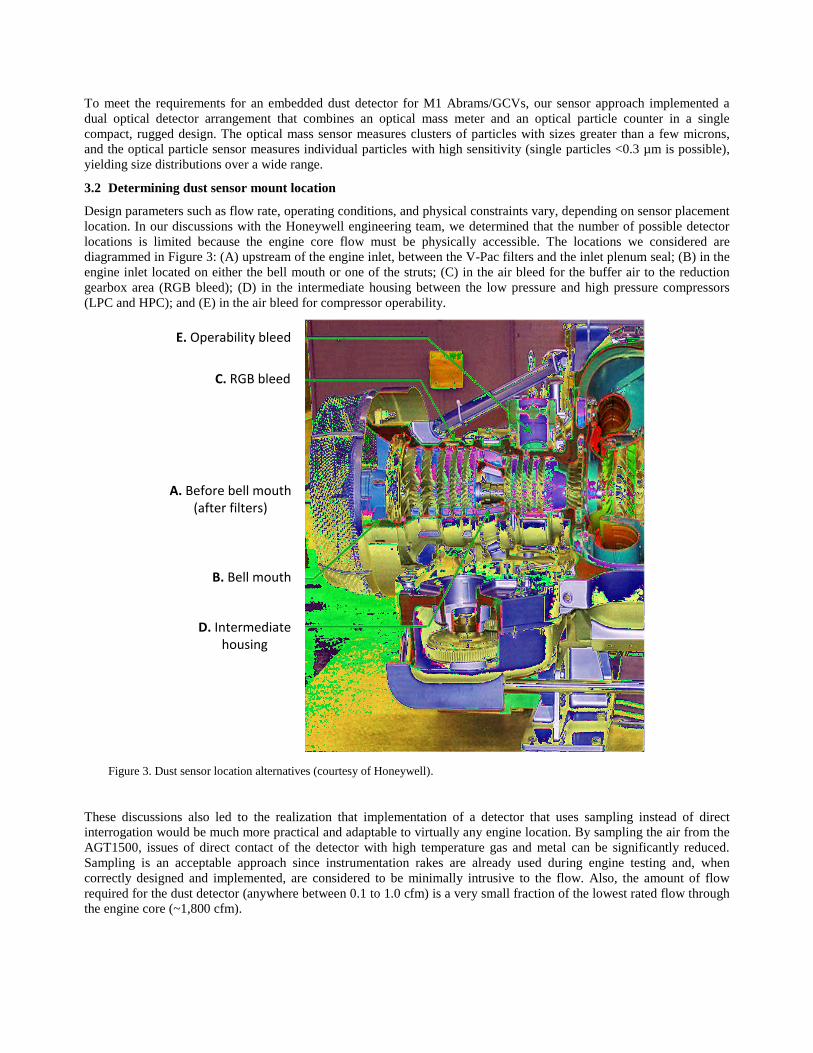
Design parameters such as flow rate, operating conditions, and physical constraints vary, depending on sensor placement location. In our discussions with the Honeywell engineering team, we determined that the number of possible detector locations is limited because the engine core flow must be physically accessible. The locations we considered are diagrammed in Figure 3: (A) upstream of the engine inlet, between the V-Pac filters and the inlet plenum seal; (B) in the engine inlet located on either the bell mouth or one of the struts; (C) in the air bleed for the buffer air to the reduction gearbox area (RGB bleed); (D) in the intermediate housing between the low pressure and high pressure compressors (LPC and HPC); and (E) in the air bleed for compressor operability.
Figure 3. Dust sensor location alternatives (courtesy of Honeywell).
These discussions also led to the realization that implementation of a detector that uses sampling instead of direct interrogation would be much more practical and adaptable to virtually any engine location. By sampling the air from the AGT1500, issues of direct contact of the detector with high temperature gas and metal can be significantly reduced. Sampling is an acceptable approach since instrumentation rakes are already used during engine testing and, when correctly designed and implemented, are considered to be minimally intrusive to the flow. Also, the amount of flow required for the dust detector (anywhere between 0.1 to 1.0 cfm) is a very small fraction of the lowest rated flow through the engine core (~1,800 cfm).
E. Operability bleed
C. RGB bleed
A. Before bell mouth (after filters)
B. Bell mouth
D. Intermediate housing

The two primary sources of dust ingestion are either the filters or the inlet plenum seal. Of these, circumvention of the plenum seal was determined to be the most significant, since improper seating of the seal cannot be verified until after the engine has been removed for service and the damage has already occurred. Filter problems such as a large penetration, poor filter sealing, or just poor performance are less significant because the filters can be visually inspected, and the problems develop more slowly.
Conditions such as temperature, flow velocity, flow uniformity, and accessibility will affect the quality of the dust detection, and the flow disturbance by the dust detector could adversely affect gas turbine operation. These qualities, summarized in Table 2, were assessed for each of the potential dust detector locations.
Table 2. Summary of qualities for dust sensor location alternatives for engine protection. Dust Detector Location A B C D E
Maximum temperature (°F) for 87°F ambient 87 87 252 357 500
Estimated maximum mass flow rate (lb/s) 10.5 10.5 0.12 10.5 1.0
Estimated maximum velocity 30 150 70 150 50
Air flow under all operating conditions? yes yes yes yes no
Tolerance to flow disturbance? yes somewhat yes no yes
Spatial variation of dust particles low high low low low
Dust distribution as in engine core flow? maybe maybe ?? yes ??
All possible dust sources included? no yes yes yes yes
Priority of the location alternatives 4/5 3 2 1 4/5
A simulation analysis of particle distribution through various engine compressor stages revealed that the root cause of particle penetration to the engine may be identified by changes in particle size distributions, which are capable of being measured by dual optical sensors. Other techniques cannot measure size distribution and therefore cannot be used to determine the root cause of failure. The DOEDS technology can also be used for quality assurance of filter testing and installation during engine manufacturing and service.
We determined that the most likely implementation of the engine dust detector is an optical sensor coupled with an instrumentation rake for sampling the engine core flow from the instrumentation port(s) already present in the intermediate housing (D), shown in Figure 4. Situating the dust detector in the intermediate housing ensures that core flow dust characteristics will be measured. The dust will have been uniformly distributed by prior interaction with the low pressure compressor blades. The flow disturbance issues at (D) can be minimized, especially with guidance from Honeywell, and the only significant issue remaining is thermal management.
Figure 4. Two instrumentation ports in the intermediate housing may be the best choice for the dust sensor locations (courtesy of Honeywell).

3.3 Sensor and system design concept
As previously mentioned, the best location for a single dust sensor was determined to be in the intermediate housing. An overview of the sensor concept is shown in Figure 5. The sensor consists of a sampling head that is inserted into the instrumentation pad on the intermediate housing of the AGT1500. The sampling head is connected to a sensor body, which would most likely be located near the EMU and timer module. Separation of the sampling head and sensor body allows easy adaptation of the sensor concept to different sensor locations since each component can be independently designed to meet the performance requirements.
Figure 5. Overview of sensor concept and its location relative to the AGT1500 gas turbine.
In developing the sensor and system design concept and specifications, aspects such as flow control, sampling head, enclosure design, and thermal management were investigated.
Flow Control: The air flow through the sensor is best controlled passively (i.e., a venturi) to avoid the dust intrusion problems associated with an active flow control (i.e., a valve). A passive flow control can be designed such that particles would minimally disturb its performance with the actual flow rate varying over the range of engine operating conditions. A venturi is an ideal flow control since the sloping entrance and exit to a venturi virtually eliminates the potential for particle accumulation around the flow control. By concurrently measuring temperature and pressure drop across the venturi, the sensor flow can also be determined. The best option for reduced sensor flow variability seems to be exhausting the sensor flow into the atmosphere and placing the flow control downstream of the sensor. Not only does this offer the lowest flow variability, the flow is maintained near the current 0.1 cfm design point for the proven miniature optical sensor (Hal Technologies, LLC (HalTech)) used in these studies. The flow variability does not significantly alter the data acquisition process. In the HalTech sensor, the particles passing the sensor are sampled for a given period of time and an integrated output is given. With flow variability, this integrated output simply needs to be corrected by the integrated flow past the sensor.
Sampling Head: The head consists of a mounting plate that is secured to the instrumentation pad, an insert that fits within the instrumentation pad slot, an optional sampling tube, and an interface for the connecting tube to the sensor body. The sampling head can be used with or without a sampling tube inserted into the AGT1500 side of the sampling head. A sampling path goes through the interior of the sampling head. This path’s design is dependent on whether flow control is implemented before or after the sensor. If flow control is implemented before the sensor, the venturi can be integrated into the sampling head. If flow control is after the sensor, the flow through the sampling head should be
(not to scale)Connecting tube
Sampling head
Instrumentation pad
Bell mouthGas turbine
Sensor enclosure
Electrical
Exhaust
relatively unimpeded. Since the sampling tube can be made separately from the rest of the sampling head, the size and shape of the tube and its entrance contour can be independently adjusted before welding the sampling tube into place.
Sensor Enclosure: The most significant concern of the dust sensor is the thermal packaging – it must be able to tolerate the high temperatures encountered in a gas turbine engine. The HalTech sensor body would be modified with a larger diameter air passage to retain the laminar flow condition at elevated temperatures, and the air passage could be lined with a quartz tube to isolate the flow physically from the sensor body components, and thermally insulate the sensor body (quartz is a poor thermal conductor).
Thermal Management: When measuring the dust intrusion in the intermediate housing, the sensor body would most likely be located in the vicinity of the timer module and EMU. The laser and electronic components of the sensor body must therefore meet the environmental test conditions applicable to the timer module and EMU. Per Honeywell, three items define the thermal environment around the sensor enclosure: (1) the timer module has a 130°F specification for ambient operating temperature; (2) measured air temperature in the vicinity of the timer module is ~300°F (Lycoming data); and (3) the maximum temperature of the sampling air flow through the sensor enclosure is 374°F. The resulting design temperature for the sensor enclosure components would thus lie somewhere between 130°F and 300°F. If additional sensors were to be located upstream of the bell mouth, the sensor would encounter ambient environmental conditions which are specified as -40°F to 130°F. Thermal management will require the interior of the sensor enclosure to remain below the design temperature. The sources of heat for the interior of the casing are the sampling air flow through the casing (max. 374°F at 1.0 cfm), the environment external to the casing (max. 300°F), and excess heat from the electronics and sensor. The heat transferred into the enclosure by the sampling air flow can be significantly reduced by insulating the tubing as it passes through the enclosure. The heat transferred into the enclosure from the external environment can be reduced by insulating the interior walls of the enclosure. Finally, the excess heat from the electronics and sensor can be controlled by efficient electronic design.
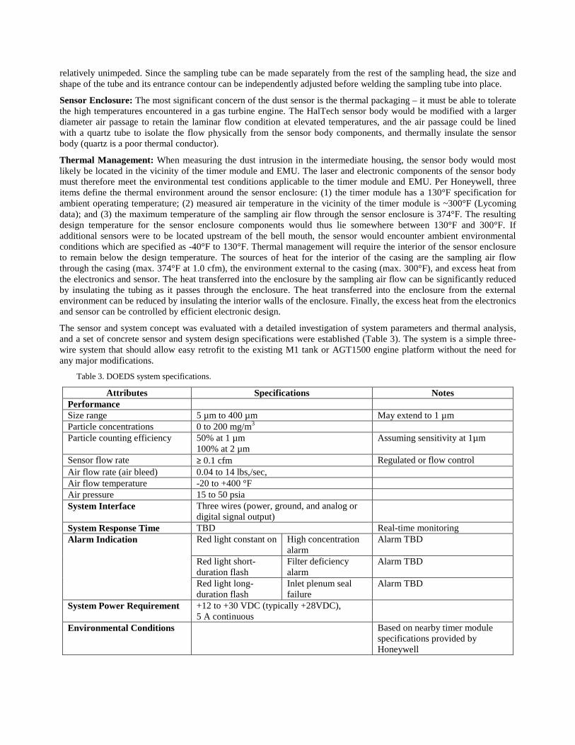
The sensor and system concept was evaluated with a detailed investigation of system parameters and thermal analysis, and a set of concrete sensor and system design specifications were established (Table 3). The system is a simple three-wire system that should allow easy retrofit to the existing M1 tank or AGT1500 engine platform without the need for any major modifications.
Table 3. DOEDS system specifications.
Attributes Specifications Notes Performance Size range 5 µm to 400 µm May extend to 1 µm Particle concentrations 0 to 200 mg/m3 Particle counting efficiency 50% at 1 µm
100% at 2 µm Assuming sensitivity at 1µm
Sensor flow rate ≥ 0.1 cfm Regulated or flow control Air flow rate (air bleed) 0.04 to 14 lbs,/sec, Air flow temperature -20 to +400 °F Air pressure 15 to 50 psia System Interface Three wires (power, ground, and analog or
digital signal output)
System Response Time TBD Real-time monitoring Alarm Indication Red light constant on High concentration
alarm Alarm TBD
Red light short-duration flash
Filter deficiency alarm
Alarm TBD
Red light long-duration flash
Inlet plenum seal failure
Alarm TBD
System Power Requirement +12 to +30 VDC (typically +28VDC), 5 A continuous
Environmental Conditions Based on nearby timer module specifications provided by Honeywell

Ambient operating temperature -40 to +130 °F Ambient storage temperature -40 to +130 °F Humidity 0 to 94% at up to 149°F for up to 48 hours Chemicals Vapor and contact to fuel/ hydraulic cleaning Steam and water with cleaning
agents Submergence 6 ft. for up to 30 min. Basic shock 30 g at 11 ms (half sine) Gun fire shock 55 g at 2.5 ms (half sine) Operational ballistic shock 75 g at 0.5 ms (half sine) High intensity shock 200 to 560 g at 0.5 ms Vibration 4 g sine to 500 Hz at 180 min. per axis Dimension 6 x 6 x 4 in. (estimated) Weight <5 lbs. Compliance EMI and compatibility per MIL-STD-416 Reliability TBD
3.4 Sensor development
Although a single optical sensor such as the miniature sensor developed by HalTech is able to detect particles smaller than 1.0 µm, a dual optical embedded dust sensor (DOEDS) is necessary to meet the specifications of large dynamic ranges of particle sizes and concentrations. The DOEDS design concept is illustrated in Figure 6.
Figure 6. Dual optical embedded dust sensor (DOEDS) design concept.
As illustrated in Figure 6, the first detector (D1) would image or view a smaller sensing zone and achieve maximum sensitivity of particle sizes. A smaller sensing volume would result in measurement of a smaller particle concentration range. By implementing a second detector (D2) that views a larger sensing zone and collects less scattering signal, the result would be less sensitivity of particle sizes with an increased measurement range of particle concentrations. A commercially available dual-cell photodiode was used for this development. The two photodiode cells would have different sensing zones, and different gain and bandwidth for meeting sensitivity and concentration requirements.
3.5 Preliminary testing
A benchtop, laboratory-scale DOEDS sensor was assembled, and preliminary tests were conducted to demonstrate proof-of-concept and feasibility. These tests indicated that the dual optical sensor is capable of achieving sensitivity better than 1.0 µm, and a size range up to 200 µm, at a flow of 0.1 cfm. A schematic of the experimental setup is shown in Figure 7.
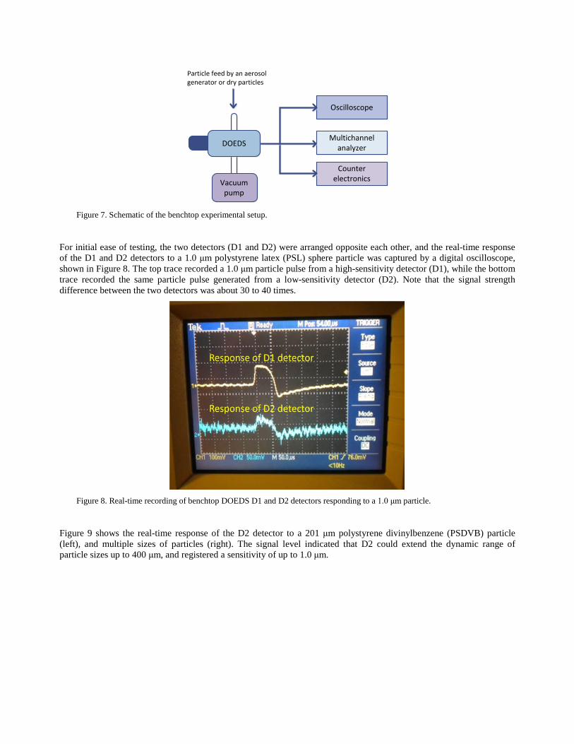
Figure 7. Schematic of the benchtop experimental setup.
For initial ease of testing, the two detectors (D1 and D2) were arranged opposite each other, and the real-time response of the D1 and D2 detectors to a 1.0 μm polystyrene latex (PSL) sphere particle was captured by a digital oscilloscope, shown in Figure 8. The top trace recorded a 1.0 μm particle pulse from a high-sensitivity detector (D1), while the bottom trace recorded the same particle pulse generated from a low-sensitivity detector (D2). Note that the signal strength difference between the two detectors was about 30 to 40 times.
Figure 8. Real-time recording of benchtop DOEDS D1 and D2 detectors responding to a 1.0 μm particle.
Figure 9 shows the real-time response of the D2 detector to a 201 μm polystyrene divinylbenzene (PSDVB) particle (left), and multiple sizes of particles (right). The signal level indicated that D2 could extend the dynamic range of particle sizes up to 400 μm, and registered a sensitivity of up to 1.0 μm.
Particle feed by an aerosol generator or dry particles
Oscilloscope
Multichannel analyzer
Counter electronics
DOEDS
Vacuum pump
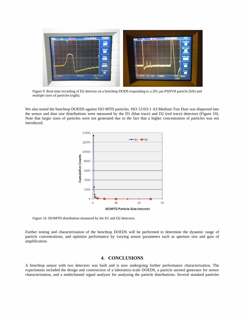
Figure 9. Real-time recording of D2 detector on a benchtop DODS responding to a 201 μm PSDVB particle (left) and multiple sizes of particles (right).
We also tested the benchtop DOEDS against ISO MTD particles. ISO 12103-1 A3 Medium Test Dust was dispersed into the sensor and dust size distributions were measured by the D1 (blue trace) and D2 (red trace) detectors (Figure 10). Note that larger sizes of particles were not generated due to the fact that a higher concentration of particles was not introduced.
Figure 10. ISOMTD distribution measured by the D1 and D2 detectors.
Further testing and characterization of the benchtop DOEDS will be performed to determine the dynamic range of particle concentrations, and optimize performance by varying sensor parameters such as aperture size and gain of amplification.
4. CONCLUSIONS A benchtop sensor with two detectors was built and is now undergoing further performance characterization. The experiments included the design and construction of a laboratory-scale DOEDS, a particle aerosol generator for sensor characterization, and a multichannel signal analyzer for analyzing the particle distributions. Several standard particles

(PSL and ISO MTD) were introduced to the sensor. The results indicate an excellent ability to detect and quantify the particle size and distribution, and hence concentrations. Preliminary analysis of the laboratory tests indicates that the DOEDS is capable of achieving a better than 1.0 μm sensitivity and up to 200 μm size range at a flow of 0.1 cfm. In addition to the laboratory experiments, we identified the most suitable sensor locations and the most appropriate mounting system (including thermal isolation), and completed the optical system concept development. Our simulation analysis through the engine compressor stages reveals that the root cause of particle penetration to the engine may be identified by changes in particle size distributions, which are capable of being measured by the DOEDS. Other competing techniques such as induction sensors cannot measure size distribution and cannot be used to determine the root cause of failure. Future work will entail the complete characterization of a benchtop sensor and refinement of the sensor design, placement, and packaging requirements.
The development of the dual optical embedded sensor/system outlined here will be directly applicable to engines of all military vehicles including trucks, tanks, helicopters, and other aircraft for protection against sand and dust, and early warning of air filter or seal breakdown, with only modest (if any) changes to the packaging and attachment of the sensor.
ACKNOWLEDGMENTS
This work was funded by the U.S. Army Tank Automotive Research, Development and Engineering Center (TARDEC) under Contract No. W56HZV-11-C-0320.
REFERENCES
[1] Scala, S. M., Konrad, M., Mason, R. B., Semick, J., and Skelton, D., "Sensor requirements to monitor the real time performance of a gas turbine engine undergoing compressor blade erosion," AIAA Paper 2004-3548, 40th AIAA/ASME/SAE/ASEE Joint Propulsion Conference, Fort Lauderdale, FL, 11-14 July (2004).
[2] Treuhaft, M. B., "Analysis of particle size data," Final Report, SwRI Project No. 03-11566, Southwest Research Institute, prepared for Physical Optics Corporation (2005).
[3] Shnitser, P. and Resnikov, M., "Size and number dust (SAND) detector," Final Report, Contract DAAE07-03-C-L009, Physical Optics Corporation (2006).
[4] Bohren, C. F. and Huffman, D. R., [Absorption and Scattering of Light by Small Particles], Wiley-Interscience, New York (1983).
[5] Xu, R., [Particle Characterization: Light Scattering Methods], Kluwer Academic Publishers, Dordrecht (2000). [6] Leipertz, A. and Sommer, R., "Time-resolved laser-induced incandescence," Advances in Chemical Engineering 37,
223-269 (2009).