Embed Size (px)
Citation preview
Astronomical Instrumentation course lecture 7a Dec 15, 2010
Frans Snik BBL 710 [email protected]
optical design a very rough overview…

requirements definition
• FOV • (effective) focal length • spatial resolution (+ sampling) • spectral range & resolution (+ sampling) • polarimetric performance • transmission • stability • etc.
optical design

boundary conditions
• telescope • telescope interfaces (see next lecture) • focal station dimensions • focal station gravity vector • detector availability • available € or $
optical design

global set-up
• lenses or mirrors (depends on wavelength range) • choice of dispersing elements (prism, grating) • location of aperture stop • locations of image and pupil planes • sampling (Nyquist: >2 pixels per resolution
element) • (dichroic) beam-splitting • etc.
optical design
global set-up
• (de-)magnification • F-numbers
– the amount of problems with aberrations increases with smaller F-number…
• collimated beam? • telecentric beam?
optical design
global set-up optical design
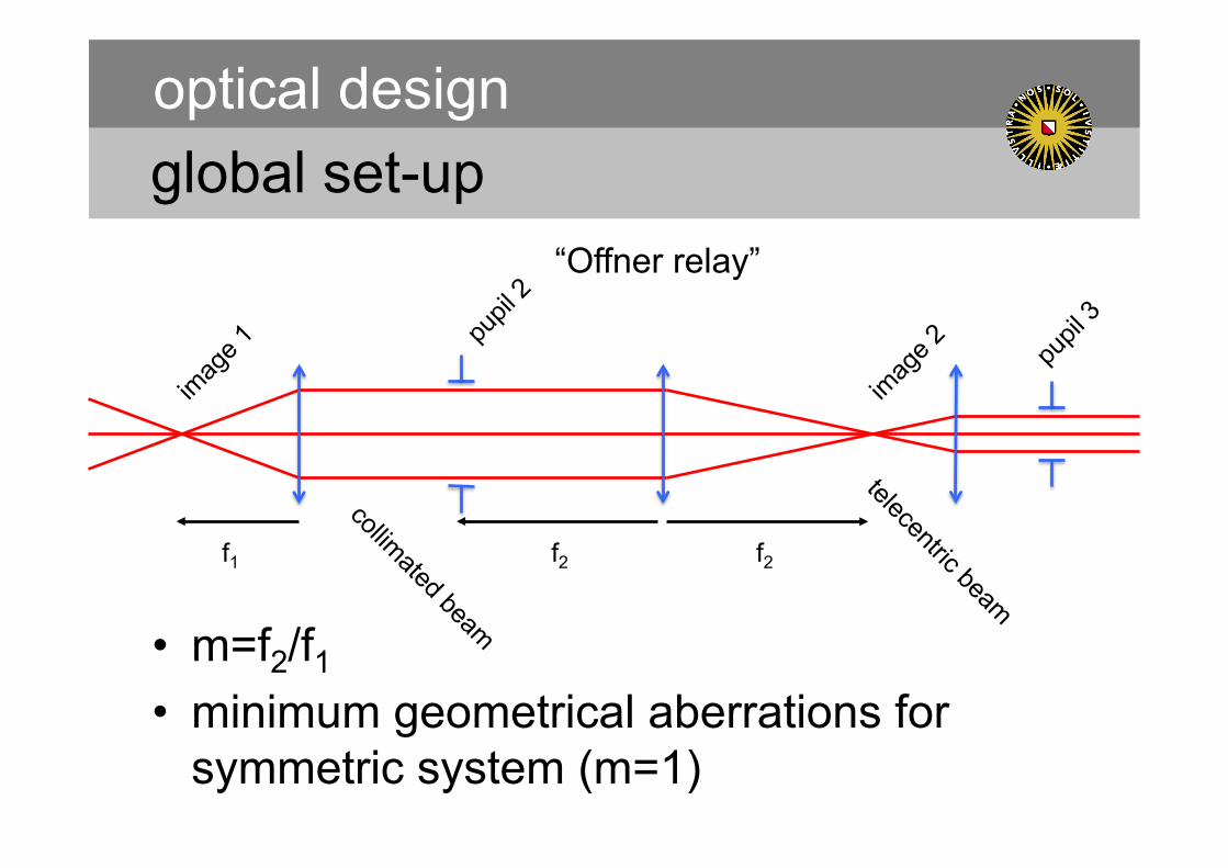
• m=f2/f1 • minimum geometrical aberrations for
symmetric system (m=1)
f1 f2 f2
“Offner relay”

global set-up
• components in collimated beam? – dispersion element – cold stop – Lyot stop – filter? – polarization modulator?
• components in converging beam? – slit – coronagraphic mask – detector – filter?
optical design

étendue
• or “throughput” or “grasp”, connected with “Lagrange invariant” or “optical invariant”
• derived from conservation of energy
• considered in every pupil plane: – 3D: aperture*FOV = A*Ω = constant – 2D: d*θ = constant
• unless focal ratio degradation in fibers…
optical design

block diagram optical design
EPICS-EPOL

block diagram optical design
SPICES
ray tracing
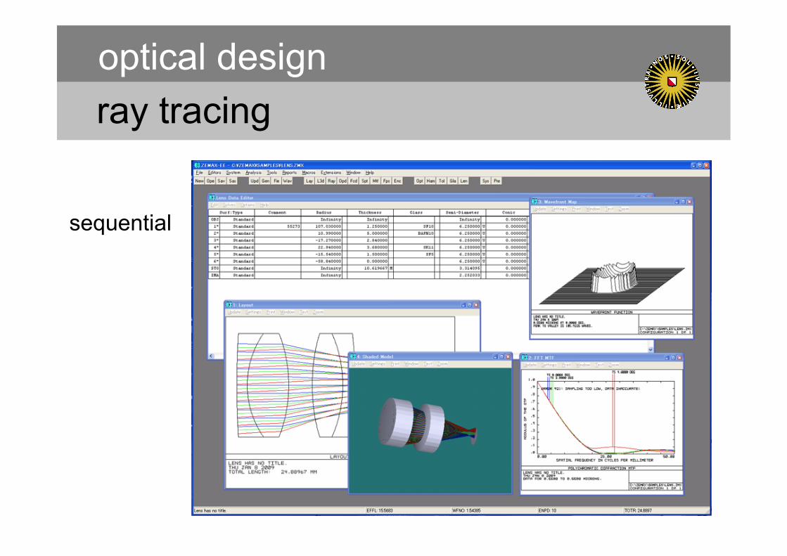
• used in optical design programs: – WinLens – ZEMAX – OSLO – CodeV – etc.
• Such programs are only useful when major design decisions have already been made!
optical design

ray tracing
• direction cosines v=(γ,δ,ε) – γ = cos θ – δ = cos φ – ε = cos ψ
• propagation along distance s measured in z direction: – x2 = γs/ε + x1
– y2 = δs/ε + y1
– z2 = s + z1
optical design
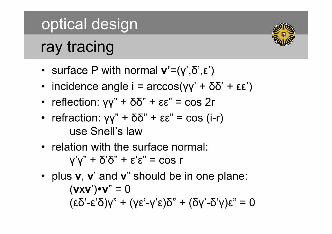
ray tracing • surface P with normal v’=(γ’,δ’,ε’) • incidence angle i = arccos(γγ’ + δδ’ + εε’) • reflection: γγ” + δδ” + εε” = cos 2r • refraction: γγ” + δδ” + εε” = cos (i-r)
use Snell’s law • relation with the surface normal:
γ’γ” + δ’δ” + ε’ε” = cos r • plus v, v’ and v” should be in one plane:
(vxv’)v” = 0 (εδ’-ε’δ)γ” + (γε’-γ’ε)δ” + (δγ’-δ’γ)ε” = 0
optical design

ray tracing
• sequential – from one surface to the next along the z axis – populate the pupil with rays – wavelength λ, field [x,y] as global parameters
• non-sequential – specific 3D volume and fire off rays in all
directions
optical design
ray tracing optical design
sequential
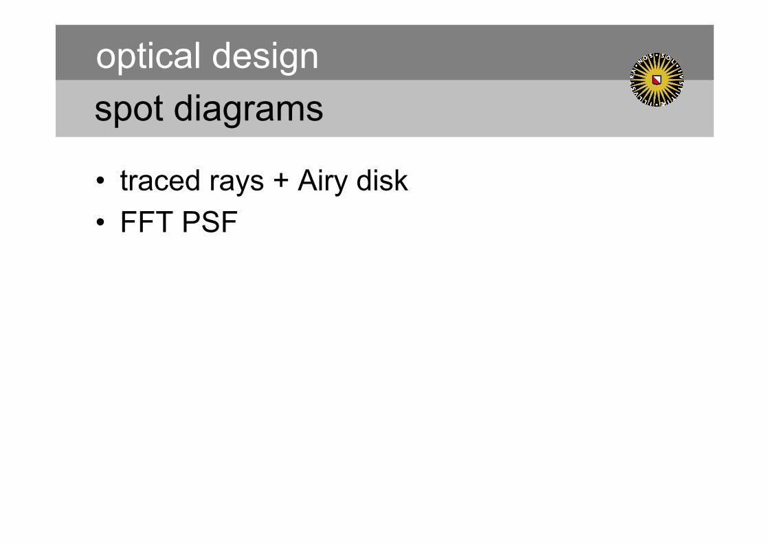
spot diagrams
• traced rays + Airy disk • FFT PSF
optical design

spot diagrams optical design
Jan Apr Jul
custom spherical doublets
S5T

aberration plots
• transverse / longitudinal aberration • Seidel diagram
optical design

optimization
• variables: – positions – angles – radii of curvature – conic constants – glass type – coating layers and material – etc.
optical design
optimization
• merit function • weighted linear combination of:
– system: • effective focal length
– spot: • centroid position • RMS radius • MTF • Strehl ratio (observed peak intensity / maximum peak intensity) • encircled energy
– coating polarization properties – etc
optical design

design examples optical design
SOLIS-VSM
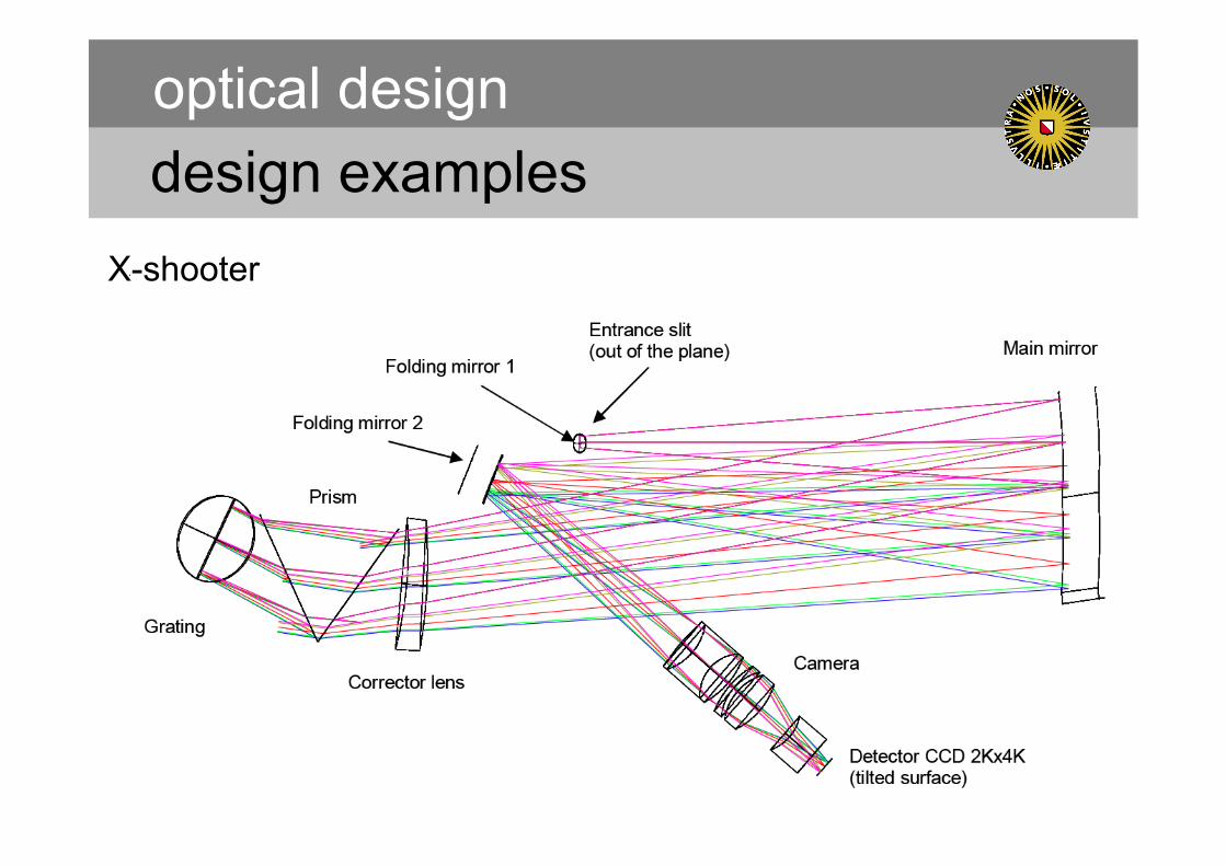
design examples optical design
X-shooter

design examples optical design
X-shooter
simulated from optical design measured

tolerancing
• spot diagram diffraction limited with margin?
• sensitivity analysis for individual elements • in the end: Monte Carlo
optical design

tolerancing optical design

tolerancing optical design
• example: EPICS-EPOL
stray light analysis
• look at where “second order” light ends up in non-sequential ray tracing
• or light outside FOV (in sequential ray tracing)
• solutions: – baffling – “ghosts”: defocus or tilt surfaces to move
outside FOV
optical design
Astronomical Instrumentation course lecture 7b Dec 15, 2010
Frans Snik BBL 710 [email protected]
systems engineering

why?
• Consider instrument as being more than just sum of its parts (subsystems).
• Crucial for complex instruments. • Implement from beginning of the project. • Interaction with optical, mechanical,
electronic, software design. • Interaction between different international
teams (interfaces).
systems engineering
budgets
• wavefront error • transmission • thermal background • radial velocity • polarimetric accuracy • etc.
• financial!
systems engineering
budgets
• top-down or bottom-up? • first: distribution of best guess • add quadratically or linearly? • continuously update during design process
and evaluate • identify (critical) issues that contribute
substantially to overall degradation of performance, and take action to mitigate
systems engineering

budgets
• system – subsystem A
• component 1 • component 2
– subsystem B • component 3 • component 4 • component 5
• total
systems engineering
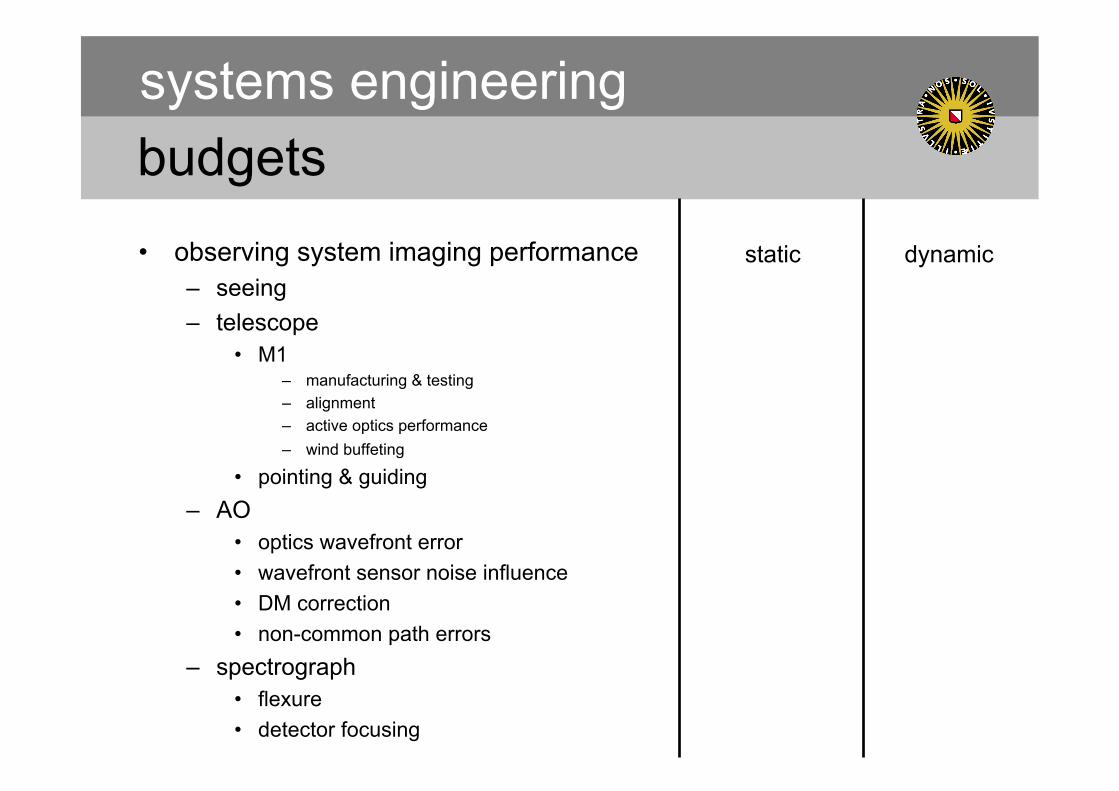
budgets • observing system imaging performance
– seeing – telescope
• M1 – manufacturing & testing – alignment – active optics performance – wind buffeting
• pointing & guiding – AO
• optics wavefront error • wavefront sensor noise influence • DM correction • non-common path errors
– spectrograph • flexure • detector focusing
systems engineering
static dynamic

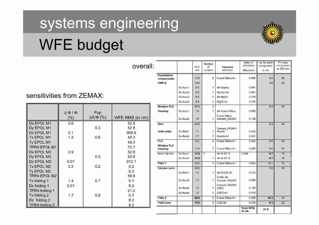
WFE budget
• magnitude of error in [nm] • decomposition in spatial frequencies or
Zernike polynomials • location: close to pupil plane or image
plane? • sensitivity analysis in optical design to
assess whether or not a certain error is critical
systems engineering
WFE budget systems engineering
sensitivities from ZEMAX:
overall:
interaction w/ mechanical design
• mounting precision [x,y,x], [φ,χ,ψ] from optical design
• optics deformation from mechanical design and finite element modeling
• several iterations of loop between optical and mechanical design
systems engineering

cryogenic instruments
• alignment at room temperature • contraction and deformation due to cool-down • cryogenic alignment mechanisms
• ZEMAX allows for lengths to be determined by metal at certain temperature
• mirrors, mounts and bench out of aluminum: focus invariant
• invar material
systems engineering
transmission budget
• reduce number of surfaces (>1% loss per surface)
• optimize coatings
• main ingredient for photon budget, plus photon noise and readout noise
• exposure time calculator: S/N for science goal feasible within a night?
systems engineering

transmission budget systems engineering
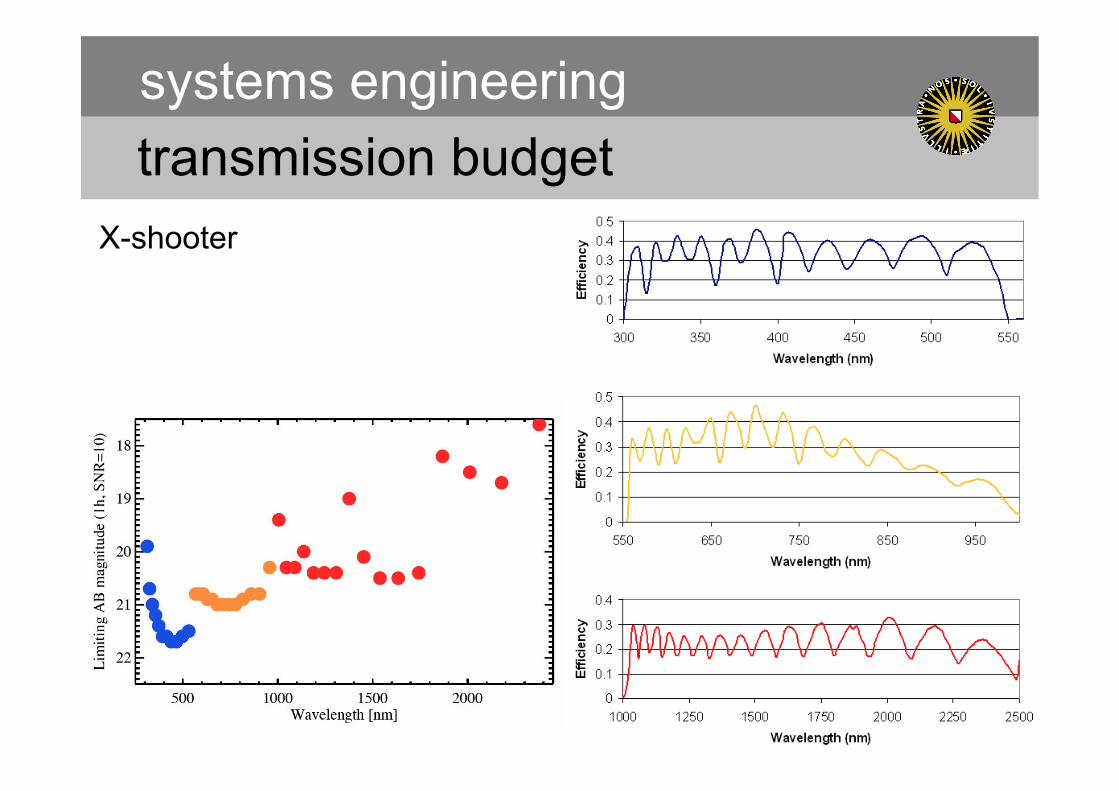
transmission budget systems engineering
X-shooter

controlling complexity
• number of moving parts • thermal control • vacuum systems • number of observing modes
• deal with single-point failures – redundancy
systems engineering

requirements verification
• verification matrix for lab tests • traceability to science requirements
– What is the science impact if a certain spec cannot be achieved?
systems engineering