Embed Size (px)
Citation preview
Antennen · Electronic
Optical Broadband Platform
NEW: Passive optical components
2 3
Optical Broadband Platform
• Optical broadband platform for up to 16 modules
• Equipped with 2 redundant power supply and fan units
• Wide selection of optical transmitters, amplifiers and return path receivers
• All optical and electrical connections are located on the rear panel. Test sockets are on the front panel • Can be integrated in every HMS-conform monitoring system
• Pluggable control panel with LC display, LEDs and input keys
• Tuning and management also via web browser
• RS 485 remote monitoring and control interface
• Several optical broadband platforms can be managed using just one controller module • Automatic redundant operation of adjacent modules
• High reliability due to dust-proof designed modules and large cooling ribs
• Models available for mains voltage (100...240 VAC) and direct voltage (36...72 VDC)
• Design: 19” racking, 4 height units (HU)
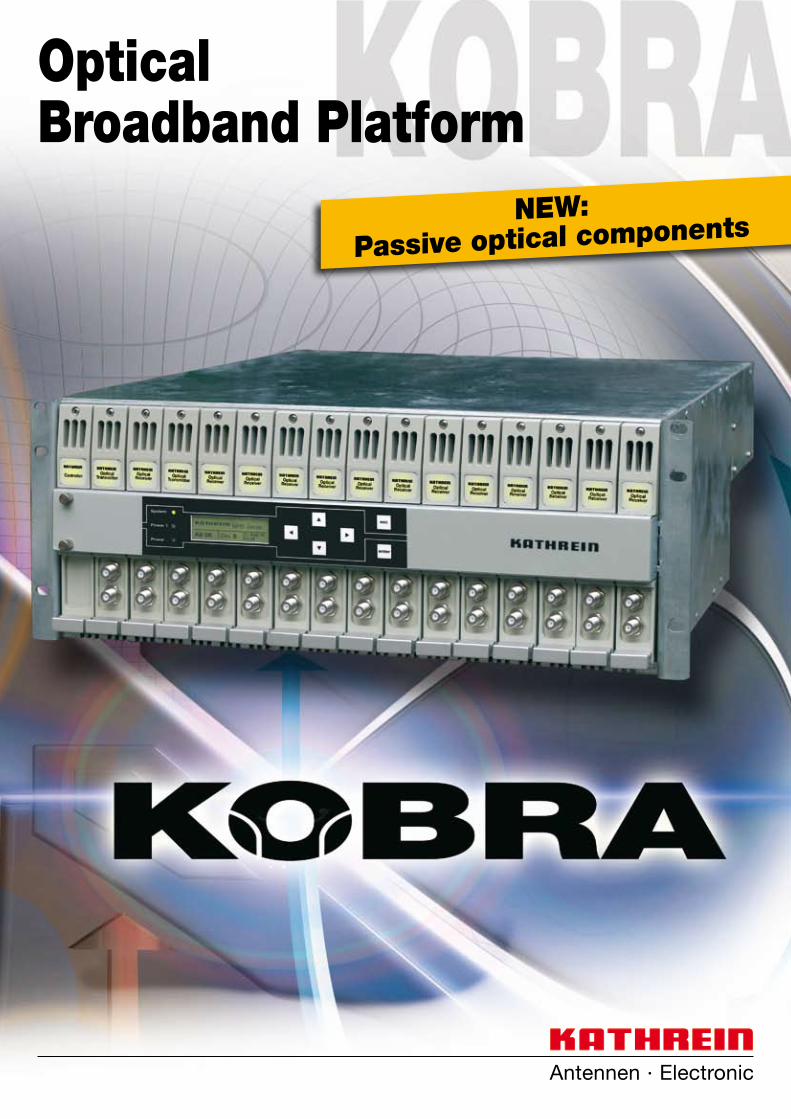
The net element controller module Ethernet (NCM 10) plays the leading role in this func-tion. This unit establishes the connection between the control panel and all plugged-in modules via the RS 485 bus. The NCM 10 can thereby control up to three full KBP 4000R or 4048R broadband platforms.
Kathrein's KOBRA system offers a compre-hensive broadband platform meeting all the requirements of optical transmission. A wide range of optical transmitters, amplifiers and return path receivers is complemented by individual units in 19” design.
The foundation is based on the 19” broad-band platform KBP 4000R, into which a total of 16 modules can be inserted. It is already equipped with two redundant power supply and fan units ensuring reliable operation. The product package additionally includes a pluggable control panel with LC display, status LEDs and input keys.
A power bus system in the rear section of the platform enables direct module connection to the 24 VDC supply voltage, to the RS 485 remote supervision and control interface as well as to control panel management.
On the other hand, it converts the RS 485 data to SNMP/Ethernet and web browser/Ethernet protocol. Thus, all settings and queries can be carried out via PC with a web browser. In addition, it is possible to integrate the broadband platform in any HMS-com-patible monitoring system such as the KOM system from Kathrein.
Together with the Kathrein optical compact receivers, the KOBRA can be used to set up an optical distribution system that meets each and every requirement. Modular design and a broad product programme make it possible to design anything in a cost-effective fashion from simple optical feeds to classical HFC structures and video distribution in FTTH networks.
Kathrein are continually enhancing their products and expanding their product range. Additional product variants are available upon request.
The broadband platform is designed as a 4 HU module carrier and can also be adapt-ed to ETSI cabinets. For use in hubs, forexample, the remotely fed broadband plat-form 48 VDC variant (KBP 4048R) can also be used.
Extensive management and monitoring facilities allow flexible and reliable operation in any net configuration. The provided pluggable control panel enables all required settings to be made on inserted devices.
4 5
Functional and reliable - the optical broadband platform in detail
Power supply
Module 2
Module 3
Gerät 16
LCDisplay
InputKeys
Ethernet
NCM 10I/0
RS485
µP
+24 VDC
Module 16
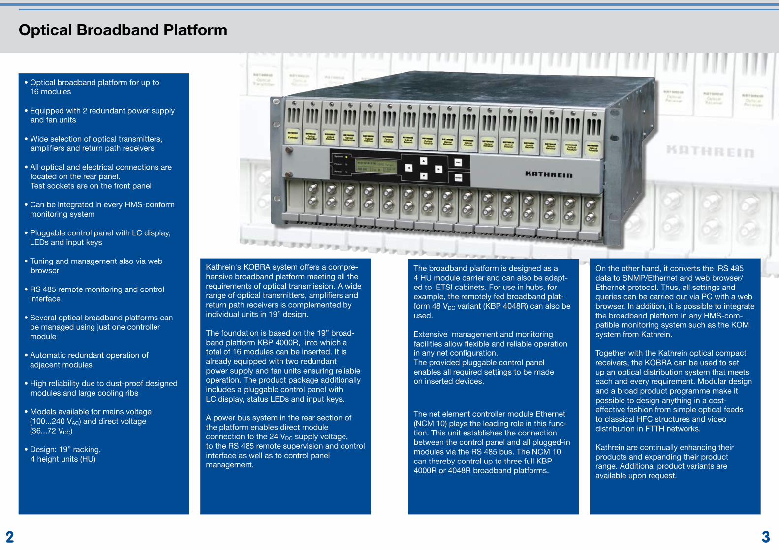
Power supplyThe optical broadband platform KOBRA is designed with a sophisticated operation and management concept. The central element is the net element controller Ethernet "NCM 10“. This module provides the inter-face to the rear RS 485 bus to which all plat-form modules are connected. In addition, it establishes the connection to external man-agement systems, e.g. via web browser, or monitoring systems, such as HMS monitor-ing systems.
Ultimately, it enables local setting of all parameters through the control panel with display and input keys. Decentralized data storage in each individual module allows independent operation (without the controller module) after start-up.
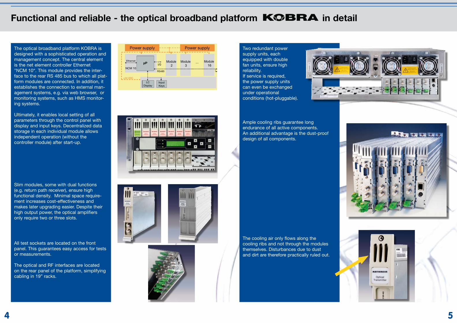
Slim modules, some with dual functions (e.g. return path receiver), ensure high functional density. Minimal space require-ment increases cost-effectiveness and makes later upgrading easier. Despite their high output power, the optical amplifiers only require two or three slots.
All test sockets are located on the front panel. This guarantees easy access for tests or measurements.
The optical and RF interfaces are located on the rear panel of the platform, simplifying cabling in 19” racks.
Two redundant power supply units, each equipped with double fan units, ensure high reliability. If service is required, the power supply units can even be exchanged under operational conditions (hot-pluggable).
Ample cooling ribs guarantee long endurance of all active components. An additional advantage is the dust-proof design of all components.
The cooling air only flows along the cooling ribs and not through the modules themselves. Disturbances due to dust and dirt are therefore practically ruled out.
6 7
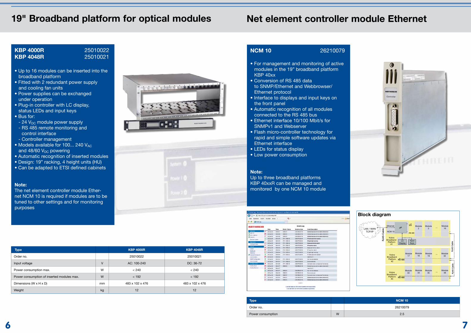
19" Broadband platform for optical modules
• Up to 16 modules can be inserted into the broadband platform• Fitted with 2 redundant power supply and cooling fan units• Power supplies can be exchanged under operation• Plug-in controller with LC display, status LEDs and input keys• Bus for: - 24 VDC module power supply - RS 485 remote monitoring and control interface - Controller management• Models available for 100... 240 VAC and 48/60 VDC powering• Automatic recognition of inserted modules • Design: 19” racking, 4 height units (HU)• Can be adapted to ETSI defined cabinets
Note: The net element controller module Ether-net NCM 10 is required if modules are to be tuned to other settings and for monitoring purposes
KBP 4000R 25010022KBP 4048R 25010021
Type KBP 4000R KBP 4048R
Order no. 25010022 25010021
Input voltage V AC: 100-240 DC: 36-72
Power consumption max. W < 240 < 240
Power consumption of inserted modules max. W < 192 < 192
Dimensions (W x H x D) mm 483 x 102 x 476 483 x 102 x 476
Weight kg 12 12
Net element controller module Ethernet
• Zum Management und Überwachung aktiver Module in der 19“-Breitband- Plattform KBP 40xx• Umwandlung von RS 485-Daten in SNMP/Ethernet- und Webbrowser/ Ethernet-Protokoll• Schnittstelle zu Displays und Eingabetasten der Fronteinheit• Automatische Erkennung aller an den RS 485-Bus angeschlossenen Module• Schnittstelle Ethernet 10/100 Mbit/s für SNMPv1 und Webserver• Flash Microcontroller-Technologie für schnelle und leichte Software-Updates über die Ethernet-Schnittstelle• LEDs zur Statusanzeige• Niedrige Leistungsaufnahme
Hinweis: Ein NCM 10 kann bis zu drei Breitband-Plattformen KBP 40xxR verwalten und überwachen
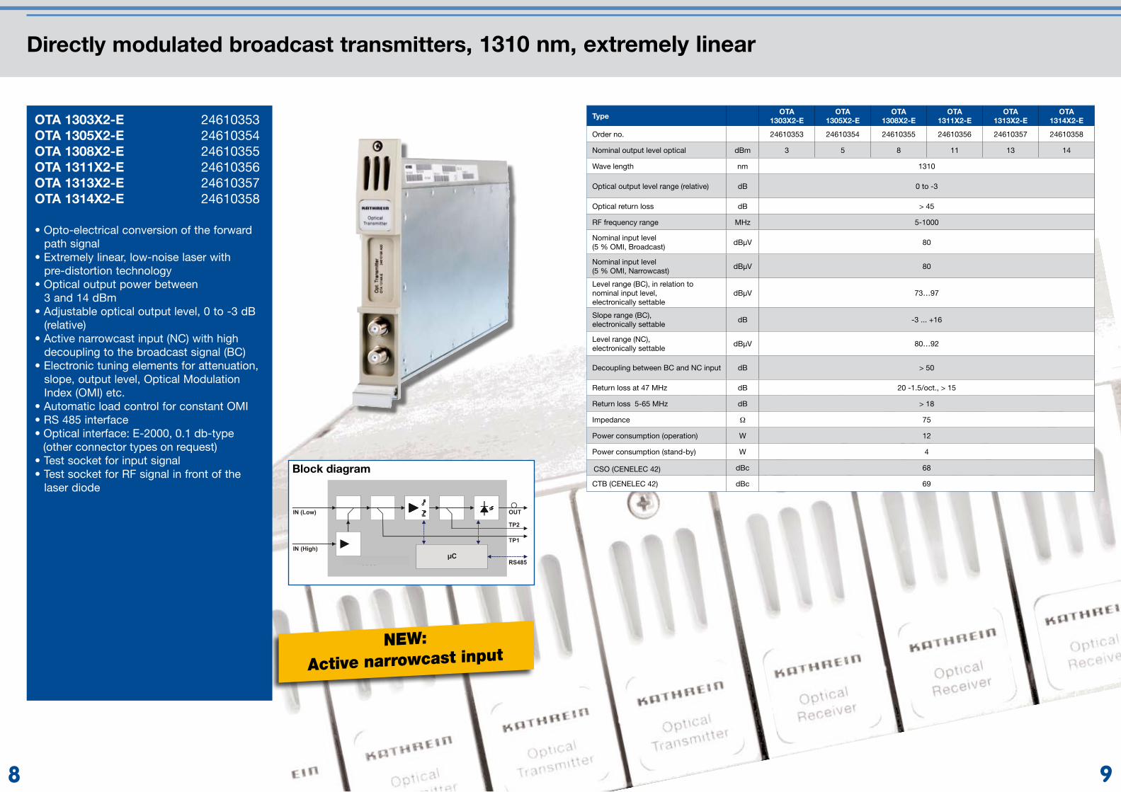
• For management and monitoring of active modules in the 19” broadband platform KBP 40xx• Conversion of RS 485 data to SNMP/Ethernet and Webbrowser/ Ethernet protocol• Interface to displays and input keys on the front panel • Automatic recognition of all modules connected to the RS 485 bus• Ethernet interface 10/100 Mbit/s for SNMPv1 and Webserver• Flash micro-controller technology for rapid and simple software updates via Ethernet interface• LEDs for status display• Low power consumption
Note: Up to three broadband platforms KBP 40xxR can be managed and monitored by one NCM 10 module
NCM 10 26210079
Type NCM 10
Order no. 26210079
Power consumption W 2.5
LAN / WANTCP/IP
Ethernet
NCM 10
Module2
Module3
Module17
Module18
Module19
Module32
Module33
Module34
Module35
Module48
µP
RJ4
5 C
able
RJ4
5 C
able
RJ4
5-C
able
Module16
KobraBroadband
Platform#3
KobraBroadband
Platform#2
KobraBroadband
Platform#1
I/O
RS 485
RS 485
RS 485
InputKeys
LCDisplay
Block diagram
98
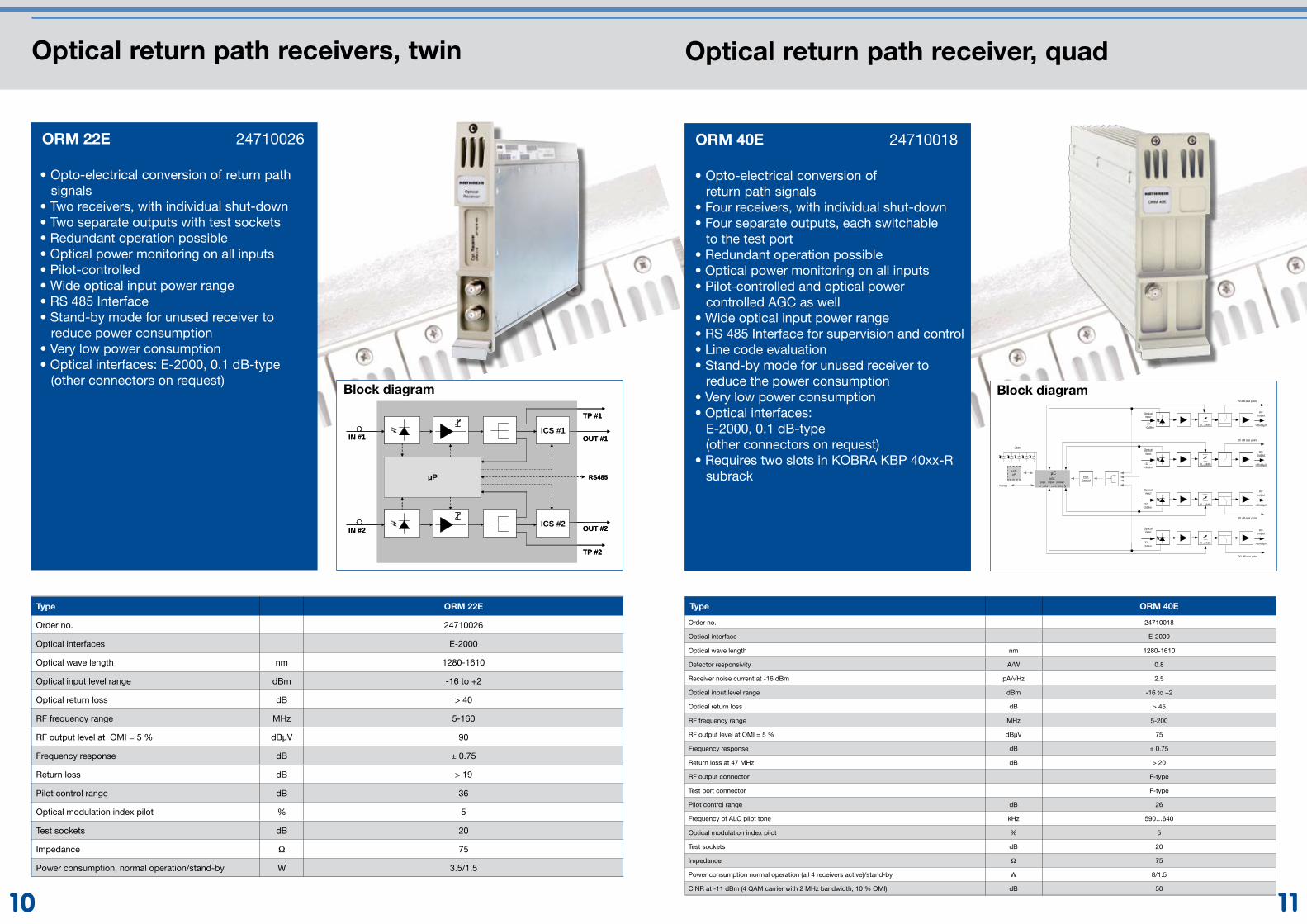
Directly modulated broadcast transmitters, 1310 nm, extremely linear
• Opto-electrical conversion of the forward path signal• Extremely linear, low-noise laser with pre-distortion technology• Optical output power between 3 and 14 dBm• Adjustable optical output level, 0 to -3 dB (relative)• Active narrowcast input (NC) with high decoupling to the broadcast signal (BC)• Electronic tuning elements for attenuation, slope, output level, Optical Modulation Index (OMI) etc.• Automatic load control for constant OMI• RS 485 interface• Optical interface: E-2000, 0.1 db-type (other connector types on request)• Test socket for input signal• Test socket for RF signal in front of the laser diode
OTA 1303X2-E 24610353OTA 1305X2-E 24610354OTA 1308X2-E 24610355OTA 1311X2-E 24610356OTA 1313X2-E 24610357OTA 1314X2-E 24610358
TypeOTA
1303X2-EOTA
1305X2-EOTA
1308X2-EOTA
1311X2-EOTA
1313X2-EOTA
1314X2-E
Order no. 24610353 24610354 24610355 24610356 24610357 24610358
Nominal output level optical dBm 3 5 8 11 13 14
Wave length nm 1310
Optical output level range (relative) dB 0 to -3
Optical return loss dB > 45
RF frequency range MHz 5-1000
Nominal input level (5 % OMI, Broadcast)
dBµV 80
Nominal input level (5 % OMI, Narrowcast)
dBµV 80
Level range (BC), in relation to nominal input level, electronically settable
dBµV 73…97
Slope range (BC), electronically settable
dB -3 ... +16
Level range (NC), electronically settable
dBµV 80…92
Decoupling between BC and NC input dB > 50
Return loss at 47 MHz dB 20 -1.5/oct., > 15
Return loss 5-65 MHz dB > 18
Impedance Ω 75
Power consumption (operation) W 12
Power consumption (stand-by) W 4
CSO (CENELEC 42) dBc 68
CTB (CENELEC 42) dBc 69
NEW:
Active narrowcast input
Block diagram
1110
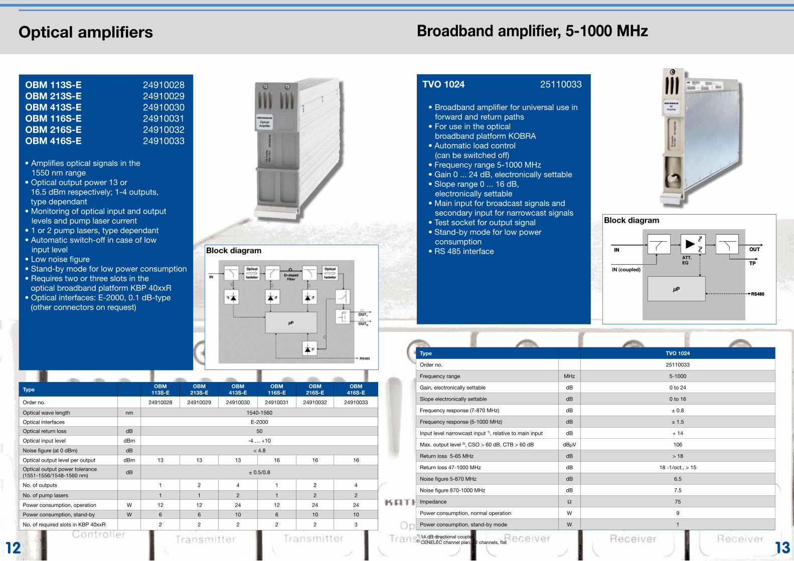
Optical return path receiver, quad
• Opto-electrical conversion of return path signals• Four receivers, with individual shut-down• Four separate outputs, each switchable to the test port• Redundant operation possible• Optical power monitoring on all inputs • Pilot-controlled and optical power controlled AGC as well• Wide optical input power range• RS 485 Interface for supervision and control• Line code evaluation• Stand-by mode for unused receiver to reduce the power consumption• Very low power consumption• Optical interfaces: E-2000, 0.1 dB-type (other connectors on request)• Requires two slots in KOBRA KBP 40xx-R subrack
ORM 40E 24710018
Type ORM 40E
Order no. 24710018
Optical interface E-2000
Optical wave length nm 1280-1610
Detector responsivity A/W 0.8
Receiver noise current at -16 dBm pA/√Hz 2.5
Optical input level range dBm -16 to +2
Optical return loss dB > 45
RF frequency range MHz 5-200
RF output level at OMI = 5 % dBµV 75
Frequency response dB ± 0.75
Return loss at 47 MHz dB > 20
RF output connector F-type
Test port connector F-type
Pilot control range dB 26
Frequency of ALC pilot tone kHz 590…640
Optical modulation index pilot % 5
Test sockets dB 20
Impedance Ω 75
Power consumption normal operation (all 4 receivers active)/stand-by W 8/1.5
CINR at -11 dBm (4 QAM carrier with 2 MHz bandwidth, 10 % OMI) dB 50
Block diagram
Optical return path receivers, twin
ORM 22E 24710026
IN #1
OR265-nn
OUT #1
TP #1
µP RS485
ICS #1
IN #2 OUT #2
TP #2
ICS #2
IN #1 OUT #1
TP #1
µP RS485
ICS #1
IN #2 OUT #2
TP #2
ICS #2
Type ORM 22E
Order no. 24710026
Optical interfaces E-2000
Optical wave length nm 1280-1610
Optical input level range dBm -16 to +2
Optical return loss dB > 40
RF frequency range MHz 5-160
RF output level at OMI = 5 % dBµV 90
Frequency response dB ± 0.75
Return loss dB > 19
Pilot control range dB 36
Optical modulation index pilot % 5
Test sockets dB 20
Impedance Ω 75
Power consumption, normal operation/stand-by W 3.5/1.5
Block diagram
Opticalinput
-22 ...+2dBm
0...10dB0...10dB0...24dB
RFoutput
>85dBµV
Opticalinput
0...10dB0...10dB0...24dB
RFoutput
>85dBµV
Opticalinput
0...10dB0...10dB0...24dB
RFoutput
>85dBµV
Opticalinput
0...10dB0...10dB0...24dB
RFoutput
>85dBµV
AGC(opt. input power
or pilot controlled )))
µC
-22 ...+2dBm
-22 .. .+2dBm
-22 .. .+2dBm
PSKDemod
LONµP
LEDs
RS485
20 dB test point
20 dB test point
20 dB test point
20 dB test point
• Opto-electrical conversion of return path signals• Two receivers, with individual shut-down• Two separate outputs with test sockets• Redundant operation possible• Optical power monitoring on all inputs• Pilot-controlled• Wide optical input power range• RS 485 Interface• Stand-by mode for unused receiver to reduce power consumption • Very low power consumption• Optical interfaces: E-2000, 0.1 dB-type (other connectors on request)
12 13
TypeOBM
113S-EOBM
213S-EOBM
413S-EOBM
116S-EOBM
216S-EOBM
416S-E
Order no. 24910028 24910029 24910030 24910031 24910032 24910033
Optical wave length nm 1540-1560
Optical interfaces E-2000
Optical return loss dB 50
Optical input level dBm -4 … +10
Noise figure (at 0 dBm) dB < 4.8
Optical output level per output dBm 13 13 13 16 16 16
Optical output power tolerance (1551-1556/1548-1560 nm)
dB ± 0.5/0.8
No. of outputs 1 2 4 1 2 4
No. of pump lasers 1 1 2 1 2 2
Power consumption, operation W 12 12 24 12 24 24
Power consumption, stand-by W 6 6 10 6 10 10
No. of required slots in KBP 40xxR 2 2 2 2 2 3
Broadband amplifier, 5-1000 MHz
TVO 1024 25110033
IN
CA1024
OUT
TP
µPRS485
ATT, EQ
IN (coupled)
IN OUT
TP
µPRS485
ATT, EQ
Block diagram
1) 14 dB directional coupler2) CENELEC channel plan, 42 channels, flat
OBM 113S-E 24910028OBM 213S-E 24910029OBM 413S-E 24910030OBM 116S-E 24910031OBM 216S-E 24910032OBM 416S-E 24910033
Block diagram
Optical amplifiers
• Amplifies optical signals in the 1550 nm range• Optical output power 13 or 16.5 dBm respectively; 1-4 outputs, type dependant• Monitoring of optical input and output levels and pump laser current • 1 or 2 pump lasers, type dependant• Automatic switch-off in case of low input level• Low noise figure• Stand-by mode for low power consumption• Requires two or three slots in the optical broadband platform KBP 40xxR• Optical interfaces: E-2000, 0.1 dB-type (other connectors on request)
• Broadband amplifier for universal use in forward and return paths • For use in the optical broadband platform KOBRA• Automatic load control (can be switched off)• Frequency range 5-1000 MHz• Gain 0 ... 24 dB, electronically settable• Slope range 0 ... 16 dB, electronically settable• Main input for broadcast signals and secondary input for narrowcast signals• Test socket for output signal• Stand-by mode for low power consumption• RS 485 interface
Type TVO 1024
Order no. 25110033
Frequency range MHz 5-1000
Gain, electronically settable dB 0 to 24
Slope electronically settable dB 0 to 16
Frequency response (7-870 MHz) dB ± 0.8
Frequency response (5-1000 MHz) dB ± 1.5
Input level narrowcast input 1), relative to main input dB + 14
Max. output level 2), CSO > 60 dB, CTB > 60 dB dBµV 106
Return loss 5-65 MHz dB > 18
Return loss 47-1000 MHz dB 18 -1/oct., > 15
Noise figure 5-870 MHz dB 6.5
Noise figure 870-1000 MHz dB 7.5
Impedance Ω 75
Power consumption, normal operation W 9
Power consumption, stand-by mode W 1
1514
Block diagram
Block diagram
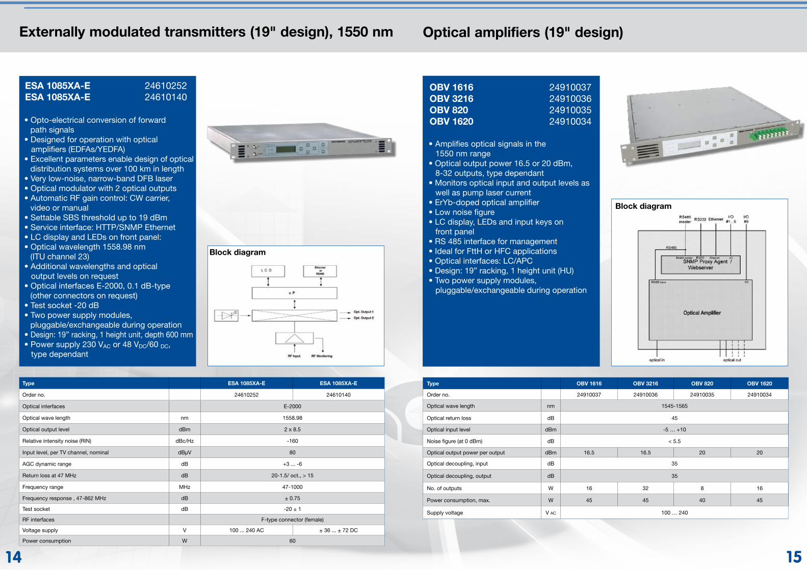
Externally modulated transmitters (19" design), 1550 nm
ESA 1085XA-E 24610252ESA 1085XA-E 24610140
• Opto-electrical conversion of forward path signals• Designed for operation with optical amplifiers (EDFAs/YEDFA)• Excellent parameters enable design of optical distribution systems over 100 km in length• Very low-noise, narrow-band DFB laser• Optical modulator with 2 optical outputs • Automatic RF gain control: CW carrier, video or manual • Settable SBS threshold up to 19 dBm• Service interface: HTTP/SNMP Ethernet• LC display and LEDs on front panel:• Optical wavelength 1558.98 nm (ITU channel 23)• Additional wavelengths and optical output levels on request• Optical interfaces E-2000, 0.1 dB-type (other connectors on request)• Test socket -20 dB• Two power supply modules, pluggable/exchangeable during operation• Design: 19” racking, 1 height unit, depth 600 mm• Power supply 230 VAC or 48 VDC/60 DC, type dependant
Type ESA 1085XA-E ESA 1085XA-E
Order no. 24610252 24610140
Optical interfaces E-2000
Optical wave length nm 1558.98
Optical output level dBm 2 x 8.5
Relative intensity noise (RIN) dBc/Hz -160
Input level, per TV channel, nominal dBµV 80
AGC dynamic range dB +3 ... -6
Return loss at 47 MHz dB 20-1.5/ oct., > 15
Frequency range MHz 47-1000
Frequency response , 47-862 MHz dB ± 0.75
Test socket dB -20 ± 1
RF interfaces F-type connector (female)
Voltage supply V 100 ... 240 AC ± 36 ... ± 72 DC
Power consumption W 60
Optical amplifiers (19" design)
OBV 1616 24910037OBV 3216 24910036OBV 820 24910035OBV 1620 24910034
• Amplifies optical signals in the 1550 nm range• Optical output power 16.5 or 20 dBm, 8-32 outputs, type dependant• Monitors optical input and output levels as well as pump laser current• ErYb-doped optical amplifier• Low noise figure• LC display, LEDs and input keys on front panel• RS 485 interface for management• Ideal for FttH or HFC applications• Optical interfaces: LC/APC• Design: 19” racking, 1 height unit (HU)• Two power supply modules, pluggable/exchangeable during operation
Type OBV 1616 OBV 3216 OBV 820 OBV 1620
Order no. 24910037 24910036 24910035 24910034
Optical wave length nm 1545-1565
Optical return loss dB 45
Optical input level dBm -5 … +10
Noise figure (at 0 dBm) dB < 5.5
Optical output power per output dBm 16.5 16.5 20 20
Optical decoupling, input dB 35
Optical decoupling, output dB 35
No. of outputs W 16 32 8 16
Power consumption, max. W 45 45 40 45
Supply voltage V AC 100 … 240
1716
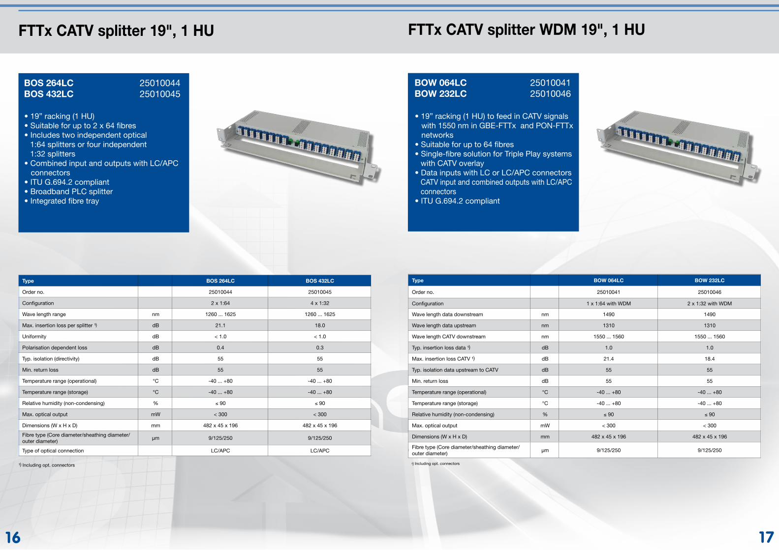
FTTx CATV splitter 19", 1 HU
BOS 264LC 25010044BOS 432LC 25010045
FTTx CATV splitter WDM 19", 1 HU
BOW 064LC 25010041BOW 232LC 25010046
• 19” racking (1 HU) to feed in CATV signals with 1550 nm in GBE-FTTx and PON-FTTx networks• Suitable for up to 64 fibres• Single-fibre solution for Triple Play systems with CATV overlay• Data inputs with LC or LC/APC connectors CATV input and combined outputs with LC/APC connectors• ITU G.694.2 compliant
¹) Einschließlich opt. Steckverbindungen
Type BOW 064LC BOW 232LC
Order no. 25010041 25010046
Configuration 1 x 1:64 with WDM 2 x 1:32 with WDM
Wave length data downstream nm 1490 1490
Wave length data upstream nm 1310 1310
Wave length CATV downstream nm 1550 ... 1560 1550 ... 1560
Typ. insertion loss data ¹) dB 1.0 1.0
Max. insertion loss CATV ¹) dB 21.4 18.4
Typ. isolation data upstream to CATV dB 55 55
Min. return loss dB 55 55
Temperature range (operational) °C -40 ... +80 -40 ... +80
Temperature range (storage) °C -40 ... +80 -40 ... +80
Relative humidity (non-condensing) % ≤ 90 ≤ 90
Max. optical output mW < 300 < 300
Dimensions (W x H x D) mm 482 x 45 x 196 482 x 45 x 196
Fibre type (Core diameter/sheathing diameter/outer diameter)
µm 9/125/250 9/125/250
• 19” racking (1 HU)• Suitable for up to 2 x 64 fibres• Includes two independent optical 1:64 splitters or four independent 1:32 splitters• Combined input and outputs with LC/APC connectors• ITU G.694.2 compliant• Broadband PLC splitter• Integrated fibre tray
Type BOS 264LC BOS 432LC
Order no. 25010044 25010045
Configuration 2 x 1:64 4 x 1:32
Wave length range nm 1260 ... 1625 1260 ... 1625
Max. insertion loss per splitter ¹) dB 21.1 18.0
Uniformity dB < 1.0 < 1.0
Polarisation dependent loss dB 0.4 0.3
Typ. isolation (directivity) dB 55 55
Min. return loss dB 55 55
Temperature range (operational) °C -40 ... +80 -40 ... +80
Temperature range (storage) °C -40 ... +80 -40 ... +80
Relative humidity (non-condensing) % ≤ 90 ≤ 90
Max. optical output mW < 300 < 300
Dimensions (W x H x D) mm 482 x 45 x 196 482 x 45 x 196
Fibre type (Core diameter/sheathing diameter/outer diameter)
µm 9/125/250 9/125/250
Type of optical connection LC/APC LC/APC
¹) Including opt. connectors ¹) Including opt. connectors
1918
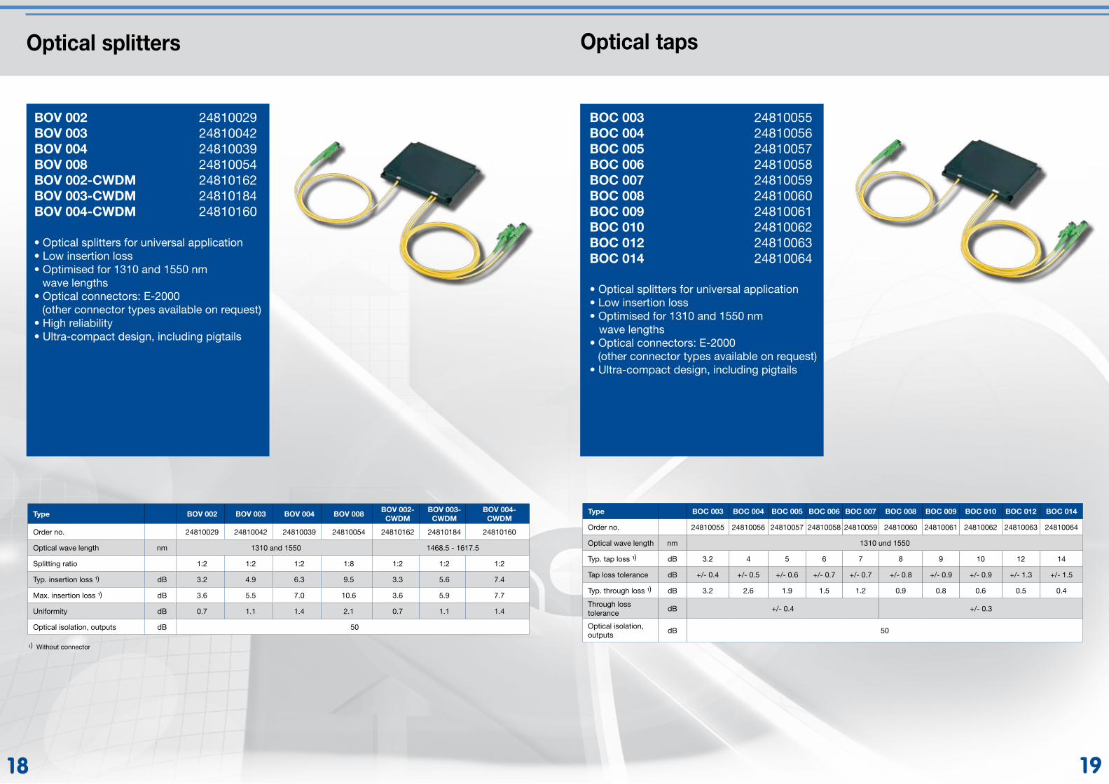
Optical taps
BOC 003 24810055BOC 004 24810056BOC 005 24810057BOC 006 24810058BOC 007 24810059BOC 008 24810060BOC 009 24810061BOC 010 24810062BOC 012 24810063BOC 014 24810064
Optical splitters
• Optical splitters for universal application• Low insertion loss• Optimised for 1310 and 1550 nm wave lengths• Optical connectors: E-2000 (other connector types available on request)• High reliability• Ultra-compact design, including pigtails
BOV 002 24810029BOV 003 24810042BOV 004 24810039BOV 008 24810054BOV 002-CWDM 24810162BOV 003-CWDM 24810184BOV 004-CWDM 24810160
Type BOV 002 BOV 003 BOV 004 BOV 008BOV 002-
CWDMBOV 003-
CWDMBOV 004-
CWDM
Order no. 24810029 24810042 24810039 24810054 24810162 24810184 24810160
Optical wave length nm 1310 and 1550 1468.5 - 1617.5
Splitting ratio 1:2 1:2 1:2 1:8 1:2 1:2 1:2
Typ. insertion loss ¹) dB 3.2 4.9 6.3 9.5 3.3 5.6 7.4
Max. insertion loss ¹) dB 3.6 5.5 7.0 10.6 3.6 5.9 7.7
Uniformity dB 0.7 1.1 1.4 2.1 0.7 1.1 1.4
Optical isolation, outputs dB 50
¹) Without connector
• Optical splitters for universal application• Low insertion loss• Optimised for 1310 and 1550 nm wave lengths• Optical connectors: E-2000 (other connector types available on request)• Ultra-compact design, including pigtails
Type BOC 003 BOC 004 BOC 005 BOC 006 BOC 007 BOC 008 BOC 009 BOC 010 BOC 012 BOC 014
Order no. 24810055 24810056 24810057 24810058 24810059 24810060 24810061 24810062 24810063 24810064
Optical wave length nm 1310 und 1550
Typ. tap loss ¹) dB 3.2 4 5 6 7 8 9 10 12 14
Tap loss tolerance dB +/- 0.4 +/- 0.5 +/- 0.6 +/- 0.7 +/- 0.7 +/- 0.8 +/- 0.9 +/- 0.9 +/- 1.3 +/- 1.5
Typ. through loss ¹) dB 3.2 2.6 1.9 1.5 1.2 0.9 0.8 0.6 0.5 0.4
Through loss tolerance
dB +/- 0.4 +/- 0.3
Optical isolation, outputs
dB 50
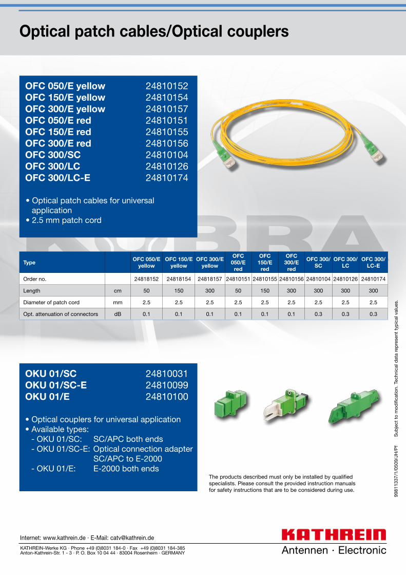
Optical patch cables/Optical couplers
• Optical patch cables for universal application• 2.5 mm patch cord
OFC 050/E yellow 24810152OFC 150/E yellow 24810154OFC 300/E yellow 24810157OFC 050/E red 24810151OFC 150/E red 24810155OFC 300/E red 24810156OFC 300/SC 24810104OFC 300/LC 24810126OFC 300/LC-E 24810174
TypeOFC 050/E
yellowOFC 150/E
yellowOFC 300/E
yellow
OFC 050/E
red
OFC 150/E
red
OFC 300/E
red
OFC 300/SC
OFC 300/LC
OFC 300/LC-E
Order no. 24818152 24818154 24818157 24810151 24810155 24810156 24810104 24810126 24810174
Length cm 50 150 300 50 150 300 300 300 300
Diameter of patch cord mm 2.5 2.5 2.5 2.5 2.5 2.5 2.5 2.5 2.5
Opt. attenuation of connectors dB 0.1 0.1 0.1 0.1 0.1 0.1 0.3 0.3 0.3
9981
1337
/1/0
509/
JH/P
f
S
ubje
ct t
o m
odifi
catio
n. T
echn
ical
dat
a re
pre
sent
typ
ical
val
ues.
Antennen · Electronic
The products described must only be installed by qualified specialists. Please consult the provided instruction manuals for safety instructions that are to be considered during use.
KATHREIN-Werke KG · Phone +49 (0)8031 184-0 · Fax +49 (0)8031 184-385Anton-Kathrein-Str. 1 - 3 · P. O. Box 10 04 44 · 83004 Rosenheim · GERMANY
Internet: www.kathrein.de · E-Mail: [email protected]
• Optical couplers for universal application• Available types: - OKU 01/SC: SC/APC both ends - OKU 01/SC-E: Optical connection adapter SC/APC to E-2000 - OKU 01/E: E-2000 both ends
OKU 01/SC 24810031OKU 01/SC-E 24810099OKU 01/E 24810100