Embed Size (px)
Citation preview
NASA Technical Memorandum 88844
Optical Alignment of Centaur's Inertial Guidance System
~ ___ ( h A S A - T F - 6 8 8 4 4 ) O P T I C A L A E I G E E & : N Z OF N88- 125 15 CELTWUE'S I N E E T I A L G U I Z A N C E SYSTEb (NASA) 1C8 F CSCL 143
U n c l a s G3/14 0310981
Andrew L. G a r b Lavis Research Center Cleveland, Ohio
December 1987
https://ntrs.nasa.gov/search.jsp?R=19880003133 2018-07-18T20:48:44+00:00Z

OPTICAL ALIGNMENT OF CENTAUR'S INERTIAL GUIDANCE SYSTEM
Andrew L. Gordan N a t i o n a l A e r o n a u t i c s and Space A d m i n i s t r a t i o n
Lewis Research Center C l e v e l a n d , Oh io 44135
SUMMARY
D u r i n g Centaur l aunch o p e r a t i o n s t h e l aunch az imuth o f t h e i n e r t i a l p l a t - form's U-accelerometer i n p u t a x i s must be a c c u r a t e l y e s t a b l i s h e d and main- t a i n e d . T h i s i s accompl ished by u s i n g an o p t i c a l l y c l o s e d l o o p system w i t h a long-range a u t o t h e o d o l i t e whose l i n e o f s i g h t has been e s t a b l i s h e d by a f irst-
UI o r d e r survey. A c o l l i m a t e d l i g h t beam from t h e a u t o t h e o d o l i t e i n t e r c e p t s a cu r e f l e c t i n g Porro p r i s m mounted on t h e p l a t f o r m az imu th g imba l . Thus, any N
I Cr)
W d e v i a t i o n o f t h e Porro p r i s m from i t s p rede te rm ined heading i s o p t i c a l l y d e t e c t e d by t h e a u t o t h e o d o l i t e . The error s i g n a l produced i s used t o t o r q u e t h e az imu th gimbal back t o i t s r e q u i r e d l aunch az imuth. The head ing o f t h e U-accelerometer i n p u t a x i s i s t h e r e f o r e m a i n t a i n e d a u t o m a t i c a l l y .
P r e v i o u s l y , t h e a u t o t h e o d o l i t e system c o u l d n o t d i s t i n g u i s h between v e h i c l e sway ( t r a n s l a t o r y m o t i o n ) and r o t a t i o n a l m o t i o n o f t h e i n e r t i a l p l a t - form u n l e s s a t l e a s t t h r e e p r i sms were used. i n e r t i a l p l a t f o r m t o m a i n t a i n az imu th a l i g n m e n t , and two p r i s m s were mounted e x t e r n a l l y on t h e v e h i c l e t o t r a c k sway. For example, t h e a u t o m a t i c az imuth- l a y i n g t h e o d o l i t e (AALT-SV-M2) on t h e S a t u r n v e h i c l e used t h r e e p r i s m s .
One p r i s m was mounted on t h e
T h i s r e p o r t documents and d e s c r i b e s t h e r e s u l t s o f t e s t i n g and m o d i f y i n g t h e AALT-SV-M2 a u t o t h e o d o l i t e t o s i m u l t a n e o u s l y m o n i t o r and m a i n t a i n a l i g n m e n t o f t h e i n e r t i a l p l a t f o r m and t r a c k t h e sway o f t h e v e h i c l e from a s i n g l e Porro p r i s m .
INTRODUCTION
T h i s r e p o r t documents t h e r e s u l t s of t e s t i n g and m o d i f y i n g t h e P e r k i n - E l m e r a u t o m a t i c a z i m u t h - l a y i n g t h e o d o l i t e (AALT-SV-M2> t o v e r i f y t h e f e a s i - b i l i t y o f o p e r a t i n g t h i s system from a s i n g l e D-1A Centaur Porro p r i s m a t Complex 41, Eas te rn T e s t Range ( E T R ) , F l o r i d a . The t e s t i n g and m o d i f i c a t i o n s w e r e performed a t t h e Perk in -E lmer C o r p o r a t i o n i n Norwalk, C o n n e c t i c u t . The goal was t o s i m u l t a n e o u s l y m o n i t o r and a l i g n C e n t a u r ' s i n e r t i a l gu idance p l a t - form from a s i n g l e roof p r i s m w h i l e t r a c k i n g t h e sway o f t h e v e h i c l e ( i . e . , t o d i s t i n g u i s h t h e d i f f e r e n c e between t r a n s l a t o r y m o t i o n (sway) and r o t a t i o n a l m o t i o n o f t h e guidance p l a t f o r m ) . P r e v i o u s l y t h r e e p r i sms were r e q u i r e d - one mounted on t h e guidance p l a t f o r m and two l o c a t e d e x t e r n a l l y on t h e v e h i c l e ' s s k i n t o t r a c k sway. The r e s u l t s o f these t e s t s a r e d i scussed as w e l l as t h e recommended m o d i f i c a t i o n t o t h e equipment t o m e e t t h e requ i remen ts o f a s i n g l e Porro p r i s m m o n i t o r i n g sys tem.
1
6
The a u t o c o l l i m a t o r , t h e p e n t a mirror assembly, t h e motor, and t h e sway s e r v o c h a s s i s w e r e i n s t a l l e d on a base assembly l o c a t e d i n a b u i l d i n g a t Complex 41, ETR. The s i t e l a y o u t o f t h i s s y s t e m i s shown i n f i g u r e 1 . T h i s

guidance o p t i c a l a l i g n m e n t system (GOAS) was used d u r i n g Centaur l aunch o p e r a t i o n s . Before launch, t h e U-accelerometer i n p u t a x i s of t h e Centaur p l a t f o r m must be a l i g n e d t o t h e e s t a b l i s h e d launch az imuth. form Porro p r i s m normal i s o f f s e t n o m i n a l l y 1 5 O i n t h e az imuth p lane from the U-accelerometer i n p u t a x i s , t h e a u t o t h e o d o l i t e ' s l i n e - o f - s i g h t az imuth (es tab - l i s h e d by a f i r s t - o r d e r su rvey ) must be a l i g n e d as shown i n f i g u r e 1 . The a u t o t h e o d o l i t e i s a c l o s e d - l o o p s y s t e m which u t i l i z e s a c o l l i m a t e d l i g h t t o i n t e r c e p t t h e r e f l e c t i n g P o r r o p r i s m mounted on t h e p l a t f o r m az imuth g imba l . Any d e v i a t i o n o f t h e Porro p r i s m from i t s p rede te rm ined heading i s o p t i c a l l y d e t e c t e d by t h e a u t o t h e o d o l i t e . The e r r o r s i g n a l produced i s , i n t u r n , used by t h e guidance system t o t o r q u e t h e az imuth gimbal back t o i t s r e q u i r e d l aunch az imu th .
S ince t h e p l a t -
.
The o r i g i n a l c o n f i g u r a t i o n , which was des igned t o m o n i t o r t h r e e p r i sms s i m u l t a n e o u s l y and i n d e p e n d e n t l y ( c a r r y o v e r from t h e S a t u r n - A p o l l o Program), was t e s t e d i n i t i a l l y and was found t o be f u n c t i o n i n g p r o p e r l y i n a l l channels . The a u t o c o l l i m a t o r and c h a s s i s w e r e then m o d i f i e d f o r s i n g l e - p r i s m o p e r a t i o n i n t h e e r r o r and a c q u i s i t i o n channels . The r e s u l t s of these t e s t s and modi- f i c a t i o n s a r e d i scussed i n t h e f o l l o w i n g pages. Appendix A i s a symbols l i s t i n c l u d e d t o a i d t h e r e a d e r and appendixes B, C, and D c o n t a i n d a t a reco rded by t h e a u t h o r d u r i n g t h e t e s t i n g phase.
TEST RESULTS
P r e a m p l i f i e r S a t u r a t i o n
O p e r a t i o n o f t h e a u t o t h e o d o l i t e sys tem a t l i n e - o f - s i g h t d i s t a n c e s c l o s e r t h a n 425 f t caused p r e a m p l i f i e r s a t u r a t i o n because o f excess i ve energy r e t u r n from t h e uncoated Porro p r i s m mounted on t h e guidance p l a t f o r m . however, o c c u r r e d o n l y i n t h e error p r e a m p l i f i e r , which r e q u i r e d a t l e a s t a o n e - h a l f r e d u c t i o n i n energy b e f o r e s a t u r a t i o n was e l i m i n a t e d . The r e d u c t i o n was made by masking t h e p r i s m to 1 by 0 .375 i n . When t h e source lamp v o l t a g e was lowered t o e l i m i n a t e s a t u r a t i o n of t h e p r e a m p l i f i e r s , t h e energy a v a i l a b l e f o r t h e sway and a c q u i s i t i o n g a i n c o n t r o l (AQGC) channels was c o r r e s p o n d i n g l y reduced and t h e s i g n a l l e v e l s on these channels were i n s u f f i c i e n t f o r p r o p e r o p e r a t i o n o f t h e system. A f t e r r e v i e w i n g t h i s i n f o r m a t i o n , we dec ided to o p t i c a l l y a t t e n u a t e t h e energy f a l l i n g on t h e error d e t e c t o r i n s t e a d of reduc- i n g t h e g a i n o f t h e error p r e a m p l i f i e r . d i c h r o i c f i l t e r ( synch ro er ror ) between t h e sens ing p r i s m and t h e error detec- to r as w e l l as i n f r o n t o f t h e a c q u i s i t i o n d e t e c t o r .
S a t u r a t i o n ,
Th is was accompl ished by i n s e r t i n g a
These t e s t s were made u s i n g o l d d e t e c t o r s w i t h reduced o u t p u t ; i f new d e t e c t o r s were used, s a t u r a t i o n m i g h t occu r i n o t h e r channels . The re fo re , l a t e r i n t h e program, checks w e r e made f o r s a t u r a t i o n u s i n g new sway and AQGC d e t e c t o r s . A l though g a i n i n c r e a s e d a p p r o x i m a t e l y t h r e e f o l d (appendix 0, p . 7 9 ) . I
s a t u r a t i o n s t i l l d i d n o t occu r i n t h e sway and AQGC channel .
b
A c q u i s i t i o n D e t e c t o r
The a c q u i s i t i o n d e t e c t o r used on t h e Centaur t h e o d o l i t e s a r e s i n g l e - a r e a d e t e c t o r s l o c a t e d o f f a x i s so t h a t a t error p r i s m n u l l , where t h e error s i g n a l i s ze ro , t h e a c q u i s i t i o n d e t e c t o r p r o v i d e s an a c q u i s i t i o n s i g n a l . T e s t s r u n
2

I .
on an e a r l i e r program i n d i c a t e d t h a t a s p l i t d e t e c t o r would g i v e improved a c q u i s i t i o n performance because t h e d e t e c t o r would be cen te red . T h i s p o s i t i o n - i n g would doub le t h e d e t e c t o r o u t p u t s i n c e b o t h phases o f l i g h t would f a l l on i t .
The nominal a c q u i s i t i o n d e t e c t o r was r e p l a c e d by an AQGC d e t e c t o r m o d i f i e d as shown i n f i g u r e 2. I n t h i s way, t h e nominal AQGC d e t e c t o r and a m o d i f i e d AQGC d e t e c t o r c o u l d be t e s t e d s i m u l t a n e o u s l y . The r e s u l t s o f t e s t s u s i n g t h e m o d i f i e d AQGC d e t e c t o r a r e i n d i c a t e d on f i g u r e 2 .
T h e o d o l i t e Ou tpu t C h a r a c t e r i s t i c s
For t h e o p e r a t i n g range o f 425 t o 850 ft, t h e t h e o d o l i t e o u t p u t s i g n a l c h a r a c t e r i s t i c s f o r a l l channe ls have a l r e a d y been de termined. I n t h i s s t u d y , s i g n a l c h a r a c t e r i s t i c s a t d i s t a n c e s c l o s e r than 425 f t were measured t o prop- e r l y e v a l u a t e system o p e r a t i o n a t c l o s e r d i s t a n c e s .
S ince t h e sway and AGC channe ls were o r i g i n a l l y des igned fo r use w i t h a r e t r o r e f l e c t o r , and t h e o p t i c a l parameters o f a Porro roof p r i s m (as used on Cen tau r ) a r e d i f f e r e n t from those o f a r e t r o r e f l e c t o r , t h e sway and AQGC e r r o r o u t p u t c h a r a c t e r i s t i c s were measured t o de te rm ine whether t h e az imu th e r r o r components would i n t e r a c t w i t h t h e sway and AQGC o u t p u t s . T h i s i n t e r a c t i o n was e v a l u a t e d d u r i n g t h e t e s t program, and f u r t h e r t e s t s were per fo rmed t o reduce or m i n i m i z e t h i s i n t e r a c t i o n .
The r e s u l t s o f these t e s t s a r e as follows:
Error channel - 250 f t ( f i g . 3)
A c q u i s i t i o n channel - 250 f t ( f i g . 4)
Sway channel '- 250 f t ( f i g s . 5 and 6)
[Note : C o n t r a r y to t h e c o n f i g u r a t i o n p l a n , i t was n o t necessary t o r e v e r s e d e t e c t o r b i a s t o t h e sway d e t e c t o r because t h e sway d e t e c t o r uses a l a r g e - a r e a single detector and the output signal is the algebraic difference signal.]
AQGC channel - 250 f t ( f i g s . 7 and 8)
Error channel - 345 f t ( f i g s . 9 and 10)
A c q u i s i t i o n channel - 345 f t ( f i g s . 1 1 and 1 2 )
[Note : Inasmuch as t h e a c q u i s i t i o n d e t e c t o r must o p e r a t e p r o p e r l y i n b o t h r o t a t i o n and t r a n s l a t i o n when o p e r a t i n g from a s i n g l e p r i sm, d a t a were r e c o r d e d and p l o t t e d f o r b o t h r o t a t i o n and t r a n s l a t i o n . ]
Sway channel - 345 f t ( f i g s . 13 and 14)
AQGC channel - 345 f t ( f i g s . 15 and 16)
3

Azimuth Compensation f o r Sway Channel a t 345 f t
A n a l y s i s o f t h e sway e r r o r o u t p u t versus p r i s m r o t a t i o n ( f i g . 13) shows no s i m i l a r i t y t o t h e error channel o u t p u t ( f i g . 101, thus e l i m i n a t i n g t h e f e a s i - b i l i t y o f az imu th e r r o r compensat ion. The d a t a i n d i c a t e , however, t h a t t h e sway o u t p u t was r e l a t i v e l y i n s e n s i t i v e t o p r i s m r o t a t i o n f o r a s h o r t d i s - tance around n u l l . The b a s i c geometry o f t h e sway d e t e c t o r - a l a r g e r e c t a n - g u l a r a r e a on wh ich a m a g n i f i e d image ( 2 . 5 x pr ime f o c a l p l a n e ) i s formed - i n d i c a t e s t h a t t h i s r e l a t i v e i n s e n s i t i v i t y around n u l l c o u l d be extended by i n c r e a s i n g t h e s i z e of t h e d e t e c t o r o r , c o n v e r s e l y , by r e d u c i n g t h e image m a g n i f i c a t i o n w i t h o u t a f f e c t i n g t h e sway e r r o r t r a n s l a t i o n c h a r a c t e r i s t i c s . Reducing t h e m a g n i f i c a t i o n a l s o reduces image m o t i o n ac ross t h e d e t e c t o r , t hus a l l o w i n g a l a r g e r r o t a t i o n t o o c c u r b e f o r e t h e image beg ins t o f a l l o f f o f t h e d e t e c t o r . Tes ts were implemented by u s i n g ano the r r e i m a g i n g l e n s ( m a g n i f i c a - t i o n , -x 2 ) and r e l o c a t i n g t h i s l e n s t o g i v e a 1 : l image ( f i g . 17) . I n each c o n f i g u r a t i o n , sway t r a n s l a t i o n o u t p u t s were a l s o taken ( f i g . 18) . These o u t p u t s , as p r e d i c t e d , were e s s e n t i a l l y i d e n t i c a l . F i g u r e 19 shows t h e sway o u t p u t s a t v a r i o u s p r i s m o f f s e t s a t a 1 : l m a g n i f i c a t i o n .
Az imuth Compensation f o r AQGC Channel a t 345 F t
The i d e a l AQGC channel o u t p u t would remain c o n s t a n t o v e r t h e e n t i r e t h e o d o l i t e a c q u i s i t i o n range i n b o t h r o t a t i o n and t r a n s l a t i o n . R e a l i s t i c a l l y , t h e AQGC o u t p u t s i g n a l shou ld remain e s s e n t i a l l y c o n s t a n t o v e r t h e i m p o r t a n t o p e r a t i n g range o f a t l e a s t 215 arc-sec o f r o t a t i o n and a1 i n . o f t r a n s l a t i o n around n u l l .
The AQGC d e t e c t o r i s a l a r g e - a r e a s p l i t d e t e c t o r . Each h a l f o f t h e d e t e c t o r i s e l e c t r i c a l l y b i a s e d i n o p p o s i t e p o l a r i t y and a t n u l l each phase i n p u t s i g n a l f a l l s on a separa te h a l f ; t hus , t h e AQGC s i g n a l i s d e r i v e d by summing t h e energy f a l l i n g on t h e d e t e c t o r . When r o t a t i o n o c c u r s ( i n e r t i a l p l a t f o r m ) , t h e image moves ac ross t h e d e t e c t o r and t h e o u t p u t goes t h r o u g h z e r o t o a maximum o p p o s i t e phase b e f o r e a g a i n g o i n g to z e r o ( f i g . 1 1 ) .
The r e s u l t s show t h a t t h e nominal AQGC d e t e c t o r i s s a t i s f a c t o r y i n trans- l a t i o n ( f i g . 16) b u t u n s a t i s f a c t o r y i n r o t a t i o n ( f i g . 15 ) . The m o d i f i e d AQGC d e t e c t o r improved r o t a t i o n i n s e n s i t i v i t y around n u l l ( f i g . 1 1 ) . The r e s u l t s o f t h e t e s t s w i t h t h e f i n a l c o n f i g u r a t i o n a r e shown i n f i g u r e s 20 t o 23.
A c q u i s i t i o n Channel
The a c q u i s i t i o n channe ls o f t h e t h e o d o l i t e were n o t c o n t r o l l e d by t h e AQGC s i g n a l . I n s t e a d , t h e 5 : l change i n g a i n l e v e l ( n o m i n a l l y c o n t r o l l e d i n t h e o t h e r channels by t h e a m p l i f i e r g a i n c o n t r o l (AMGC) was ach ieved by s e t t i n g t h e a c q u i s i t i o n a m p l i f i e r l e v e l ( f i g . 24) h i g h enough so t h a t t h e a c q u i s i t i o n r e l a y K1 ( f i g . 24), would remain e n e r g i z e d t h r o u g h o u t a 5 : l s i g n a l a t t e n u a t i o n . A t t h i s h i g h g a i n l e v e l , however, t h e o p e r a t i o n a l a m p l i f i e r was o v e r d r i v e n and t h e phase was s h i f t i n g . T h i s p rob lem was mani- f e s t e d by t h e a c q u i s i t i o n l i g h t r e m a i n i n g on even when t h e o p p o s i t e phase s i g n a l was used.
4

The same prob lem o c c u r r e d d u r i n g t e s t s o f t h e a c q u i s i t i o n channel o u t p u t s u s i n g t h e s p l i t d e t e c t o r . W i th t h e a c q u i s i t i o n a m p l i f i e r g a i n l e v e l s e t so t h a t , a t n u l l , t h e a c q u i s i t i o n l i g h t would remain on a t t h e low s i g n a l l e v e l (low end o f t h e 5 : l range) , a f u l l s i g n a l ( h i g h end o f t h e 5 : l range) caused s a t u r a t i o n and phase s h i f t i n g ; t h u s , t h e p o s i t i v e phases a t a p p r o x i m a t e l y 275 arc-sec looked n e g a t i v e . Consequent ly , t h e a c q u i s i t i o n l i g h t remained on
Zener l i m i t i n g d iodes a c r o s s t h e R5 res i s to r ( f i g . 24) and by r e d u c i n g r e s i s - tor R6 to 3.9 kQ.
a p e r t u r e o f t h e p r i s m (Cen tau r ) was masked down t o 0 . 2 i n . ( o n e - h a l f t h e f u l l a p e r t u r e ) , and t h e a m p l i f i e r g a i n o f t h e c a r d was s e t so t h e a c q u i s i t i o n l i g h t remained on. The f u l l a p e r t u r e was r e s t o r e d .and t h e p r i s m r o t a t e d th roughou t t h e a c q u i s i t i o n o u t p u t r o t a t i o n range. The system per fo rmed as des igned; t h a t i s , t h e a c q u i s i t i o n l i g h t went o u t and s tayed o u t beyond 250 arc-sec. D u r i n g t h i s t e s t , t h e error channel was s h o r t e d so t h a t o n l y t h e a c q u i s i t i o n s i g n a l was c o n t r o l l i n g t h e a c q u i s i t i o n l i g h t .
beyond t h e e r r o r range. T h i s o v e r d r i v i n g was e l i m i n a t e d by i n s e r t i n g two
Tests were r u n u s i n g t h e m o d i f i e d a c q u i s i t i o n a m p l i f i e r c a r d . The
Sway Servo Open-Loop Response
The pen ta open- loop response was measured by i n j e c t i n g e l e c t r i c a l s i g n a l s The o u t p u t o f t h e pen ta p o t e n t i o m e t e r was f e d back t o a a t t h e se rvo c h a s s i s .
f requency a n a l y z e r t o r e p r e s e n t t h e o u t p u t o f t h e system. mar i zed i n appendix D (pp. 87 and 88) .
The r e s u l t s a r e sum-
Two r u n s were taken because t h e d a t a o f t h e f i r s t r u n d i d n o t check w i t h
The two r u n s were t h e computed va lues f o r system g a i n . h i g h e r , b u t n o t h i g h enough t o account for t h e d i f f e r e n c e . averaged t o compute system g a i n (appendix D, p . 86) and t o p l o t t h e cu rve shown i n f i g u r e 25.
The second r u n r e s u l t s w e r e s l i g h t l y
The computed g a i n for t h e open- loop system i s shown i n appendix D ( p . 86) . The computed g a i n was compared w i t h t h e exper imen ta l d a t a . T h i s g a i n , o f course, i n c l u d e s t h e p e n t a p o t e n t i o m e t e r s c a l e f a c t o r which does n o t appear i n the normal system loop gain. However, since the penta potentiometer scale f a c t o r was measured, t h e d i s c r e p a n c y was a t t r i b u t a b l e t o t h e a m p l i f i e r - m o t o r comb ina t ion . The d a t a i n d i c a t e t h a t t h e a c t u a l s c a l e f a c t o r was 70 p e r c e n t o f t h e computed v a l u e . T h i s f a c t o r o f 0.7 was used i n c o r r e c t i n g t h e computed ga ins . There fo re , t h e p r e v i o u s a m p l i f i e r - m o t o r g a i n o f 2.28 (18.5 x 0.123) was reduced to 1.60 (2 .28 x 0.70).
The system open- loop e q u a t i o n (appendix D, eq. (D1)) was t h e n r e v i s e d t o
( 1 ) A r e v i s e d mechanica l t i m e c o n s t a n t o f 0.083 sec (appendix D, p . 78)
i n c l u d e t h e f o l l o w i n g changes:
( 2 ) A r e v i s e d s c a l e f a c t o r o f 0.75 V 1 0 . 5 i n . d i sp lacemen t i n s t e a d o f 0.50 V l O . 5 i n .
( 3 ) A r e v i s e d a m p l i f i e r - m o t o r s c a l e f a c t o r t h a t was reduced b y 70 p e r c e n t
( 4 ) A n o i s e suppress ion ne twork (appendix D, p. 83)
5
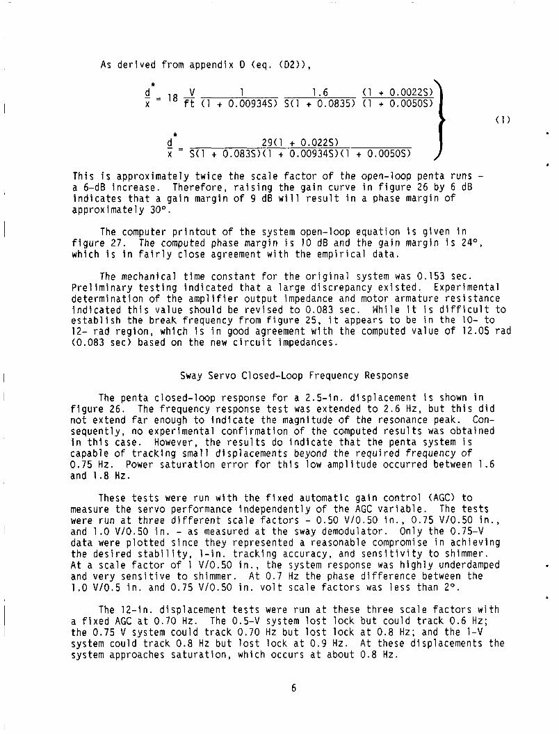
As d e r i v e d from appendix D (eq . (D2)) ,
* \ - - d - V 1 1 .6 ( 1 + 0.0022s) X - l8 ft ( 1 + 0.00934s) S ( l + 0.0835) ( 1 + 0.0050S)
* - d 29(1 + 0.022s) X = S ( l + O.O83S>(1 + O.O0934S>(l + 0.005OS)
( 1 )
. Th is i s a p p r o x i m a t e l y t w i c e t h e s c a l e f a c t o r o f t h e open- loop pen ta runs - a 6-dB i n c r e a s e . T h e r e f o r e , r a i s i n g t h e g a i n cu rve i n f i g u r e 26 by 6 dB i n d i c a t e s t h a t a g a i n marg in o f 9 dB w i l l r e s u l t i n a phase marg in of a p p r o x i m a t e l y 30°.
The computer p r i n t o u t o f t h e s y s t e m open- loop e q u a t i o n i s g f i g u r e 27. The computed phase marg in i s 10 dB and t h e g a i n marg which i s i n f a i r l y c l o s e agreement w i t h t h e e m p i r i c a l da ta .
The mechanical t i m e c o n s t a n t f o r t h e o r i g i n a l s y s t e m was 0.
ven i n n i s 24O,
53 sec. P r e l i m i n a r y t e s t i n g i n d i c a t e d t h a t a l a r g e d i s c r e p a n c y e x i s t e d . Exper imenta l d e t e r m i n a t i o n o f t h e a m o l i f i e r o u t w t imoedance and motor armature r e s s tance
c u l t t o 0- t o 2.05 r a d
i n d i c a t e d t h i s v a l u e shou ld be r e v j s e d to 0.083 sec. e s t a b l i s h t h e b reak f r e q u e n c y from f i g u r e 25, i t appears t o be i n the 12- r a d r e g i o n , which i s i n good agreement w i t h t h e computed v a l u e of (0.083 sec) based on t h e new c i r c u i t impedances.
Whi le i t i s d i f f
Sway Servo Closed-Loop Frequency Response
The p e n t a c l o s e d - l o o p response fo r a 2 . 5 - i n . d i sp lacemen t i s shown i n f i g u r e 26. The f requency response t e s t was extended to 2.6 Hz, b u t t h i s d i d n o t ex tend f a r enough to i n d i c a t e t h e magnitude o f t he resonance peak. Con- s e q u e n t l y , no e x p e r i m e n t a l c o n f i r m a t i o n o f t h e computed r e s u l t s was o b t a i n e d i n t h i s case. However, t h e r e s u l t s do i n d i c a t e t h a t t h e pen ta system i s capable o f t r a c k i n g sma l l d i sp lacemen ts beyond t h e r e q u i r e d f requency of 0.75 Hz. Power s a t u r a t i o n e r r o r f o r t h i s low a m p l i t u d e o c c u r r e d between 1.6 and 1.8 Hz.
These t e s t s were r u n w i t h t h e f i x e d a u t o m a t i c g a i n c o n t r o l (AGC) to measure t h e s e r v o per fo rmance i n d e p e n d e n t l y o f t h e AGC v a r i a b l e . were r u n a t t h r e e d i f f e r e n t s c a l e f a c t o r s - 0.50 V/0.50 i n . , 0.75 V/O.50 i n . , and 1.0 V/0.50 i n . - as measured a t t h e sway demodulator . On ly t h e 0.75-V d a t a w e r e p l o t t e d s i n c e t h e y r e p r e s e n t e d a reasonab le compromise i n a c h i e v i n g t h e d e s i r e d s t a b i l i t y , 1 - i n . t r a c k i n g accuracy, and s e n s i t i v i t y t o shimmer. A t a s c a l e f a c t o r o f 1 V/0.50 i n . , t h e system response was h i g h l y underdamped and v e r y s e n s i t i v e t o shimmer. 1.0 V / O . 5 i n . and 0.75 V / O . 5 0 i n . v o l t s c a l e f a c t o r s was l e s s t han 2 O .
The t e s t s
A t 0.7 Hz t h e phase d i f f e r e n c e between t h e .
The 12- in . d i sp lacemen t t e s t s w e r e r u n a t these t h r e e s c a l e f a c t o r s w i t h a f i x e d AGC a t 0.70 Hz. The 0.5-V system l o s t l o c k b u t c o u l d t r a c k 0 . 6 Hz; t h e 0.75 V s y s t e m c o u l d t r a c k 0.70 Hz b u t l o s t l o c k a t 0 . 8 Hz; and t h e 1-V s y s t e m c o u l d t r a c k 0.8 Hz b u t l o s t l o c k a t 0.9 Hz. A t these d i sp lacemen ts t h e system approaches s a t u r a t i o n , which occu rs a t about 0.8 Hz.
6
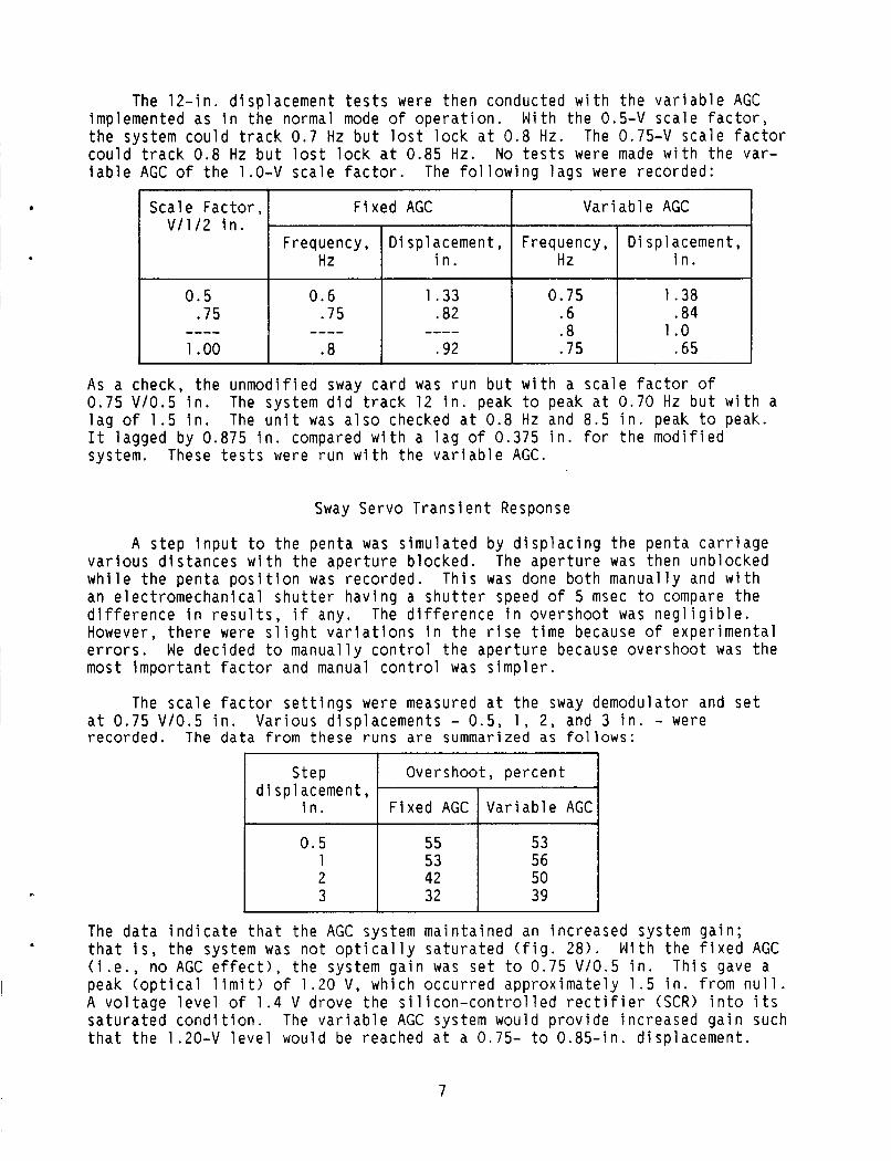
Sca le F a c t o r , V /1 /2 i n .
0 .5 .75
1 .oo ----
The 1 2 - i n . d i sp lacemen t t e s t s were t h e n conducted w i t h t h e v a r i a b l e AGC implemented as i n t h e normal mode o f o p e r a t i o n . Wi th the 0.5-V s c a l e f a c t o r , t h e system c o u l d t r a c k 0 .7 Hz b u t l os t l o c k a t 0.8 Hz. c o u l d t r a c k 0 . 8 Hz b u t l os t l o c k a t 0.85 Hz. No t e s t s were made w i t h t h e va r - i a b l e AGC o f t h e 1.0-V s c a l e f a c t o r . The f o l l o w i n g l a g s were reco rded :
The 0.75-V s c a l e f a c t o r
F i x e d AGC V a r i a b l e AGC I
Frequency, D isp lacement , Frequency, D isp lacement , Hz i n . Hz i n .
0.6 1.33 0.75 1.38 .75 .82 .6 .84
.8 .92 .75 .65 ---- .8 1 .o ----
0 . 5 1 2
I 3
As a check, t h e u n m o d i f i e d sway c a r d was r u n b u t w i t h a s c a l e f a c t o r o f 0.75 V l0 .5 i n . l a g o f 1.5 i n . The u n i t was a l s o checked a t 0.8 Hz and 8 .5 i n . peak to peak. I t lagged by 0.875 i n . compared w i t h a l a g o f 0.375 i n . f o r t h e m o d i f i e d system.
The system d i d t r a c k 12 i n . peak t o peak a t 0.70 Hz b u t w i t h a
These t e s t s were r u n w i t h t h e v a r i a b l e AGC.
55 53 53 56 42 50 32 39
Sway Servo T r a n s i e n t Response
A s t e p i n p u t t o t h e p e n t a was s i m u l a t e d by d i s p l a c i n g t h e pen ta c a r r i a g e The a p e r t u r e was then unb locked v a r i o u s d i s t a n c e s w i t h t h e a p e r t u r e b locked .
w h i l e t h e p e n t a p o s i t i o n was reco rded . T h i s was done b o t h manua l l y and w i t h an e l e c t r o m e c h a n i c a l s h u t t e r h a v i n g a s h u t t e r speed o f 5 msec t o compare t h e d i f f e r e n c e i n r e s u l t s , i f any. The d i f f e r e n c e i n ove rshoo t was n e g l i g i b l e . However, t h e r e were s l i g h t v a r i a t i o n s i n t h e r i s e t i m e because o f exper imen ta l e r r o r s . We dec ided t o manua l l y c o n t r o l t h e a p e r t u r e because o v e r s h o o t was t h e most i m p o r t a n t f a c t o r and manual c o n t r o l was s i m p l e r .
The s c a l e f a c t o r s e t t i n g s were measured a t t h e sway demodulator and s e t a t 0.75 V l 0 . 5 i n . Va r ious d i sp lacemen ts - 0 .5 , 1 , 2, and 3 i n . - were reco rded . The d a t a from these r u n s a r e summarized as fo l lows:
Overshoot , p e r c e n t d i s p l acement,
i n .
The d a t a i n d i c a t e t h a t t h e AGC system m a i n t a i n e d an i n c r e a s e d system g a i n ; t h a t i s , t h e system was n o t o p t i c a l l y s a t u r a t e d ( f i g . 28) . W i th t h e f i x e d AGC ( i . e . , no AGC e f f e c t ) , t h e system g a i n was s e t t o 0 .75 V l 0 . 5 i n . T h i s gave a peak ( o p t c a l l i m i t ) o f 1.20 V, wh ich o c c u r r e d a p p r o x i m a t e l y 1 . 5 i n . from n u l l . A v o l t a g e l e v e l o f 1 .4 V d rove t h e s i l i c o n - c o n t r o l l e d r e c t i f i e r (SCR) i n t o i t s s a t u r a t e d c o n d i t i o n . The v a r i a b l e AGC system would p r o v i d e i n c r e a s e d g a i n such t h a t t h e .20-V l e v e l would be reached a t a 0.75- t o 0 .85 - in . d i sp lacemen t .
7
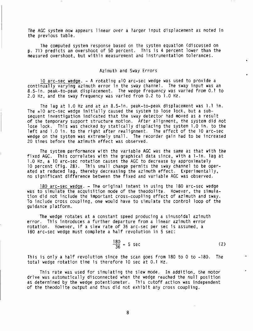
The AGC s y s t e m now appears l i n e a r o v e r a l a r g e r i n p u t d isp lacement as n o t e d i n t h e p r e v i o u s t a b l e .
The computed system response based on t h e system e q u a t i o n (d i scussed on p. 7 1 ) p r e d i c t s an o v e r s h o o t o f 50 p e r c e n t . Th i s i s 4 p e r c e n t lower than t h e measured ove rshoo t , b u t w i t h i n measurement and i n s t r u m e n t a t i o n t o l e r a n c e s .
Azimuth and Sway Errors
10 arc-sec wedge. - A r o t a t i n g 210 arc-sec wedge was used t o p r o v i d e a c o n t i n u a l l y v a r y i n g az imu th error i n t h e sway channel . 8 . 5 - i n . peak-to-peak d i sp lacemen t . The wedge f requency was v a r i e d from 0.1 to 2.0 Hz, and t h e sway f r e q u e n c y was v a r i e d from 0.2 t o 1.0 Hz.
The sway i n p u t was an
The l a g a t 1.0 Hz and a t an 8 . 5 - i n . peak-to-peak d isp lacement was 1 . 1 i n . The 210 arc-sec wedge i n i t i a l l y caused t h e system t o lose l o c k , b u t a sub- sequent i n v e s t i g a t i o n i n d i c a t e d t h a t t he sway d e t e c t o r had moved as a r e s u l t o f t h e temporary suppor t s t r u c t u r e mo t ion . A f t e r a l i gnmen t , t he s y s t e m d i d n o t lose l o c k . T h i s was checked by s t a t i c a l l y d i s p l a c i n g t h e sys tem 1.0 i n . t o t h e l e f t and 1.0 i n . t o t h e r i g h t a f t e r r e a l i g n m e n t . The e f f e c t of t h e 10 arc-sec wedge on t h e system was e x t r e m e l y s m a l l . The r e c o r d e r g a i n had t o be i n c r e a s e d 20 t i m e s b e f o r e t h e az imu th e f f e c t was observed.
The sys tem performance w i t h t h e v a r i a b l e AGC was the same as t h a t w i t h t h e f i x e d AGC. T h i s c o r r e l a t e s w i t h t h e g r a p h i c a l d a t a s i n c e , w i t h a 1 - i n . l a g a t 1.0 Hz, a 10 arc-sec r o t a t i o n causes t h e AGC t o decrease by a p p r o x i m a t e l y 10 p e r c e n t ( f i g . 28) . T h i s smal l change p e r m i t s t h e sway channel t o be oper- a t e d a t reduced l a g , t h e r e b y d e c r e a s i n g t h e az imuth e f f e c t . E x p e r i m e n t a l l y , no s i g n i f i c a n t d i f f e r e n c e between t h e f i x e d and v a r i a b l e AGC was observed.
180 arc-sec wedge. - The o r i g i n a l i n t e n t i n u s i n g t h e 180 arc-sec wedge was t o s i m u l a t e t h e a c q u i s i t i o n mode o f t h e t h e o d o l i t e . However, t h e s imula- t i o n d i d n o t i n c l u d e t h e i m p o r t a n t c r o s s - c o u p l i n g e f f e c t o f az imu th and sway. To i n c l u d e c r o s s c o u p l i n g , one would have t o s i m u l a t e t h e c o n t r o l l o o p of t h e guidance p l a t f o r m .
The wedge r o t a t e s a t a c o n s t a n t speed p r o d u c i n g a s i n u s o i d a l az imu th er ror . T h i s i n t r o d u c e s a f u r t h e r d e p a r t u r e from a l i n e a r az imu th error r o t a t i o n . However, i f a s l e w r a t e o f 36 arc-sec p e r sec i s assumed, a 180 arc-sec wedge must complete a h a l f r e v o l u t i o n i n 5 sec:
!$j = 5 sec ( 2 )
T h i s i s o n l y a h a l f r e v o l u t i o n s i n c e t h e scan goes from 180 t o 0 to -180. The t o t a l wedge r o t a t i o n t i m e i s t h e r e f o r e 10 s e c a t 0.1 Hz.
T h i s r a t e was used f o r s i m u l a t i n g t h e s l e w mode. I n a d d i t i o n , t h e motor d r i v e was a u t o m a t i c a l l y d i sconnec ted when t h e wedge reached t h e n u l l p o s i t i o n as determined by t h e wedge p o t e n t i o m e t e r . Th i s c u t o f f a c t i o n was independent of t h e t h e o d o l i t e o u t p u t and thus d i d n o t e x h i b i t any cross c o u p l i n g .
8

The sway s e r v o was never a b l e t o a c q u i r e system a t t h e f irst s i g n a l appearance i n t h e sway channel . I t i n v a r i a b l y passed t h r o u g h t h e a c t i v e r e g i o n t h r e e t o f o u r t i m e s b e f o r e i t a c q u i r e d t h e P o r r o p r i s m and n u l l e d i t s e l f , b u t by t h i s t i m e t h e wedge r o t a t i o n had stopped and t h e az imu th error was z e r o . The system was, however, a b l e t o a c q u i r e t h e Porro p r i s m a f t e r t h e az imu th c y c l e ; t h a t i s , d u r i n g t h e combined sway-azimuth c y c l e i t would always r e a c q u i r e t h e Porro p r i s m .
Sys tem s i m u l a t i o n t e s t s . - T e s t s were r u n u s i n g t h e 180 arc-sec wedge t o s i m u l a t e as c l o s e l y as p o s s i b l e c losed- loop sway o p e r a t i o n . The f i r s t t e s t was r u n w i t h b o t h ;way systems d i s a b l e d and w i t h t h e wedge c o n t i n u o u s l y r o t a t i n g , d i s p l a c i n g t h e p e n t a mi r ror . mirror sway s e r v o o p e r a t i n g and t h e wedge c y c l i n g and then s t o p p i n g a t t h e error n u l l . The f i n a l s e r i e s o f t e s t s w e r e made w i t h t h e sway s i m u l a t o r o p e r a t i n g a t an 8 . 5 - i n . peak-to-peak d i sp lacemen t and a 0.8-Hz f requency , t h e p e n t a m i r r o r s e r v o o p e r a t i n g , and t h e wedge r o t a t i n g th rough one c y c l e t o n u l l . Data i n d i c a t e d t h a t t h e p e n t a mirror f i n a l l y l o c k s on a f t e r t h r e e c y c l e s o f t h e s i m u l a t o r .
The n e x t t e s t was r u n w i t h t h e pen ta
Shimmer e f f e c t s . - Two d a t a r u n s were taken t o i n d i c a t e t h e e f f e c t o f shimmer on a f a i r l y t y p i c a l bad day: t h a t i s , a b r i q h t , sunny day. One r u n was t a k e n to i n d i c a t e - t h e e f f e c t of changes i n g a i n ( g a i n s o f - 0 . 5 - V / 0 . 5 i n . and 0.75 V/0.5 i n . ) . Data i n d i c a t e d t h a t t h e h i g h e r g a i n c o n t a i n e d h i g h e r f requency components and l a r g e r peak d isp lacements o f up t o 0 .25 i n . Data from a second r u n i n d i c a t e d t h a t compensation networks reduce t h e bandwidth o f t h e servo sys tem (wh ich i s s e t by t h e ne twork ) , n o t t h e mechanical system.
System L i m i t a t i o n
S a t u r a t i o n . - The o r i g i n a l sway se rvo s y s t e m was a b l e t o t r a c k a 1 2 - i n . peak-to-peak d i sp lacemen t a t 0.75 Hz w i t h l e s s than a 1 - i n . l a g . However, t h e sys tem was n o t a b l e t o t r a c k beyond 0.85 Hz w i t h o u t l o s i n g l o c k .
For s m a l l e r d i sp lacemen ts (2 .5 i n . ) t h e sway s e r v o was a b l e t o t r a c k t h e t a r g e t beyond 4.0 Hz. T h i s i n d i c a t e d t h a t t h e o r i g i n a l s y s t e m was power l i m i t e d when t r a c k i n g a 12 - in . d i sp lacemen t a t f r e q u e n c i e s beyond 0.7 Hz. The s i m u l a t o r s e r v o c o n s i s t e d o f a s i m i l a r SCR d r i v e and motor b u t used a h i g h e r v o l t a g e power t r a n s f o r m e r for t h e S C R ' s . The s i m u l a t o r was t e s t e d up t o 1.4 Hz a t a 12 - in . peak-to-peak d i sp lacemen t . I t i s p r o b a b l y capable o f a h i g h e r power o u t p u t , b u t i t i s l i m i t e d by t h e v o l t a g e d rop due t o t h e l o n g power l i n e from t h e v o l t a g e source. 20 V under t h e f u l l l o a d c o n d i t i o n s o f a 12 - in . d i sp lacemen t and a 1.0- t o 1.4-Hz f requency .
The v o l t a g e a t t h e s i m u l a t o r dropped by
Thermal l i m i t a t i o n s . - The thermal l i m i t a t i o n was s e t by t h e SCR power t r a n s f o r m e r , which has a 300-V-A r a t i n g . D u r i n g t e s t s o f t h e sway se rvo , t h e t r a n s f o r m e r underwent a h i g h e r temperature r i s e than t h e motor. The s i m u l a t o r . servo, however, had a 500-V-A t rans fo rmer which r e p l a c e d t h e 300-V-A t r a n s - fo rmer ; The motor and t r a n s f o r m e r i n t h e s i m u l a t o r had a p p r o x i m a t e l y equiva- l e n t t empera tu re r i s e s . I n a d d i t i o n , t he motor was n o t capable o f d i s s i p a t i n g t h e h e a t generated under a 12 - in . , 0.75-Hz c o n d i t i o n fo r an extended p e r i o d . Pages 73 t o 75 o f appendix D c o n t a i n a d i s c u s s i o n o f these l i m i t a t i o n s .
9
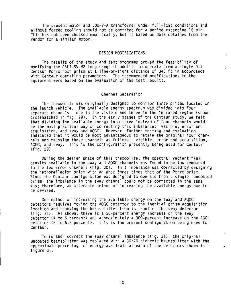
The p r e s e n t motor and 500-V-A t rans fo rmer under f u l l - l o a d c o n d i t i o n s and w i t h o u t f o r c e d c o o l i n g shou ld n o t be o p e r a t e d f o r a p e r i o d exceed ing 10 min . T h i s has n o t been checked e m p i r i c a l l y , b u t i s based on d a t a o b t a i n e d from t h e vendor f o r a s i m i l a r motor.
D E S I G N M O D I F I C A T I O N S
The r e s u l t s o f t h e s t u d y and t e s t programs p roved t h e f e a s i b i l i t y o f m o d i f y i n g t h e AALT-SV-M2 long-range t h e o d o l i t e t o o p e r a t e from a s i n g l e D-1 Centaur Porro roof p r i s m a t a l i n e - o f - s i g h t d i s t a n c e o f 345 f t i n accordance w i t h Centaur o p e r a t i n g parameters . The recommended m o d i f i c a t i o n s t o t h e equipment were based on t h e e v a l u a t i o n o f t h e t e s t r e s u l t s .
Channel S e p a r a t i o n
The t h e o d o l i t e was o r i g i n a l l y designed t o m o n i t o r t h r e e p r i sms l o c a t e d on t h e launch v e h i c l e . The a v a i l a b l e energy spec t rum was d i v i d e d i n t o f o u r separa te channels - one i n t h e v i s i b l e and t h r e e i n t h e i n f r a r e d r e g i o n (shown c rosshatched i n f i g . 2 9 ) . I n t h e e a r l y s tages o f t h e Centaur s tudy , we f e l t t h a t d i v i d i n g t h e a v a i l a b l e energy i n t o t h r e e i n s t e a d o f f o u r channe ls would be t h e most p r a c t i c a l way o f c o r r e c t i n g t h i s imba lance: v i s i b l e , e r r o r and a c q u i s i t i o n , and sway and AQGC. However, f u r t h e r t e s t i n g and e v a l u a t i o n i n d i c a t e d t h a t i t would be most advantageous t o r e t a i n t h e o r i g i n a l f o u r chan- n e l s and r e a s s i g n these channe ls as follows: v i s i b l e , e r r o r and a c q u i s i t i o n , AQGC, and sway. T h i s i s t h e c o n f i g u r a t i o n p r e s e n t l y b e i n g used for Cen tau r ( f i g . 29 ) .
D u r i n g t h e d e s i g n phase of t h i s t h e o d o l i t e , t h e s p e c t r a l r a d i a n t f l u x d e n s i t y a v a i l a b l e i n t h e sway and AQGC channe ls was found t o be low compared t o t h e two error channe ls ( f i g . 30). T h i s imba lance was c o r r e c t e d by d e s i g n i n g t h e r e t r o r e f l e c t o r p r i s m w i t h an a r e a t h r e e t imes t h a t o f t h e Porro p r i s m . S ince t h e Centaur c o n f i g u r a t i o n was des igned t o o p e r a t e from a s i n g l e , uncoated p r i sm, t h e imbalance i n t h e sway channel c o u l d n o t be c o r r e c t e d i n t h e same way; t h e r e f o r e , an a l t e r n a t e method of i n c r e a s i n g t h e a v a i l a b l e energy had to be dev i sed .
One method o f i n c r e a s i n g t h e a v a i l a b l e energy on t h e sway and AQGC d e t e c t o r s r e q u i r e s moving t h e AQGC d e t e c t o r t o t h e i n e r t i a l p r i s m a c q u i s i t i o n l o c a t i o n and removing t h e b e a m s p l i t t e r from i n f r o n t o f t h e sway d e t e c t o r ( f i g . 31) . A s shown, t h e r e i s a 50-percent energy i n c r e a s e on t h e sway d e t e c t o r ( 4 t o 6 p e r c e n t ) and a p p r o x i m a t e l y a 300-percent i n c r e a s e on t h e AGC d e t e c t o r ( 2 t o 6.5 p e r c e n t ) . T h i s i s t h e p r e s e n t c o n f i g u r a t i o n b e i n g used fo r Centaur .
To f u r t h e r c o r r e c t t h e sway channel imbalance ( f i g . 31 ) , t h e o r i g i n a l uncoated b e a m s p l i t t e r was r e p l a c e d w i t h a 30:70 d i c h r o i c b e a m s p l i t t e r w i t h t h e approx imate percentage o f energy a v a i l a b l e a t each o f t h e d e t e c t o r s shown i n f i g u r e 31.
.
10

A u t o c o l l i m a t o r
The m o d i f i c a t i o n s t o t h e a u t o c o l l i m a t o r were l o c a t e d m a i n l y i n t h e source and d e t e c t o r assembly. s p e c t r a l s e p a r a t i o n scheme as shown i n f i g u r e 29. Transmiss ion p l o t s o f t h e v a r i o u s f i l t e r s and b e a m s p l i t t e r a r e shown i n f i g u r e s 32 t o 37. A s i m p l i f i e d
O the r m o d i f i c a t i o n s were as fo l lows:
These changes w e r e t h e r e s u l t s o f r e a r r a n g i n g t h e
0 o p t i c a l schematic o f t h e source and d e t e c t o r assembly i s shown i n f i g u r e 39.
b ( 1 ) The sway d e t e c t o r remained unchanged w i t h t h e e x c e p t i o n o f add ing a x 1 r e i m a g i n g l e n s .
( 2 ) The AQGC d e t e c t o r c o n f i g u r a t i o n was changed by i n c r e a s i n g t h e c e n t r a l dead zone from 0 .1 to 1.27 mm.
(3) The uncoated b e a m s p l i t t e r was r e p l a c e d w i t h a 30:70 d i c h r o i c beam- s p l i t t e r as noted p r e v i o u s l y .
(4) The a c q u i s i t i o n d e t e c t o r was redes igned as a s p l i t d e t e c t o r t h a t was i d e n t i c a l t o t h e AQGC d e t e c t o r .
(5) The AGC d e t e c t o r was r e l o c a t e d ( f i g . 39) t o r e t a i n t h e o r i g i n a l x 2.5 m a g n i f i c a t i o n c o n f i g u r a t i o n .
(6) The e l e c t r o n i c components were reworked; t h a t i s , t hose components t h a t were no l o n g e r needed were removed.
(7) An e x t e r n a l t u r n mirror r e s e t was i n c o r p o r a t e d . The o r i g i n a l d e s i g n was such t h a t , when s w i t c h i n g back to t h e p r i m a r y lamp from t h e redundan t lamp, t h e o u t e r cover and then a smal l cove r on t h e source and t h e d e t e c t o r cove r had t o be removed t o a l l o w a s c r e w d r i v e r t o be i n s e r t e d i n t o t h e t u r n mirror s h a f t to r o t a t e t h i s s h a f t . T h i s method was n o t o n l y t i m e consuming b u t made i t p o s s i b l e f o r t h e s c r e w d r i v e r t o s l i p and damage t h e mirror c o a t i n g .
(8) Lamp v o l t a g e was reduced t o 4.7 V , t hus a l l o w i n g t h e lamp t o o p e r a t e a t 2400-K c o l o r t empera tu re and e x t e n d i n g i t s i t s l i f e (9000 h r o f l i f e com- pared t o the original 6.7 V which gave 120 hr o f life).
D i s p l a y Panel
The changes t o t h e d
( 1 ) The sway s i g n a l nected, t h u s changing t h e
(2) The DC a m p l i f i e r 4
s p l a y panel were as f o l l o w s :
npu t to t h e sway l o g i c c o n t r o l u n i t was d i scon - sway a c q u i s i t i o n f u n c t i o n to AQGC a c q u i s i t i o n .
was m o d i f i e d t o i n c r e a s e t h e system s c a l e f a c t o r from 100 t o 200 mV/arc-sec, t hus r e d u c i n g t h e o u t p u t s i g n a l impedance.
The d iodes w e r e needed t o p r e v e n t t h e o p e r a t i o n a l a m p l i f i e r from b e i n g o v e r d r i v e n .
(3) The a c q u i s i t i o n a m p l i f i e r was m o d i f i e d i n accordance w i t h f i g u r e 24.
1 1

( 4 ) The a c q u i s i t i o n r e l a y d r i v e r was m o d i f s y s t e m o p e r a t i n g s c a l e f a c t o r was changed ( i t e m t h i s ca rd a l s o i nc reased . Th is e r r o r s i g n a l i s r e l a y and t u r n on t h e a c q u i s i t i o n l i g h t .
Sway Servo Assemt
ed as i n f i g u r e 24. S ince t h e ( 2 > > , t h e e r r o r s i g n a l i n p u t t o used t o a c t u a t e t h e a c q u i s i t i o n
The changes t o t h e sway s e r v o assembly were as fol lows:
( 1 ) The sway se rvo d r i v e c a r d was m o d i f i e d so t h e system c o u l d t r a c k p r i s m
( 2 ) The 300-V-A t rans fo rmer was r e p l a c e d w i t h a h i g h e r wa t tage (500 V-A)
sway o f 12- in . peak-to-peak d i sp lacemen t a t 0 .75 Hz.
u n i t .
( 3 ) The sway se rvo covers were m o d i f i e d t o i n c o r p o r a t e a f a n and d u c t s f o r c o o l i n g the t r a n s f o r m e r and motor.
An e l e c t r o n i c b l o c k d iagram of t h e Centaur system i s shown i n f i g u r e 40.
CONCLUDING REMARKS
The AALT-M2 long-range t h e o d o l i t e was des igned and b u i l t by Perk in -E lmer C o r p o r a t i o n t o s i m u l t a n e o u s l y b u t s e p a r a t e l y m o n i t o r t h e a l i g n m e n t o f an i n e r t i a l p l a t f o r m p r i s m and t r a c k t h e sway p r i sms l o c a t e d on t h e s k i n o f t h e launch v e h i c l e s a t l i n e - o f - s i g h t d i s t a n c e s up to 850 f t .
One o f these u n i t s (GFE) was t e s t e d a t Perk in -E lmer t o d e t e r m i n e t h e f e a s i b i l i t y of mod i f y ing t h e system t o enab le i t t o o p e r a t e from a s i n g l e D-1 Centaur roof p r i s m a t a s h o r t e r l i n e - o f - s i g h t range o f 325 f t. formed and t h e r e s u l t s documented i n t h e r e p o r t show t h a t t h e system can be m o d i f i e d , as s p e c i f i c a l l y d e s c r i b e d i n t h i s r e p o r t , and meet t h e Centaur system requ i remen ts .
The t e s t s p e r -
For reuse on Complex 41 ( T i t an /Cen tau r DOD usage), t h e a u t o t h e o d o l i t e w i l l r e q u i r e m o d i f i c a t i o n and p r i s m ad jus tmen ts because o f t h e s h o r t l i n e o f s i g h t a v a i l a b l e (-325 f t ) and w i l l r e q u i r e a new e l e v a t i o n h e i g h t f o r t h e t h e o d o l i t e . Shimmer and a m p l i f i e r s a t u r a t i o n w i l l i n a l l p r o b a b i l i t y be t h e major problem a r e a because of t h e s h o r t l i n e o f s i g h t .
Also, i n t h e even t t h a t t o DOD dec ides t o e l i m i n a t e t h e need f o r t h e au to- t h e o d o l i t e a t Complex 41 and t o u t i l i z e gyrocompassing (as t h a t p roposed for S h u t t l e / C e n t a u r ) for az imu th a l i g n m e n t of C e n t a u r ' s i n e r t i a l p l a t f o r m , a word o f c a u t i o n i s i n o r d e r . W i th gyrocompassing, az imu th a l i g n m e n t e r r o r s a r e on the o r d e r o f a rc -minu tes , whereas w i t h t h e a u t o t h e o d o l i t e sys tem, az imu th e r r o r s a re on t h e o r d e r of arc-seconds. requ i rement , gyrocompassing error s e n s i t i v i t y w i l l a f f e c t t h e i n j e c t i o n accuracy o f t h e m i s s i o n .
Depending on t h e m i s s i o n accu racy
c
12

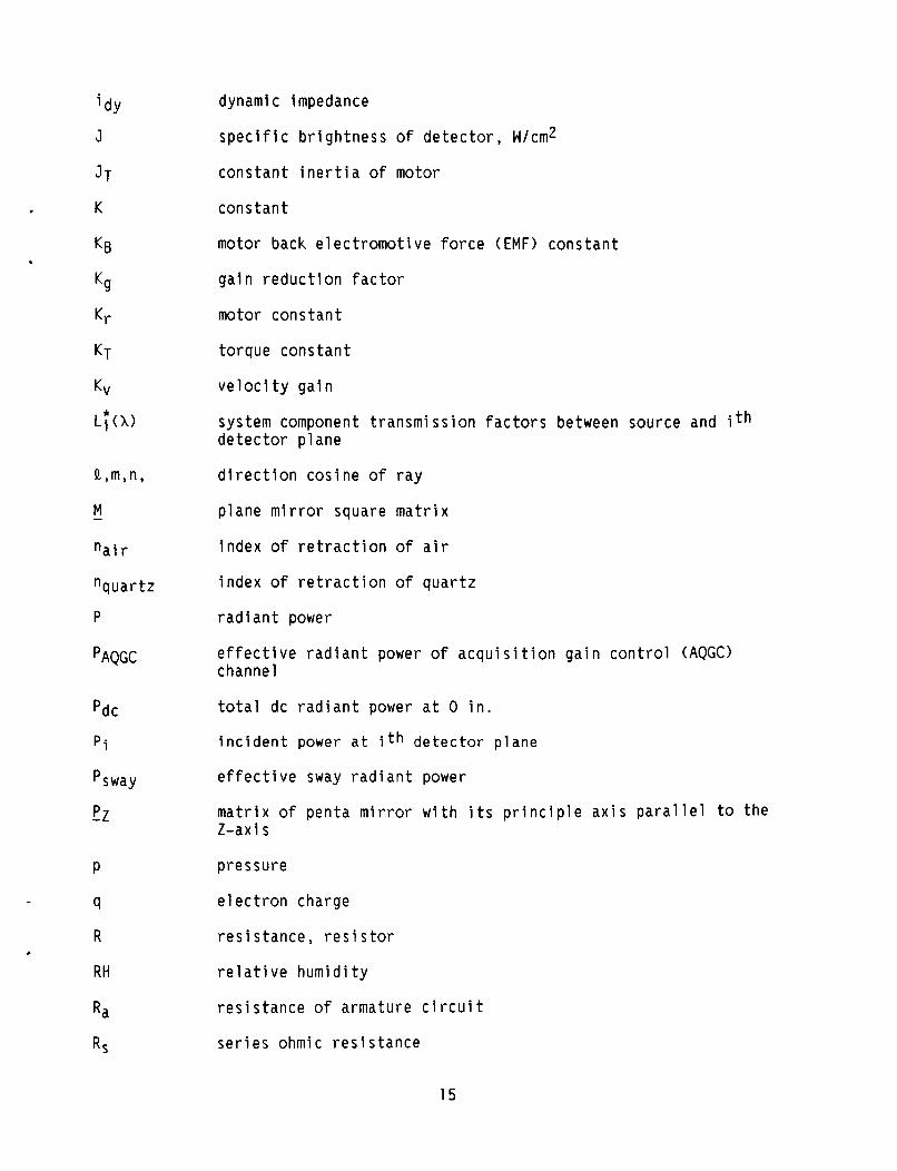
APPENDIX A SYMBOLS
A area
A(X) atmospheric transmission with respect to wavelength
Ae r
Ai
Apr i
AS area of sway detector
projected area of source for error channel
projected area of source at ith detector plane
area of ith prism
Asway* AQGC projected area of source for sway and acquisition gain control (AQGC) channels
- A autocollimatpr matrix
A* attenuation ratio
C
B*
D
D* *
Dnorm(1)
d A
return image matrix
direction cosines of unit directed outward from reflecting surface
capaci tor
Boltzmann's constant
density of water vapor
detectivi ty
normalized detectivity of detectors with respect to wavelength
autocollimator aperture
dl ens
d 0 operating distance
autocollimator objective lens diameter
dpen penta position
d*
E voltage drop
EAMGC amplifier gain control (AMGC) control voltage
feedback at penta mirror position
Ea
EB bias voltage applied across cell and load resistor
voltage applied to motor armature
13

E*
E ' (1)
F T
f
f / n o
h
hum
I
I s i g
I*
e l e v a t i o n a n g l e
tungs ten e m i s s i v i t y w i t h r e s p e c t t o wavelength
i n p u t s i g n a l
dc o u t p u t s i g n a l
v o l t a g e o f s i g n a l
o u t p u t of t h e o d o l i t e
s i g n a l o u t p u t v o l t a g e i n rms
v i s c o u s f r i c t i o n l o a d
d i c h r o i c f i 1 t e r t r a n s m i s s i o n f a c t o r s between source and i t h d e t e c t o r p l a n e , w i t h r e s p e c t t o wave length
4 motor c o n s t a n t
t h e o d o l i t e f o c a l l e n g t h
f-number o f o b j e c t i v e l e n s ; f o c a l l e n g t h d i v i d e d by average d iamete r
f requency
s y s t e m e l e c t r i c a l bandwidth
motor and l o a d t r a n s f e r f u n c t i o n
geomet r i c r a y v e c t o r square m a t r i x
r e f l e c t e d r a y
g a i n
h e i g h t
e f f e c t i v e s p e c t r a l r a d i a n t f l u x d e n s i t y w i t h r e s p e c t t o wave- l e n g t h and c o l o r t empera tu re
s p e c t r a l r a d i a n t f l u x d e n s i t y w i t h r e s p e c t t o wave length
image h e i g h t
h u m i d i t y
c u r r e n t
maximum s i g n a l w i t h an a m p l i f i e r g a i n c o n t r o l v o l t a g e o f 10 V
l i g h t i n t e n s i t y
14
dy
J
JT
K
KB
Kg
K r
KT
K V
L Y W
Q,m,n,
M
n a i r
n q u a r t z
P
-
PAQGC
pdc
P i
Psway
-2 P
P
q
R
RH
Ra
RS
dynami c impedance
s p e c i f i c b r i g h t n e s s o f d e t e c t o r , W/cm2
c o n s t a n t i n e r t i a o f motor
c o n s t a n t
motor back e l e c t r o m o t i v e f o r c e (EMF) c o n s t a n t
g a i n r e d u c t i o n f a c t o r
motor c o n s t a n t
t o r q u e c o n s t a n t
v e l o c i t y g a i n
system component t r a n s m i s s i o n f a c t o r s between source and i th d e t e c t o r p l a n e
d i r e c t i o n c o s i n e o f r a y
p lane mirror square m a t r i x
index o f r e t r a c t i o n o f a i r
i ndex o f r e t r a c t i o n o f q u a r t z
r a d i a n t power
e f f e c t i v e r a d i a n t power o f a c q u i s i t i o n g a i n c o n t r o l (AQGC) c hanne 1
t o t a l dc r a d i a n t power a t 0 i n .
i n c i d e n t power a t i th d e t e c t o r p l a n e
e f f e c t i v e sway r a d i a n t power
m a t r i x o f p e n t a mirror w i t h i t s p r i n c i p l e a x i s p a r a l l e l t o t h e Z-axi s
pressu re
e l e c t r o n charge
r e s i s t a n c e , res i s to r
r e l a t i v e h u m i d i t y
r e s i s t a n c e o f armature c i r c u i t
s e r i e s ohmic r e s i s t a n c e

Rtot -x R
S
SCR
SIN
S*
S
Sref sw
Tab
Tam
TO T *
t
t D
U
V
-
V
Waca
WQ
Wvi g
x*y ,z
total resistance of armature circuit
roof prism matrix with its roof
Lap1 ace transform
silicon-controlled rectifier
s i gna 1 - to-no i se rat i o
specific responsivity of detector
sway or displacement
displacement or sway o f 3 in.
switch
absolute temperature ambient temperature
source color temperature
total transmittance
time
time domain
desired orthogonal rotation matrix
voltage
precipitable water vapor
width
effective spectral radiance of tungsten filament source
spectral radiance of source
black body brightness
width of image
equivalent width of acquisition return image
limiting width
width at which vignetting begins
coordinates
16

X input error signal (displacement, in.)
Y12A 1-28 1 2 ~ short circuit transfer admittance of input networks A,B, and C
Yn CCLS output on the nth cycle
ZOH zero-order hold
a angle between direction of radiation and normal to surface
B angular rotation of roof prism
E log o f constant
e penta lead screw displacement, rad
ecri t critical angle
ee azimuth misalignment reference error
emax maximum mirror angular travel that will return light to the autocollimator
guidance platform attitude, arc-sec
guidance platform drift, arc-sec/sec
etotal angular acquisition range
eref reference azimuth
x wavelength
Xcut long wavelength cutoff
5 damping ratio
P angular position of Porro prism
angle of rotation of the autocollimator return image about its center
CY' return image rotation angle
T response time constant
Telec motor electrical time constant
=me c h mechanical time constant
T* thermal time constant
Y demodular time constant
17
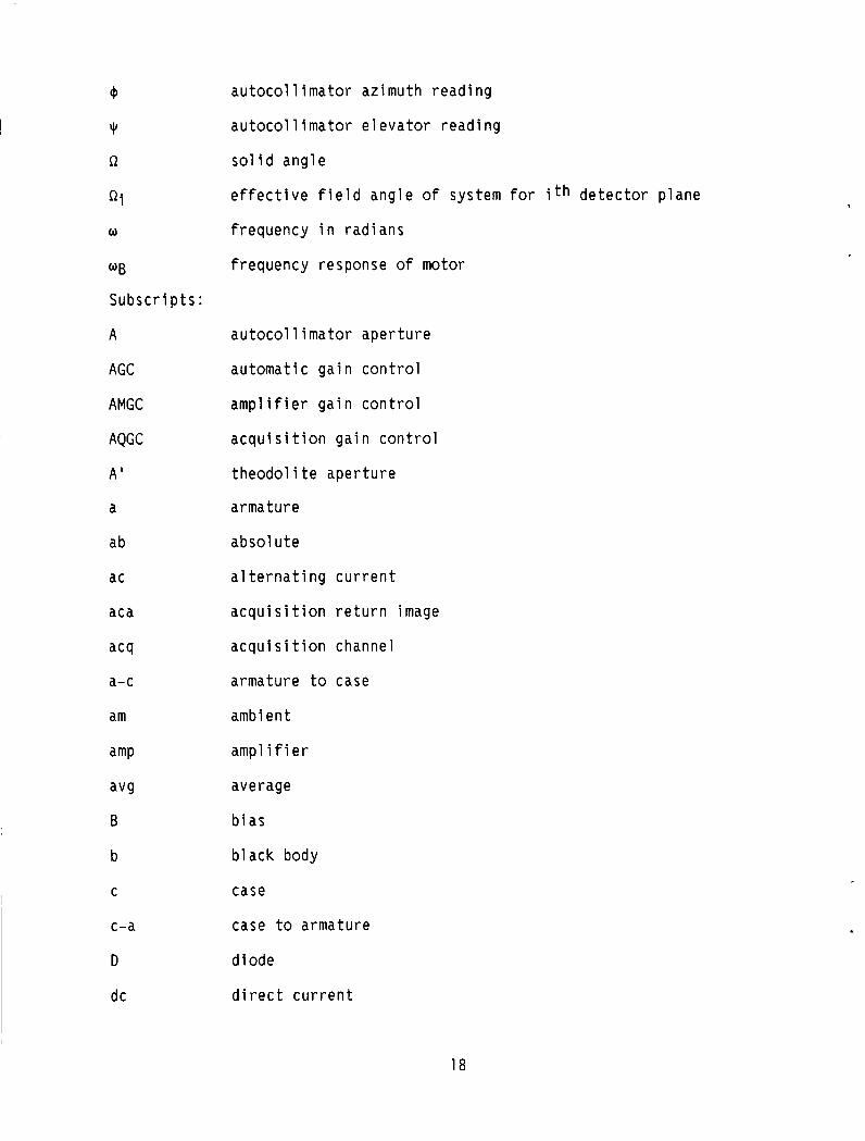
Q
Y
a
ai w
W B
Subscr i pts :
A
AGC
AMGC
AQGC
A '
a
ab
ac
aca
acq
a-c
am
amp
avg
B
b
C
c-a
D
dc
autocollimator azimuth reading
autocollimator elevator reading
solid angle
effective field angle of system for ith detector plane
frequency in radians
frequency response of motor
autocollimator aperture
automatic gain control
amplifier gain control
acquisition gain control
theodol i te aperture
armature
absol Ute
alternat ng current
acquisit on return image
acquisition channel
armature to case
ambient
amplifier
average
bias
black body
case
case to armature
diode
direct current
18

dY
e
e f f
e l e c
e r
error
f
g
I
i
i n
L
Q
m
max
mech
n
nose
norm
0
oc
o u t
P
Pen
P r
R
r e f
dynamic
response
e f f e c t i v e
e l e c t r i c a l
e r r o r channel
e r r o r
c o n t r o l
g a i n
c u r r e n t
i th pr i sm; i th d e t e c t o r p l a n e
i n p u t
1 oad
l i m i t i n g
motor
maxi mum
mechanica l
n t h
nose o f p r i s m
n o r m a l i z e d
o p e r a t i n g
open c i r c u i t
o u t p u t
p l a t f o r m
p e n t a
Porro p r i s m
res i s to r
r e f e r e n c e
19
rf 1
S
S
sig
sway
SY S
T
t
tot
tri
V
vi g
x,y,z
0
reflector
series
sway detector
signal
sway channel
sys tern
torque
theodol i te
total
trihedral pri srn
velocity
vignetting
coordinates
source
20

I n appendixes B, C, and D a r e t h e e n g i n e e r i n g d a t a and no tes taken from the a u t h o r ' s notebook. T h i s i n f o r m a t i o n was reco rded by t h e a u t h o r d u r i n g t h e t e s t i n g phase.
APPENDIX B LONG-RANGE, AUTOMATIC AZIMUTH-LAYING THEODOLITE
SYSTEM D E S I G N STUDY AND CONSIDERATIONS - FIGURES OF M E R I T (FOM)
The p r e d i c t e d per fo rmance o f t h e a u t o m a t i c a z i m u t h - l a y i n g t h e o d o l i t e (AALT) i s de termined by c a l c u l a t i n g t h e f i g u r e s o f m e r i t (FOM's) l i s t e d f o r t h e v a r i o u s channels as
( 1 ) Error Channels
(a ) Angu la r s e n s i t i v i t y , W/arc-sec (b ) S i g n a l - t o - n o i s e r a t i o ( S I N ) p e r arc-sec ( c ) Angu la r r e s o l u t i o n ( f o r u n i t y S / N >
( 2 ) A c q u i s i t i o n channe ls
( a ) Rad ian t f l u x a t e r r o r channel n u l l ( b ) S / N a t e r r o r channel n u l l
(3) Sway channel
( a ) E f f e c t i v e r a d i a n t f l u x a t 1 /16 - in . sway ( b ) S / N f o r 1 /16 - in . sway ( c ) Sway r e s o l u t i o n ( f o r u n i t y S I N ) , i n .
(4) Automat ic g a i n c o n t r o l (AGC) channel
( a ) Rad ian t f l u x
To c a l c u l a t e these q u a n t i t i e s , one must e v a l u a t e t h e f o l l o w i n g e q u a t i o n :
where
P i i n c i d e n t power a t i th d e t e c t o r p l a n e ( i t h channe l ) , W
A(X) a tmospher ic t r a n s m i s s i o n
L * i ( X > system component t r a n s m i s s i o n f a c t o r ( r e f l e c t i o n l o s s e s , e t c . ) f o r i t h channel
F * ( X ) d i c h r o i c f i 1 t e r t r a n s m i s s i o n f a c t o r s between source and i t h d e t e c t o r p lane
21
W:ff(X)
Dnorm(X) no rma l i zed d e t e c t i v i t y o f d e t e c t o r s
A i p r o j e c t e d a rea o f source a t i t h d e t e c t o r p lane
Qi e f f e c t i v e f i e l d ang le o f system fo r i t h d e t e c t o r p lane
S ince t h e AALT genera tes s i x o u t p u t s s imu l taneous ly , e q u a t i o n ( B 1 ) must be e v a l u a t e d s i x t imes , w i t h each c a l c u l a t i o n i n c l u d i n g the p a r t i c u l a r loss f a c t o r s and d i c h r o i c f i l t e r s f o r t h e channel b e i n g c a l c u l a t e d . I n a d d i t i o n , t h e r e s u l t s a r e n o n l i n e a r f u n c t i o n s f o r f o u r i m p o r t a n t o p e r a t i n g parameters - source c o l o r t empera tu re , o p e r a t i n g d i s t a n c e , ambient tempera ture , and ambient h u m i d i t y . Thus e q u a t i o n (B1) must be r e e v a l u a t e d i n i t s e n t i r e t y , s i x t imes , f o r any change i n these parameters .
Because t h e c a l c u l a t i o n f o r each channel and c h o i c e o f o p e r a t i n g para- meters i n v o l v e s t h e i n t e g r a t i o n o f t h e p r o d u c t o f app rox ima te l y e i g h t wave- l e n g t h te rms, Perk in -E lmer des igned a d i g i t a l computer program t o p e r f o r m these l e n g t h y compu ta t i ons .
e f f e c t i v e s p e c t r a l r a d i a n c e o f tungs ten fi lament source, W/cmz-pm-sr ( w a t t s l c e n t i m e t e r s squared-micrometers-steradians)
*
EVALUATION OF E F F E C T I V E RADIANT FLUX I N C I D E N T ON DETECTOR PLANES
The f o l l o w i n g d i scusses t h e n a t u r e o f t h e terms used t o e v a l u a t e t h e i n t e g r a l i n e q u a t i o n ( B 1 ) .
A tmospher ic T ransmiss ion C A ( X ) I
The t r a n s m i s s i o n o f t h e atmosphere, e x h i b i t s two a b s o r p t i o n bands w i t h i n t h e 0.7 t o 2.6 pm r e g i o n - one a t 1.3 pm and one a t 1.8 pm. a b s o r p t i o n bands, r e s u l t i n g from wate r vapor a b s o r p t i o n , t h a t a r e used t o e f f e c t s p e c t r a l s e p a r a t i o n o f t h e t h r e e s p e c t r a l r e g i o n s o f t h e AALT.
I t i s these two
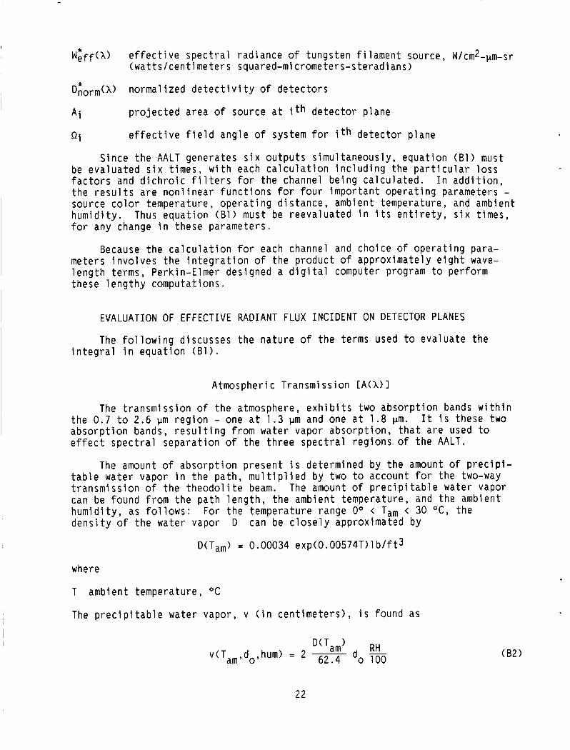
The amount o f a b s o r p t i o n p r e s e n t i s de termined by t h e amount o f p r e c i p i - t a b l e wa te r vapor i n t h e p a t h , m u l t i p l i e d by two t o account f o r t h e two-way t r a n s m i s s i o n o f t h e t h e o d o l i t e beam. The amount o f p r e c i p i t a b l e wa te r vapor can be found from t h e p a t h l e n g t h , t h e ambien t t empera tu re , and t h e ambient h u m i d i t y , as fol lows: For t h e tempera tu re range Oo < Tam < 30 O C , t h e d e n s i t y o f t h e wa te r vapor D can be c l o s e l y approx imated by
D(Tam) = 0.00034 exp(0 .00574T) l b / f t 3
where
T ambient t empera tu re , O C
The p r e c i p i t a b l e water vapor , v ( i n c e n t i m e t e r s ) , i s f ound as
D(Tam) RH d ,hum> = 2 ~ d - o 62.4 o 100 (B2)
22

where
' G lass p a t h Number o f Number of 1 ength , a i r - g l a s s g o l d
i n . surfaces r e f l e c t i o n s
Soda I n f r a s i l 1 ime I
0.50 4.20 21 10
do p a t h l e n g t h , cm
4.20
4.70 4.70
RH r e l a t i v e h u m i d i t y , p e r c e n t
11 1 1
For F l o r i d a use an RH o f 90 p e r c e n t , a Tam o f 90 O F (32 .2 OC), and d o ' s o f 450 and 833 were e l e c t e d .
D i c h r o i c F i l t e r T ransmiss ion [F;(X)I
To t a k e advantage o f t h e n a t u r a l s e p a r a t i o n o f t h e 0 .7 - t o 2.6-pm r e g i o n i n t o t h r e e separa te r e g i o n s because o f wa te r vapor a b s o r p t i o n , v a r i o u s d i c h r o i c f i l t e r s were des igned t o s p l i t t h e t h r e e r e g i o n s a p a r t by s e l e c t i v e r e f l e c t i o n of one or two r e g i o n s and by t r a n s m i s s i o n of t h e r e m a i n i n g r e g i o n s . Thus, com- b i n a t i o n s o f d i f f e r e n t f i l t e r s p e r m i t t h e i s o l a t i o n , a t t h e v a r i o u s d e t e c t o r p lanes , o f a s i n g l e s p e c t r a l r e g i o n .
Sys tern Component Transmi s s i o n L; (1) 1
The system component t r a n s m i s s i o n f a c t o r , e v a l u a t e d for each channe l , must t a k e i n t o account t h e f o l l o w i n g l o s s e s : ( 1 ) a t t e n u a t i o n i n g l a s s e lements , ( 2 ) l osses a t r e f l e c t i n g s u r f a c e s , ( 3 ) l o s s e s a t a i r - g l a s s s u r f a c e s , and ( 4 ) f i l a - ment r e i m a g i n g system l o s s e s
G lass t r a n s m i t t a n c e . - The r e l a t i v e t r a n s m i t t a n c e o f v a r i o u s o p t i c a l g lasses i s a f u n c t i o n o f wave length . O f t h e g lasses cons ide red (BK-7, Homosil, F l i n t , I n f r a s i l I, and soda l i m e ) , I n f r a s i l I was s e l e c t e d f o r a l l t r a n s m i t t i n g elements of the system because o f i t s s u p e r i o r l ong -wave leng th - t ransmiss ion c h a r a c t e r i s t i c s . The f o l l o w i n g t a b l e g i v e s t h e t o t a l g l a s s t h i c k n e s s e s t r a - ve rsed by t h e energy c o n t a i n e d i n t h e v a r i o u s channe ls as w e l l as o t h e r system component t r a n s m i s s i o n f a c t o r pa ramete rs .
Synchro e r r o r I n e r t i a l e r r o r Synchro a c q u i s i t i o n I n e r t i a l a c q u i s i t i o n Sway AGC
I I I
F i l a m e n t r e i m a g i n g
sys t e m t r a n s m i t t a n c e
0.5
1 1 .o 1 .o
R e f l e c t i n g Element R e f l e c t a n c e . - Avai l a b i 1 i t y o f h i g h - r e f l e c t i v i t y m e t a l l i c c o a t i n g s i s v e r y l i m i t e d ; o n l y t h r e e c o a t i n g s - aluminum, g o l d , and s i l v e r - appeared t o be f e a s i b l e . S i l v e r has t h e h i g h e s t r e f l e c t i v i t y over t h e
23
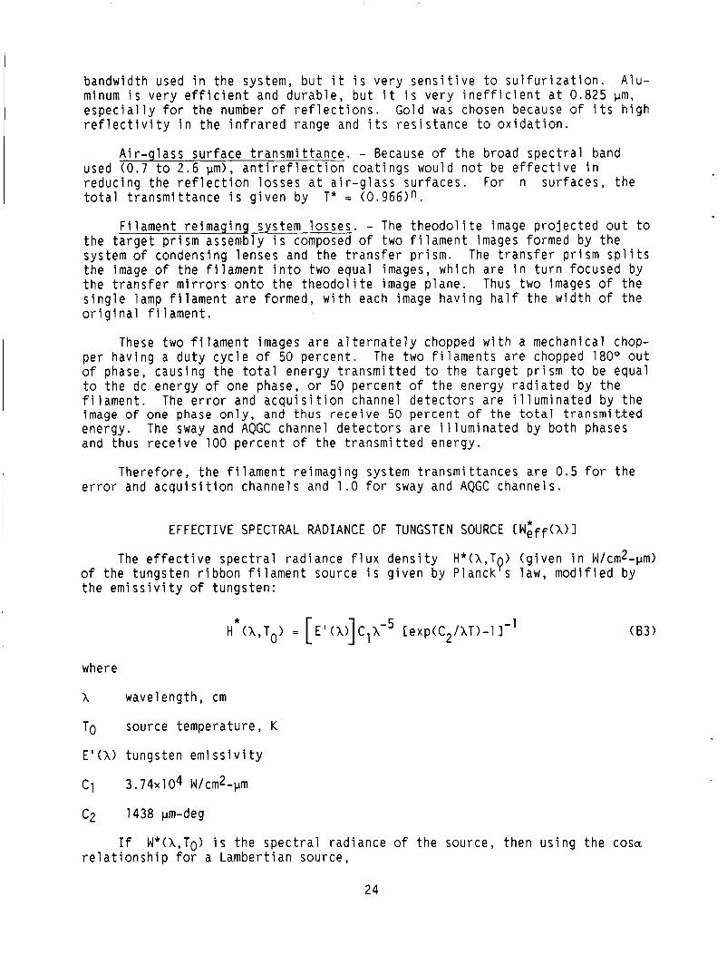
bandwidth used in the system, but it is very sensitive to sulfurization. Alu- minum is very efficient and durable, but it is very inefficient at 0.825 pm, especially for the number of reflections. Gold was chosen because of its high reflectivity in the infrared range and its resistance to oxidation.
Air-glass surface transmittance. - Because of the broad spectral band used (0.7 to 2.6 um), antireflection coatinqs would not be effective in reducing the reflection losses at air-glass-surfaces. For n surfaces, the total transmittance is given by T* = (0.966)n.
Filament reimaging system losses. - The theodolite image projected out to
The transfer prism splits the target prism assembly is composed of two filament images formed by the system of condensing lenses and the transfer prism. the image of the filament into two equal images, which are in turn focused by the transfer mirrors onto the theodolite image plane. Thus two images of the single lamp filament are formed, with each image having half the width of the original filament.
These two filament images are alternately chopped with a mechanical chop- per having a duty cycle of 50 percent. The two filaments are chopped 180" out of phase, causing the total energy transmitted to the target prism to be equal to the dc energy of one phase, or 50 percent of the energy radiated by the filament. The error and acquisition channel detectors are illuminated by the image o f one phase only, and thus receive 50 percent of the total transmitted energy. The sway and AQGC channel detectors are illuminated by both phases and thus receive 100 percent of the transmitted energy.
Therefore, the filament reimaging system transmittances are 0.5 for the error and acquisition channels and 1.0 for sway and AQGC channels.
EFFECTIVE SPECTRAL RADIANCE OF TUNGSTEN SOURCE [WEff(X) 1
The effective spectral radiance flux density H*(X,T ) (given in W/cmz-pm) 0 of the tungsten ribbon filament source is given by Planck s law, modified by the emissivity of tungsten:
where
x wavelength, cm
TO source temperature, K
E'(X> tungsten emissivity
C1 3.74~104 W/cm2-pm
C2 1438 pm-deg
relationship for a Lambertian source, If W*(X,To) is the spectral radiance of the source, then using the cosa
24
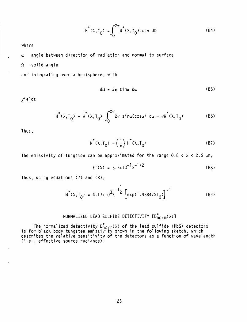
H dl (X,To) = ~ m W * ~ h , T o ) c ~ s o dQ
where
a ang le between d i r e c t i o n o f r a d i a t i o n and normal t o s u r f a c e
Q s o l i d ang le
and i n t e g r a t i n g o v e r a hemisphere, w i t h
dQ = 2rr s i n u da
y i e l d s
Thus,
(84)
(85)
(86)
(87)
The e m i s s i v i t y o f t u n g s t e n can be approx imated f o r t h e range 0.6 < X < 2 . 6 pm,
(88 ) 1 1 /2 E'th) = 3 . 5 ~ 1 0 - X-
Thus, u s i n g e q u a t i o n s ( 7 ) and ( 8 ) ,
-1 1 * W (X,TO) = 4 . 1 7 ~ 1 0 ~ ~ - ~ ' [ exp ( l .4384/XTO)] (89)
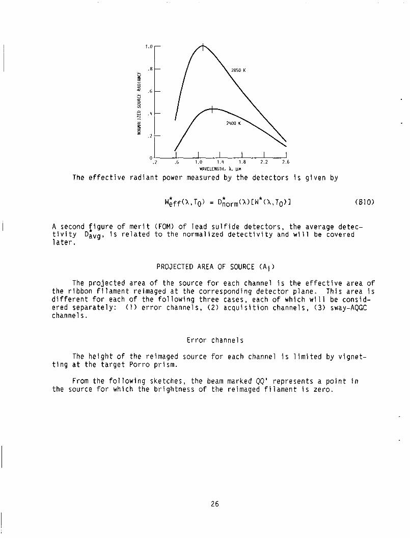
NORMALIZED LEAD SULFIDE D E T E C T I V I T Y CDiorm(X) 1
The n o r m a l i z e d d e t e c t i v i t y Drform(X) o f t h e l e a d s u l f i d e (PbS) d e t e c t o r s i s f o r b l a c k body t u n g s t e n e m i s s i v i t y shown i n t h e f o l l o w i n g ske tch , wh ich d e s c r i b e s t h e r e l a t i v e s e n s i t i v i t y o f t h e d e t e c t o r s as a f u n c t i o n o f wave length ( i . e . . e f f e c t i v e source r a d i a n c e ) .
25
1.0
.8 W U L
z n c+
W U cx T3 0 v)
.6
0 . 2 .6 1.0 1.11 1.8 2 . 2 2.6
WAVELENGTH. A. pM
The e f f e c t i v e r a d i a n t power measured by t h e d e t e c t o r s i s g i v e n by
A second f i g u r e o f m e r i t (FOM) of l e a d s u l f i d e d e t e c t o r s , t h e average detec- t i v i t y 1 a t e r .
Davg, i s r e l a t e d t o t h e n o r m a l i z e d d e t e c t i v i t y and w i l l be covered
PROJECTED AREA OF SOURCE ( A i )
The p r o j e c t e d a rea of t h e source f o r each channel i s t h e e f f e c t i v e a rea o f t h e r i b b o n f i l a m e n t reimaged a t t h e c o r r e s p o n d i n g d e t e c t o r p l a n e . Th is a rea i s d i f f e r e n t f o r each of t h e f o l l o w i n g t h r e e cases, each o f which w i l l be cons id - e red s e p a r a t e l y : ( 1 ) error channels , ( 2 ) a c q u i s i t i o n channe ls , (3) sway-AQGC channel s.
Error channels
The h e i g h t o f t h e reimaged source for each channel i s l i m i t e d by v i g n e t - t i n g a t t h e t a r g e t Porro p r i s m .
From t h e f o l l o w i n g sketches, t h e beam marked QQ' r e p r e s e n t s a p o i n t i n t h e source for which t h e b r i g h t n e s s o f t h e reimaged f i l a m e n t i s z e r o .
26

. do - APERTURE VIGNETTING IMAGE BRIGHTNESS
CHARACTERISTICS
REACT1 VE IMAGE BRIGHTNESS
Since the target Porro prism will return any beam having a deviation in eleva- tion back along the direction of incidence, any point closer to the axis will be reimaged with a brightness greater than zero. This limiting image height hQ is thus found as
where
HA' theodolite aperture height
Hpr prism height
f theodolite focal length
do operating di stance
The height hvig at which vignetting begins is given by
Thus, the effective height heff of the image shown above is equal t o
The width of the image projected onto the error detectors i s not limited by aperture vignetting but is determined by the angular deviation target Porro prism. At zero deviation, no energy reaches the error detectors through the sensing prism. (See the following sketch.)
p of the
27

MASKING 7
MASKING 7\
MASKING \
W
NULL CONDITION
-~
ERROR CONDITION L SENSING PRISM
When t h e t a r g e t Porro p r i s m i s r o t a t e d th rough an ang le r o t a t e d th rough an ang le 2p, caus ing a s t r i p of t h e image o f w i d t h w t o f a l l on t h e c l e a r nose o f t h e sens ing p r i s m .
p t h e image i s
Thus,
w = 2 p f (814)
Combining t h i s w i t h channels i s
hef f , t h e p r o j e c t e d a r e a o f t h e source f o r t h e e r r o r
where
p angu la r d e v i a t i o n of t a r g e t Porro p r i s m , r a d
A c q u i s i t i o n Channels
Since t h e same p r i sms a r e used f o r t h e e r r o r and a c q u i s i t i o n channe ls , t h e e f f e c t i v e h e i g h t o f t h e reimaged source f o r t h e a c q u i s i t i o n channe ls i s g i v e n by equa t ion (613).
However, t h e w i d t h , w , of t h e reimaged source i s de te rm ined by v i g n e t t i n g a t t h e t h e o d o l i t e a p e r t u r e fo r t h e case shown i n t h e f o l l o w i n g ske tches .
28
I "nose ,-PRISM
r PORRO ROOF PRISM
- -I--'-I
APERlURF V l t i N E l l l N G A l I H E O D O L I K NULL IMAti I 1IK lGHINtSS C I I A R A C I I R I S I ICs A I
I Ill 01101 I I t NLll I
RELAT I VE I MAGE BRItiHTNESS
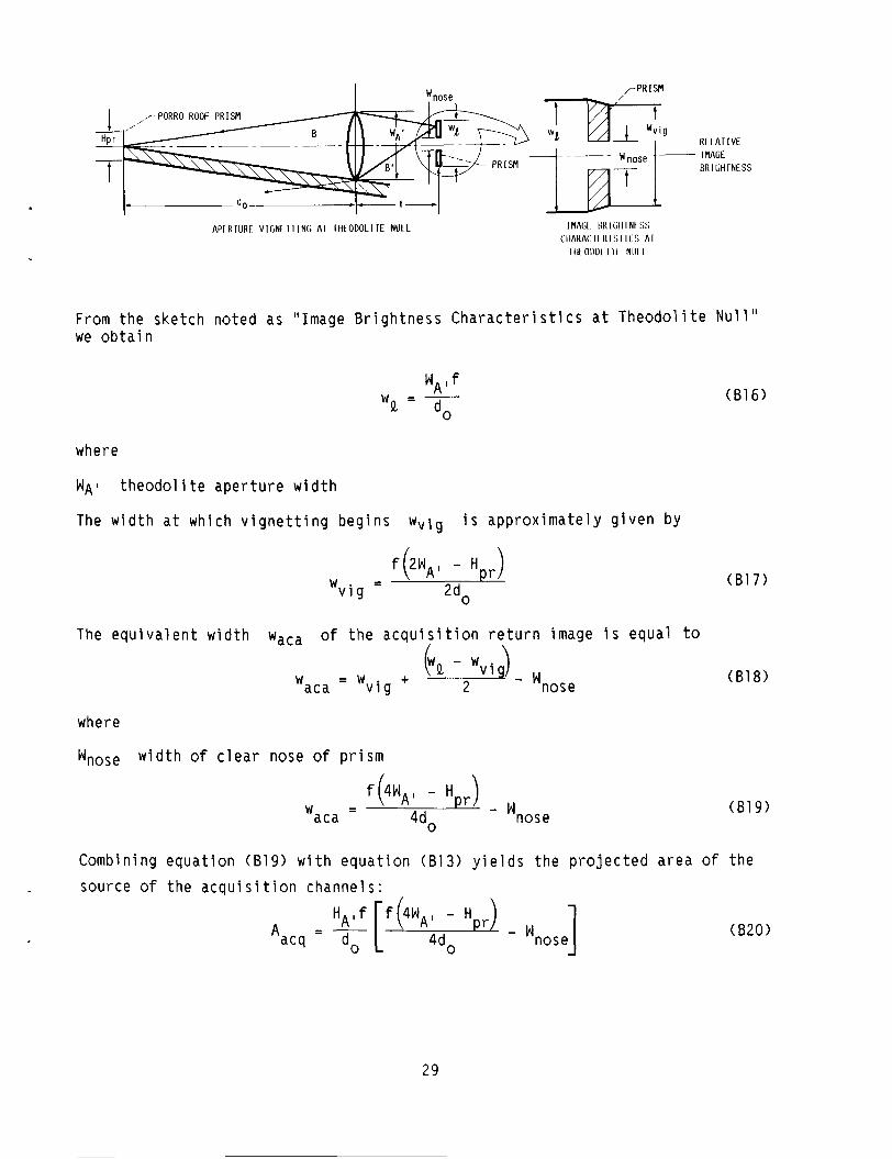
From t h e ske tch no ted as "Image B r i g h t n e s s C h a r a c t e r i s t i c s a t T h e o d o l i t e Nul 1 " we o b t a i n
where
W A I t h e o d o l i t e a p e r t u r e w i d t h
The w i d t h a t which v i g n e t t i n g b e g i n s Wvig i s a p p r o x i m a t e l y g i v e n by
- f (2wA l - H p r ) -
" v i g 2d0
The e q u i v a l e n t w i d t h Wacs o f t h e a c q u i s i t i o n r e t u r n image i s equa l t o / \
VQ - wv iqJ - 2 + -
aca - 'v ig W
where
'nose w i d t h o f c l e a r nose o f p r i s m
- 'nose f (4wA l - Hpr
- - 4do aca W
(B17)
(B18)
(B19)
Combining e q u a t i o n (B19) w i t h e q u a t i o n (813) y i e l d s t h e p r o j e c t e d a r e a of t h e source o f t h e a c a u i s i t i o n channe ls :
H A ' f [ f ( 4 w A 1 - Hpr) - ] 'nose A = -
acq do 4d0 (820)
29
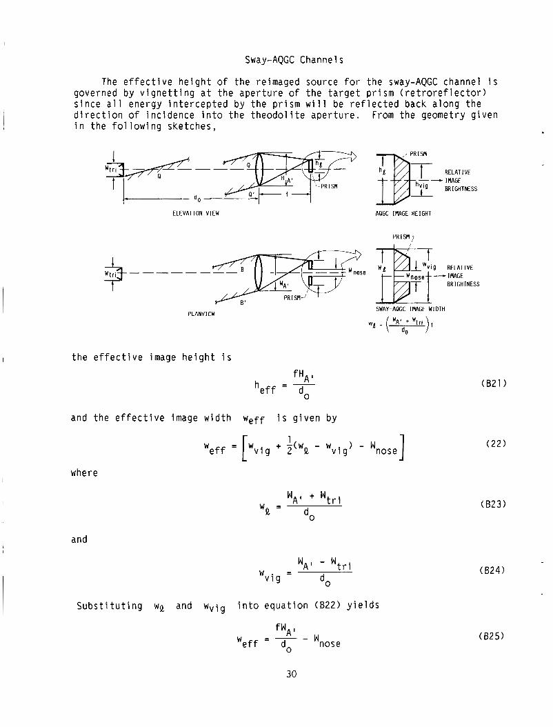
Sway-AQGC Channels
The e f f e c t i v e h e i g h t o f t h e reimaged source f o r t h e sway-AQGC channel i s governed by v i g n e t t i n g a t t h e a p e r t u r e o f t h e t a r g e t p r i s m ( r e t r o r e f l e c t o r ) s i n c e a l l energy i n t e r c e p t e d by t h e p r i s m w i l l be r e f l e c t e d back a l o n g t h e d i r e c t i o n o f i n c i d e n c e i n t o t h e t h e o d o l i t e a p e r t u r e . i n t h e f o l l o w i n g ske tches ,
From t h e geometry g i v e n
w u -
! / ELEVATION VIEW
PLANVIEW
t h e e f f e c t i v e image h e i g h t i s
fHA I - - h e f f - do
and t h e e f f e c t i v e image w i d t h Weff i s g i v e n by
where
and
RELATIVE -+ IMAGE
AQGC IMAGE HEIGHT
P R I S M ?
SWAY-AQGC IMAGE WIDTH
1 W e f f = [wv ig + - wv ig ) - wnose]
- 'AI + 'tri
do 'Q -
'AI - 'tri - - 'vi g
S u b s t i t u t i n g W Q and Wvig i n t o e q u a t i o n (822) y i e l d s
f w A l 'nose -
' e f f do
(621)
( 2 2 )
(623)
(624)
(825)
30

Thus the p r o j e c t e d a rea o f t h e source f o r t h e sway and AGC channels i s
Asway,AQGC = ( F)(f~~l ioWnose) (826)
E f f e c t i v e F i e l d Angle f o r i t h Detector
The s o l i d f i e l d ang le Q of t h e system for each channel i s determined by t h e a p e r t u r e areas o f t h e co r respond ing t a r g e t p r i s m . As shown i n t h e f o l l o w i n g ske tch , t h e a c t u a l p o s i t i o n of t h e t a r g e t p r i s m anywhere w i t h i n t h e r e g i o n o f c o l l i m a t e d beams i s e q u i v a l e n t t o a p o s i t i o n a t t h e t h e o d o l i t e a p e r t u r e .
EQUIVALENT POSIT ION OF PORRO ROOF PRISM-,
------ -4- I LACTUAL POSITION OF
PORRO ROOF PRISM
Thus, t h e s o l i d a n g l e p resen ted t o t h e source i s g i v e n by
A Ql = 9 ( i n s t e r a d i a n s )
f
where
(827)
A p r , i p r i s m a rea o f i t h p r i s m
SPECTRAL RADIANT FLUX D E N S I T Y AT DETECTOR PLANES
The measure o f r e l a t i v e energy a v a i l a b l e t o t h e channels o f t h e t h e o d o l i t e i s t h e s p e c t r a l r a d i a n t f l u x d e n s i t y d e t e c t o r p l a n e s . e q u a t i o n (81) w i t h r e s p e c t to Q as fol lows:
H i ( X ) ( g i v e n i n W/cm2-pm) a t t h e v a r i o u s T h i s q u a n t i t y i s f ound by i n t e g r a t i n g t h e i n t e g r a n d of
Error Channel Performance
(828)
Three F O M ' s a r e a p p l i c a b l e t o t h e performance o f t h e t h e o d o l i t e e r r o r channels : ( 1 ) a n g u l a r s e n s i t i v i t y ( g i v e n i n W/arc-sec), ( 2 ) s i g n a l - t o - n o i s e ( S / N > r a t i o p e r arc-sec, and (3) a n g u l a r r e s o l u t i o n .
31
Angu lar s e n s i t i v i t y . - Angu la r s e n s i t i v i t y of each e r r o r channel i s found by e v a l u a t i n g e q u a t i o n ( B l ) , u s i n g t h e p r o j e c t e d source d a t a from e q u a t i o n (815) c o r r e s p o n d i n g t o 1 a rc -sec d e v i a t i o n o f t h e t a r g e t p r i sm.
S igna l - to -no ise r a t i o p e r a rc -sec . - Be fo re f i n d i n g t h e s y s t e m S/! r a t i o p e r a rc -sec of e r r o r f o r t h e e r r o r channe ls , t h e average d e t e c t i v i t y Davg o f t h e PbS d e t e c t o r s must be used t o o b t a i n t h e d e t e c t o r S I N r a t i o .
D e t e c t i v i t y . - Average d e t e c t i v i t y D i v g o f PbS d e t e c t o r s i s spec i - f i e d for a s p e c i f i c o p t i c a l chopp ing f requency and a s p e c i f i c color tempera ture To, and has t h e u n i t s
c m f i (4 *
U s i n g Davg, t h e S I N r a t i o i s f ound as
* S I N = D a" g ( A s A f ) - l I 2 ( P )
where
( 8 2 9 )
A s sway d e t e c t o r a rea , cm2
A f ' system e l e c t r i c a l bandwid th , Hz
P r a d i a n t power, W
The d e t e c t i v i t y D:vg i s o b t a i n e d by measur ing t h e S I N r a t i o o b t a i n e d w i t h a b lackbody source a t a s p e c i f i e d color tempera ture . t h e r a d i a n t energy a c t u a l l y d e t e c t e d by t h e d e t e c t o r i s t h e i n t e g r a l * of t h e
( i / e . , Weff(X,T 1 =
D
tempera tu re .
S ince
b r i g h t n e s s of t h e source we igh ted by t h e no rma l i zed d e t e c t i v i t y Dnorm (1) * * * (X> [W ( X , T O ) I ) t h e average d e t e c t i v i t y Dnorm * 0
avg i s v a l i d o n l y when used w i t h a source h a v i n g t h e s p e c i f i e d color
* U s i n g t h e n o r m a l i z e d d e t e c t i v i t y Dmax, independent o f c o l o r t empera tu re , as
D;orm(X), one can o b t a i n a q u a n t i t y
(830)
where
Wgt 1, TO)
TO source color tempera ture for D i v g ( T o )
b l ack body b r i g h t ne s s
3 2
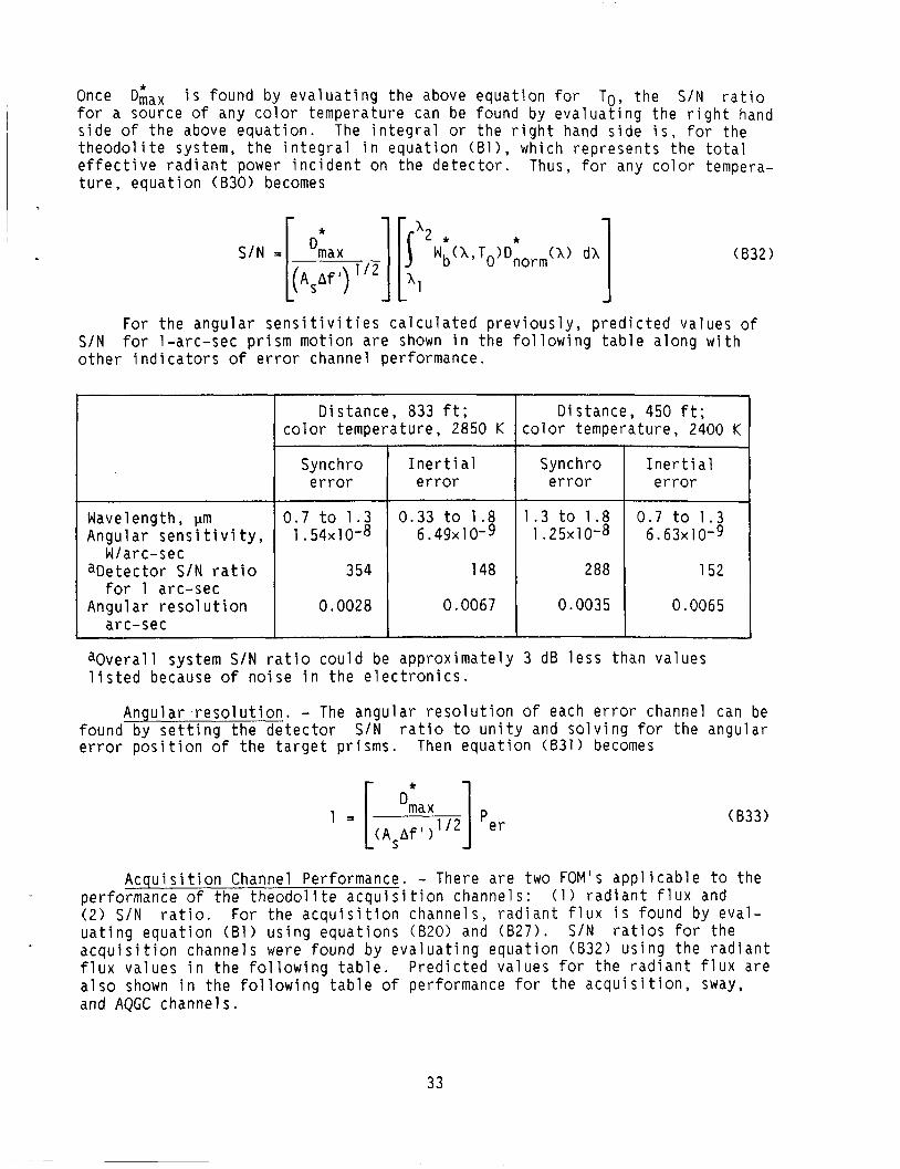
* Once Dmax i s found by e v a l u a t i n g t h e above e q u a t i o n fo r To, t h e S / N r a t i o f o r a source o f any c o l o r t empera tu re can be found by e v a l u a t i n g t h e r i g h t hand s i d e o f t h e above e q u a t i o n . The i n t e g r a l or t h e r i g h t hand s i d e i s , fo r the t h e o d o l i t e system, t h e i n t e g r a l i n e q u a t i o n ( B l ) , which r e p r e s e n t s the t o t a l e f f e c t i v e r a d i a n t power i n c i d e n t on t h e d e t e c t o r . Thus, f o r any color tempera- t u r e , e q u a t i o n (830) becomes
D i s t a n c e , 833 ft; c o l o r t empera tu re , 2850 K
S / N =
D is tance , 450 ft; c o l o r tempera ture , 2400 K
[( A s A f Olfiax I) v2]
0.33 to 1 .8 6 . 4 9 ~ 1 0 - 9
148
0.0067
(832 1
1 .3 t o 1 .8 0.7 t o 1.3 1 . 2 5 ~ 1 0 - 8 6 . 6 3 ~ 1 0 - 9
288 152
0.0035 0.0065
For t h e a n g u l a r s e n s i t i v i t i e s c a l c u l a t e d p r e v i o u s l y , p r e d i c t e d va lues of S / N f o r 1-arc-sec p r i s m m o t i o n a r e shown i n t h e f o l l o w i n g t a b l e a l o n g w i t h o t h e r i n d i c a t o r s o f e r r o r channel per fo rmance.
Wavelength, pm Angu la r sens i t i v i t y ,
W / a r c- s e c a D e t e c t o r S / N r a t i o
for 1 arc-sec Angu la r r e s o l u t i o n
arc -sec
Synchro e r r o r
0 . 7 t o 1 . 3 1 .54x10-8
354
0.0028
~-
I n e r t i a1 Synchro I n e r t i a1 e r r o r I e r r o r 1 e r r o r
a O v e r a l l system S / N r a t i o c o u l d be a p p r o x i m a t e l y 3 d8 l e s s than va lues l i s t e d because o f n o i s e i n t h e e l e c t r o n i c s .
Angu la r r e s o l u t i o n . - The a n g u l a r r e s o l u t i o n o f each e r r o r channel can be found by s e t t i n g t h e d e t e c t o r S / N r a t i o t o u n i t y and s o l v i n g for t h e angu la r e r r o r p o s i t i o n o f t h e t a r g e t prisms. Then e q u a t i o n (831) becomes
(833)
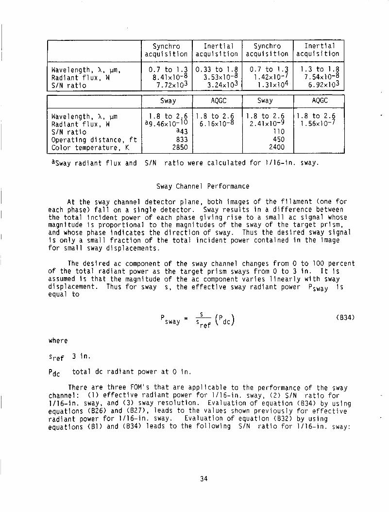
A c q u i s i t i o n Channel Performance. - There a r e two F O M ' s a p p l i c a b l e t o t h e per fo rmance of t h e t h e o d o l i t e a c q u i s i t i o n channe ls : ( 2 ) S / N r a t i o . For t h e a c q u i s i t i o n channe ls , r a d i a n t f l u x i s found by e v a l - u a t i n g e q u a t i o n (81) u s i n g e q u a t i o n s (820) and (827 ) . a c q u i s i t i o n channe ls were found by e v a l u a t i n g e q u a t i o n (832) u s i n g t h e r a d i a n t f l u x va lues i n t h e f o l l o w i n g t a b l e . P r e d i c t e d va lues for t h e r a d i a n t f l u x a re a l s o shown i n t h e f o l l o w i n g t a b l e o f performance fo r t h e a c q u i s i t i o n , sway, and AQGC channe ls .
( 1 ) r a d i a n t f l u x and
S / N r a t i o s for the
33
I
Synchro I n e r t i a l Synchro I n e r t i a1 a c q u i s i t i o n a c q u i s i t i o n a c q u i s i t i o n a c q u i s i t i o n
Wavelength, 1, pm, 0.7 t o 1.3 0 .33 t o 1 .8 0 .7 t o 1 .3 1.3 t o 1.8 Rad ian t f 1 ux , W 8 . 4 1 ~ 1 0 - 8 3 . 5 3 ~ 1 0 - 8 1 . 4 2 ~ 1 0 - 7 7 . 5 4 ~ 1 0 - 8 S / N ra t io 7 . 7 2 ~ 1 03 3 . 2 4 ~ 1 0 3 1 . 3 1 ~ 1 0 4 6 . 9 2 ~ 1 0 3
Sway Channel Performance
Sway
Wavelength, X , pin 1.8 t o 2.6 Rad ian t f l u x , W a 9 . 4 6 ~ 1 0 - 1 0 SIN r a t i o a43 O p e r a t i n g d i s t a n c e , f t 833 Color tempera tu re , K 2850
A t t h e sway channel d e t e c t o r p l a n e , b o t h images o f t h e f i l a m e n t (one f o r each phase) f a l l on a s i n g l e d e t e c t o r . Sway r e s u l t s i n a d i f f e r e n c e between t h e t o t a l i n c i d e n t power o f each phase g i v i n g r i s e t o a sma l l ac s i g n a l whose magnitude i s p r o p o r t i o n a l t o t h e magnitudes o f t h e sway of t h e t a r g e t p r i s m , and whose phase i n d i c a t e s t h e d i r e c t i o n o f sway. Thus t h e d e s i r e d sway s i g n a l i s o n l y a smal l f r a c t i o n o f t h e t o t a l i n c i d e n t power c o n t a i n e d i n t h e image for smal l sway d i sp lacemen ts .
AQGC Sway AQGC
1 .8 t o 2 . 6 1.8 t o 2 .6 1.8 t o 2.6 6 . 1 6 ~ 1 0 - 8 2 . 4 1 ~ 1 0 - 9 1 . 5 6 ~ 1 0 - 7
110 450
2400
I The d e s i r e d ac component o f t h e sway channel changes from 0 t o 100 p e r c e n t of t h e t o t a l r a d i a n t power as t h e t a r g e t p r i s m sways from 0 t o 3 i n . I t i s assumed i s tha . t t h e magnitude o f t h e ac component v a r i e s l i n e a r l y w i t h sway d i sp lacemen t . Thus f o r sway s , t h e e f f e c t i v e sway r a d i a n t power Psway i s equal t o
S - 'sway - Sref ('dc) (B34)
where
pdc
There a r e t h r e e FOM's t h a t a r e a p p l i c a b l e t o t h e per fo rmance o f t h e sway channe l : ( 1 ) e f f e c t i v e r a d i a n t power for 1 /16 - in . sway, ( 2 ) S / N r a t i o f o r 1 /16 - in . sway, and ( 3 ) sway r e s o l u t i o n . E v a l u a t i o n o f e q u a t i o n (834) by u s i n g e q u a t i o n s (626) and (827) , leads t o t h e va lues shown p r e v i o u s l y f o r e f f e c t i v e r a d i a n t power f o r 1 /16 - in . sway. e q u a t i o n s (61) and (834) l eads t o t h e f o l l o w i n g S / N r a t i o f o r 1 / 1 6 - i n . sway:
t o t a l dc r a d i a n t power a t 0 i n .
E v a l u a t i o n o f e q u a t i o n (832) by u s i n g
34

where
( 8 3 5 )
AS sway detector area
Psway S sway, in.
radiant power from equation ( 8 3 4 )
Sref sway of 3 in.
Sway resolution is found by evaluating equation ( 8 3 5 ) for an S I N ratio of unity and solving for s . See table of error channel performance on p. 33 for the cases noted.
Acquisition Gain Control Channel Performance
The only meaningful FOM applicable to the performance of the acquisition gain control (AQGC) channel is the total radiant flux, which is found as follows: total radiant flux is taken as the sum of energy contained in both phases of the reimaged filament. In the AQGC detector, there is a central dead zone that vignettes the image such that only 73 percent of the energy is detected. Using equation (87 ) yields an effective radiant power:
PAQGC = 0.73Pi where
P i radiant flux found from equation (81).
Note: Predicted angular resolutions of the two error channels, as well as the predicted sway resolution are two orders of magnitude below the values observed when the autocollimator is in actual use. The discrepancy is due to the degrading effect of atmospheric turbulence, which prevents the autocollimator from approaching the theoretical performance limits predicted.
Light Sources
During the design study phase, a review of all available light sources was made. Although particular emphasis was placed on the evaluation of new devel- opments, such as gas lasers and solid-state emitters, a tungsten filament lamp was selected as the source.
Evaluation of each source was based on the following criteria:
(1) Spectral characteristics (brightness) ( 2 ) Uniformity of brightness over the effective source area (3) Lifetime (4) Stabi 1 i ty ( 5 ) Complexity of the associated electronics
35
\

The f o l l o w i n g t a b l e summarizes t h e l i g h t source c h a r a c t e r i s t i c s :
B r i htness i n 0.9- t o 2 . 6 m band a-50 a-25 b55 -23 -125 -10-3 >50
Spectra 1
Number o f sources needed
Continuous
Excel len t
Continuous Continuous Emission Narrow Narrow band Continuous 1 ines band a t 0.9pm with l ines
Good Good Good Insu f f i c i en t I n s u f f i c i e n t Poor area area
Stabi 1 i t y
Lifet ime, hr
Good Good Excel len t Good Poor Poor Poor
>10 000 >10 000 <loo0 10 t o 100 <10 000 <10
R e s u l t s o f t h e sources cons ide red a r e summarized i n t h e f o l l o w i n g t a b l e :
Very very Modest High Modest High sinple sinp e
Carplexity o f very associated simp e electronics
i '-
D e t e c t o r Wavelength o f peaka,
Pm
G a l l i u m a r s e n i d e S i 1 i c o n German i um Lead s u l f i d e Lead s e l e n i d e I n d i u m a r s e n i d e I n d i u m an t imon ide
Long wave length Response t ime , c u t o f f , t ,
h u t , psec Pm
1013 2x10¹² 2x10¹⁰
1011 3x1 08 3x 10⁹ 5x1 O7
0.85 . 9
1.6 2 . 4 3.5 3 .4 6.6
0 .95 1 . 1 1 .8 2 .8 4.3 3.7 7 .4
>400: > 500 < l o o < 300 < 4 < 1 <.2
aThe wave length depends on t h e mode of o p e r a t i o n : pho toconduc t i ve mode o f o p e r a t i o n .
i t i s much s h o r t e r for t h e
S p e c t r a l c h a r a c t e r i s t i c s . - A t u n g s t e n lamp i s e s s e n t i a l l y a b lackbody
Tungsten lamps a r e o p e r a t e d i n t h e 2500- t o 3000-K c o l o r - t e m p e r a t u r e whose b r i g h t n e s s i s g i v e n by P l a n c k ' s law m o d i f i e d by t h e e m i s s i v i t y o f tung- s t e n . r e g i o n where a p p r o x i m a t e l y 80 p e r c e n t of a l l r a d i a n t energy f a l l s w i t h i n t h e 0.7- t o 2.6-pm band as shown i n t h e f o l l o w i n g t a b l e :
36
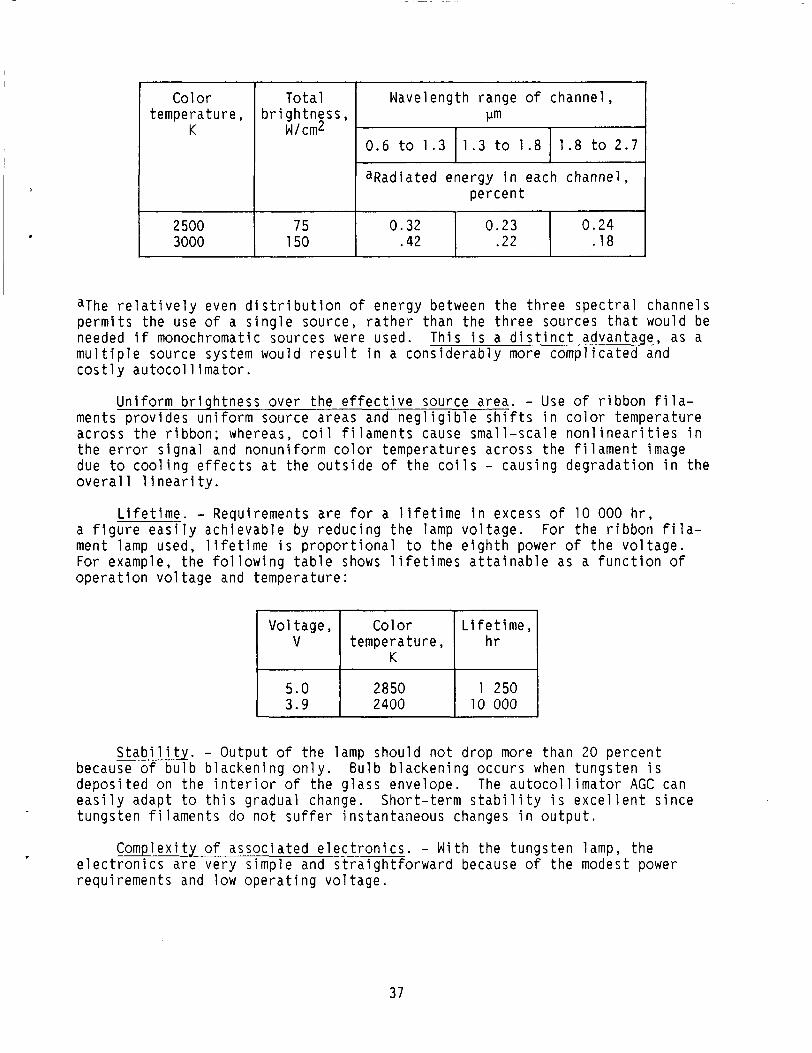
Color tempera ture ,
K 0.6 t o 1.3 1.3 t o 1 .8
2 500 3000
1 .8 t o 2.7
T o t a l b r i g h t n e s s ,
W/cm2
0.32 0 .23 .42 .22
75 150
0 .24 .18
Vol tage , V
&The r e l a t i v e l y even d i s t r i b u t i o n o f energy between t h e t h r e e s p e c t r a l channels p e r m i t s t h e use o f a s i n g l e source , r a t h e r than t h e t h r e e sources t h a t would be needed i f monochromatic sources were used. T h i s i s a d i s t i n c t advantage, as a m u l t i p l e source system would r e s u l t i n a c o n s i d e r a b l y more c o m p l i c a t e d and c o s t l y a u t o c o l l i m a t o r .
Color
K
L i f e t i me, tempera tu re , h r
U n i f o r m b r i g h t n e s s o v e r t h e e f f e c t i v e source a rea . - Use o f r i b b o n f i l a - ments p r o v i d e s u n i f o r m source areas and n e g l i g i b l e s h i f t s i n c o l o r t empera tu re ac ross t h e r i b b o n ; whereas, c o i l f i l a m e n t s cause s m a l l - s c a l e n o n l i n e a r i t i e s i n t h e e r r o r s i g n a l and n o n u n i f o r m color tempera tures ac ross t h e f i l a m e n t image due t o c o o l i n g e f f e c t s a t t h e o u t s i d e o f t h e c o i l s - caus ing d e g r a d a t i o n i n t h e o v e r a l l l i n e a r i t y .
5 .0 3.9
L i f e t i m e . - Requirements a r e f o r a l i f e t i m e i n excess o f 10 000 h r , a f i g u r e e a s i l y a c h i e v a b l e by r e d u c i n g t h e lamp v o l t a g e . fo r t h e r i b b o n f i l a - ment lamp used, l i f e t i m e i s p r o p o r t i o n a l t o t h e e i g h t h power o f t h e v o l t a g e . For example, t h e f o l l o w i n g t a b l e shows l i f e t i m e s a t t a i n a b l e as a f u n c t i o n o f o p e r a t i o n v o l t a g e and tempera tu re :
2850 1 250 2400 10 000
S t a b i l i t y . - Ou tpu t o f t h e lamp shou ld n o t d rop more than 20 p e r c e n t because o f b u l b b l a c k e n i n g o n l y . Bu lb b l a c k e n i n g o c c u r s when t u n g s t e n i s d e p o s i t e d on t h e i n t e r i o r o f t h e g l a s s enve lope. The a u t o c o l l i m a t o r AGC can e a s i l y adapt t o t h i s g radua l change. Shor t - te rm s t a b i l i t y i s e x c e l l e n t s i n c e t u n g s t e n f i l a m e n t s do n o t s u f f e r i ns tan taneous changes i n o u t p u t .
Comp lex i t y of a s s o c i a t e d e l e c t r o n i c s . - Wi th t h e t u n g s t e n lamp, t h e e l e c t r o n i c s a r e v e r y s imp le and s t r a i g h t f o r w a r d because o f t h e modest power requ i remen ts and low o p e r a t i n g v o l t a g e .
37

Sources Cons idered
Halogen c y c l e ( q u a r t z - l i n e ) t u n g s t e n lamp. - Th is lamp was cons ide red because o f i t s broad s p e c t r a l bandwidth and h i g h - o u t p u t t u n g s t e n c h a r a c t e r - i s t i c s , coupled w i t h i t s un ique q u a r t z - l i n e c h a r a c t e r i s t i c o f no b u l b b l a c k e n i n g ( b u l b b l a c k e n i n g i s avo ided by f i l l i n g t h e b u l b envelope w i t h a ha logen gas ) . However, s e v e r a l d isadvantages do e x i s t - c o i l f i l a m e n t , l i m i t e d l i f e t i m e , n e c e s s i t y f o r a comb ina t ion lamp mount and hea t s i n k , and minimum o p e r a t i n g c o l o r t empera tu re .
Glow d ischarge lamp. - Glow d i s c h a r g e lamps (neon, g low tube, e t c . ) have two fundamental d isadvantages - low o u t p u t and a s p e c t r a l o u t p u t composed o f emiss ion l i n e s d i s t r i b u t e d o v e r a smal l p o r t i o n o f t h e 0.7- to 2.0-pm s p e c t r a l o p e r a t i n g range. One would need t h r e e g low lamps t o s a t i s f y t h e r e q u i r e m e n t s .
Arc lamps. - These lamps s u f f e r from severa l s e r i o u s d isadvantages - poor s t a b i l i t y , smal l non-un i fo rm source area, v e r y s h o r t l i f e t i m e s , and v e r y h i g h power demand.
Gas l a s e r . - T f a m i l i a r c h a r a c t e r i monochromatic p lane
'he con t inuous wave (CW) gas l a s e r has t h r e e a t t r a c t i v e and s t i c s - v e r y h i g h b r i g h t n e s s and d i r e c t i o n a l i t y and h i g h l y - p o l a r i z e d o u t p u t . O f t hese , t h e f irst two c h a r a c t e r i s t i c s
l e n d themselves t o t h e o d o l i t e a p p l i c a t i o n , e s p e c i a l l y f o r long-range o p e r a t i o n and f o r a p p l i c a t i o n s where h i g h power i s needed t o p e n e t r a t e f o g o r c l o u d s . Gas l a s e r s a r e a v a i l a b l e i n a wide range o f wavelengths and i n a range o f o u t p u t power ( 1 mW to 100 W ) .
The t h i r d c h a r a c t e r i s t i c , m o n o c h r o m a t i c i t y , would d i c t a t e t h e use o f t h r e e l a s e r s as t h e source i n t h e p r e s e n t t h e o d o l i t e des ign . T h i s i s h ighTy u n d e s i r a b l e , s i n c e i t would s u b s t a n t i a l l y i n c r e a s e t h e c o m p l e x i t y o f t h e o p t i c s , as w e l l as t h e e l e c t r o n i c s .
Another p rob lem i n v o l v e d i n t h e use o f l a s e r s i n t h e p r e s e n t d e s i g n a r i s e s from t h e smal l e f f e c t i v e source a rea o f t h e l a s e r . I f t h e beam were focused i n t o an f / 4 beam (necessa ry t o f i l l t h e a u t o c o l l i m a t o r a p e r t u r e ) , the e f f e c t i v e source a rea would be a d i f f r a c t i o n - l i m i t e d s p o t s i z e s e v e r a l o r d e r s o f magnitude s m a l l e r t han t h e r e q u i r e d source area. To c o r r e c t t h i s problem, t h e source o p t i c s would have t o de-focus t h e beam i n some way or use f i b e r o p t i c s to f i l l t h e r e q u i r e d source a r e a w h i l e m a i n t a i n i n g t h e f / 4 a n g l e . Such de - focus ing o r sc ramb l ing would e f f e c t i v e l y reduce t h e o r i g i n a l l a s e r b r i g h t - ness and, t hus , reduce or e l i m i n a t e i t s p r i m a r y advantage o v e r a t u n g s t e n source.
A l though t h e l a s e r has g r e a t p o t e n t i a l f o r a u t o c o l l i m a t e d sys tems i n genera l ( p a r t i c u l a r l y s t a r - t r a c k e r s y s t e m s n o t r e q u i r i n g a f i n i t e source- r a d i a t i n g a r e a ) , t h e i r a p p l i c a t i o n t o t h e p r e s e n t c l a s s o f i n s t r u m e n t s does n o t appear f e a s i b l e a t t h i s t i m e .
S o l i d s t a t e d iodes . - These dev i ces s u f f e r from a number o f d isadvantages f o r o u r a p p l i c a t i o n , i n c l u d i n g ( 1 ) low o u t p u t , (2) narrow s p e c t r a l bandwidth - on t h e o r d e r o f 0 .1 pm, ( 3 ) sma l l source a rea , and ( 4 ) poor s t a b i l i t y .
Whi le t h e r e may be f u t u r e developments o f s t a b l e , h i g h - o u t p u t d iodes t h a t have e m i t t i n g areas l a r g e enough t o use i n t h e p r e s e n t d e s i g n , t h e na r row
spectral bandwidth of high-output diodes would still require the use of three separate sources. Thus, the diode is eliminated as an autocollimator source.
MODULATION
The method of source modulation is dependent to a large extent on the type of source being utilized. Since a ribbon strip tungsten filament was selected as the source, our attention is restricted to means of modulating this type of source.
Direct electrical modulation, either by using pulses or half-wave recti- fied sine waves, is practicable only at very low frequencies. The thermal inertia of the large filament precludes direct modulation of the source at frequencies above 30 Hz. small, on the order of 3 to 5 percent. It is possible to operate a system at 30 Hz, but the signal-to-noise ratio would be very poor because of the low percentage modulation.
At 30 Hz, the percentage modulation would be very
In addition, detector and transistor noise increase significantly at low frequencies as both devices are operating in the l/f noise region. The size of electrical components required, such as inductors and capacitors, increase significantly at this low frequency. An amplifier required to pass 30 Hz with- out significant phase distortion would require a low-frequency cutoff of less than 2 Hz.
The primary advantage of direct modulation is the absence of moving mechanical parts. Since this is an important consideration in establishing the reliability of the instrument, other static modulators were investigated. Among those are Kerr, Pockels, and Faraday cells. These static optical modu- lators have a number of advantages such as (1) no moving parts, ( 2 ) low power consumption, and (3) operation over a wide frequency range.
Kerr and Pockels cells are electro-optical devices which utilize an elec- trostatic field. This field is applied to certain materials to produce changes in the optical properties which cause an intensity modulation of the source.
In the Pockels cells, electric fields are applied to certain crystals such as ammonium dihydrogen phosphate (ADP) or potassium dihydrogen phosphate (KDP). These crystals, on application of the field, change from uniaxial to biaxial. Amplitude modulation is accomplished by passing a linearly polarized light beam through the modulator and then through another crossed polarizer. The applica- tion of a voltage will change the linearly polarized light to elliptically polarized light. The amplitude of the light passing through the crossed polar- izer will be a function of its ellipticity and, therefore, of the voltage on the crystal. Kerr cells function in much the same manner except that the mate- rial used is a liquid (nitrobenzene) instead of a crystal.
However, these modulators suffer from a number of serious disadvantages, particularly the low long-wavelength-transmission cutoff Xcut, which is 1.8 pm. Nitrobenzene and bromobenzene do exhibit increases in transmission, but they are beyond 3.0 pm. Thus, these devices cannot be used - especially for the sway-AQGC channel (1.8 to 2.8 pm). Other disadvantages of these modu- lators are that (1) high voltages are required for effective modulation (2000
39
to 20 000 V ) , and that the ( 2 ) light is polarized - the dichroic filters used for spectral separation react differently to polarized light. Changes in the light angle of incidence cause the cutoff points of the filters to shift drastically.
The Faraday cell also utilizes the rotation of a polarized light beam to cause extinction of the source, but with one difference. The Faraday cell utilizes a magneto-optical effect where the magnetic field causes the change in the optical properties of the material - usually bromobenzene. This cell has the same advantages and disadvantages mentioned before, except that high volt- age is not required but high currents are required to provide a sufficiently intense magnetic field.
Consideration was also given to the use of a "tuning fork light chopper," (eg., American Time Division). However, the main disadvantage of the tuning fork modulator is the limited amplitude of its blade. The maximum displacement of the chopper blade is 0.080 in., hence chopping must be done when the light beam width is small (i.e., near the focal point of the system) resulting in degradation of the signal shapes.
Consideration was now given to a motor-driven chopper. The disadvantage o f a well-balanced motor is its limited bearing life. However, since the motor in a chopper application essentially experiences no axial and very small radial forces, bearing life is greatly extended.
The main advantage of the motor-driven chopper is the great flexibility in positioning the chopper blades in the optical system. The synchronous motor provides a high-reliability device with flexibility in the design and, there- fore, was maintained for our design.
DETECTORS
Infrared detectors can be classified by their mechanism of detection. There are two broad classes of detectors ( 1 ) thermal, or phonon detectors, and ( 2 ) photon detectors.
Thermal detectors uti 1 ize some temperature-dependent property, such as resistivity of thermoelectric effect, to produce an electrical output when exposed to radiation. them, but their primary disadvantage - a long time constant - precludes their use in our design, (time constants vary from 30 msec to several seconds). chopping frequency we are to employ requires detectors with time constants no greater than 300 psec.
devices, depend on the interaction of incident photons which are absorbed in the material to produce excess charge carriers. the rate at which the photons are absorbed, hence, their spectral response is dependent on the energy of the photons. This means that the detector sensi- tivity is a function of the wavelength of the radiation. Photon devices have two advantages over thermal detectors, their response time i s much shorter (on the order of 1 psec to 1 msec), and, since their spectral response is limited, their response to background noise i s less.
These detectors have a number of advantages to recommend
The
Photon detectors, which include both photoemissive and solid-state
These detectors respond t o
40

I n pho toemiss i ve d e v i c e s , such as photod iodes and p h o t o m u l t i p l i e r s , e l e c - t r o n s a r e p h y s i c a l l y e j e c t e d from t h e p h o t o s e n s i t i v e surface and a c c e l e r a t e d by an e l e c t r o s t a t i c f i e l d . P h o t o m u l t i p l i e r tubes p r o v i d e h i g h s e n s i t i v i t y , f requency response up t o t h e megahertz range, and low n o i s e , b u t t h e i r p r i m a r y d isadvantage i s t h e i r l i m i t e d s p e c t r a l s e n s i t i v i t y . I n o u r r e g i o n o f i n t e r e s t , 0.7 to 1.35 pm, t h e quantum e f f i c i e n c y i s v e r y low, below 0.5 p e r c e n t . The i n h e r e n t g a i n o f t h e p h o t o m u l t i p l i e r i s t hus negated by t h e low e f f i c i e n c y of t h e photocathode. Because o f t h e i r low quantum e f f i c i e n c y and t h e i r need for h i g h - v o l t a g e s u p p l i e s , pho toemiss i ve dev i ces a r e n o t cons ide red fo r o u r des ign .
The r e m a i n i n g c l a s s o f pho ton d e t e c t o r s , s o l i d - s t a t e d e v i c e s , i n c l u d e s m a t e r i a l s such as g a l l i u m a r s e n i d e and selenium. i n t h e p h o t o c o n d u c t i v e mode or p h o t o v o l t a i c mode. con pho tod iodes , can be o p e r a t e d i n e i t h e r mode. Other m a t e r i a l s , such as l e a d s u l f i d e (PbS,) can be o p e r a t e d o n l y i n t h e pho toconduc t i ve mode.
These d e t e c t o r s may o p e r a t e Some dev ices , such as s i l i -
From t h e :able on p . 36, t h e f a c t o r s of p r i m a r y impor tance a r e ( 1 ) t h e d e t e c t i v i t y Davg or FOM f o r t h e d e t e c t o r and ( 2 ) t h e long-wave length c u t o f f Xcu t .
D e t e c t i v i t y i s a measure of t h e S I N r a t i o o f t h e d e t e c t o r
* l / n o i s e e q u i v a l e n t power avg 1 /2 D =
C ( a r e a ) (bandwi d t h ) 1
(Average d e t e c t i v i t y i s expressed i n cm-Hz1/2/W). S ince d e t e c t i v i t y i s wave- l e n g t h dependent, t h e S / N r a t i o i s a f u n c t i o n of t h e source tempera tu re . I t i s a l s o a f u n c t i o n o f t h e chopp ing f requency : above t h e upper l i m i t de te rm ined by t h e t i m e c o n s t a n t z and f o r f r e q u e n c i e s be low a p p r o x i m a t e l y 300 Hz - t h e r e g i o n o f l / f n o i s e . Over t h e f requency range de te rm ined by these upper and lower l i m i t s , Davg The d e t e c t i v i t y i s a l s o a f u n c t i o n of t empera tu re : i t inc reases as tempera ture decreases .
i t decreases for f requenc ies
i s independent o f f requency .
The t a b l e on p . 36 shows t h a t f o r t h e wave length of i n t e r e s t ( 0 . 7 * t o DaVg 3.0 pm) l e a d s u l f i d e (PbS) i s most s u p e r i o r because i t has a h i g h e r a t
a l l wavelengths o f i n t e r e s t .
The use o f d i f f e r e n t d e t e c t o r s f o r each channel - s i l i c o n i n t h e synchro p r i s m , PbS i n t h e r e m a i n i n g channe ls - was cons ide red b u t dropped because d i f f e r e n t p r e a m p l i f i e r s would have t o be s u p p l i e d fo r each t y p e * o f d e t e c t o r . The o n l y j u s t i f i c a t i o n f o r t h e use of s i l i c o n was i t s h i g h e r Davz, b u t s i n c e a v e r y good dec ided to m a i n t a i n t h e PbS d e t e c t o r s i n a l l o f t h e channe ls .
S / N r a t i o can be o b t a i n e d w i t h PbS i n t h e synchro c anne l , i t was
AUTOMATIC G A I N CONTROL
Exper ience ga ined w i t h t h e S a t u r n AALT, p o i n t e d o u t t h e d e s i r a b i l i t y o f an a u t o m a t i c g a i n c o n t r o l ( A G O system ( ! . e . , v a r i a t i o n s i n a tmospher i c t ransmis - s i o n , lamp v o l t a g e f l u c t u a t i o n s , and lamp a g i n g a r e t h e p r i m a r y f a c t o r s i n p r o d u c i n g s c a l e f a c t o r v a r i a t i o n s ) . changes and m a i n t a i n a c o n s t a n t s c a l e f a c t o r .
An AGC system can compensate f o r these
41

An AGC system has two i m p o r t a n t system parameters t h a t de te rm ine t h e method o f o p e r a t i o n . t i o n s and t h e o t h e r concerns t h e c o n t r o l method f o r v a r y i n g t h e g a i n .
One concerns t h e means o f sens ing t h e i n t e n s i t y v a r i a -
Sensing Element
The first problem i s p r i m a r i l y a f u n c t i o n o f t h e t ype o f o p t i c a l r e t u r n element t o be used. The i d e a l o p t i c a l d e v i c e would be an e lement whose r e t u r n beam would be i n s e n s i t i v e t o e i t h e r a n g u l a r or t r a n s l a t o r y m o t i o n . O f t h e p o s s i b l e dev i ces , P o r r o p r i sms a r e r e l a t i v e l y i n s e n s i t i v e t o p i t c h mo t ions about t h e i r apex b u t a r e s e n s i t i v e t o a n g u l a r mo t ions about t h e a x i s perpen- d i c u l a r t o the apex. Plane m i r r o r s would be even more u n s u i t a b l e because t h e y a r e s e n s i t i v e to p i t c h as w e l l as r o l l mo t ions . The d e v i c e t h a t b e s t approaches these requ i remen ts i s a r e t r o r e f l e c t o r p r i s m .
Another f a c t o r t o c o n s i d e r i s lamp v o l t a g e d e v i a t i o n s . V a r i a t i o n s i n lamp v o l t a g e w i l l produce energy changes w i t h t h e i r a s s o c i a t e d s p e c t r a l s h i f t s . A 210-V change i n l i n e v o l t a g e w i l l produce a 5100 K v a r i a t i o n i n lamp tempera- t u r e ( d a t a o b t a i n e d f r o m G . E . B u l l e t i n No. 14) . T h i s w i l l p roduce a l e s s t h a n 10 p e r c e n t r e l a t i v e energy d i f f e r e n c e between t h e error and AGC channe ls .
C o n t r o l Method
The second problem i s a more c r u c i a l one s i n c e t h e r e a r e a number of approaches t h a t can be cons ide red . Some o f these
( 1 ) D i r e c t e l e c t r i c a l c o n t r o l o f lamp i n t e n s (2) Mechanical c o n t r o l of lamp i n t e n s i t y ( i r ( 3 ) C o n t r o l o f d e t e c t o r b i a s ( 4 ) C o n t r o l o f a m p l i f i e r g a i n (5) Combinat ions o f ( 1 ) and ( 4 )
a r e
t Y s d aphragm d e v i c e )
Lamp C o n t r o l
W i th t h i s method, two problems became immed ia te l y apparen t :
( 1 ) The lamp o u t p u t underwent s p e c t r a l s h i f t s when t h e c o l o r t empera tu re o f t h e lamp was v a r i e d .
( 2 ) The AGC range was l i m i t e d t o a p p r o x i m a t e l y 3 t o 1 .
The lamp s p e c t r a l s h i f t s were c o n s i d e r e d t o be t h e most severe l i m i t a t i o n on t h e use of t h i s t e c h n i q u e . b lackbody cu rve , which r e 1 a t e s power o u t p u t t o tempera tu re . r i s e s , t o t a l power o u t p u t i n c r e a s e s ; w i t h t h i s i n c r e a s e , a s p e c t r a l d i s p l ace- ment o f peak power o u t p u t a l s o o c c u r s . I n o t h e r words, as t h e c o l o r tempera- t u r e o f t h e lamp changes, energy d i s t r i b u t i o n i n t h e t h e o d o l i t e channels changes. Th is error r e p r e s e n t e d t h e main prob lem i n u s i n g d i r e c t lamp c o n t r o l f o r t h e AGC, and d i r e c t lamp c o n t r o l was dropped from f u r t h e r c o n s i d e r a t i o n .
Tungsten emiss ion C l o s e l y follows t h e Wein A s t empera tu re
42

Mechanical C o n t r o l
Mechan ica l l y c o n t r o l l i n g t h e o u t p u t energy by means o f an i r i s d iaphragm dev ice would a l l e v i a t e t h e s p e c t r a l s h i f t problem. T h i s method, however, was n o t cons idered because o f space l i m i t a t i o n s i n t h e source - t h e d e t e c t o r assem- b l y . A mechanical s y s t e m would r e q u i r e a c losed- loop se rvo s y s t e m w i t h a motor and g e a r - t r a i n assembly.
D e t e c t o r B i a s C o n t r o l
D e t e c t o r b i a s c o n t r o l depends on t h e r e l a t i o n s h i p between t h e d e t e c t o r s i g n a l and t h e b i a s v o l t a g e ; t h a t i s ,
e l = S*JEg (836)
where
e l s i g n a l o u t p u t v o l t a g e ,
S* spec
J spec
Eg b i a s
From equ
f i c r e s p o n s i v i t y o f t h e d e t e c t o r , cm2/W
f i c b r i g h t n e s s o f t h e d e t e c t o r , W/cm2
v o l t a g e a p p l i e d ac ross t h e c e l l and l o a d r e s i s t o r , V
t i o n (636) i t can be seen t h a t t h e o u t p u t s i g n a l i s d i r e c t l y p ropor - t i o n a l to t h e b i a s v o l t a g e . I t i s p o s s i b l e t o o p e r a t e t h e d e t e c t o r s under a v a r y i n g b i a s v o l t a g e , t h e r e b y c o n t r o l l i n g t h e o u t p u t and a c h i e v i n g an AGC system. The v o l t a g e r e g u l a t o r c o n t r o l l i n g t h e b i a s v o l t a g e would have t o be l o c a t e d i n t h e a u t o c o l l i m a t o r preamp assembly. Th is l o c a t i o n would c r e a t e a severe packaging prob lem because of t h e l i m i t e d space a v a i l a b l e i n t h e preamp assembly. A s a r e s u l t , t h i s a l t e r n a t i v e was n o t i n v e s t i g a t e d f u r t h e r .
AMPLIFIER G A I N CONTROL
The p r i n c i p l e of t h e a m p l i f i e r g a i n c o n t r o l (AMGC) of a s i g n a l u t i l i z i n g some c h a r a c t e r i s t i c of t h e s i g n a l has been used f o r many y e a r s . r e c e i v e r s , f o r example, use t h e l e v e l o f t h e RF c a r r i e r t o a d j u s t t h e system g a i n for t h e a u d i o s i g n a l s . The c a r r i e r , and t h e r e f o r e t h e AMGC, i s a lways p r e s e n t even when no a u d i o i n f o r m a t i o n i s p r e s e n t . I f t h e c a r r i e r were n o t p r e s e n t , t h e AMGC would cease to f u n c t i o n . The error s i g n a l s i n t h e theod- o l i t e , which r e p r e s e n t a suppressed c a r r i e r system, have t h i s c h a r a c t e r i s t i c a t n u l l . However, t h e AQGC channel , u t i l i z i n g t h e sway p r i s m , p r o v i d e s a c a r r i e r even when t h e error channels a r e a t n u l l .
Rad io
Many c o n t r o l dev i ces (such as d iodes , lamps, t h e r m i s t o r s , e t c . ) have u t i l i z e d t h e c a r r i e r l e v e l . These dev i ces depend on changes i n e i t h e r t h e g a i n or impedance l e v e l as t h e c o n t r o l s i g n a l i s v a r i e d . Our demand f o r r e l i a b i l i t y and s i m p l i c i t y p r e c l u d e d t h e use of these e lements, l i m i t i n g t h e cho ice of c o n t r o l d e v i c e to a s o l i d - s t a t e u n i t ( ; .e . , j u n c t i o n t r a n s i s t o r s , f i e l d - e f f e c t t r a n s i s t o r s , u n j u n c t i o n t r a n s i s t o r s , and d i o d e s ) .
43

A t low t h e o d o l i t e c a r r i e r f r e q u e n c y (266 Hz), t hese dev i ces t a k e advantage o f t h e f a c t t h a t t h e dynamic impedance i s a f u n c t i o n o f t h e dc c u r r e n t .
A t t h i s t ime , t h e d e v i c e w i t h t h e b e s t r e p e a t a b i l i t y i s a s i l i c o n d i o d e . The cho ice of a v a i l a b l e d iodes i s l a r g e , b u t , s i n c e r e p e a t a b i l i t y i s i m p o r t a n t , those d iodes t h a t e x h i b i t c l o s e l y s p e c i f i e d v o l t a g e - v e r s u s - c u r r e n t c h a r a c t e r - i s t i c s would be most s u i t a b l e (e .g . , JANlN3600) i n ba lanced modu la to rs and demodulators. (JANIN3600 has s p e c i f i e d min-max l i m i t s on v o l t a g e versus c u r - r e n t a t f i v e d i f f e r e n t c u r r e n t l e v e l s . )
i d y
The b a s i c c i r c u i t , wh ich u t i l i z e s a d iode , i s a r e s i s t i v e v o l t a g e d i v i d e r composed o f a s t a t i c e lement , t h e r e s i s t o r s t r o l elements, and t h e d i o d e CR1. expressed as
Rac and Rdc, t h e dynamic con- The dynamic r e s i s t a n c e o f a d i o d e can be
* nB Tab
Rdy = 9If + Rs
where
n app rox ima te l y 2.00
B* Boltzmanns c o n s t a n t = 1 . 3 8 ~ 1 0 - 2 3 W sec/K
Tab a b s o l u t e tempera ture , K
q e l e c t r o n charge = 1 .6 b y l O - l 9 C (coulombs)
If c o n t r o l c u r r e n t l e v e l , A
RS s e r i e s ohmic r e s i s t a n c e ( = 1 t o 2 Q; i s u s u a l l y n e g l e c t e d )
The v a r i a b l e n i s dependent on t h e c a r r i e r l i f e t i m e , wh ich i n t u r n i s depend- e n t on t h e dop ing . The v a l u e o f n c o u l d be as low as 1 f o r o t h e r d iodes w i t h d i f f e r e n t l e v e l s o f dop ing and w i t h d i f f e r e n t dop ing m a t e r i a l s .
A t 25 O C ,
* - - nB Tab - 0.052 V
q
There fore ,
where If i s g i v e n i n mA. A t a c u r r e n t l e v e
The dc c o n t r o l c u r r e n t , wh ich i s a f u n c t th rough R 1 and d iode C R 1 . I t i s p reven ted
O f 1 mA, Rdy = 5 2 / I f = 52 a.
on o f t h e AMGC v o l t a g e , flows from appear ing a t t h e o u t p u t
44

terminal by the blocking capacitor C1. voltage to pass.
control current ranges from If1 to If2 where
The capacitor does allow the ac signal
I The AMGC control voltage (EAMGC) ranges from 20 to 1.5 V; therefore, the
E~~~~ - E~ - 20 - 0.57 = o.97 mA If1 = Rtot - 20 kQ
EAMGC - ED - 1.5 - 0 . 4 4 = o.053 mA - 20 kQ
- If2 - Rtot
and the dynamic resistance Rdy is
- 109 a 52 52 ID - 0.485 mA - - - - -
Rdy, 1
(837)
RdY - 2000 n 52 52
2 = 5 = 0.026 mA -
The diode current I D used in equation (837) is one-half the control current If since in actua operation there are two diodes in shunt with each other and the control current divides equally.
The attenuation ratio A * of the resistor diode voltage divider is given
eou t - Rdy esig dy
A * = - - + R
1 * log ' 6 . 6 4 ~ 1 0 - ~ z 150 A1 = 16.1 kQ =
and the ac range is therefore
Since the ac signal a
A2 - - - - &@ - 16.5 to 1 * - 1
so flows throuqh the diode, t could produce a fluctuation in the dynamic resistance. dynamic resistance varying as a function of signal level and would produce
This fluctuation would result in the
45
n o n l i n e a r o p e r a t i o n and some d i s t o r t i o n . 10 t imes s m a l l e r t han t h e AMGC c o n t r o l c u r r e n t t o reduce t h i s d i s t o r t i o n . The maximum s i g n a l under normal c o n d i t i o n s w i t h an AMGC v o l t a g e of 10 V i s a p p r o x i m a t e l y
The s i g n a l c u r r e n t must be a t l e a s t
- - ~ O O X ~ O - ~ = 24 mA ' s i g 16.1 pm
t h e c o n t r o l c u r r e n t i s
10 V - 0.55 - - 9.45 = o.472 IAMGC = 20 pm - 20 pm
o n e - h a l f o f t h i s flows t h r o u g h each d iode ; t h u s ,
- 472x10-6 = 236 IAMGC - 2
and t h e c r i t e r i a o f
u s i n g a cen te r - tapped f e e d t r a n s f o r m e r was adopted - b u t t h e b a s i c o p e r a t i o n remains as d e s c r i b e d .
IAMGC 2 10 ( I s i g ) i s s a t i s f i e d .
S ince a sma l l amount o f d i s t o r t i o n w i l l o c c u r , a push -pu l l arrangement
VISUAL SYSTEM
The v i s u a l system was i n c o r p o r a t e d as des igned f o r t h e AALT system. A 0.8-mm-thick, t h i n - p l a n e , p a r a l l e l , d i c h r o i c b e a m s p l i t t e r made o f I n f r a s i l I and a d i c h r o i c c o a t i n g r e p l a c e d t h e o l d p e l l i c l e t h a t was used as a beam s p l i t t e r . B a s i c a l l y , no o t h e r changes were made.
SENSING P R I S M
An a t t e m p t was made t o i n c r e a s e t h e o p t i c a l e f f i c i e n c y o f t h e sens ing p r i s m and i t s e f f e c t on t h e S / N r a t i o .
The nose of t h e sens ing p r i s m i s l o c a t e d e x a c t l y a t t h e focus of t h e p a r a b o l i c mirror, and t h e images of t h e f i l a m e n t s a r e a l s o focused i n t h e same p lane by t h e source- imaging o p t i c s . S ince t h e energy i n the images of t h e f i l a m e n t i s g r e a t compared to t h e r e t u r n e d energy pe r a rc -sec , even smal l i m p e r f e c t i o n s i n t h e p r i s m c o a t i n g , wh ich can a l l o w l i g h t t o f a l l on t h e d e t e c t o r s , w i l l cause r e l a t i v e l y l a r g e b i a s s i g n a l s .
was t h a t s t r a y l i g h t e n t e r e d t h e s l i t and f e l l on t h e d e t e c t o r s . l i g h t was modulated, any imbalance i n t h e magnitude o f t h e two phases became a f i x e d e l e c t r o n i c b i a s . r e s u l t i n g from t h e m e t a l l i c c o a t i n g f l a k i n g o f f t h e nose o f t h e p r i s m d u r i n g
One of t h e problems encountered w i t h complex 3 6 ' s e x i s t i n g LR2A t h e o d o l i t e S ince t h i s
T h i s imbalance was caused by i m p e r f e c t s l i t edges
46

t h e p o l i s h i n g process . d e f e c t s i n edges were e x a c t l y e q u a l , would t h e e l e c t r o n i c b i a s be ze ro .
O n l y when b o t h edges were p e r f e c t or t h e area of t h e
The first approach was t o a t t e m p t to e l i m i n a t e t h e c o a t i n g prob lem by u s i n g t h e p r i n c i p l e o f t o t a l i n t e r n a l r e f l e c t i o n . T o t a l i n t e r n a l r e f l e c t i o n occu rs when l i g h t r a y s a r e i n c i d e n t on a sur face from t h e denser s i d e and a t an a n g l e o f i n c i d e n c e t h e s i n e o f wh ich i s g r e a t e r t han
index of r e f r a c t i o n ( l e s s dense) i ndex o f r e f r a c t i o n (denser )
The c r i t i c a l ang le for f u s e d q u a r t z i s g i v e n as
1 - - - ‘ a i r - 1.45 -
n q u a r t z s i n eCrit
where eCrit = 43O36‘ and
n a i r
“quartz
r e f l e c t e d w i t h e s s e n t i a l l y no l o s s i n energy . Converse ly , any r a y i n c i d e n t a t l e s s t h a n 43O36’ w i l l be t r a n s m i t t e d .
index o f r e f r a c t i o n o f a i r
index o f r e f r a c t i o n o f q u a r t z
Any r a y w i t h an i n c i d e n c e a n g l e g r e a t e r t han 43O36’ w i l l be t o t a l l y
One o f t h e main problems w i t h t h e i n t e r n a l r e f l e c t i o n p r i s m , e x c l u d i n g f a b r i c a t i o n , i s t h a t t h e r e f l e c t i n g s u r f a c e i s n o t c o m p l e t e l y opaque excep t under c e r t a i n c o n d i t i o n s (when t h e s u r f a c e i s a b s o l u t e l y c l e a n and t h e r a y s a r e i n c i d e n t a t an a n g l e g r e a t e r t h a n t h e c r i t i c a l a n g l e ) .
f a b r i c a t e a p r i s m l i k e t h a t shown i n t h e f o l l o w i n g ske tch : The f i n a l approach t o t h e sens ing p r i s m ( f o r m a n u f a c t u r i n g reasons) was t o
,- POL I SHED TO DESIRED S L I T
T WIDTH
,- GOLD-COATED FACE
~ A L U M I N U M - C O A T E D FACES OF CENTER PRISM
T h i s p r i s m i s composed o f two p r i s m s w i t h go ld -coa ted s u r f a c e s cemented t o a c e n t r a l p r i s m w i t h aluminum-coated f a c e s .
AUTOCOLLIMATOR A C Q U I S I T I O N RANGE
The a u t o c o l l i m a t o r i s c h a r a c t e r i z e d by a l i m i t a t i o n on t h e a c q u i s i t i o n range a t a g i v e n o p e r a t i n g d i s t a n c e d e f i n e d as
47
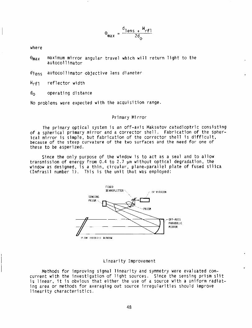
W - dlens + rfl ‘max - 2d0
where
emax maximum mirror angular travel which will return light to the autocol 1 i mator
dlens autocoll imator objective lens diameter
Wrfl ref 1 ector width
d 0 operating distance
No problems were expected with the acquisition range.
Primary Mirror
The primary optical system is an off-axis Maksutov catadioptric consisting Fabrication of the spher- of a spherical primary mirror and a corrector shell.
ical mirror is simple, but fabrication of the corrector shell is difficult, because o f the steep curvature of the two surfaces and the need for one of these to be asperized.
Since the only purpose o f the window is to act as a seal and to allow transmission o f energy from 0.4 to 2.7 pm without optical degradation, the window as designed, is a thin, circular, plane-parallel plate of fused silica (Infrasil number 1). This is the unit that was employed:
F I X E D BEAMSPL ITTER-\., r T V V I D I C O N
OFF-AXIS PARABOL IC MIRROR
- 1’1 ANI I’AIMI I I I W1NI)OW
Linearity Improvement
Methods for improving signal linearity and symmetry were evaluated con- current with the investigation o f light sources. Since the sensing prism slit is linear, it is obvious that either the use o f a source with a uniform radiat- ing area or methods for averaging out source irregularities should improve linearity characteristics.
48

The i n i t i a l s t e p was to e v a l u a t e t h e source-lamp re imag ing scheme. T h i s c o u l d incandescent f i l a m e n t s t r u c t u r e and make For i n f r a r e d t r a n s m i s s i o n , energy loss i n t h i s f e a t u r e makes i t q u i t e u n f e a s i b l e .
use o f f i b e r o p t i c s as p a r t o f t h e e l i m i n a t e i r r e g u l a r i t i e s i n t h e amp- f i lament a l i g n m e n t u n c r i t i c a l . t h e channels c o u l d be s u b s t a n t i a l -
A r e v i e w o f v a r i o u s t ypes o f t u n g s t e n f i l a m e n t lamps l e d t o t h e c h o i c e o f a r i b b o n f i l a m e n t as t h e source. Thus, t h e r i b b o n f i l a m e n t was chosen to ach ieve t h e l i n e a r i t y and symmetry based on i t s t empera tu re v a r i a t i o n s . Sys t e s t s conducted a t 800 f t ( i d e a l weather c o n d i t i o n s ) showed t h a t t h e a u t o c o l mator was l i n e a r and symmetr ica l t o *15 a rc -sec .
em 1 -
AUTOCOLLIMATOR MEASURING CHARACTERISTICS
The a u t o c o l l i m a t o r measur ing c h a r a c t e r i s t i c s , when m o n i t o r i n g a mirror, a r e determined b a s i c a l l y by t h e a u t o c o l l i m a t o r a p e r t u r e , t h e r e f l e c t o r aper- t u r e , and t h e o p e r a t i n g d i s t a n c e . The a n g u l a r a c q u i s i t i o n range B t o t a l f o r an i d e a l a u t o c o l l i m a t o r i s
- d~ + 'rfl
' t o t a l - 2d0
where
dA a u t o c o l l i m a t o r a p e r t u r e
Wrfl r e f 1 ector w i d t h
do o p e r a t i n g d i s t a n c e
The a u t o c o l l i m a t o r i s capable o f m o n i t o r i n g t h e t r a n s l a t i o n o f a re t ro- re f lec to r and i n t h i s sense has an a c q u i s i t i o n and m o n i t o r i n g range whose c h a r a c t e r i s t i c s a r e c o n t r o l l e d o n l y by t h e a u t o c o l l i m a t o r a p e r t u r e , source c o n f i g u r a t i o n , t a r g e t s i z e , o p e r a t i n g range, a u t o c o l l i m a t o r v i g n e t t i n g , and d e t e c t o r c o n f i g u r a t i o n . There i s no image m o t i o n a t t h e f o c a l p l a n e when t h e t a r g e t p r i s m i s t r a n s l a t e d , b u t o n l y changes i n t h e energy c o n t e n t o f t h e image. I t i s t h e un ique comb ina t ion o f source c o n f i g u r a t i o n , r e t r o r e f l e c t o r , and d e t e c t o r s t h a t g i v e s t h e a u t o c o l l i m a t o r t h e c a p a b i l i t y o f measur ing p r i s m t r a n s l a t i o n .
Ana
PENTA MIRROR ROTATION ERRORS I N A SINGLE-AXIS
yses o f t h e autocollimator/Denta/roof-Drism s
ALIGNMENT SYSTEM
n g l e - a x i s a l i g n m e n t s y s t e m i n d i c a t e d t h a t r e a d i n g s a r e i n s e n s i t i v e t o pen ta r o t a t i o n s abou t two o r t h o g o n a l axes. When t h e pen ta i s r o t a t e d by t h e ang le Y about i t s e x i t r a y , t h e az imuth r e a d i n g i s o n l y i n e r r o r by -Y* , p r o v i d e d t h e r o o f p r i s m cap tu res t h e c e n t e r o f t h e a u t o c o l l i m a t o r beam. t h e o p t i c a l az imuth-a l ignment system.)
* (See t h e f o l l o w i n g s k e t c h of
49

The autocollimator measures angular rotations I3 of the roof prism about the L-axis. The penta mirror or optical square is used to deflect the auto- collimator line of sight by 90° or to allow parallel translation of the line of sight. The autocollimator measurements may be disturbed by rotations of the deflecting device. A penta mirror is chosen as a deflector because rotations of the penta mirror about its principal axis (the Z-axis when X = Y = 0) will not cause error deviations of the line of sight nor introduce errors in the autocollimator readings.
Penta rotations may also occur about the X- and Y-axes analyses indicated that
(1) Penta rotation about the X-axis produces no signif the center of the autocollimator return image and therefore significant errors in the readings.
and mathematical
cant deviation of introduces no
(2) Penta rotation about the Y-axis does produce deviations. For example, Let the penta let the autocollimator monitor a roof prism rotation of angle A.
be rotated by the angle Y about the Y-axis, and by the angle X about the X-axis. Let Q equal the autocollimator reading. Then
+ = A - Y 2 (838)
(3) Penta rotation does cause rotation of the autocollimator return image about its center. Let the rotation angle be u. Then
u = 2(X - Y) (839)
( 4 ) No matter how the penta is tilted, rotation about its principle axis Z produces no errors.
These conclusions assume that all elements are large enough to capture the center of the autocollimator beam.
The angles 4 and u have been computed precisely (by Perkin Elmer) from exact formulas to twelve significant figures and have been compared with Q and u computed from simplified formulas (eqs. (838) and (B39)) for various cases of interest. The results from the approximate formulas (eqs. (838 and (B39>) , are quite accurate for the usual small angles encountered when auto- collimators are used. Percentage error is defined as one hundred times the approximate value minus the true value, then divided by the true value.
50

M A T R I X ALGEBRA MODEL
A m a t r i x a l g e b r a model o f t h e a l i g n m e n t s y s t e m was c o n s t r u c t e d f o r ana- l y t i c a l i n v e s t i g a t i o n and programmed f o r d i g i t a l compu ta t i on . I n t h e model, a column m a t r i x or v e c t o r r e p r e s e n t s a geomet r i c r a y ,
- G = [i] (640)
where components Q, m, and n a r e d i r e c t i o n cos ines o f t h e r a y . The r a y has a s i n g l e p o s i t i v e d i r e c t i o n such t h a t t h e r e t u r n r a y a l o n g t h e p a t h taken by G i s -5.
A square m a t r i x M r e p r e s e n t s a p l a n e mirror where a, b , and c a r e t h e d i r e c t i o n cos ines o f a u n i t n o r m a l l y d i r e c t e d ou tward from t h e r e f l e c t i n g s u r f a c e . Then
1 - 2 a 2 -2a; - 2 a j
-2ac -2bc 1-2c
M = -2ab 1-2b -2bc - (841)
R e f l e c t i o n of a r a y G by a p l a n e mirror M i s r e p r e s e n t e d by t h e m a t r i x m u l t i p l i c a t i o n G ' = MG, where 5 ' i s t h e r e f l e c t e d r a y . I f t h e r a y i s f irst r e f l e c t e d by t h e mirror M1 and then r e f l e c t e d by t h e mirror M2, we have
G ' = bllG and GI' = M GI. By t h e a s s o c i a t i v e law fo r m a t r i x m u l t i p l i c a t i o n , we
a l s o have GI' = M2MlG = M1 ,2- G, where M1,2 = M2Ml. Thus i f a r a y undergoes c o n s e c u t i v e r e f l e c t i o n s by t h e sys tem o f p l a n e mirrors M1,M2,.. . , -n, M t h e
sys tem i s r e p r e s e n t e d by t h e m a t r i x bl1,2,..., n.
An o p t i c a l e lement composed o f s e v e r a l p l a n e r e f l e c t i n g su r faces i s t hus r e p r e s e n t e d by a m a t r i x which i s t h e p r o d u c t of t h e m a t r i c e s r e p r e s e n t i n g t h e i n d i v i d u a l p l a n e r e f l e c t i n g s u r f a c e s , t aken i n t h e same o r d e r as t h e o r d e r of r e f l e c t i o n .
-2- -
I n p a r t i c u l a r , a r o o f p r i s m whose roof edge i s p a r a l l e l t o t h e X-ax is 1 s r e p r e s e n t e d by t h e m a t r i x
A pen ta whose p r i n c i p a l a x i s i s p a r a l l e l t o t h e Z-axis i s r e p r e s e n t e d by the
m a t r i x
51

The r o t a t i o n o f a p lane mirror M or o p t i c a l e lement i s r e p r e s e n t e d by the s i m i l a r i t y t r a n s f o r m a t i o n u-ltj IJT where u i s t h e d e s i r e d o r t h o g o n a l r o t a t i o n m a t r i x . For r o t a t i o n s of the ang les X , Y , Z , and A, t h e t r a n s - f o r m a t i o n m a t r i c e s a r e
and
1 0
-X u = [o cos x s i n x 0 - s i n X cos X
cos Y 0 s i n Y
s i n Y 0 cos Y
[ cos z si; z ;] U - - s i n Z cos Z -2 -
0 1
[ co; A si; A p1 uA = - s i n A cos A 0
(844)
(845)
( B46)
(847)
Since the t r a n s f o r m a t i o n m a t r i c e s a r e o r t h o g o n a l , t h e i r i n v e r s e u-1 t o t h e i r t ranspose UT; t h a t i s ,
To l o c a t e t h e a u t o c o l l i m a t o r r e t u r n image, two r a y s must be t r a c e d th rough t h e system. L e t t h e two r a y s be ( 1 ) r a y C o r i g i n a t i n g from t h e c e n t e r o f t h e a u t o c o l l i m a t o r o b j e c t and p a s s i n g th rough t h e o p t i c a l c e n t e r of t h e a u t o c o l l i - mator o b j e c t i v e l e n s and ( 2 ) r a y o r i g i n a t i n g from t h e upper extreme o f t h e a u t o c o l l i m a t o r az imu th o b j e c t and a l s o p a s s i n g th rough t h e o p t i c a l c e n t e r o f the o b j e c t i v e . The a u t o c o l l i m a t o r has i t s l i n e o f s i g h t d i r e c t e d p a r a l l e l t o the n e g a t i v e X-ax is . tends an ang le D a t t h e o b j e c t i v e ; t hus ,
i s equa l u-ly? - U = UTy? u.
The upper h a l f o f t h e a u t o c o l l i m a t o r az imuth o b j e c t sub-
-COS D - C and =[ 0 ]
- s i n D (848)
S ince b o t h o f these r a y s must be r e f l e c t e d t h r o u g h t h e a l i g n m e n t system, i t i s conven ien t t o combine them i n t o one a u t o c o l l i m a t o r m a t r i x - A, where
-COS D
0 - s i n D A = [c,I)] = [i (849)
52
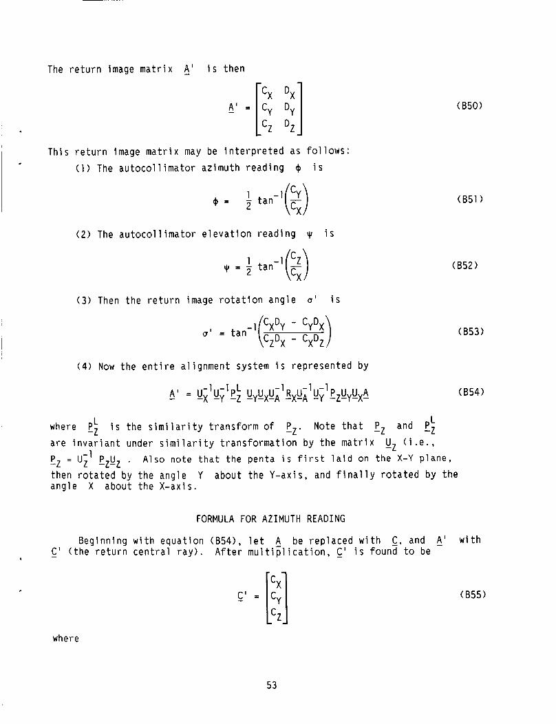
The r e t u r n image m a t r i x A' i s t h e n
A ' = -
T h i s r e t u r n image m a t r i x may be i n t e r p r e t e d as fo l lows: ( 1 ) The a u t o c o l l i m a t o r az imu th r e a d i n g @ i s
( 2 ) The a u t o c o l l i m a t o r e l e v a t i o n r e a d i n g q~ i s
( 3 ) Then t h e r e t u r n image r o t a t i o n a n g l e u' i s
-1 x Y - CYDX = tan (:z:x - CxDz)
( 4 ) Now t h e e n t i r e a l i g n m e n t system i s r e p r e s e n t e d by
(850)
( 8 5 3 )
L L where pz i s t h e s i m i l a r i t y t r a n s f o r m of pz. Note t h a t pz and pz a r e i n v a r i a n t under s i m i l a r i t y t r a n s f o r m a t i o n by t h e m a t r i x uz ( i . e . ,
-1 Pz = Uz pzuz . then r o t a t e d by t h e ang le Y about t h e Y-ax is , and f i n a l l y r o t a t e d by t h e ang le X about t h e X-ax is .
Also note t h a t the penta i s f i r s t l a i d on the X-Y p lane ,
FORMULA FOR A Z I M U T H R E A D I N G
Beg inn ing w i t h e q u a t i o n (B54), l e t A be r e p l a c e d w i t h C , and A' - C ' ( t h e r e t u r n c e n t r a l r a y ) . A f t e r m u l t i p l i c a t i o n , C ' i s found t o be .
where
(854)
w i t h
(855)
53

I , c x = 1 - 2 cos A s in2Y + s i n A cos Y ( s i n x s i n Y - cos ~ 1 2
c y = s i n 2 A cos2X cos2Y - 2 cos Y ( s i n A cos X cos Y + cos A s i n Y )
x [ s i n A s i n X cos Y ( s i n X s i n Y - cos X ) ]
+ cos A s i n Y ( s i n X s i n Y + cos X >
cz = [ 2 cos 2 A s in2Y cos Y(cos X s i n Y - s i n X) - 2 sin2A cos2X C O S ~ Y ]
x (cos X s i n Y + s i n X ) + s i n 2A(1 + 2 s i n 2 Y ) s i n X cos x C O S ~ Y
- s i n Y(I - 2 s in2Y)
The az imuth r e a d i n g + i s t hen g i v e n by e q u a t i o n (B51). I n p a r t i c u l a r , if a l l o f t h e ang les a r e z e r o ,
- C ’ = [SI (856)
which i s t h e case o f p e r f e c t a l i g n m e n t ( n u l l ) .
As a t h i r d - o r d e r a p p r o x i m a t i o n for t h e sma l l ang les n o r m a l l y encountered when a u t o c o l l i m a t o r s a r e used, t h e sma l l a n g l e app rox ima t ions may be s u b s t i t u t e d .
(857
N e g l e c t i n g a l l terms o f o r d e r s g r e a t e r t h a n t h r e e , we have
r 1 - 2A2+ 4AY2 1 C ’ g - I 2 ( A - Y ) ( X - Y ) - A ( X + Y) 2 2
(858)
. We can now f i n d 4 by s u b s t i t u t i n g va lues of C x and Cy from e q u a t i o n (858) i n t o e q u a t i o n (B51) and u s i n g t h e t h i r d - o r d e r terms t o measure t h e error i n assuming t h e second-order a p p r o x i m a t i o n e q u a t i o n (838) .
54
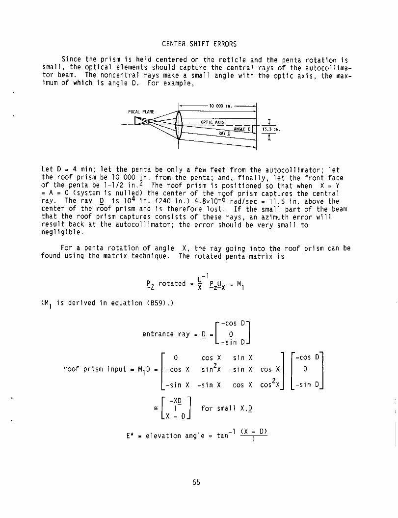
CENTER S H I F T ERRORS
Since t h e p r i s m i s h e l d c e n t e r e d on t h e r e t i c l e and t h e p e n t a r o t a t i o n i s s m a l l , t h e o p t i c a l e lements shou ld c a p t u r e the c e n t r a l r a y s o f t h e a u t o c o l l i m a - tor beam. The n o n c e n t r a l r a y s make a sma l l ang le w i t h t h e o p t i c a x i s , t h e max- imum o f which i s a n g l e D. For example,
10 ooo I N , - FOCAL PLANE c
OPTIC A X I S - - - - -__ --
L
L e t D = 4 min; l e t t h e pen ta be o n l y a few f e e t from t h e a u t o c o l l i m a t o r ; l e t t h e r o o f p r i s m be 10 000 i n . from t h e pen ta ; and, f i n a l l y , l e t t h e f r o n t face o f t h e pen ta be 1-112 i n . 2 The roof p r i s m i s p o s i t i o n e d so t h a t when X = Y = A = 0 ( s y s t e m i s n u l l e d ) t h e c e n t e r o f t h e roof p r i s m c a p t u r e s t h e c e n t r a l r a y . The r a y 0 i s l o 4 i n . (240 i n . ) 4 . 8 ~ 1 0 - 6 r a d / s e c = 11.5 i n . above t h e c e n t e r of t h e roof p r i s m and i s t h e r e f o r e l os t . I f t h e smal l p a r t o f t h e beam t h a t t h e roof p r i s m c a p t u r e s c o n s i s t s o f these r a y s , an az imuth e r r o r w i l l r e s u l t back a t t h e a u t o c o l l i m a t o r ; t h e error should be v e r y smal l t o n e g l i g i b l e .
For a penta r o t a t i o n o f a n g l e X , t h e r a y g o i n g i n t o t h e roof p r i s m can be found u s i n g the m a t r i x t e c h n i q u e . The r o t a t e d pen ta m a t r i x i s
I ,-1 - P z r o t a t e d = pzUx = M1
(M1 i s d e r i v e d i n e q u a t i o n ( B 5 9 ) . >
en t rance r a y = - D =
0 cos X s i n X -COS D
roof p r i s m i n p u t = MID = -cos x sin2X - s i n x cos x] [ 0 ] 2
- s i n X - s i n X cos X cos X - s i n D
- 1 ( X - D) 1 E * = e l e v a t i o n a n g l e = t a n
55

For D = 0 ( c e n t r a l r a y ) ,
Now r a y D subtends an ang le D w i t h r e s p e c t t o t h e o p t i c a x i s . If t he pen ta i s r o t a t e d an ang le X about t h e X-axis, t h i s r e s u l t s i n r a y D go ing th rough t h e roof pr i sm, back i n t o t h e pen ta p r i s m and g i v i n g an o u t p u f az imuth r e a d i n g even though a n g l e A = 0. (See t h e f o l l o w i n g ske tch . )
RAY MISSES PRISM
\YR COORDINATE
X
I To f i n d i t s magnitude we r o t a t e t h e pen ta th rough an ang le X t o g i v e t h e
I 1 pen ta m a t r i x M1 = l& pzux. Thus,
= M D = i n p u t t o roof p r i s m D l 1-
0 = R D = o u t p u t o f roof p r i s m -2 -x-1
1 L D' = LJi pz uxD2 = o u t p u t o f p e n t a d e s i r e d I
The re fo re ,
, - D ' = (
0 0 - s i n X cos X
( 8 5 9 ) 1 0 cos x s i n X
- s i n X cos X 2 s i n X 2 - s i n X - s i n X cos X cos x
1 M1 = U- P U = -x -z-x L
r o cos x s i n X 1 s i n X cos X J sXM1 = L c o s x - s i n 2 x
2 s i n X s i n X cos X -cos X
56
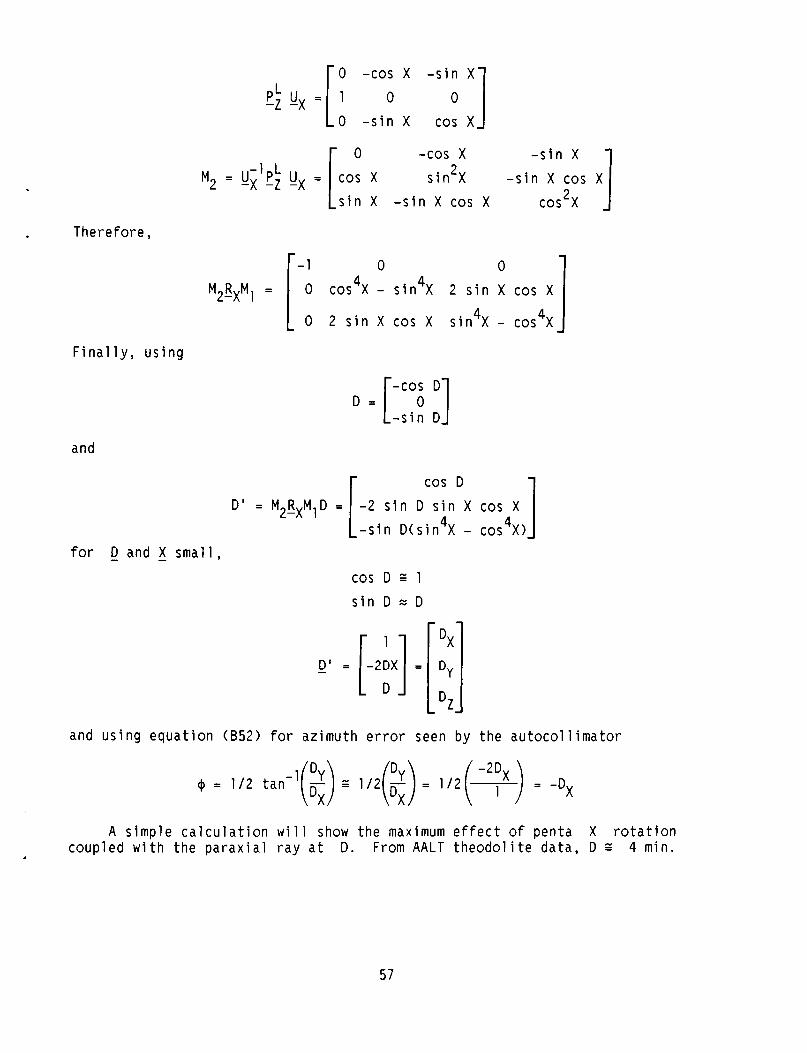
There fo re ,
0 -cos X - s i n X
0 - s i n X cos X
-z P L u = [ l -x 0
-cos x - s i n X
- s i n X cos X 2
s i n X - s i n X cos X cos x s i n X
2
-1 L M 2 = lJx Pz ux =
0 0
cos X - s i n X 2 s i n X cos X
0 2 s i n X cos X s i n X - cos X
4 4
4 4
F i n a l l y , u s i n g
-COS D D = [ - s i n 0 D ]
and
r cos D 1 D ' = M R M D = -2 s i n D s i n X cos X
4 4 2-x 1 1
- s i n D ( s i n X - cos X > for 0 and 5 s m a l l ,
cos D r 1 s i n D z D
and u s i n g e q u a t i o n (852) f o r az imu th e r r o r seen by t h e a u t o c o l l i m a t o r
A s i m p l e c a l c u l a t i o n w i l l show t h e maximum e f f e c t o f pen ta X r o t a t i o n coup led w i t h t h e p a r a x i a l r a y a t D. From AALT t h e o d o l i t e da ta , D p 4 min.
57
L e t X = 4 min, az imu th e r r o r z -Dx = -X2
= -(1.15x10⁻³ r a d > 2 = -(1.33x10⁻⁶ r a d ) = 0.273 arc-sec
S ince i n p r a c t i c e , t h e pr isms a r e k e p t c e n t e r e d i n t h e f i e l d o f v i e w by t h e sway se rvo loop, t h e maximum pen ta r o t a t i o n b u i l d - u p o f mechanical t o l e r a n c e s ) , t h e a c t u a l error i n c l u d i n g b e a r i n g e c c e n t r i c i t y i s
x i s 220 arc -sec (maximum
-4 ecc z 1 m in = 2 . 9 ~ 1 0 r a d
az imuth e r r o r = -x (ecc) = - ( 1 . 4 6 ~ 1 0 - 4 > ( 2 . 9 ~ 1 0 - 4 > = 4 . 2 ~ 1 0 - 8 r a d = -0.009 arc-sec (wh ich can be n e g l e c t e d )
SWAY SERVO ANALYSIS
The s p e c i f i c a t i o n s t o be m e t a r e
( 1 ) Sway d i sp lacemen t = 12 i n . peak ( s i n u s o i d a l ) ( 2 ) Sway f requency 5 0.75 Hz ( 3 ) Sway e r r o r (dynamic) 2 314 i n . ( 4 ) Porro p r i s m mounted on C e n t a u r ' s I M G p l a t f o r m ( 5 ) A t sway n u l l , equa l amounts o f b o t h phases imp inge on t h e sway d e t e c t o r
Assuming p e r f e c t square-wave chopp ing and ba lance , t h e ac s i g n a l from t h e d e t e c t o r i s z e r o . There i s a dc s i g n a l p r e s e n t r e s u l t i n g from t h e energy i n t h e d e t e c t o r b u t t h i s i s n o t a m p l i f i e d by t h e ac p r e a m p l i f i e r . When t h e sway p r i s m t r a n s l a t e s , t h e energy from one phase i n c r e a s e s w h i l e ene rgy i n t h e o t h e r phase decreases.
The amp l i t ude o f t h e ac component i n d i c a t e s how much t h e p r i s m has t r a n s - l a t e d . The phase (phase I or I1 i n c r e a s i n g ) i n d i c a t e s i n wh ich d i r e c t i o n t h e Porro p r i s m has moved - l e f t or r i g h t .
A s t h e v e h i c l e t r a n s l a t e s , an er ror s i g n a l o f t h e p r o p e r phase i s gener- a t e d so as t o d r i v e t h e p e n t a c a r r i a g e t o e s t a b l i s h a new n u l l p o s i t i o n . The penta c a r r i a g e i s d r i v e n by a motor th rough a Saginaw r e c i r c u l a t i n g b a l l and l e a d s c r e w u n i t . T h i s u n i t conve r t s t h e r o t a r y m o t i o n o f t h e motor t o t h e l i n e a r mo t ion r e q u i r e d f o r t h e pen ta w i t h a t y p i c a l e f f i c i e n c y exceed ing 85 p e r c e n t . The l e a d s c r e w has a 1 : l conve rs ion r a t i o ; one comple te r e v o l u t i o n o f the s h a f t p roduc ing 1 i n . of l i n e a r d i sp lacemen t . D r i v e f o r c e i s p r o v i d e d by the dc v o l t a g e a p p l i e d t o t h e motor c i r c u i t a rmature .
S ince t h e f i e l d o f t h e motor i s s u p p l i e d by a permanent magnet, t h e o n l y way o f c o n t r o l l i n g t h e armature c u r r e n t or developed t o r q u e i n v o l v e s v a r y i n g the d c v o l t a g e a p p l i e d t o t h e motor's a rmature t e r m i n a l s .
58
The requ i remen t f o r l a r g e peak and t r a n s i e n t c u r r e n t s u t i l i z i n g method o f c o n t r o l has p resen ted a p rob lem i n t h e p a s t . Wi th t h e ava of high-power S C R ' s and t r a n s i s t o r s , t h i s i s no l onger a problem.
t h i s l a b i 1 i t y
The i n i t i a l i n v e s t i g a t i o n l e d t o t h e c o n s i d e r a t i o n o f u s i n g N A S A ' s 28 Vdc l i n e for t h e p r i m a r y power source . t r a n s i e n t requ i remen ts of 40 A , and average requ i remen ts of 8 A d u r i n g t r a c k i n g would n e c e s s i t a t e t h e use o f heavy-duty connec to rs , r e l a y s , and o t h e r compo- n e n t s . I n a d d i t i o n , i f a dc supp ly i s used, t h e c o n t r o l of SCR elements becomes d i f f i c u l t because a means o f commutating t h e SCR must be p r o v i d e d . S i l i c o n power t r a n s i s t o r s c o u l d be u t i l i z e d , b u t t h e l a r g e peak c u r r e n t s would n e c e s s i t a t e l a r g e power t r a n s i s t o r s w i t h t h e a t t e n d a n t requ i remen ts o f hea t s i n k s and d r i v e r a m p l i f i e r s . Wi th o n l y a s i n g l e p o l a r i t y v o l t a g e a v a i l a b l e , a s w i t c h i n g arrangement would have t o be p r o v i d e d t o r e v e r s e t h e motor.
u l a t e d ac s y s t e m f o r t h e se rvo a m p l i f i e r . advantages:
l i n e c u r r e n t w i l l be l e s s f o r a g i v e n power o u t p u t . A t r a n s f o r m e r s teps t h e 115-Vac v o l t a g e down t o t h e 20 V r m s r e q u i r e d f o r t h e motor.
i t i e s , thus d o i n g away w i t h t h e n e c e s s i t y for a complex s w i t c h i n g arrangement.
However, t h e l a r g e c u r r e n t d r a i n s , peak
For the f o r e g o i n g reasons , i t was dec ided t o i n v e s t i g a t e t h e use o f a mod- An ac system p r o v i d e s a number o f
( 1 ) Because o f t h e h i g h e r l i n e v o l t a g e , 115 Vac i n s t e a d o f 28 vdc , t h e ac
( 2 ) The center - tapped t rans fo rmer e a s i l y p r o v i d e s b o t h v o l t a g e p o l a r -
(3) Because of t h e r e v e r s i n g n a t u r e of t h e ac v o l t a g e , S C R ' s can be used w i t h o u t t h e n e c e s s i t y for commutat ing c i r c u i t s .
There a r e two t ypes of c o n t r o l dev i ces t h a t can be used i n a modu la ted ac system - s i l i c o n power t r a n s i s t o r s and S C R ' s . have t h r e e main advantages o v e r t h e S C R ' s .
The s i l i c o n power t r a n s i s t o r s
( 1 ) I n h e r e n t t u r n - o f f c a p a b i l i t y ( 2 ) S l i g h t l y l ower s a t u r a t i o n v o l t a g e (3) Higher f requency c a p a b i l i t i e s
I n a 400-cyc le system, t h e f i r s t and t h i r d advantages a r e o b v i a t e d , and i t becomes necessa ry o n l y t o c o n s i d e r t h e s a t u r a t i o n v o l t a g e s .
Now, t h e SCR has t h r e e p r i m a r y advantages o v e r t h e power t r a n s i s t o r :
( 1 ) H ighe r v o l t a g e c a p a b i l i t y f o r a g i v e n power l e v e l
( 2 ) H ighe r peak t r a n s i e n t and r m s c u r r e n t c a p a b i l i t i e s , combined w i t h
(3) Very s e n s i t i v e g a t e a c t i o n - smal l d r i v e c u r r e n t r e q u i r e d , u s u a l l y n o
S ince t h e ac v o l t a g e s p r e s e n t a r e low ( 2 8 t o 42 V peak), t h e h i g h e r v o l t - age c a p a b i l i t y o f t h e SCR i s n o t a p r i m a r y advantage as t h e r e a r e s u i t a b l e s i l i c o n power t r a n s i s t o r s a v a i l a b l e . The SCR, t hen , possesses two main advan- tages : ( 1 ) t h e a b i l i t y t o w i t h s t a n d l a r g e t r a n s i e n t c u r r e n t s and ( 2 ) t h e
h i gh-vol t age capabi 1 i t y
need f o r p r e - d r i v e n stages

ex t reme ly h i g h g a i n l ow-ga te -d r i ve requ i remen ts . t i o n v o l t a g e s f o r t r a n s i s t o r s would be a f a c t o r t o c o n s i d e r i n e x t r e m e l y low v o l t a g e c i r c u i t s , b u t f o r t h e ac v o l t a g e s p r e s e n t , t h e h i g h e r v o l t a g e d rop o f t h e SCR i s n o t a p rob lem - thus , SCR's shou ld be t h e c o n t r o l e lement for our sys tem.
l i n e . f a c t u r e d by Sprague E l e c t r i c and known as S i l i c o n t r o l . i t s two S C R ' s p r o v i d e f u l l - w a v e o p e r a t i o n o f one v o l t a g e p o l a r i t y . f u l l -wave c o n t r o l u n i t i s a l s o needed t o p r o v i d e t h e o p p o s i t e p o l a r i t y v o l t a g e . The amount o f phase s h i f t of t h e ga ted p u l s e i s p r o p o r t i o n a l t o t h e d r i v e c u r - r e n t . t h e phase ang le , i t i s p r o p o r t i o n a l t o t h e s i n e of t w i c e t h e phase ang le p l u s t h e ang le i t s e l f . Therefore a l i n e a r r e l a t i o n s h i p does n o t e x i s t between d r i v e v o l t a g e i n t o t h e g a t i n g u n i t s and SCR average o u t p u t v o l t a g e . ana lyses , t h e e f f e c t of t h i s d e p a r t u r e from a l i n e a r r e l a t i o n s h i p i s assumed t o be smal l fo r smal l phase ang les .
The advantage o f low sa tu ra -
S C R ' s o p e r a t e most e f f i c i e n t l y when d r i v e n b y p u l s e s synch ron ized t o t h e The pu lses a r e p r o v i d e d a phase s h i f t i n g s a t u r a b l e r e a c t o r u n i t manu-
One " S i l i c o n t r o l " and Another
The average v o l t a g e developed by t h e S C R ' s i s n o t l i n e a r l y r e l a t e d t o
For purposes of
- Ea ! ~- I I
The T i tan /Centaur and A t l a s I C e n t a u r Sway Servo system has one ma jo r and two minor feedback l oops . (See t h e f o l l o w i n g s k e t c h . )
- I I I
I L------ _ _ _ _ _ _ _ _ _ _ _ J
G(s) ( 1 + 0.00125S)
-1 I I I I I I I
-J
The two minor l oops serve t o s t a b i l i z e t h e o p e r a t i o n a l a m p l i f i e r , reduce t h e n o n l i n e a r i t y o f t h e SCR d r i v e , and p r o v i d e a l ower source impedance as seen b y t h e motor. T h i s l a s t o b j e c t i v e i s necessary because S C R ' s appear as v e r y h i g h impedances when i n t h e nonconduc t ing s t a t e . These h i g h impedances would a l l o w t h e motor t o c o a s t i n o r d i n a t e l y u n l e s s o t h e r means were p r o v i d e d to damp i t .
To f a c i l i t a t e a n a l y s i s , we can reduce t h e e lements i n b l o c k s A and B t o a s i m p l i f i e d e q u i v a l e n t form.
B l o c k B, which r e p r e s e n t s t h e motor and i t s a s s o c i a t e d i n e r t i a l o a d , can be reduced t o one t r a n s f e r f u n c t i o n :
60

where
KB motor back e l e c t r o m o t i v e f o r c e (EMF) c o n s t a n t ; 0.108 V / rad /sec
57 a R t o t t o t a l a rmature r e s i s t a n c e ; 0
FB v i scous f r i c t i o n l o a d ; 1 . 5 8 ~
KT t o r q u e c o n s t a n t ; K ~ l 1 . 3 6 = 0
0-3 1 b - f t / r a d / s e c
080 1 b - f t / A
Tmech mechanical t i m e Cons tan t ; 0.140 sec
Te lec
Th is t r a n s f e r f u n c t i o n (eq . (860) can now be s i m p l i f i e d t o
motor e l e c t r i c a l t i m e c o n s t a n t ; 50x10-6 sec
9.28 8 - 0.104 - Ea S ( l + 0.140S>(1 + ~ O X ~ O - ~ S )
For t h e l e a d screw, t h e c o n v e r s i o n f a c t o r i s
= 24ad ( f o r d i n f e e t ) %ad
Ea S ( l + 0.140S)(1 + 5 0 ~ 1 0 - ~ S >
1.18 -6 = G(S)B lock B - d
Ea S(I + 0.140S)(1 + 50x10 S ) - -
B l o c k A , which comprises t h e feedback and compensat ion l o o p s , can be reduced t o a s l m p l i f i e d t r a n s f e r f u n c t i o n . a t i o n a l a m p l i f i e r ne twork , f o r example,
The t r a n s f e r f u n c t i o n for an oper -
61

I
m u -20
-30
INPUT NETWORK C r--------
\ \
- \ \ \ \ \ - \
\ \
'12A '12B
where
Y 1 2 A s h o r t - c i r c u
Y12B s h o r t - c i r c u
t t r a n s f e r adm
t t r a n s f e r adm
t t a n c e o f feedback ne twork A
t t a n c e o f feedback ne twork B
Y12c
E v a l u a t i o n o f these ne tworks i s f a i r l y t e d i o u s , complex, and prone t o e r ro r . Perkin-Elmer u t i l i z e d i t s Perk in -E lmer C i r c u i t A n a l y s i s Program (PECAP) com- p u t e r program t o o b t a i n t h e f r e q u e n c y c h a r a c t e r i s t i c s o f t h e ne twork . b reak f r e q u e n c i e s o b t a i n e d from t h e f r e q u e n c y c h a r a c t e r i s t i c s were t h e n con- v e r t e d t o t h e system t i m e c o n s t a n t s .
s h o r t - c i r c u i t t r a n s f e r admi t tance o f i n p u t ne twork C
The
The s o l i d l i n e r e p r e s e n t s t h e f requency d a t a genera ted b y t h e computer. The d o t t e d l i n e s r e p r e s e n t t h e asymptotes t o t h e f requency response cu rve .
62
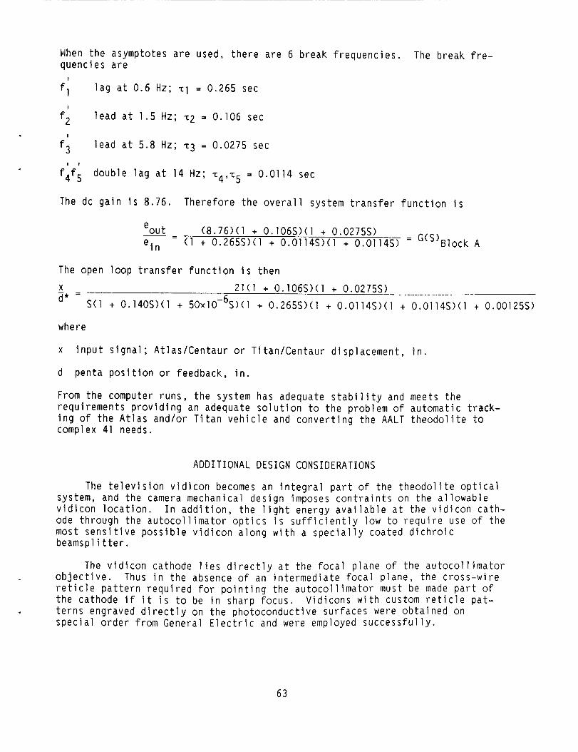
When the asymptotes are used, there are 6 break frequencies. quencies are
lag at 0.6 Hz; TI = 0.265 sec
lead at 1.5 Hz; ~2 = 0.106 sec
lead at 5.8 Hz; ~3 = 0.0275 sec
double lag at 14 Hz; T ~ , - c ~ = 0.0114 sec
The break fre-
I
f l
f2
f3
I
I
I 1
f4f5
The dc gain is 8.76. Therefore the overall system transfer function is
eou t e i n
(8.76)(1 + 0.106S>(l + 0.0275s) - - - (1 + 0.265S)(1 + O.O114S>(l + 0.0114s) = G(S)Block A
The open loop transfer function is then - - X 21(1 + 0.106S>(1 + 0.0275s) d* - S(l + 0.140S>(1 + 50~1O-~S)(l + 0.265S>(l + O.O114S>(l + O.O114S)(l + 0.00125S)
where
x input signal; AtlasiCentaur or TitaniCentaur displacement, in.
d penta position or feedback, in.
From the computer runs, the system has adequate stability and meets the requirements providing an adequate solution to the problem of automatic track- ing of the Atlas and/or Titan vehicle and converting the AALT theodolite to complex 41 needs.
ADDITIONAL DESIGN CONSIDERATIONS
The television vidicon becomes an integral part of the theodolite optical system, and the camera mechanical design imposes contraints on the allowable vidicon location. In addition, the light energy available at the vidicon cath- ode through the autocollimator optics is sufficiently low to require use of the most sensitive possible vidicon along with a specially coated dichroic beamspl i tter.
The vidicon cathode lies directly at the focal plane of the autocollimator objective. Thus in the absence of an intermediate focal plane, the cross-wire reticle pattern required for pointing the autocollimator must be made part of the cathode if it is to be in sharp focus. Vidicons with custom reticle pat- terns engraved directly on the photoconductive surfaces were obtained on special order from General Electric and were employed successfully.
63
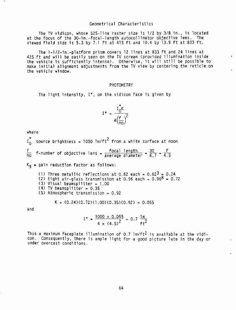
Geomet r i ca l C h a r a c t e r i s t i c s
The TV v i d i c o n , whose 5 2 5 - l i n e r a s t e r s i z e i s 1 / 2 by 3 / 8 i n . , i s l o c a t e d a t t h e f o c u s o f t h e 3 0 - i n . - f o c a l - l e n g t h a u t o c o l l i m a t o r o b j e c t i v e l e n s . The viewed f i e l d s i z e i s 5.3 by 7.1 f t a t 415 f t and 10.4 by 13.9 f t a t 833 f t .
The 1 - 1 / 2 - i n . - p l a t f o r m p r i s m cove rs 12 l i n e s a t 833 f t and 24 l i n e s a t 425 f t and w i l l be e a s i l y seen on t h e TV screen ( p r o v i d e d i l l u m i n a t i o n i n s i d e t h e v e h i c l e i s s u f f i c i e n t l y i n t e n s e ) . O the rw ise , i t w i l l s t i l l be p o s s i b l e t o make i n i t i a l a l i g n m e n t ad jus tmen ts from t h e TV v iew by c e n t e r i n g t h e r e t i c l e on t h e v e h i c l e window.
PHOTOMETRY
The l i g h t i n t e n s i t y , I * , on t h e v i d i c o n f a c e i s g i v e n by
where 2 source b r i g h t n e s s = 1000 l m / f t from a w h i t e s u r f a c e a t noon
* Io f f o c a l l e n t h - 30 - f - f-number of o b j e c t i v e l e n s = average diaieter - 6.7 - 4 .5 no
Kg = g a i n r e d u c t i o n f a c t o r as f o l l o w s :
( 1 ) Three m e t a l l i c r e f l e c t i o n s a t 0.62 each = 0.623 = 0.24 ( 2 ) E i g h t a i r - g l a s s t r a n s m i s s i o n a t 0.96 each = 0.968 = 0.72 (3) V i s u a l b e a m s p l i t t e r = 1.00 ( 4 ) TV b e a m s p l i t t e r = 0.35 (5 ) Atmospher ic t r a n s m i s s i o n = 0.92
K = (0.24>(0.72>(1.00)(0.35)(0.92) = 0.055 and
1000 x 0.055 l m I * = = 0 . 7 - 4 x (4 .5 ) f t2
Thus a maximum f a c e p l a t e i l l u m i n a t i o n o f 0.7 l m / f t 2 i s a v a i l a b l e a t t h e v i d i - con. under o v e r c a s t c o n d i t i o n s .
Consequent ly, t h e r e i s ample l i g h t f o r a good p i c t u r e l a t e i n t h e day or
64
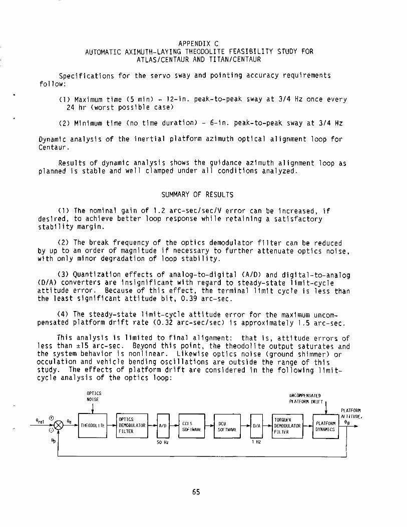
APPENDIX C AUTOMATIC AXIMUTH-LAYING THEODOLITE FEASIBILITY STUDY FOR
ATLAS/CENTAUR AND T ITAN/CENTAUR
S p e c i f i c a t i o n s f o r the s e r v o sway and p o i n t i n g accu racy r e q u i r e m e n t s
( 1 ) Maximum t i m e ( 5 min) - 12- in . peak-to-peak sway a t 3 / 4 Hz once e v e r y
(2 ) Minimum t i m e (no t i m e d u r a t i o n ) - 6 - in . peak-to-peak sway a t 3 / 4 Hz
Dynamic a n a l y s i s o f t h e i n e r t i a l p l a t f o r m az imu th o p t i c a l a l i g n m e n t l o o p f o r
f o l low:
24 h r (worst p o s s i b l e case)
THEODOLITE %et
Centaur.
R e s u l t s o f dynamic a n a l y s i s shows t h e gu idance planned i s s t a b l e and w e l l clamped under a l l c o n d i t
I ALTITUDE. PLATFORM & DYNAMICS
OPTICS TORQUER
F I L T E R SOFTWARE SOFTWARE + D/A ---c DEMODULATOR - + DEMODULATOR + A/D 4 ccLs - DCU
F ILTER
SUMMARY OF RESULTS
( 1 ) The nominal g a i n o f 1.2 a rc -sec /sec /V e r r 0
- A
az imu th a l i g n m e n t l o o p as ons ana lyzed .
%
can be i nc reased . i f
50 HZ 1 Hz
d e s i r e d , t o ach ieve b e t t e r l o o p response w h i l e r e t a i n i n g a s a t i s f a c t o r y s t a b i 1 i t y marg in .
(2 ) The break f requency of t h e o p t i c s demodulator f i l t e r can be reduced by up t o an o r d e r o f magnitude i f necessary t o f u r t h e r a t t e n u a t e o p t i c s n o i s e , w i t h o n l y minor d e g r a d a t i o n o f l o o p s t a b i l i t y .
(3 ) Q u a n t i z a t i o n e f f e c t s o f a n a l o g - t o - d i g i t a l ( A I D > and d i g i t a l - t o - a n a l o g ( D / A ) c o n v e r t e r s a r e i n s i g n i f i c a n t w i t h r e g a r d t o s t e a d y - s t a t e l i m i t - c y c l e a t t i t u d e e r r o r . Because o f t h i s e f f e c t , t h e t e r m i n a l l i m i t c y c l e i s l e s s than t h e l e a s t s i g n i f i c a n t a t t i t u d e b i t , 0.39 arc -sec .
( 4 ) The s t e a d y - s t a t e l i m i t - c y c l e a t t i t u d e e r r o r for t h e maximum uncom-
Th is a n a l y s i s i s l i m i t e d t o f i n a l a l i g n m e n t : t h a t i s , a t t i t u d e e r r o r s o f Beyond t h i s p o i n t , t h e t h e o d o l i t e o u t p u t s a t u r a t e s and
pensated p l a t f o r m d r i f t r a t e (0.32 a rc -sec /sec ) i s a p p r o x i m a t e l y 1 .5 a rc -sec .
l e s s than 215 arc -sec . t h e system b e h a v i o r i s n o n l i n e a r . o c c u l a t i o n and v e h i c l e bend ing o s c i l l a t i o n s a r e o u t s i d e t h e range o f t h i s s tudy . c y c l e a n a l y s i s o f t h e o p t i c s l o o p :
L i k e w i s e o p t i c s n o i s e (g round shimmer) or
The e f f e c t s of p l a t f o r m d r i f t a r e c o n s i d e r e d i n t h e f o l l o w i n g l i m i t -

The autotheodolite is used to sense error between the platform azimuth gimbal and the established launch site reference azimuth. The autotheodolite electro-optical system converts the azimuth misalignment in a dc analog error signal. See the following example, in which it is assumed that misalignment is independent of frequency:
rror
Optics Demodulator/Noise Filter
The filter phase and gain characteristics were determined from manufacturer-supplied data. The approximation is good with maximum errors o f approximately loo and 2 dB at the higher frequencies.
Data has been approximated by a fifth-order lag.
Analog-to-Digital Converter
The function o f the analog-to-digital ( A / D ) converter is to accept the
The bit
filtered dc error voltage and on command produce a binary number in the computer-controlled launch set (CCLS) input register. an input range of 210 V and is an &bit (7 bits + sign) converter. value of the least significant bit is 10 Vdc/z7 = 0.078 vdc which iS equivalent to an attitude error of 0.39 arc-sec. - Note: maximum input signal is only 2 3 Vdc ( 2 1 5 arc-sec), whereas the A/D input range is 210 Vdc.
The A/D converter has
CCLS SOFTWARE
CCLS software attitude error signal is input at the rate of 50 Hz. CCLS communicates to the digital computer unit (DCU) at a l-Hz rate. put, for an attitude error less than 215 arc-sec is given by
The CCLS out-
1 4
Yn = * ( x i + x i - 1 + . . . + x i -49
where
Yn CCLS output on the nth cycle ( 1 Hz)
66
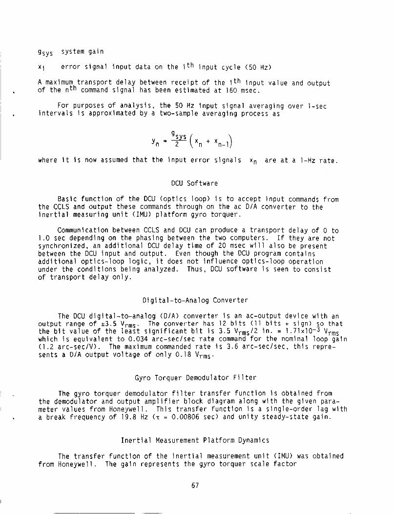
gsys system g a i n
X i
A maximum t r a n s p o r t d e l a y between r e c e i p t o f the i t h i n p u t v a l u e and o u t p u t
e r r o r s i g n a l i n p u t d a t a on t h e i th i n p u t c y c l e (50 Hz)
I o f t h e n t h command s i g n a l has been e s t i m a t e d a t 160 msec.
For purposes of a n a l y s i s , t h e 50 Hz i n p u t s i g n a l a v e r a g i n g over l - s e c i n t e r v a l s i s approx imated by a two-sample a v e r a g i n g process as
n- 1
where i t i s now assumed t h a t t h e i n p u t e r r o r s i g n a l s Xn a r e a t a l-Hz r a t e .
DCU So f tware
Bas ic f u n c t i o n o f t h e DCU ( o p t i c s l o o p ) i s to accep t i n p u t commands from t h e CCLS and o u t p u t these commands th rough on t h e ac D / A c o n v e r t e r t o the i n e r t i a l measur ing u n i t ( I M U ) p l a t f o r m g y r o t o r q u e r .
Communication between CCLS and DCU can produce a t r a n s p o r t d e l a y o f 0 to 1.0 sec depending on t h e phas ing between t h e two computers. synch ron ized , an a d d i t i o n a l DCU d e l a y t i m e of 20 msec w i l l a l s o be p r e s e n t between t h e DCU i n p u t and o u t p u t . Even though t h e DCU program c o n t a i n s a d d i t i o n a l o p t i c s - l o o p l o g i c , i t does n o t i n f l u e n c e o p t i c s - l o o p o p e r a t i o n under t h e c o n d i t i o n s b e i n g ana lyzed . Thus, DCU so f tware i s seen t o c o n s i s t o f t r a n s p o r t d e l a y o n l y .
I f t h e y a r e n o t
D i g i t a l - t o - A n a l o g Conver te r
The DCU d i g i t a l - t o - a n a l o g ( D / A ) c o n v e r t e r i s an ac -ou tpu t dev i ce w i t h an o u t p u t range o f 2 3 . 5 V r m s . The c o n v e r t e r has 12 b i t s ( 1 1 b i t s + s i g n ) so t h a t t h e b i t v a l u e o f t h e l e a s t s i g n i f i c a n t b i t i s 3 .5 Vrms/2 i n . = 1 . 7 1 ~ 1 0 - 3 V r m s wh ich i s e q u i v a l e n t t o 0.034 a rc -sec /sec r a t e command for t h e nominal l o o p g a i n (1 .2 a r c - s e c / V > . The maximum commanded r a t e i s 3.6 a rc -sec /sec , t h i s r e p r e - sen ts a D / A o u t p u t v o l t a g e o f o n l y 0.18 V r m s .
Gyro Torquer Demodulator F i l t e r
The g y r o t o r q u e r demodulator f i l t e r t r a n s f e r f u n c t i o n i s o b t a i n e d from t h e demodu la to r and o u t p u t a m p l i f i e r b l o c k d iagram a l o n g w i t h t h e g i v e n para- meter va lues from Honeywel l . T h i s t r a n s f e r f u n c t i o n i s a s i n g l e - o r d e r l a g w i t h a b r e a k f requency o f 19.8 Hz (T = 0.00806 sec) and u n i t y s t e a d y - s t a t e g a i n .
I n e r t i a l Measurement P l a t f o r m Dynamics
The t r a n s f e r f u n c t i o n o f t h e i n e r t i a l measurement u n i t (IMU) was o b t a i n e d from Honeywel l . The g a i n r e p r e s e n t s t h e g y r o t o r q u e r s c a l e f a c t o r
67

where
w f r equency = 255 rad /sec (40 .6 Hz)
5 damping r a t i o = 0 .65
gv v e l o c i t y g a i n = 2 0 l / s e c .
OPTICS DEMODULATOR WD THEOWL I TE CCLS CCLS
s/w DELAY HOLD DCU sm DELAY HOLD FILTER - 1 - exp(-AtlS) 1 - exp(-At2S)
S exp( - tD ,S) - 1.0 - exp(tD2S) - K ( z q 9 + . . .+Zo)
50zq9 S L
50 HZ i GYRO TORQUER
I
I 1 HZ
ROOT LOCUS A N A L Y S I S
S t a b i l i t y o f t h e h y b r i d l o o p was ana lyzed u s i n g t h e s t a t e v a r i a b l e approach; t h a t i s , s t a b i l i t y i s assured i f t h e roots o f t h e system s t a t e - t r a n s i t i o n m a t r i x a r e w i t h i n t h e u n i t c i r c l e i n t h e complex p l a n e ( u s i n g t h e Z-plane root l o c u s d iag rams) . by d i v e r g e n t o s c i l l a t i o n s and those i n s i d e by decay ing o s c i l l a t i o n s . c o n t r o l f requency and damping r a t i o a r e summarized as fo l lows:
Roots o u t s i d e t h e u n i t c i r c l e a r e c h a r a c t e r i z e d Loop
68
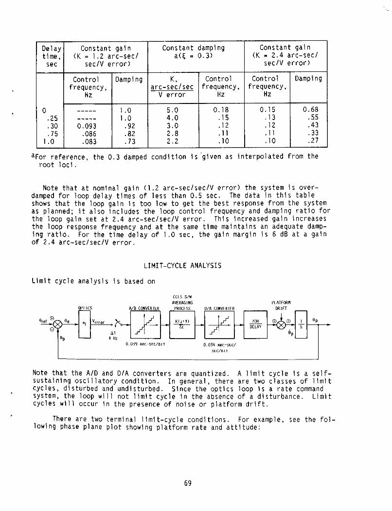
a
C o n t r o l f requency ,
HZ
----- ----- 0.093
.086
.083
Del ay t ime ,
sec
Damping
1 .o 1 .o
.92
.82
.73
0 .25 .30 .75
1 .o
~~
5 .O 4.0 3 .0 2 . 8 2.2
0.18 .15 .12 .ll .10
Cons tan t damping a ( c = 0 .3 )
0 .15 .13 .12 .ll .10
Cons tan t g a i n ( K = 2 .4 a rc -sec /
sec/V e r r o r )
0.68 .55 .43 .33 .27
I
K. I C o n t r o l I C o n t r o l I Damping . - a rc -sec /sec I f requency , I freq;;ncy, I
V e r r o r Hz
:or r e f e r e n c e , t he 0 .3 damped c o n d i t i o n i s ' g i v e n as i n t e r p o l a t e d from t h e root l o c i .
Note t h a t a t nominal g a i n (1 .2 a rc -sec /sec /V e r r o r ) t h e system i s o v e r - damped fo r l o o p d e l a y t imes of l e s s than 0 .5 sec. The d a t a i n t h i s t a b l e shows t h a t t he l oop g a i n i s too low t o g e t t h e b e s t response from t h e system as p lanned; i t a l s o i n c l u d e s t h e l o o p c o n t r o l f requency and damping r a t i o for t h e l o o p g a i n s e t a t 2 . 4 a rc -sec /sec /V er ror . T h i s i n c r e a s e d g a i n i n c r e a s e s t h e l o o p response f requency and a t t h e same t i m e m a i n t a i n s an adequate damp- i n g r a t i o . For t h e t i m e d e l a y o f 1.0 sec, t h e g a i n marg in i s 6 dB a t a g a i n of 2.4 a rc -sec /sec /V e r r o r .
LIMIT-CYCLE ANALYSIS
L i m i t c y c l e a n a l y s i s i s based on
CCLS s/w AVERAGING PLATFORM
OPTICS A/D CONVERTER PROCESS D/A CONVERTER D R I F T
DELAY S
A t e P 1 Hz
0.039 ARC-SEC/BIT 0.034 ARC-SEC/
SEC/BIT
Note t h a t t h e A / D and D / A c o n v e r t e r s a r e quan t i zed . A l i m i t c y c l e i s a s e l f - s u s t a i n i n g o s c i 1 l a t o r y c o n d i t i o n . I n g e n e r a l , t h e r e a r e two c l a s s e s of 1 i m i t c y c l e s , d i s t u r b e d and u n d i s t u r b e d . S ince t h e o p t i c s l o o p i s a r a t e command system, t h e l oop w i l l n o t l i m i t c y c l e i n t h e absence of a d i s t u r b a n c e . L i m i t c y c l e s w i l l occu r i n t h e presence o f n o i s e or pl .at form d r i f t .
l o w i n g phase p lane p l o t showing p l a t f o r m r a t e and a t t i t u d e : There a r e two t e r m i n a l l i m i t - c y c l e c o n d i t i o n s . For example, see t h e f o l -
69

ARC
- -.4 - . 8
NEGATIVE PLATFORM DRIFT. t D = 1.0 SEC
OP *
S E C
. 3
.2
. 1
-.l T7 I
- . 2 !l
Two cases a r e d e p i c t e d : The f irst c o n d i t and t h e second shows p o s i t i v e p l a t f o r m d r whether a c q u i s i t i o n o c c u r s from t h e p o s i t cases, i t i s assumed t h a t t h e p l a t f o r m d r
ARC-!
POSl T I V E PLATFORM DRIFT. t D = 1.0 SEC
OP *
- - . 4 - . 8
/SEC
- . 3
- .2
- . 1
,- L I M I T CYCLE y ' A R C - S E C
- - . 2
on shows n e g a t i v e p l a t f o r m d r i f t , f t . These l i m i t c y c l e s wou ld o c c u r ve or n e g a t i v e d i r e c t i o n s . I n b o t h f t r a t e i s s m a l l .
The l i m i t - c y c l e f r e q u e n c i e s a r e dependent on t h e magn i tude o f t h e d r i f t r a t e . The f r e q u e n c y i n c r e a s e s w i t h an i n c r e a s i n g d r i f t r a t e . The two l i m i t c y c l e s shown assume d r i f t r a t e s o f l e s s t h a n 0.102 arc -sec /sec and -0.068 arc -sec /sec . A s t h e d r i f t r a t e s exceed these v a l u e s , t h e p l a t f o r m a t t i t u d e w i l l jump t o t h e second a t t i t u d e b i t l e v e l . Fo r t h e h i g h e r d r i f t r a t e s , i t w i l l r e q u i r e an i n c r e a s i n g l y l a r g e r s t e a d y - s t a t e a t t i t u d e error t o b i a s o u t t h e p l a t f o r m d r i f t . a rc -sec /sec (0 .32O/h r> , t h e l i m i t - c y c l e a t t i t u d e becomes a p p r o x i m a t e l y 1 .5 a rc -sec .
For a maximum uncompensated p l a t f o r m d r i f t r a t e o f 0.32
Thus, t h e l i m i t - c y c l e a n a l y s i s shows t h a t t h e l i m i t c y c l e r e s u l t i n g from q u a n t i z a t i o n o f t h e a t t i t u d e error and r a t e command i s i n s i g n i f i c a n t w i t h r e g a r d t o o v e r a l l system per fo rmance. The l i m i t - c y c l e a t t i t u d e p e r t u r b a t i o n r e s u l t i n g from these e f f e c t s i s l e s s t h a n t h e l e a s t s i g n i f i c a n t A / D b i t (0.39 a rc -sec ) . T h i s v a l u e w i l l i n c r e a s e w i t h an i n c r e a s e i n l o o p g a i n . However, t h e l i m i t c y c l e would remain be low t h e 1 - b i t l e v e l even w i t h a g a i n i n c r e a s e o f a f a c t o r o f two. The s t e a d y - s t a t e a t t i t u d e error w i l l a l s o i n c r e a s e as t h e p l a t f o r m d r i f t r a t e i n c r e a s e s .
70
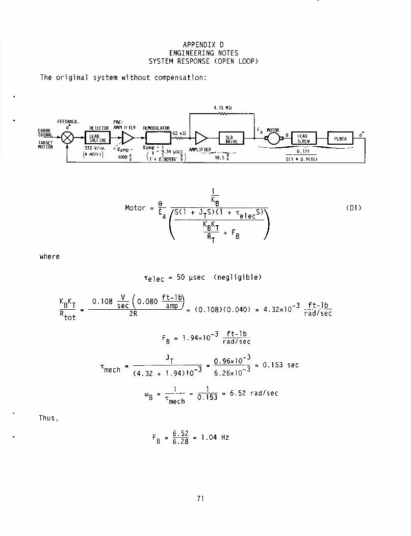
APPENDIX D E N G I N E E R I N G NOTES
SYSTEM RESPONSE (OPEN LOOP)
The o r i g i n a l system w i t h o u t compensat ion:
ERROR
TARGET MOTION
s IG&
FEEDBACK, PRF-
1.15 MR
1 d* DETECTOR ~ G L IFIER DEMODULATOR
v
0.123
S(1 0.153s) --
e KB Ea (’(’ + J ~ ~ ~ ~ ’ + ‘elec
- + FB RT
Motor = -
where
Te lec = 50 psec ( n e g l i g i b l e )
3 f t - l b - - 2R
K ~ K ~ - R t o t
3 f t - l b FB = 1 . 9 4 ~ 1 0 - rad,sec
6.52 r a d l s e c 1 1 0 - - - - - 0.153 = - ‘mech
,
Thus,
F -L_ 52 1.04 Hz B - 6.28 -
7 1
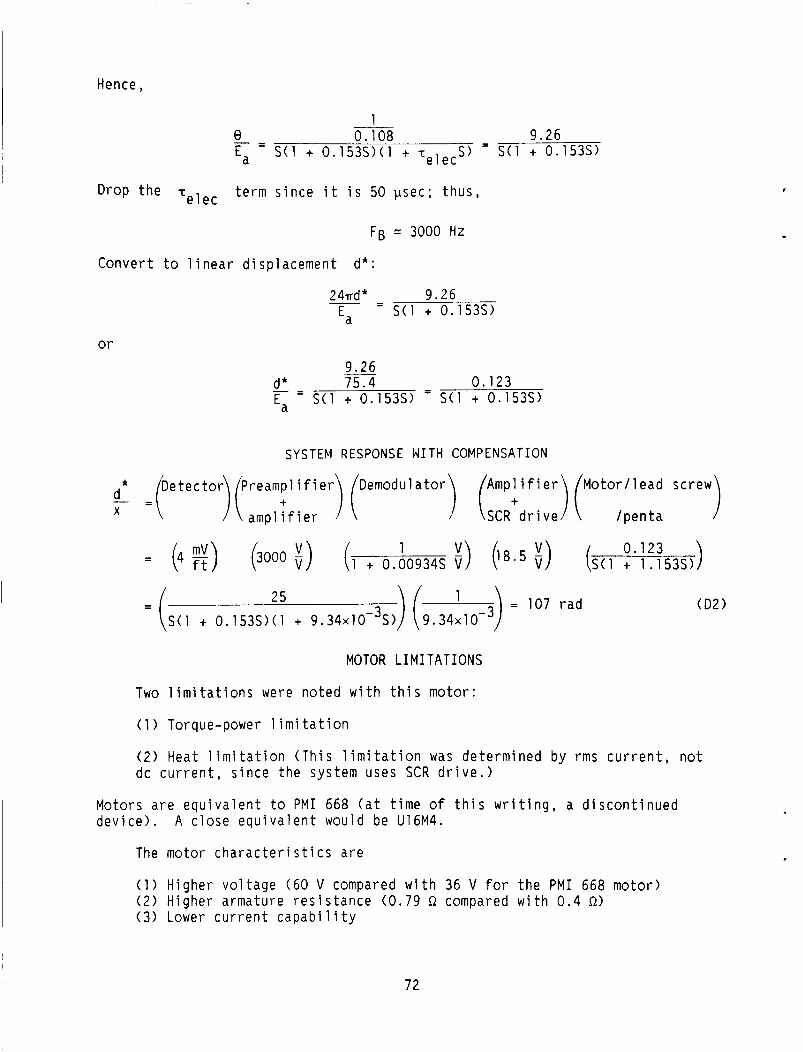
Hence,
1 8 - 0.108 9.26 Ea - S ( l + 0 .153S>( l + - t e l e c S ) = S ( 1 + 0.153s)
Drop t h e -teleC t e r m s i n c e i t i s 50 psec ; t h u s ,
FB = 3000 H Z
Conver t t o 1 i n e a r d isp lacement d* :
2 4wd * 9.26 - - - S ( l + 0.153s) Ea
or 9.26
d* 75.4 - 0.123
Ea - -
- S ( l + 0.153s) - S ( l + 0.153s)
SYSTEM RESPONSE WITH COMPENSATION
* D e t e c t o r P r e a m p l i f i e r Demodulator A m p l i f i e r M o t o r / l e a d screw
- )(amp,Tf ier 1 ( (SCR+drive)( / p e n t a d - - X
1 0.123 = (4 !$) (3000 a) (1 + 0.00934s i) (18.5 i) (S(1 + 1.153s)
25 ) ( 3) = 107 r a d = ( S ( 1 + 0 .153S>( l + 9 . 3 4 ~ 1 O - ~ S ) 9 . 3 4 ~ 1 0 -
(D2)
MOTOR LIMITATIONS
Two l i m i t a t i o n s w e r e no ted w i t h t h i s motor:
(1 ) Torque-power l i m i t a t i o n
( 2 ) Heat l i m i t a t i o n ( T h i s l i m i t a t i o n was de te rm ined by r m s c u r r e n t , n o t dc c u r r e n t , s i n c e t h e system uses SCR d r i v e . )
Motors a r e e q u i v a l e n t t o P M I 668 ( a t t i m e of t h i s w r i t i n g , a d i s c o n t i n u e d dev i ce ) . A c l o s e e q u i v a l e n t would be U16M4.
I The motor c h a r a c t e r i s t i c s a r e c
( 1 ) Higher v o l t a g e (60 V compared w i t h 36 V f o r t h e P M I 668 motor) (2 ) H igher armature r e s i s t a n c e (0 .79 Q compared w i t h 0 . 4 a ) (3 ) Lower c u r r e n t c a p a b i l i t y
72
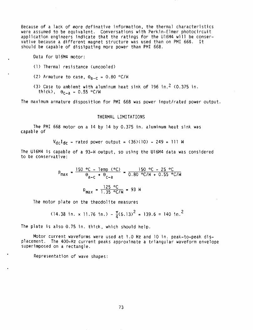
Because o f a l a c k o f more d e f i n a t i v e i n f o r m a t i o n , t h e thermal c h a r a c t e r i s t i c s w e r e assumed t o be e q u i v a l e n t . a p p l i c a t i o n eng ineers i n d i c a t e t h a t t h e r a t i n g s f o r t h e U16M4 w i l l be conser- v a t i v e because a d i f f e r e n t magnet s t r u c t u r e was used than on P M I 668. I t shou ld be capable o f d i s s i p a t i n g more power than P M I 668.
Conversa t i ons w i t h Perk in -E lmer p h o t o c i r c u i t
Data f o r U16M4 motor:
( 1 ) Thermal r e s i s t a n c e (uncoo led )
( 2 ) Armature t o case, = 0 .80 O C / W
(3 ) Case t o ambient w i t h aluminum h e a t s i n k o f 196 i n . 2 (0.375 i n . t h i c k ) , 0c-a = 0.55 O C / W
The maximum armature d i s p o s i t i o n f o r P M I 668 was power i n p u t l r a t e d power o u t p u t .
THERMAL LIMITATIONS
The P M I 668 motor on a 14 by 14 by 0.375 i n . aluminum h e a t s i n k was capab le o f
The U t o be
VdcIdc - r a t e d power o u t p u t = ( 3 6 > ( 1 0 ) - 249 = 1 1 1 W
6M4 i s capable o f a 93-W o u t p u t , so u s i n g t h e U16M4 d a t a was cons c o n s e r v a t i v e :
dered
- 150 O C - Temp ( O C ) - 150 O C - 25 "C 0 + 0c-a - 0.80 O C / W + 0.55 "C/W a- c Pmax -
The motor p l a t e on t h e t h e o d o l i t e measures
2 (14.38 i n . x 11.76 i n . ) - i ( 6 . 1 3 ) ' = 139.6 = 140 i n .
The p l a t e i s a l s o 0.75 i n . t h i c k , wh ich shou ld h e l p .
Motor c u r r e n t waveforms were used a t 1.0 Hz and 10 i n . peak-to-peak d i s - p lacement. superimposed on a r e c t a n g l e .
The 400-Hz c u r r e n t peaks approx imate a t r i a n g u l a r waveform envelope
Represen ta t i on o f wave shapes:
73
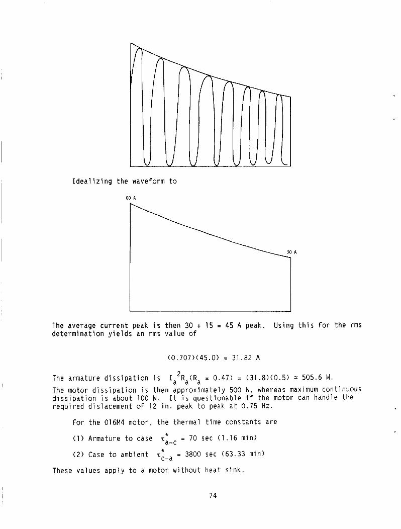
i I d e a l i z i n g t h e waveform t o
60 A
I 3 The average c u r r e n t peak i s t h e n 30 + 15 = 45 A peak. d e t e r m i n a t i o n y i e l d s an r m s v a l u e o f
U s i n g t h i s f o r t h e r m s
( 0 . 7 0 7 > ( 4 5 . 0 > = 31.82 A
The armature d i s s i p a t i o n i s I a 2 R a ( R a = 0 .47) = ( 3 1 . 8 > ( 0 . 5 >
The motor d i s s i p a t i o n i s then a p p r o x i m a t e l y 500 W , whereas maximum cont inuous d i s s i p a t i o n i s about 100 W . r e q u i r e d d i s l a c e m e n t o f 12 i n . peak t o peak a t 0.75 Hz.
505.6 W .
I t i s q u e s t i o n a b l e i f t h e motor can hand le t h e
For t h e 016M4 motor, t h e thermal t i m e c o n s t a n t s a r e
( 1 ) Armature t o case
( 2 ) Case t o ambient
* - c ~ - ~ = 70 sec ( 1 . 1 6 min)
T ~ - ~ = 3800 sec (63.33 min) *
These v a l u e s a p p l y t o a motor w i t h o u t h e a t s i n k .
74
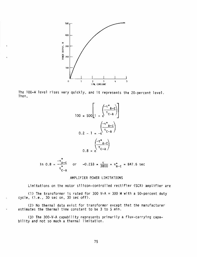
I ’
500
400
3
300 a c a M
g 200 a
100
0 1 2 3 4 5 TIM CONSTANT
The 100-W level rises very quickly, and it represents the 20-percent level. Then,
(Ya-3 c-a 0.8 = E
- L a-c In 0.8 = 7 .r
or - 847.6 sec T -0.233 = - 3800 = ‘i-c - ‘c-a
AMPLIFIER POWER LIMITATIONS
Limitations on the motor silicon-controlled rectifier (SCR) amplifier are
(1) The transformer i s rated for 300 V-A = 300 W with a 50-percent duty cycle, (i.e., 30 sec on, 30 sec off).
( 2 ) No thermal data exist for transformer except that the manufacturer estimates the thermal time constant to be 3 to 5 min.
(3) The 300-V-A capability represents primarily a flux-carrying capa- bility and not so much a thermal limitation.
75
( 4 ) The SCR (2N683) can e a s i l y c a r r y t h e l e v e l o f c u r r e n t w i t h t h e h e a t s i n k i n g employed.
( 5 ) The SCR, 2N683, has a peak fo rward surge o f 200 A . The system p u l l s 7 0 4 peak a t 400 Hz: for t h e fo rward d i r e c t i o n , two for t h e r e v e r s e d i r e c t i o n . Therefore, t h e two fo rward SCR's see on l y a 50-percent d u t y c y c l e ( t h e same s i t u a t i o n as for t h e r e v e r s e SCR's). A d d i t i o n a l l y , t h e two SCR's a r e w i r e d i n a fu l l -wave con f ig - u r a t i o n and, t h e r e f o r e , o n l y c a r r y o n e - h a l f t h e c u r r e n t l o a d . c u r r e n t f low for t h e 2N683 a t 1800 conduc t ion ang le u s i n g t h e 45-A peak average c a l c u l a t e d p r e v i o u s l y i s 0.637 o f peak:
peak r a t i n g i s n o t exceeded. There a r e f o u r SCR's - two
The average
I a v g = (45>(0 .637> = 28.7 A
Bu t each SCR o n l y c a r r i e s h a l f t h e l o a d or 14.35 A . Vendor -supp l ied graph d a t a a r e used: 180° conduc t ion , 15 A , and a s tandard tempera tu re o f 125 OC - y i e l d - i n g an average power o f 22 W .
i s a 6 by 6 by 0.125 i n . copper p l a t e w i t h a 0.75 i n . space between a d j a c e n t S C R ' s a t 20 O C ambient tempera ture .
The suggested p l a t e s i z e f o r t h e h e a t s i n k (14 A average f o r w a r d c u r r e n t )
T h e o d o l i t e S C R ' s a r e mounted t o an aluminum p l a t e 0.125 i n . t h i c k wh ich a l s o houses o t h e r components (e .g . , t rans fo rmer , r a d i o f r e q u e n c y i n t e r f e r e n c e (RFI) f i l t e r , SCR g a t e d r i v e s ) . a p p r e c i a b l e amount o f h e a t as a "concern" i t e m . The t r a n s f o r m e r i s t h e u n i t t h a t d i s s i p a t e s t h e most hea t .
The SCR g a t e d r i v e s do n o t d i s s i p a t e any
The 2N683 w i t h a 0 .003- in . m ica i n s u l a t o r and shear g rease has a thermal impedance o f = 3.1 OC/W (vendor d a t a ) mounted has a s u r f a c e a r e a of 105 i n . 2 (one s i d e ) . usab le s i n c e t h e components p r e v i o u s l y ment ioned a r e a l s o on i t . The s u r f a c e areas of t h e l a r g e r dev i ces a r e
The p l a t e t o wh ich t h e SCR's a r e T h i s i s n o t c o m p l e t e l y
( 1 ) SCR g a t e d r i v e s , two a t 3.375 b y 2 .25 i n . = 8.86 i n . 2 = 17.72 i n . 2 ( 2 ) Transformer and RFI f i l t e r = 9 i n . 2 ( 3 ) Other elements = 10 i n . 2
The t o t a l usab le a r e a (one s i d e ) = 105 i n . 2 - 37 i n . 2 = 68 i n . 2 or 65 i n . 2 b y 0.125 i n . o f aluminum. T h i s i s v e r y c o n s e r v a t i v e .
Transformer d a t a from t h e vendor f o l l o w s :
( 1 ) The u n i t on t h e sway c h a s s i s can s tand 300 V-A c o n t i n u o u s l y .
( 2 ) The thermal t i m e c o n s t a n t i s a p p r o x i m a t e l y 30 min .
(3 ) The t o t a l power l o s s e s a t f u l l power i n c l u d i n g c o r e and copper l osses a re about 13 t o 15 W .
Thus, t h e l i m i t a t i o n i s thermal on t h e 300-V-A t r a n s f o r m e r - n o t f l u x c a p a b i l i t y .
76

.
OUTPUT IMPEDANCE OF MOTOR AMPLIFIER
The a m p l i f i e r was loaded down w i t h r e s i s t i v e l o a d s . Thus, t h e pen ta u n i t was d i s p l a c e d 1.5 i n . t o g i v e f u l l - p o w e r o u t p u t .
r---------- 1
RL * EL, n n
2.0 20.0 4.0 21.0 6.0 21.5 9.0 22.0
- R L l - E L l RL1 + RX EX
A1 so,
- RL2 - EL2 RL2 + RX EX
Thus
RL1 + RX RL2 + RX EX = RL1 E L l = RL2 EL2
or
E L l - EL2
RL2 RL1 (b - b)
or
= 0.31 S I R ~ , avg
ESTIMATED OUTPUT IMPEDANCE ON SERVO
The t o t a l r e s i s t a n c e i n t h e armature c i r c u i t w i l l be a f f e c t e d b y t h e a m p l i f i e r o u t p u t impedance. The v a l u e of 0.31 Q i s much lower t h a n t h a t expected ( 1 . 4 Q). The new t o t a l R t o t w i l l t hen be
7 7

I Rtot = Ra + Rm = 0.31 + 0.57 = 0 .88 0 . 9 Q
was based on an Rtot o f 2 a . KBKr The motor f r i c t i o n a l t e r m R t o t
T h i s now becomes
3 f t - l b = 9 . 6 ~ 1 0 - rad/sec - - KBKr (0.108) (0.080) - 8 . 6 4 ~ 1 0-3 0.9 - 0 . 9 -
R t o t
now becomes mech T
- - J T 0 . 9 6 ~ 1 0 - ~ - - 0 . 9 6 ~ 1 0 - ~ FT - 9.60 + 1 .94 11.54x10⁻³
Tmech = 0.083 SeC O r l /Tmech = 12.05 r a d
T h i s i s about doub le t h e o r i g i n a l computed b reak f r e q u e n c y (0.153 sec a t 6 .5 r a d s ) . made).
(I t i s recommended t h a t a recheck o f a m p l i f i e r o u t p u t impedance be
R e s u l t s on t h e p r e v i o u s t e s t may be i n e r r o r s i n c e h i g h by 0 . 4 a i n each case.
RL, when rechecked, was
D i r e c t c u r r e n t , I, A
0 .055 . l o 5 .215
2 . 4 2 . 8 3.6 4.15 5.2 6 .55 8.2 9.4
Vol tage, v d c
23.68 22.58 22.58 22.52 22.04 21.95 21.80 21.60 21.45 21 .16 20.85 20.60
Load r e s i s t a n c e
a RL 9
W
-390 -200 -1 00
78
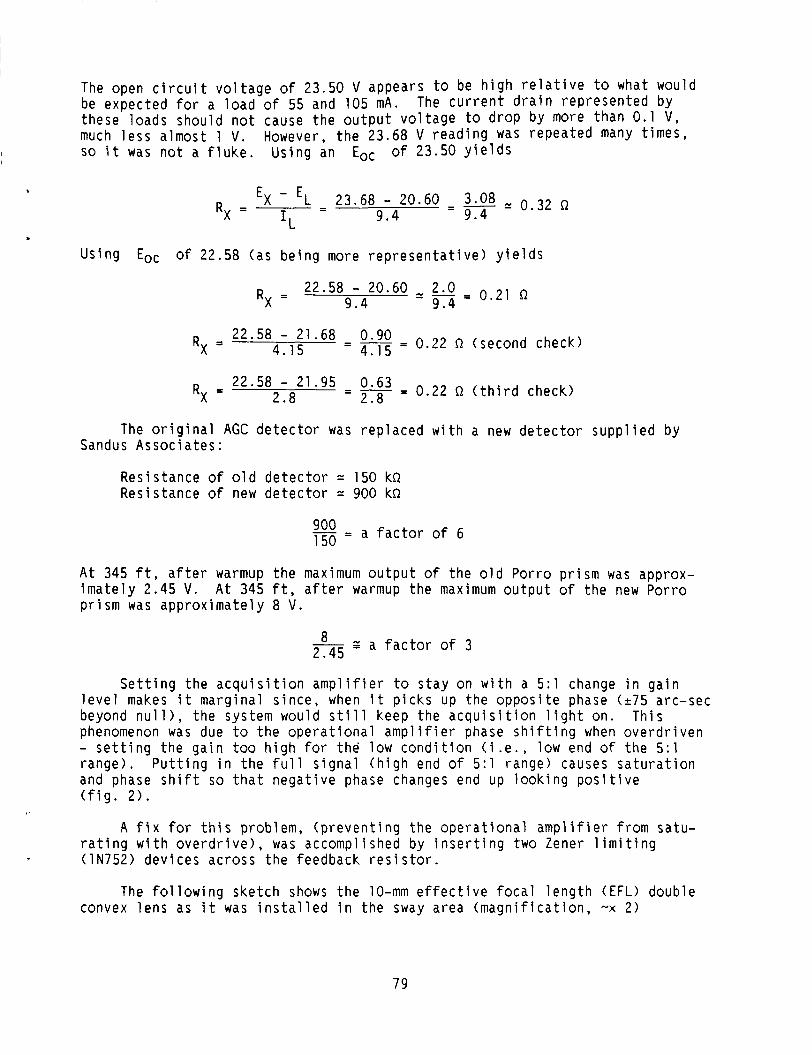
,
The open c i r c u i t v o l t a g e of 23.50 V appears t o be h i g h r e l a t i v e t o what would be expec ted f o r a l o a d of 55 and 105 mA. The c u r r e n t d r a i n r e p r e s e n t e d by these loads shou ld n o t cause t h e o u t p u t v o l t a g e to d r o p by more than 0.1 V , much l e s s a lmost 1 v. SO i t was n o t a f l u k e . Us ing an Eoc o f 23.50 y i e l d s
However, t h e 23.68 V r e a d i n g was repea ted many t i m e s ,
EX - ‘L - 23.68 - 20.60 3.08 = o .32 9 .4 - 9.4 RX = - IL
Us ing Eo, o f 22.58 (as b e i n g more r e p r e s e n t a t i v e ) y i e l d s
22.58 - 20.60 2.0 0.21 a 9 . 4 9 .4 - RX =
2 2 * 5 8 - 2 1 * 6 8 - 0.90 - 0.22 n (second check) 4.15 - 4.15 - RX =
2 2 * 5 8 - 21.95 - 0.63 = 0.22 R ( t h i r d check) RX = 2.8 - 2.8
The o r i g i n a l AGC d e t e c t o r was r e p l a c e d w i t h a new d e t e c t o r s u p p l i e d by Sandus Assoc ia tes :
Res is tance o f o l d d e t e c t o r = 150 kR Res is tance o f new d e t e c t o r = 900 kR
- - goo a f a c t o r o f 6 150 -
A t 345 ft, a f t e r warmup t h e maximum o u t p u t of t h e o l d Porro p r i s m was approx- i m a t e l y 2.45 V. p r i s m was a p p r o x i m a t e l y 8 V .
A t 345 f t, a f t e r warmup t h e maximum o u t p u t o f t h e new Porro
8 z a f a c t o r o f 3 2.45
S e t t i n g t h e a c q u i s i t i o n a m p l i f i e r t o s t a y on w i t h a 5 : l change i n g a i n l e v e l makes i t marg ina l s i n c e , when i t p i c k s up t h e o p p o s i t e phase (275 arc-sec beyond n u l l ) , t h e system would s t i l l keep t h e a c q u i s i t i o n l i g h t on. T h i s phenomenon was due t o t h e o p e r a t i o n a l a m p l i f i e r phase s h i f t i n g when o v e r d r i v e n - s e t t i n g t h e g a i n too h i g h fo r t h e low c o n d i t i o n ( i . e . , low end o f t h e 5 : l r a n g e ) . P u t t i n g i n t h e f u l l s i g n a l ( h i g h end o f 5 : l range) causes s a t u r a t i o n and phase s h i f t so t h a t n e g a t i v e phase changes end up l o o k i n g p o s i t i v e ( f i g . 2 ) .
A f i x for t h i s p rob lem, ( p r e v e n t i n g t h e o p e r a t i o n a l a m p l i f i e r from satu- o v e r d r i v e ) , was accompl ished by i n s e r t i n g two Zener l i m i t i n g ces ac ross t h e feedback r e s i s t o r .
r a t i n g w i t h (1N752) dev
The f o convex l e n s
l o w i n g s k e t c h shows t h e 10-mm e f f e c t i v e f o c a l l e n g t h (EFL) doub le as i t was i n s t a l l e d i n t h e sway a rea ( m a g n i f i c a t i o n , -x 2)
79

The n e x t ske tch shows t h e 10-mm EFL l e n s ( m a g n i f i c a t i o n , 1 : l ) mounted on t h e end o f t h e c e l l :
80

1.60 I N . m
10 MM
The 8.2-kR compensating resistor R6 was reduced t o 4.1 kR since the function o f this resistor was t o reduce the amount of saturation. With Zeners it can be low in value.
I N752 ZENER
The installed AQGC detector is shown with the center mashed down, in the AQGQ position but tied t o the AMGC circuit.
ai
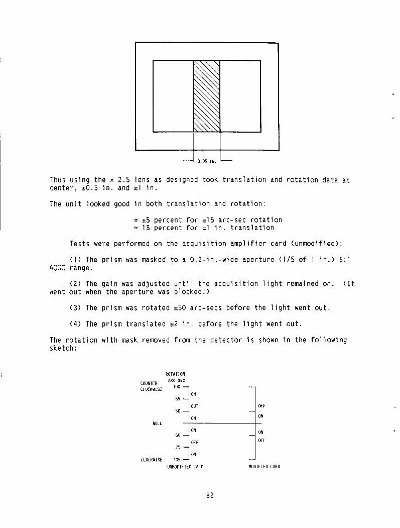
0.05 IN. I- Thus u s i n g t h e x 2.5 l e n s as des igned took t r a n s l a t i o n and r o t a t i o n d a t a a t c e n t e r , 20.5 i n . and 21 i n .
The u n i t l ooked good i n b o t h t r a n s l a t i o n and r o t a t i o n :
= 25 p e r c e n t fo r 215 arc-sec r o t a t i o n = 15 p e r c e n t for 21 i n . translation
Tes ts were per fo rmed on t h e a c q u i s i t i o n a m p l i f i e r c a r d ( u n m o d i f i e d ) :
( 1 ) The p r i s m was masked t o a 0 .2 - i n . -w ide a p e r t u r e (115 o f 1 i n . ) 5 : l
( 2 ) The g a i n was a d j u s t e d u n t i l t h e a c q u i s i t i o n l i g h t remained on. ( I t
(3) The p r i s m was r o t a t e d 250 arc -secs b e f o r e t h e l i g h t went o u t .
( 4 ) The p r i s m t r a n s l a t e d 2 2 i n . b e f o r e t h e l i g h t went o u t .
AQGC range .
went o u t when t h e a p e r t u r e was b locked . )
The r o t a t i o n w i t h mask removed from t h e d e t e c t o r i s shown i n t h e f o l l o w i n g ske tch :
ROTATION. COUNTER.. ARC-SEC
1 ON CLOCKWISE loo
65 -I -] OUT 50 1 OFF
NULL
60
75 j WF ON
CLOCKWISE 105 UNMODIFIED CARD MODIFIED CARD
82

I -
D isp lacement , i n .
0 .25 .50 .75
1 1.5 2 3
,
Demodu la t ion , A m p l i f i e r o u t p u t , vd c vd c
0 0 .25 4.5 .52 9.0 .77 14.0
1 .oo 17.0 1.15 18.5 1.10 17.5
.38 7 .0
The d e m o d u l a t o r - a m p l i f i e r s c a l e f a c t o r check i s shown i n t h i s t a b l e :
( 1 ) The AGC was i n o p e r a t i v e . ( 2 ) The dc v o l t s were taken w i t h a vacuum tube v o l t m e t e r . ( 3 ) The a m p l i f i e r l o a d was a lamp bank d raw ing 6 A .
I f an a l l owance i s made for t h e lamp l o a d i n g , t h e o u t p u t impedance o f t h i s a m p l i f i e r checks f a i r l y w e l l w i t h The a m p l i f i e r / S C R - d r i v e r s c a l e f a c t o r d i scussed p r e v i o u s l y .
SW'AY RESPONSE ( N O I S E COMPENSATION)
The sway s e r v o system i n d i c a t e d t h a t a l a r g e l a g e x i s t e d . The r e s i s t o r - c a p a c i t o r ne twork around t h e o p e r a t i o n a l a m p l i f i e r i s suspec t . The o p e r a t i o n a m p l i f i e r i s connected t o t h e common e m i t t e r s o f t h e t r a n s i s t o r s wh ich d r i v e t h e SCR g a t e c o n t r o l s . The p r i m a r y purpose o f t h e RC ne twork was t o c o n t r o l t h e e f f e c t of i n t e r n a l n o i s e i n t h e system.
Removing t h e c a p a c i t o r and l e a v i n g t h e ne twork open r e s u l t e d i n t h e penta u n i t j i t t e r i n g randomly o v e r a sma l l a m p l i t u d e ( l e s s t h a n 0.125 i n . ) ; no d i s c e r n i b l e f requency components were p r e s e n t , b u t j i t t e r was r a t h e r r a p i d .
The system c o n f i g u r a t i o n looks l i k e t h i s :
+ e 2
R. 1 - 1 3 I
I + e o u t
83
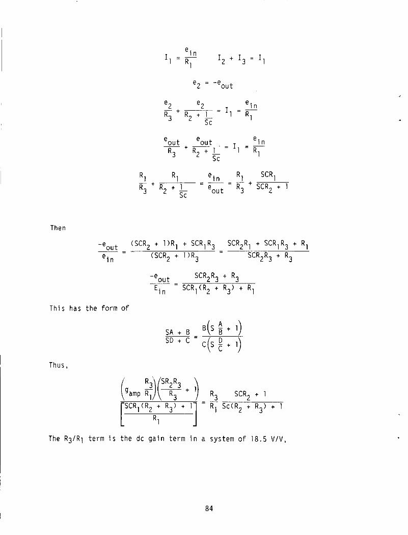
e 2 = -eout
ei n
R 1 = I = - e 2 + - e 2
R 3 R 2 + r s c
SCRl + R 1 - ei n
R 3 R 2 + 1_ eou t - R 1 + R 1 - R3 SCR2 + 1
s c
Then
(SCR2 + l ) R 1 + SCR1R3
(SCR2 + 1 ) R 3
SCR2R, + SCR1R3 + R1
SCR2R3 + R3 - - - - -eo" t -
ei n
-eou t SCR2R3 + R3 - -
Ein - SCR1(R2 + R3) + R 1
Th i s has t h e form of
B(S + 1)
c ( s E + 1)
Thus,
R3 SCR2 + 1
R1 S c ( R 2 + R ) + 1 - - -
3 SCR,(R2 + R3> + 1
The R 3 / R 1 t e r m i s t h e dc g a i n t e r m i n a system o f 18.5 V / V ,
.
84
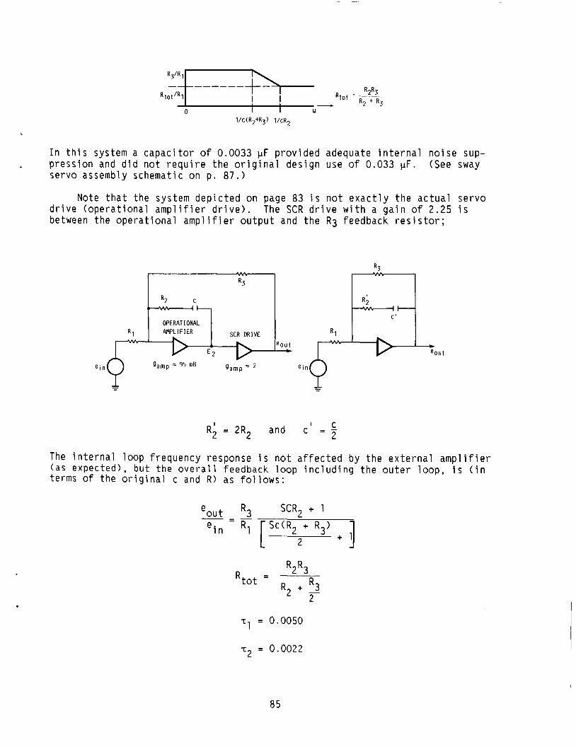
In this system a capacitor of 0.0033 pF provided adequate internal noise sup-
servo assembly schematic on p. 87.) - pression and did not require the original design use of 0.033 pF. (See sway
Note that the system depicted on page 83 is not exactly the actual servo drive (operational amplifier drive). between the operational amplifier output and the R3 feedback resistor;
The SCR drive with a gain of 2.25 is
R 3
t-7 OPERATIONAL R 1
-D-:o"t
' C R; = 2R2 and c - - - 2
The internal loop frequency response is not affected by the external amplifier (as expected), but the overall feedback loop including the outer loop, is (in terms of the original c and R ) as follows:
eout R3 SCR2 + 1 - - - - e i n R 1 [ Sc(R2 + R3) + 3
2
- R2R3 R 2 + R3 Rtot -
- n L
T~ = 0.0050
T2 = 0.0022
85

1 cR2 + 3 R
2
f; =
1 f; = $
R t o t - R3’R1 F- I ] I I
w 1 “2
I The system gain is
-Out e = 18.5 V (7 0 123 a> ft ft 8 8 V = - 20 S n
J
MPLIFIER ‘ 3
REFERENCE
For f’ = 0.1 and w = 0.628,
2o 0.628 = 31.84 = 30 dB
The results on page 88 give 26.5 dB for f ’ = 0.1 Hz. This is a differ- ence of 3.5 dB, a factor of (1.5) time. System gain is then
26.5 dB = 21.13
(21.13)(0.628> = 14.27 14
not 20 as computed.
Since the potentiometer scale factor was measured, the error must be in the amplifier-motor scale factor. imately 70 percent of the completed value:
The system scale factor as measured is approx-
86
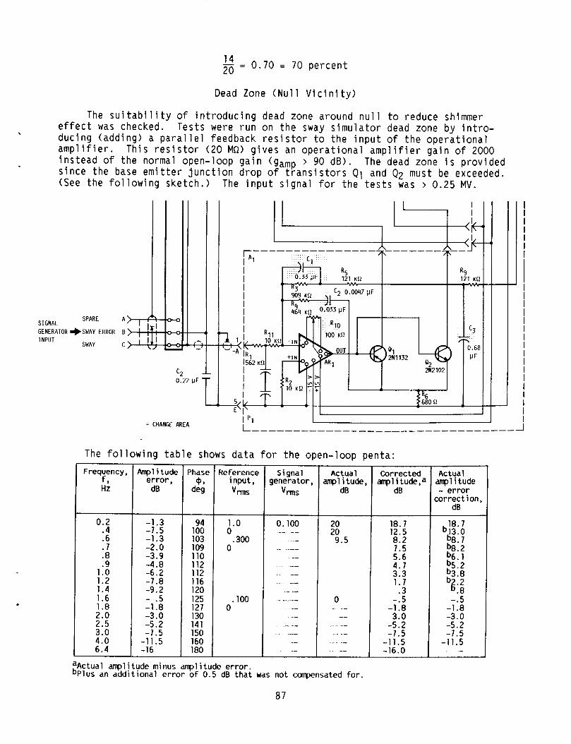
- _ l4 0.70 = 70 p e r c e n t 20 -
Dead Zone ( N u l l V i c i n i t y )
The s u i t a b i l i t y of i n t r o d u c i n g dead zone around n u l l t o reduce shimmer e f f e c t was checked. Tests were r u n on t h e sway s i m u l a t o r dead zone by i n t r o - d u c i n g ( a d d i n g ) a p a r a l l e l feedback res i s to r to t h e i n p u t o f t h e o p e r a t i o n a l a m p l i f i e r . Th i s r e s i s t o r (20 Ma) g i v e s an o p e r a t i o n a l a m p l i f i e r g a i n o f 2000 i n s t e a d of t h e normal open- loop g a i n (gamp > 90 dB) . The dead zone i s p r o v i d e d s i n c e t h e base e m i t t e r j u n c t i o n d r o p o f t r a n s i s t o r s Q1 and Q2 must be exceeded. (See t h e f o l l o w i n g s k e t c h . ) The i n p u t s i g n a l f o r t h e t e s t s was > 0.25 MV.
.
SPARE SIGNAL GENERATOR *SWAY ERROR
SWAY lNPUl
C A I I
= CHANGE AREA I
The f o l l o w i n g t a b l e shows d a t a for t h e open- loop pen ta :
Frequency, f , Hz
0.2 .4 .6 .7 .8 .9
1 .o 1.2 1.4 1.6 1.8 2.0 2.5 3.0 4.0 6.4
Amp1 i tude er ror ,
dB
-1.3 -7.5 -1.3 -2.0 -3.9 -4.8 -6.2 -7.8 -9.2 - .5 -1.8 -3.0 -5.2 -7.5 -1 1.5 -16
94 100 103 109 110 112 112 116 120 125 127 130 141 150 160 180
Reference i npu t , ",S
1 .o 0
0 .300
.loo 0
Actual ampl i tude,
dB
Corrected ampl 1 tude,a
dB
18.7 12.5 8.2 7.5 5.6 4.7 3.3 1.7 .3
-.5 -1.8 3.0 -5.2 -7.5 -11.5 -16.0
Actual anpl i tude - error
correct ion, dB
18.7 b13.0 b8.7 b8.2 b6. 1 b5.2 :3.8
-.5 -1.8 -3.0 -5.2 -7.5
- 1 1.5
2::
.-
aActual ampl itude minus amp1 i tude er ror . bPlus an additional error o f 0.5 dB that was not canpensated for .
87
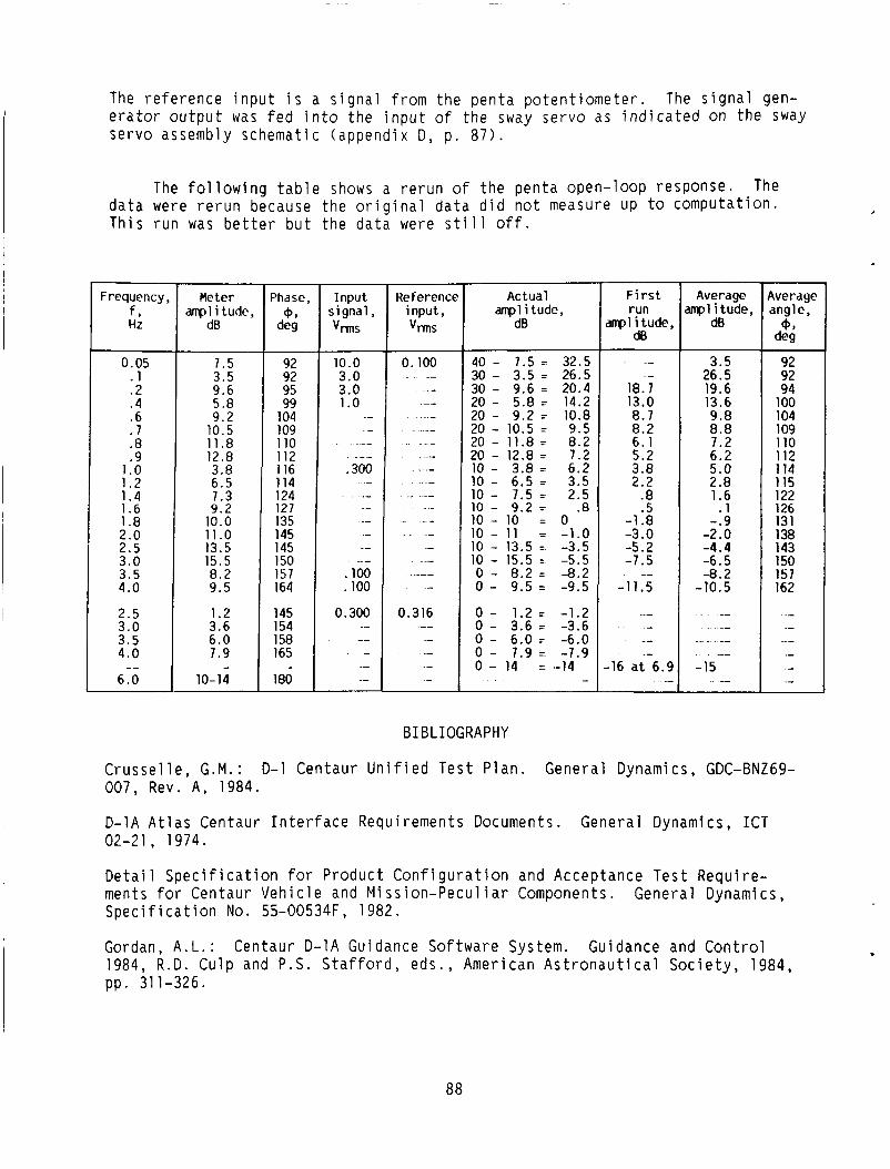
The r e f e r e n c e i n p u t i s a s i g n a l from t h e p e n t a p o t e n t i o m e t e r . The s i g n a l gen- e r a t o r o u t p u t was f e d i n t o t h e i n p u t of t h e sway se rvo as i n d i c a t e d on t h e sway se rvo assembly schematic (appendix D , p . 87) .
The f o l l o w i n g t a b l e shows a r e r u n of t h e pen ta open- loop response. The d a t a were r e r u n because t h e o r i g i n a l d a t a d i d n o t measure up t o compu ta t i on . Th is r u n was b e t t e r b u t t h e d a t a were s t i l l o f f .
Frequency, f, HZ
0.05 . 1 .2 . 4 .6 . 7 .8 .9
1 .o 1.2 1.4 1.6 1.8 2.0 2.5 3.0 3.5 4.0
2.5 3.0 3.5 4.0
6.0 --
Meter amp1 i tude,
dB
7.5 3.5 9.6 5.8 9.2
10.5 11.8 12.8 3.8 6.5 7.3 9.2
10.0 11.0 13.5 15.5 8.2 9.5
1.2 3.6 6.0 7.9
10-14 -
92 92 95 99
104 109 110 112 116 114 124 127 135 145 145 150 157 164
145 154 158 165
180 .-
Input signal, V,S
10.0 3.0 3.0 1 .o
.- - .-
.300
.- _ _ .-
- _-
.loo
. 100
0.300 .- _- - .- .-
Reference Actual input, amp1 i tude,
40 - 7.5 32.5 30 - 3.5 = 26.5 30 - 9.6 = 20.4 20 - 5.8 = 14.2 20 - 9.2 = 10.8 20 - 10.5 = 9.5 20 - 11.8 = 8.2 20 - 12.8 = 7.2 10 - 3.8 = 6.2 10 - 6.5 = 3.5 10 - 7.5 = 2.5 10 - 9.2 z .8 10 - 10 = 0 10 - 11 = -1.0 10 - 13.5 = -3.5 10 - 15.5 = -5.5 0 - 8.2 L- -8.2 0 - 9.5 = -9.5
0 - 1.2 = -1.2 0 - 3.6 = -3.6 0 - 6.0 = -6.0 0 - 7.9 = -7.9 0 - 14 = -14
-
F i r s t run
mpl i tude, dB
- -
18.7 13.0 8.7 8.2 6.1 5.2 3.8 2.2
.8
.5 -1.8 -3.0 -5.2 -1.5
-1 1.5 --
-- _- -- -
-16 a t 6.9 .-
Average mpl i tude,
dB
3.5 26.5 19.6 13.6 9.8 8.8 7.2 6.2 5.0 2.8 1.6
. 1 -.9
-2.0 -4.4 -6.5 -8.2
-10.5
_- .-
._ - -- --
-15 --
Average angle, 0,
de9
92 92 94
100 104 109 110 112 114 115 122 126 131 138 143 150 157 162
.- _- -- .- .- .-
BIBLIOGRAPHY
C r u s s e l l e , G . M . : D-1 Centaur U n i f i e d T e s t P l a n . General Dynamics, GDC-BNZ69- 007, Rev. A , 1984.
D-1A A t l a s Centaur I n t e r f a c e Requirements Documents. General Dynamics, ICT 02-21, 1974.
D e t a i l S p e c i f i c a t i o n f o r P roduc t C o n f i g u r a t i o n and Acceptance T e s t Requ i re - ments f o r Centaur V e h i c l e and M i s s i o n - P e c u l i a r Components. General Dynamics, S p e c i f i c a t i o n No. 55-00534F, 1982.
Gordan, A.L.: Centaur D-1A Guidance So f tware System. Guidance and C o n t r o l 1984, R . D . Cu lp and P . S . S ta f fo rd , eds., American A s t r o n a u t i c a l S o c i e t y , 1984, pp. 311-326.
.
88
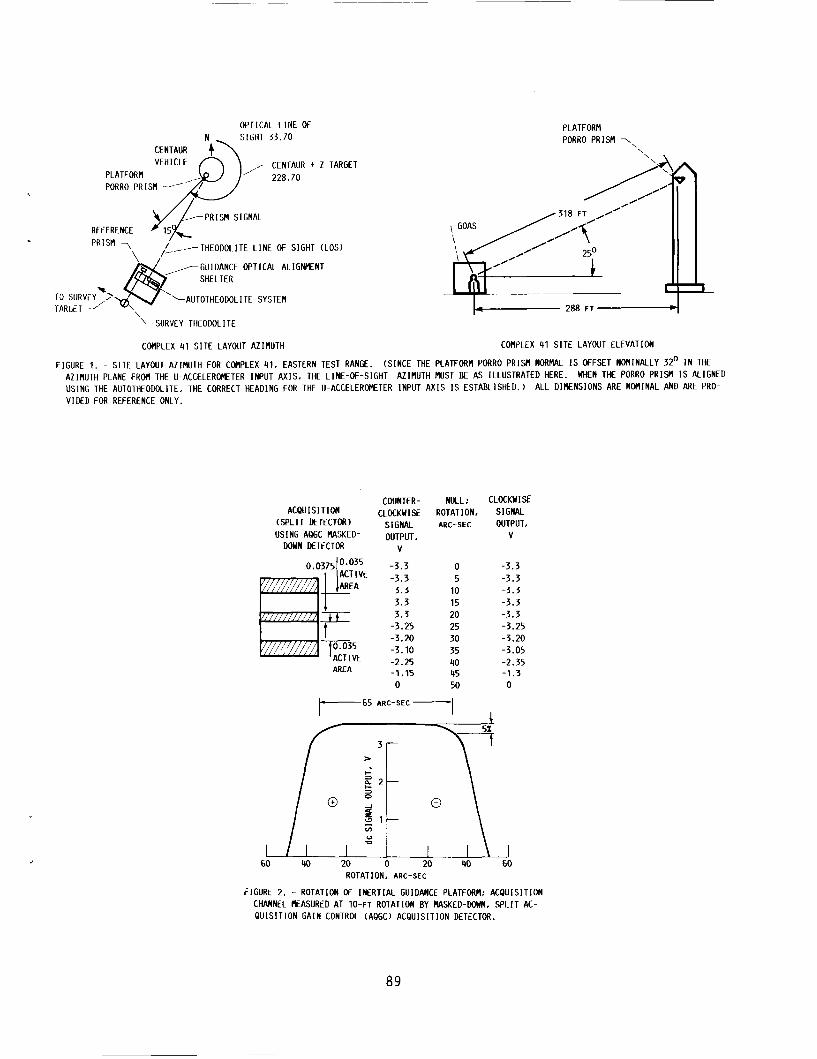
OPTICAL L I N E Of SIGHT 53.70
VEHICLE ,,-CENTAUR + Z TARGEl PLATFORM ' 228.70
-PRISM SIGNAL REFERENCE PRISM
,<,-THEODOLITE L I N E OF SIGHT (LOS) \. ,-GUIDANCE OPTICAL ALIGNMENT
SHELTER
T 3 SURVEY\\ '-AUTOTHEODOLITE SYSTEM
PLATFORM PORRO PRISM 7\
\
288 F T -q '- SURVEY THEODOLITE
COMPLEX 41 S I T E LAYOUT AZIMUTH
FIGURE 1. - S I T E LAYOUT AZINUTH FOR COMPLEX 91, EASTERN TEST RANGE.
COMPLEX 41 S I T E LAYOUT ELEVATION
(SINCE THE PLATFORM PORRO PRISM NORMAL IS OFFSET NOWINALLY 32' I N THE AZIMUTH PLANE FROM THE U-ACCELEROMETER INPUT AXIS, THE LINE-OF-SIGHT USING THE AUTOTHEODOLITE, THE CORRECT HEADING FOR THE U-ACCELEROMETER INPUT A X I S IS ESTABLISHED.)
AZIMUTH MUST BE AS ILLUSTRATED HERE. WHEN THE PORRO PRISM IS ALIGNED ALL DIMENSIONS ARE NOMINAL AND ARE PRO-
V I DED FOR REFERENCE ONLY,
COUNTER- ACPUISl T I ON CLOCKWISE
( S P L I T DETECTOR) SIGNAL USING AQGC MASKED- OUTPUT,
DOWN DETECTOR V
L 60
AREA
3.3 3.3 -3.25 -3.20 -3.10 -2.25 -1.15 0
NULL; CLOCKWISE ROTATION. SIGNAL ARC-SEC OUTPUT.
V
0 -3.3 5 -3.3 10 -3.3 15 -3.3 20 -3.3 25 -3.25 30 -3.20 35 -3.05 40 -2.35 45 -1.3 50 0
r65 ARC-SEC --I I
40 20 0 20 40 60 ROTATION. ARC-SEC
FIGURE 2. - ROTATION OF INERTIAL GUIDANCE PLATFORM; ACQUISITION CHANNEL RASURED AT 10-FT ROTATION BY MASKED-DOWN. S P L I T AC- Q U I S I T I O N GAIN CONTROL (AQGC) ACQUISITION DETECTOR.
89
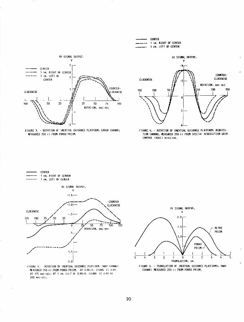
- CENTER --- 1 IN. RIGHT OF CENTER _-- 1 IN. LEFT OF CENTER
1.5
1 .o
d c SIGNAL OUTPUT. V
I 1 I N . RIGHT OF CENTER lr CENTER ---
r RETRO ’ P R I M
PORRO PRISM-’
25 50 7 5 100 25 .#[ ROTATION. ARC-SEC
/’
,/- - - - -- - - - - -,.” .,/ 1.5-
2.0
FIGURE 3. - ROTATION OF INERTIAL GUIDANCE PLATFORM; ERROR CHANNEL MEASURED 250 FT FROM PORRO PRISM.
/ -
-
CENTER 1 IN. RIGHT OF CENTER 1 IN. LEFT OF CENTER
- --- -----
dc SIGNAL OUTPUT. V
COUNTER- CLOCKWISE CLOCKWISE
FIGURE 4. - ROTATION OF INERTIAL GUIDANCE PLATFORM: ACQUISI - T I O N CHANNEL MEASURED 250 FT FROM SPECIAL ACQUISIT ION GAIN CONTROL (AQGC) DETECTOR.
dc SIGNAL OUTPUT. V
90
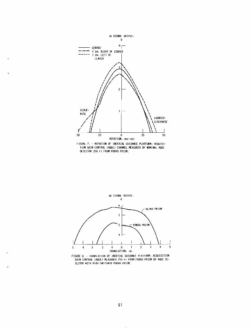
dc SIGNAL OUTPUT, V
CENTER 'I- 1 IN. RIGHT OF CENT 1 IN. LEFT OF
--- ----- CENTER
t
'\ COUNTER- !: \ C L M K W l S E
25 50 ROTATION, ARC-SEC
FIGURE 7. - ROTATION OF INERTIAL GUIDANCE PLATFORM; ACQUISI - T I O N GAIN CONTROL (AQGC) CHANNEL MEASURED BY NOMINAL AQGC DETECTOR 250 FT FROM PORRO PRISM.
dc SIGNAL OUTPUT. v
r RETRO PRISM
/ I t - \
5 4 3 2 1 5 1 2 3 4 5 TRANSLATION, IN.
FIGURE 8. - TRANSLATION OF INERTIAL GUIDANCE PLATFORM; ACQUISIT ION GAIN CONTROL (AQGC) MEASURED 250 F T FROM PORRO PRISM BY AQGC DE- TECTOR WITH BIAS-SWITCHED PORRO PRISM.
91

dc SIGNAL DISTANCE OUTPUT, LEFT OF
v CENTEK.
COUNTER- CLOCKWISE CLOCKWISE
1 .5
- h L
-11 L
-4 L- 1 .o
25 50 75 ROTATION, ARC-SEC
FIGURE 9. - ROTATION OF INERTIAL GUIDANCE PLATFORM. 345 FT FROM PORRO PRISM.
d C SIGNAL OUTPUT, DlSTANCt
V RIGHT OF CENTER,
COUNTER- ’ CLOCKWISE CLOCKWISE
-2
“r
“r
2- CENTER
75 50 25
25 50 75 ROTATION. ARC-SEC
-2 L
FIGURE 10. - ROTATION OF INERTIAL GUIDANCE PLATFORR ERROR CHANNEL EASURED 345 FT FROM PORRO PRISM.
L
92
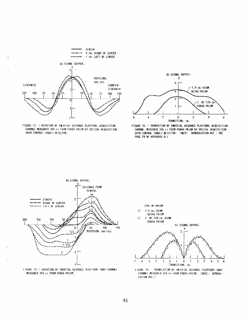
,
CENTER. IN.
CENTER 1 IN. RIGHT OF CENTER 1 IN. LEFT OF CENTER
--- -----
\ I
2 /' '\- -----___-- 0
dc SIGNAL OUTPUT. v
-3 r
2-
7 6 5 4 3 2 1 0 1 2 3 4 5 6
ROTATING, ARC-SEC
COUNTER- CLOCKWISE
CLOCKWISE
125 100 75 50
FIGURE 11. - ROTATION OF INERTIAL GUIDANCE PLATFORM: ACQUISIT ION CHANNEL MEASURED 345 FT FROM PORRO PRISM BY SPECIAL ACQUISIT ION GAIN CONTROL (AQGC) DETECTOR.
dc SIGNAL OUTPUT. V
6 4 2 0 2 4 6 TRANSITION, I N .
FIGURE 12. - TRANSITION OF INERTIAL GUIDANCE PLATFORM: ACQUISIT ION CHANNEL MEASURED 345 FT FROM PORRO PRISM BY SPECIAL ACQUISIT ION GAIN CONTROL (AQGC) DETECTOR. (NOTE: DENODULATION OUT - SEE PAGE 79 OF APPENDIX D . )
93
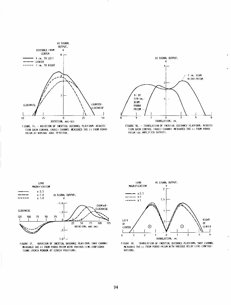
d c SIGNAL OUTPUT,
DISTANCE FROM V CENTER
1 IN. TO LEFT CENTER 1 IN. TO RIGHT
--- -----
dc SIGNAL OUTPUT. V
'r I r ~-IN.-DIAM
ROTATION, ARC-SEC
FIGURE 15, - ROTATION OF INERTIAL GUIDANCE PLATFORM; ACQUISI - T ION GAIN CONTROL (AQGC) CHANNEL MEASURED 3 4 5 FT FROM PORRO PRISM BY NOMINAL AQGC DETECTOR.
TRANSLATION, I N .
FIGURE 16. - TRANSLATION OF INERTIAL GUIDANCE PLATFORM; ACQUISI- T I O N GAIN CONTROL (AQGC) CHANNEL MEASURED 3 4 5 F T FROM PORRO PRISM (dC AMPLIFIER OUTPUT).
LENS MAGNIFICATION
x 2.5
x 1.0 V --- x 2.0 d c SIGNAL OUTPUT -----
LENS d c SIGNAL OUTPUT. MAGNIFICATION V
L
x 2.5 --- x 2 ------ x l 1.5 -1.0-
CLOCKWISE
LEFT RIGHT 25 50 75 100 125 OF
ROTATION. ARC-SEC CENTER .5 -
4 3 2 1 0 1 2 3 4 l . O L TRANSLATION. I N
FIGURE 17. - ROTATION OF INERTIAL GUIDANCE PLATFORM: SWAY CHANNtL FIGURE 18. - TRANSLATION OF INERTIAL GUIDANCE PLATFORM; SWAY CHANNEL EASURED 3 4 5 FT FROM PORRO PRISM WITH VARIOUS LENS CONFIGURA- TIONS (PENTA MIRROR AT CENTER POSITION). RAT IONS .
MEASURED 3 4 5 FT FROM PORRO PRISM WITH VARIOUS RELAY LENS CONFIGU-
94
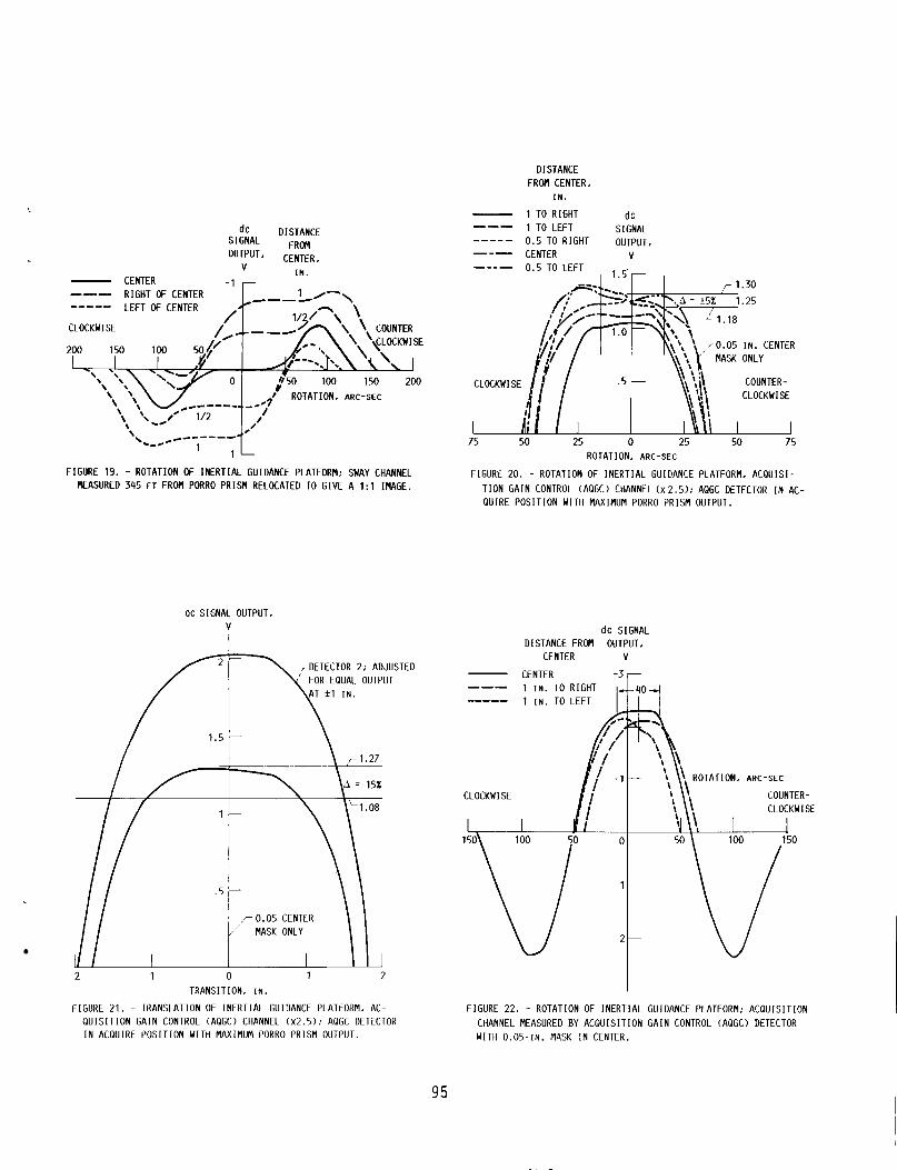
DISTANCE FROM CENTER,
I N .
- 1 TO RIGHT dc 1 TO LEFT 0.5 TO RIGHT OUTPUT, CENTER V
S I GNAL --- - _ _ _ _ --- -_-- 0.5 TO LEFT , l.5.-
dc DISTANCE SIGNAL FROM ou"Tu" CENTER,
v I N . - CENTER -1 r
c- --- RIGHT OF CENTER
/ LEFT OF CENTER -----
/. CLOCKWISE
200 150 100 50.4'
ROTATION. ARC-SEC CL
L 75
OCKW I
r 1.30 - e-1. I I 1.25 -
50 25 0 25
COUNTER-
ROTATION, ARC-SEC
_L 50
FIGURE 19. - ROTATION OF INERTIAL GUIDANCE PLATFORM: SWAY CHANNEL REASURED 345 FT FROM PORRO P R I M RELOCATED TO GIVE A 1:l IHAGE.
FIGURE 20. - ROTATION OF INERTIAL GUIDANCE PLATFORM, ACQUISI- T l O N GAIN CONTROL (AQGC) CHANNEL (X2.5); AQGC DETECTOR I N AC- QUIRE POSITION WITH MAXIMUM PORRO PRISM OUTPUT.
dc SIGNAL OUTPUT. V
I ,DETECTOR 2; ADJUSTED
FOR EQUAL OUTPUT
I I \ 71.27
I A = 15%
\'L 1 .08
1 2
dc SIGNAL DISTANCE FROM OUTPUT,
CENTER V
-3 - CENTER --- 1 IN. TO RIGHT ----- 1 IN. TO LEFT
COUNTER- CLOCKWISE
CLOCKW I S€
I
TRANSITION. IN. I FIGURE 21. - TRANSLATION OF INERTIAL GUIDANCE PLATFORM. AC- FIGURE 22. - ROTATION OF INERTIAL GUIDANCE PLATFORM; ACQUISIT ION
Q U I S l T l O N GAIN CONTROL (AQGC) CHANNEL (~2.5); AQGC DETECTOR CHANNEL MEASURED BY ACQUISIT ION GAIN CONTROL (AQGC) DETECTOR I N ACQUIRE POSITION WITH MAXIMUM PORRO PRISM OUTPUT. WITH 0.05-IN. MASK I N CENTER.
95

dc SIGNAL OUTPUT. V
2 -
1 -
TRANSLATION. I N .
F IGURE 23. - TRANSLATION OF INERTIAL GUIDANCE PLATFORM: AC- Q U I S I T I O N CHANNEL MEASURED BY ACQUISIT ION GAIN CONTROL DE- TECTOR WITH 0.05 I N . CENTER MASK.
ACQUISITION AMPLIFIER
-CHANGE AREA FOR IN752 ZENER DIODES
REDUCED FROM 8.2 KQ
TO 3 . 9 K R
ACQUISITION RELAY DRIVER
. CHANGE AREA
2N2102
K 1 (RELAY)
FIGURE 24. - SCHEMATIC OF ACQUISITION AMPLIFIER AND ACQUISITION RELAY DRIVER.
96

ORIGINAL PAGE IS
10-1
40
-135
a. a
- 165 -10
-180 -20
-195 -30 , 1 1 10 100
-
u w
a
>- u z W
Q w E LL
a
75 .2 .4 .6 . 8 1 2 4 6 8 10 20
6ot 0 l - I I l i l l l i l c ICagMpl I
FREQUENCY. W . RAD FREQUENCY. W. RAD
FIGURE 25. - AMPLITUDE AS FUNCTION OF FREQUENCY FOR PENTA OPEN FIGURE 26. - FREQUENCY AS FUNCTION OF AMPLITUDE FOR PENTA LOOP (AVERAGE OF TWO RUNS). CLOSED-LOOP WITH 2-112- I N . D I SPLACEMENT.
OPEN LOOP GAIN OPEN LOOP PHASE CLOSED LOOP GAIN CLOSED LOOP PHASE
I I I
FREQUENCY. RAD/SEC
I100 ,126 ,158 ,200 ,251 ,316 ,398 ,501 ,631 .794
1.00 1.26 1.58 2.00 2.51 3.16 3.98 5.01 6.31 7.94
10.0 12.6 15.8 20.0 25.1 31.6 39.8 50. 1 63.1 79.4
100 126 158 200 251 316 398 50 1 631 794
loo0 1260 1580 2000 2500 3160 3980 5010 6110 7940
OPEN OPEN LOOP LOOP
GAIN. PHASE, dB D E G
49.2 -90.5 47.2 -90 .7 45.2 -90.9 43.2 -91.1 41.2 -91.4 39.2 -91.7 37.2 -92.2 35.2 -92.7 33.2 -93.4 31.2 -94.3 29.2 -95.4 27.2 -96.8 25.2 -98.6 23.1 -100.8 21.1 -103.5 19.0 -106.3 16.8 -111.0 14.5 -116.1 12.2 -122.0 9.7 -128.9 6 .9 -136.6 4.0 -145.0 0 .8 -153.7
-2.7 -162.6 -6.3 -171.6
-10.2 -180.6 -14.2 -189.8 -18.5 -199.4 -22.9 -209.3 -27.6 -219.7 -32.7 -230.3 -38.1 -240.9 -43.8 -250.8 -49.9 -259.6 -56.2 -266.7 -62.7 -272.0 -69.3 -275.3 -75.9 -277.0 -82.4 -277.5 -88 .8 -277.1 -95.1 -276.3
-101.3 -275.4 -107.4 -274.5 -113.5 -273.7 -119.6 -273.0 -125.6 -272.4 -151.6 -271.9 -137.6 -271.5 -143.7 -271.2 -149.7 -211.0
CLOSED CLOSED LOOP LOOP
GAIN. PHASE. dB DEG
0 . 0 - . 2 0 . 0 - . 2 0.0 - .3 0.0 - . 4 0.0 - . 5 0.0 -.6 0.0 - .a 0.0 -1.0 0.0 -1.2 0.0 -1.6 0.0 -2.0 0.0 -2.5
.1 -3 .1 , 1 -4.0 , 1 -5.0 . 2 - 6 . 4 . 4 -8 .1 .6 -10.4
1.0 -13.5 1 .6 -17.9 2.6 -24.7 4.4 -37.0 7 .1 -66.1 6.0 -126.2 - . 8 -163.8
-6.9 -180.9 -12.4 -192.2 -17.4 -201.9 -22.4 -211.5 -27.4 -221.3 -32.6 -231.4 -38.0 -241.5 -113.8 -251.1 -49.9 -259.7 -56.2 -266.8 -62.7 -277.0 -69.3 -275.4 -75.9 -277.0 -82.4 -277.5 -38.8 -277.1 -95.1 -276.3
-101.3 -275.4 -107.4 -274.5 -113.5 -273.7 -119.6 -273.0 -125.6 -272.4 -131.6 -271.9 - 1 K 6 -271.5 -143.7 -211.2 -149.7 -271.0
FIGURE 27. - BODE PLOT: CONTINUOUS SYSTEM MODELING PROGRAM 1 1 1 (TSS/360). EQUIVALENT NOISE BANDWIDTH. 67.021 RAD/SEC. (DATA FROM PERKIN-ELMER.)
97

OPERAT I NG CONDl T IONS
- AGC OPERATING SIGNAL --- NO AGC ------ AGC CONTROL SYSTEM
dc SIGNAL OUTPUT. V
4 3 2 1 0 1 2 3 4 TRANSLATION, IN.
FIGURE 28. - TRANSLATION Cf INERTIAL GUIDANCE PLATFORM; SWAY CHANNEL MEASURED 345 FT FROM PORRO PRISM; AUTOMATIC GAIN CONTROL (AGC) OPCRATIONAL.
WAVELENGTH. p~ FIGURE 29. - AUTOCOLLIMATOR SPECTRAL SEPARATION CHART.
98
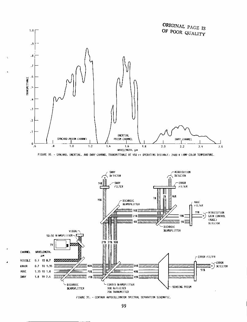
1 .o
. 9
.8
. 7
w .6 5 t
s
'2
2 . 5
I-
.4
.3
. 2
.1
0
I
- n U
ORIGINAL PAGE IS OF POOR QUALITY
ri'r2? SWAY CHANNEL
CHANNEL
V I S I BLE
ERROR
AQGC
SWAY
.6 .8 1.0 1.2 1 . 4 1.6 1.8 2 . 0 2.2 2.4 2.6 WAVELENGTH. pn
FIGURE 30. - SYNCHRO. INERTIAL. AND SWAY CHANNEL TRANSMITTANCE AT 450 FT OPERATING DISTANCE: 2400 K L W COLOR TEMPERATURE.
&ACQUISIT ION MTECTOR
BENISPLITTER
GAIN CONTROL
DETECTOR
BEAMSPLITTER
50:50 BEAMSPLITTER-\
Tv
WAVELENGTH,
ERROR FILTER 0.3 TO 0.7
0.7 TO 1.35
1.35 TO 1.8
1.8 TO 2.6
DICHROIC COATED E A M S P L I TTER BEAMSPLITTER 30% REFLECTED
70% TRANSMITTED
FIGURE 31, - CENTAUR AUTOCOLLIMATOR SPECTRAL SEPARATION SCHEMATIC.
99 I

1.2- --.1 REFERENCE
1.0 9 0 -
REFERENCE 1.0 - 1.0
1.or 1 0
REFERENCE A
- -0
.6 .8 1.0 1.5 2.0 2.5 3.0 WAVELENGTH, pM
FIGURE 32. - DICHROIC B E A M P L I T T E R .
1.2-
g .a t
g . 4
4' I-
.6 2 - 4
.2
.8
1 1 I 1 I I I I I I ' ' I I I ' 1 1 I $ 1.0 .6 .8 1.0 1.5 2.0 2.5 3.0
WAVELENGTH. PM
FIGURE 33. - VISUAL BEAMPLITTER: 90' INCIDENT ANGLE.
--.2 1.2- - -.2
8 .8-
t .6 -
L -
E - 5 -
- I- - - .4 5
- I L 2 W U - - .6 (L E .4-
.2 .8 - - .8
0 '
FIGURE 34. - SWAY CHANNEL F I L T E R : 90' I N C I E N T ANGLE.
1.0 0
1.2 -.2
1 .o v 0 REFERENCE REFERENCE
1.0 v -
.8 1.0 1.5 2.0
.2
WAVELENGTH. pH
FIGURE 36. - ACQUISIT ION BEAMSPLITTER. 45' I N C l D E N l ANGLE.
FIGURE 35. - SWAY CHANNEL BEAMSPLITTER: 45' I N C l D E N l ANGLE,
1.0
1 .? 2.5 '3.0 .6 .8 1.0 1.5 2.0
WAVELENGTH. pn FIGURE 37. - ERROR FILTER: 90' INCIDENT ANGLE.
100
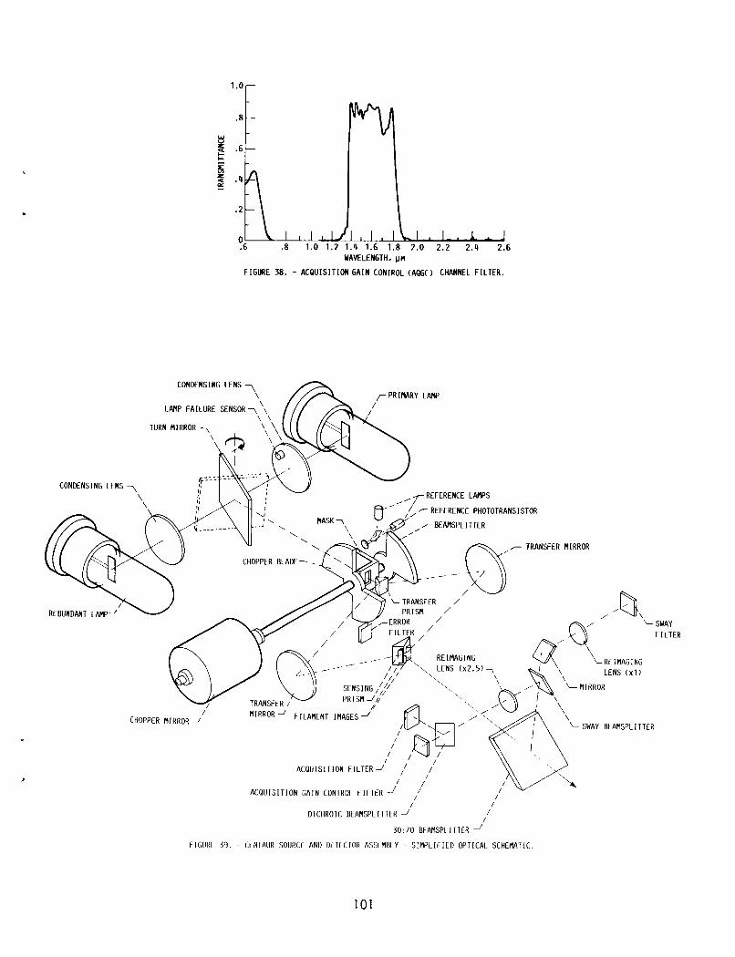
,
,
.6 .8 WAVELENGTH, ~n
FIGURE 38. - ACQUISIT ION G A I N CONTROL ( A Q G O CHANNEL F I L T E R .
\
TRANSFER MIRROR
RE IMAGING LENS ( ~ 2 . 5 ) ~
SENSING PRISMJk
I TRANSFER /
CHOPPER MIRROR -'
FIGURE 39. - (
'IRRoR J' FILAMENT IMAGES J' SWAY BEAMSPLITTER
ACQUISITION FILTER-'
I ACQUISIT ION GAIN CONTROL F I L T E R ' // /
/ / /
/ /
DICHROIC BEAMSPLITTER -' 30:70 BEAMSPLITTER
I N T A U R SOURCE AND DtTECTOR ASSEMBLY ~ S I M P L I F I E D OPTICAI. SCHEMATIC.
101

I ‘ I
ACQUISIT ION I PREAMPLIFIER ’h* GAiN W L I F IER PRISM ACQUISIT ION
I I I I I I
( 1
i i I I
REFERENCE SIGNAL GENERATOR i r
AMPLIFIER
102
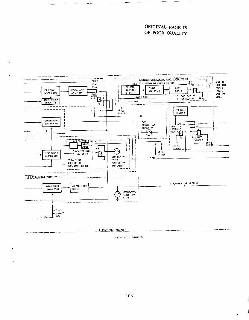
ORIGINAL PAGE IS OE POOR QUALITY
0
267 HZ REFERENCE
i l G U H t 43. - CONIINLCD.
103
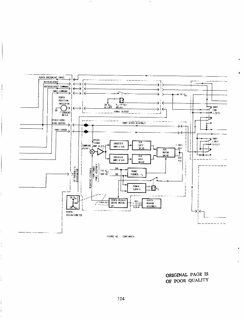
I
1
JTOCHECKOUT - \
C H E C K O ~ T C W N D '
PENTA POSIT ION
PETER
PENTA OVER-
I
I
' I I r'
I PENTA
i P o T E N T 1 ~ T E R
I
OPERA- TIONAL INVERTER GATE + OUT-
DR I VE MOTOR DRIVE
PUT GATE DRIVE
INVERTER W L I F I E R
FIGURE 40. ~ CONTINUED.
I I I I I I I I I I I I I I
I I i
I 1
(LEFT)
LIMIT (LEFT)
r-------- I I I I I I I I I I I I I "'I I I
ORIGINAL PAGE IS OF POOR QUALITY
104

L I M I T ( R I G H T )
LOGIC L I M I T SWITCHES
- - I-------- ~---------------- POWER PANEL ASSEMBCY I HAND CONTROL ASSENBLY I I
I I
I I I 28 V d c pRp " T $ i
PENTA
( R I G H T ) 1 I
I I
( L E F T ) ( R I G H T ) OVERRIDE
* I
105

runsn 1. Report No.
National AeronauIic~ and
2. Government Accession No. 3. Recipient's Catalog No.
Report Documentation Page
7. Author(s)
Andrew L. Gordan
8. Performing Organization Report No.
E-3226
NASA TM-88844 I I
9. Performing Organization Name and Address
National Aeronautics and Space Administration
I 5. Report Date 4. Title and Subtitle
91 7-60-00 11. Contract or Grant No.
Optical Alignment of Centaur's Inertial Guidance System
7. Key Words (Suggested by Author(s))
Optical theodol i te systems 18. Distribution Statement
Unclassified - Unlimited Subject Category 14
10. Work Unit No.
3. Security Classif. (of this report)
Unclassified 22. Price' 20. Security Classif. (of this page) 21. No of pages
Uncl ass i f i ed 106 A06
Lewis Research Center C1 eve1 and. Ohio 441 35-31 91 13. Type of Report and Period Covered
2. Sponsoring Agency Name and Address
National Aeronautics and Space Administration Washington, D.C. 20546-0001
5. Supplementary Notes
6. Abstract During Centaur launch operations the launch azimuth of the inertial platform's U-accelerometer input axis must be accurately established and maintained. This is accomplished by using an optically closed loop system with a long-range auto-theodolite whose line of sight has been established by a first-order survey. A collimated light beam from the autotheodolite intercepts a reflecting Porro prism mounted on the platform azimuth gimbal. Thus, any deviation of the Porro prism from its predetermined heading is optically detected by the autotheodolite. The error signal produced is used to torque the azimuth gimbal back to its required launch azimuth. The heading of the U-accelerometer input axis is there- fore maintained automatically. Previously, the autotheodolite system could not distinguish between vehicle sway (translatory motion) and rotational motion of the inertial platform unless at least three prisms were used. One prism was mounted on the inertial platform to maintain azimuth alignment, and two prisms were mounted externally on the vehicle to track sway. azimuth-laying theodolite (AALT-SV-M2> on the Saturn vehicle used three prisms. This report documents and describes the results of testing and modifying the AALT-SV-M2 autotheodolite to simultaneously monitor and maintain alignment of the inertial platform and track the sway of the vehicle from a single Porro Dri sm.
For example, the automatic