Embed Size (px)
DESCRIPTION
Optalign Plus Manual
Citation preview
OPTA
LIGN
PLUS O
perating Instructions 07.2002
i
EDITION July 2002ALI 9.560G, Firmware version 1.2x
Operating Instructionsand
Alignment Handbook
OPTALIGN® PLUS
Dear Customer,
If you have any suggestions for improvement or corrections (notonly to this manual, but also to software or hardware), please dropus a line! We would be glad to make improvements whereverpossible. We look forward to hearing from you!
PRÜFTECHNIK Alignment SystemsDocumentation DepartmentFax (+49) 89-99616-200eMail: [email protected]

OPT
ALI
GN
PLU
S O
pera
ting
Inst
ruct
ions
07.
2002
ii
Different markets, different OPTALIGNs
Please note that the components and functional capabilities of yourparticular instrument may vary from those described in this manual. Seeyour original price quotation and packing slip for definitive informationregarding your particular system, or ask your local PRÜFTECHNIKdealer for further details.
Depending upon the characteristics of your particular instrument, it maybe possible to upgrade to include the latest features. Contact your localPRÜFTECHNIK dealer for more information.
OPTA
LIGN
PLUS O
perating Instructions 07.2002
iii
Foreword
Foreword
Congratulations and thank you for your decision to entrust the shaftalignment of your machines to OPTALIGN PLUS! This all-new systemrepresents over a decade of experience by the pioneers in laser shaftalignment. Thanks to invaluable feedback received over the years fromlaser alignment customers such as yourself, all components ofOPTALIGN PLUS have been designed from the ground up to include thefeatures you want and need, such as:
� Enhanced measurement flexibility thanks to new measuring modes:- with minimum shaft rotation- with continuous shaft rotation- at freely selectable measurement positions� Elimination of coupling backlash effects� Graphic indication of compliance with alignment tolerances� Even easier keyboard operation� PC/printer interface� Auxiliary battery for back-up power supply� Extended battery life management� Non-volatile measurement storage� Job set-up, transfer and storage on PC
Of course, the new system also offers the complete range of features thathave made OPTALIGN the leading choice of shaft alignment expertsaround the world. Special situations like 6-feet machines, spacer shaftcouplings, vertical machines and thermal growth can all be handled withease. And the complete range of OPTALIGN accessories remains avail-able to adapt the new system to nearly any machine/coupling configura-tion you might encounter.
However, alignment needs do continue to change along with machinedesigns and operating practices, so please share your expertise with us!As in the past, your own experience will most assuredly play a decisiverole in the development of future alignment systems.
You can learn quite a great deal by simply taking the equipment out of itscase and working your way through this manual. To learn all thecapabilities of your new OPTALIGN PLUS and many of the finer points ofshaft alignment in general, contact your local PRÜFTECHNIK agent toregister for an in-depth alignment training course. If you are like mostalignment professionals, you will find it a few days well spent.
Once again, we would like to express our sincere appreciation for yourvote of confidence in OPTALIGN PLUS and for joining us in thecontinued commitment to alignment excellence.
July 2002PRÜFTECHNIK Alignment SystemsIsmaning, Germany

OPT
ALI
GN
PLU
S O
pera
ting
Inst
ruct
ions
07.
2002
iv
(Blank page)
1-1
OPTA
LIGN
PLUS O
perating Instructions 07.2002
Chapter 1: Introduction
This chapter includes general information regarding theOPTALIGN PLUS system and its operation including, in particular,the intended use and safety information.
Introduction
Chapter 1: Introduction .................................................. 1-1
The OPTALIGN PLUS package ............................................ 1-2Before you start... .............................................................. 1-4Safety and operating considerations .................................. 1-5Safety notes ...................................................................... 1-6
Laser safety .................................................................... 1-8Operating considerations ................................................... 1-9
Interface connections ................................................... 1-10Component labeling ..................................................... 1-11
Chapter 2 Description .........................................2-1 to 2-14
Chapter 3 Horizontal alignment ........................3-1 to 3-38
Chapter 4 Further functions ...............................4-1 to 4-36
Chapter 5 Vertical alignment .............................5-1 to 5-18
Chapter 6 Appendix ............................................6-1 to 6-50
1-2
OPT
ALI
GN
PLU
S O
pera
ting
Inst
ruct
ions
07.
2002
The OPTALIGN PLUS packageALI 5.000
ALI 5.000 EX
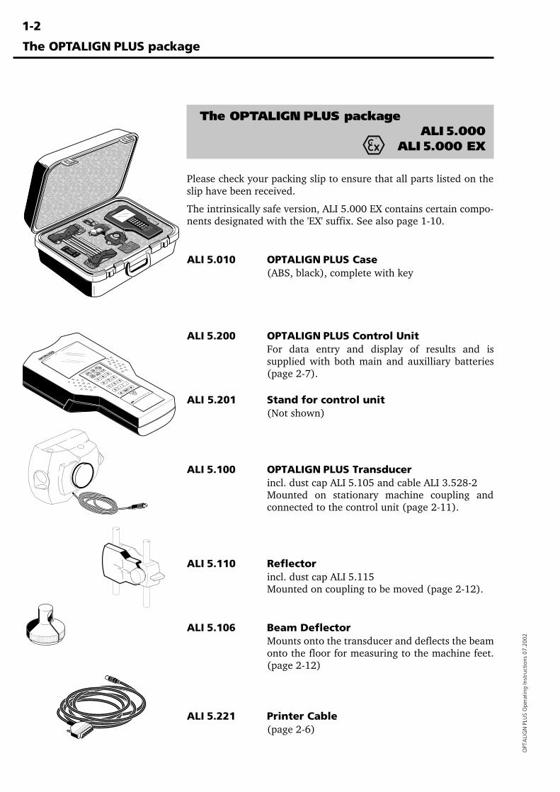
Please check your packing slip to ensure that all parts listed on theslip have been received.
The intrinsically safe version, ALI 5.000 EX contains certain compo-nents designated with the 'EX' suffix. See also page 1-10.
ALI 5.010 OPTALIGN PLUS Case(ABS, black), complete with key
ALI 5.200 OPTALIGN PLUS Control UnitFor data entry and display of results and issupplied with both main and auxilliary batteries(page 2-7).
ALI 5.201 Stand for control unit(Not shown)
ALI 5.100 OPTALIGN PLUS Transducerincl. dust cap ALI 5.105 and cable ALI 3.528-2Mounted on stationary machine coupling andconnected to the control unit (page 2-11).
ALI 5.110 Reflectorincl. dust cap ALI 5.115Mounted on coupling to be moved (page 2-12).
ALI 5.106 Beam DeflectorMounts onto the transducer and deflects the beamonto the floor for measuring to the machine feet.(page 2-12)
ALI 5.221 Printer Cable(page 2-6)
The OPTALIGN PLUS package
���������������������������������������������
������������������������������������������
����
���������������������������������������
���������
����
1-3
OPTA
LIGN
PLUS O
perating Instructions 07.2002
The OPTALIGN PLUS package
SHORT INSTRUCTIONS
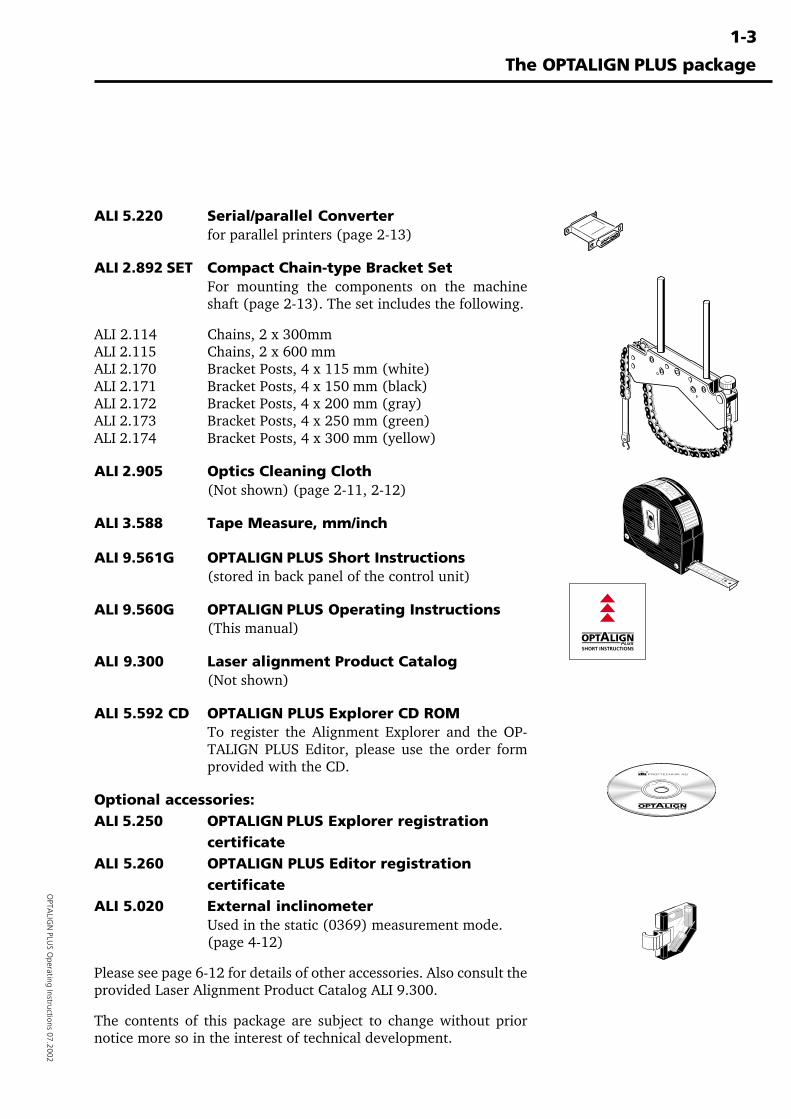
ALI 5.220 Serial/parallel Converterfor parallel printers (page 2-13)
ALI 2.892 SET Compact Chain-type Bracket SetFor mounting the components on the machineshaft (page 2-13). The set includes the following.
ALI 2.114 Chains, 2 x 300mmALI 2.115 Chains, 2 x 600 mmALI 2.170 Bracket Posts, 4 x 115 mm (white)ALI 2.171 Bracket Posts, 4 x 150 mm (black)ALI 2.172 Bracket Posts, 4 x 200 mm (gray)ALI 2.173 Bracket Posts, 4 x 250 mm (green)ALI 2.174 Bracket Posts, 4 x 300 mm (yellow)
ALI 2.905 Optics Cleaning Cloth(Not shown) (page 2-11, 2-12)
ALI 3.588 Tape Measure, mm/inch
ALI 9.561G OPTALIGN PLUS Short Instructions(stored in back panel of the control unit)
ALI 9.560G OPTALIGN PLUS Operating Instructions(This manual)
ALI 9.300 Laser alignment Product Catalog(Not shown)
ALI 5.592 CD OPTALIGN PLUS Explorer CD ROMTo register the Alignment Explorer and the OP-TALIGN PLUS Editor, please use the order formprovided with the CD.
Optional accessories:ALI 5.250 OPTALIGN PLUS Explorer registration
certificateALI 5.260 OPTALIGN PLUS Editor registration
certificateALI 5.020 External inclinometer
Used in the static (0369) measurement mode.(page 4-12)
Please see page 6-12 for details of other accessories. Also consult theprovided Laser Alignment Product Catalog ALI 9.300.
The contents of this package are subject to change without priornotice more so in the interest of technical development.
1-4
OPT
ALI
GN
PLU
S O
pera
ting
Inst
ruct
ions
07.
2002
Before you start...
Before you start...
Please take a moment to read through these important noticesbefore beginning alignment with OPTALIGN PLUS.
EveryonePlease acquaint yourself first with:��Safety and Operating Notes, on the following pages.��Warranty, Service and Care Information in chapter 6.��Batteries and memory on pages 2-7 to 2-10.
BeginnersHaving read the above notes, proceed with the following:��OPTALIGN PLUS Components in chapter 2.��What is Alignment? and relevant notes in chapter 6.��Then try an actual alignment starting page 3-6.
ExpertsEven if you have some experience in alignment, e.g. with OPTAL-IGN, please read the notes listed above for 'Everyone'.
You may then be able to start straight away by following the ShortInstructions on page 3-2. Step-by-step alignment for a standardhorizontal machine arrangement is described starting on page 3-6.After you have mastered a standard alignment, browse through thesections in chapter 4 to learn about OPTALIGN PLUS's specialcapabilities.
And finally,
Remember...
Ensure the machine cannot be accidentally started whiletaking measurements!
Remove all components from the shaft before switching themachine back on!
Do not stare into the laser beam!
WARNING!

1-5
OPTA
LIGN
PLUS O
perating Instructions 07.2002
Safety and operating considerations
Please read this section carefully!OPTALIGN PLUS system may give many users their first contactwith laser measurement technology. The following notes willacquaint you with several of the most important aspects of thesystem.
Safety and operating notes
CE complianceAll versions of OPTALIGN PLUS conform to all applicable CErequirements.
Intended useOPTALIGN PLUS may be used only for shaft alignment in industrialenvironments. The device must only be operated by properly trainedpersonnel. No liability may be assumed when components oroperating procedures as described in this manual are alteredwithout permission of the manufacturer.
Electromagnetic compatibility (EMC)All versions of OPTALIGN PLUS conform to the following EuropeanCommunity standards for electromagnetic compatibility: EN 55011Group 1, Class A and EN 50081-2.
Symbols used in this manualThe following symbols are used in this manual in order to draw thereader's attention to especially important text, such as that regard-ing possible sources of danger or useful operating tips.
This symbol denotes information which must be followed inorder to avoid personal injury.
This symbol denotes information which must be followed inorder to avoid damage to equipment.
This symbol denotes general information and tips regardingoperation of OPTALIGN PLUS. Note
�ATTENTION
WARNING!
1-6
OPT
ALI
GN
PLU
S O
pera
ting
Inst
ruct
ions
07.
2002
Safety and operating notes
Safety notes
GeneralPlease observe the following points in order to avoid personal injuryand damage to equipment:
� OPTALIGN PLUS must not be operated with the housing openor removed.
� OPTALIGN PLUS must be operated and maintained only bytrained personnel.
� Repairs may be performed only by factory-authorized servicepersonnel.
� Only original spare parts and accessories must be used.
� Any unauthorized modifications to OPTALIGN PLUS, its com-ponents and the operating procedures described herein shallrender all warranty coverage void.
� Ensure that the laser and sensor brackets fit solidly onto theirmounting surfaces!
� The specified system accuracy is applicable when the compo-nents are mounted with PRÜFTECHNIK-supplied brackets. Donot use self-constructed mounting brackets or modify the origi-nal bracket configuration.
� All components must be removed from the shafts or couplingbefore starting the machines! Otherwise, serious bodily injurymay result from flying parts.
WARNING!
ATTENTION
1-7
OPTA
LIGN
PLUS O
perating Instructions 07.2002
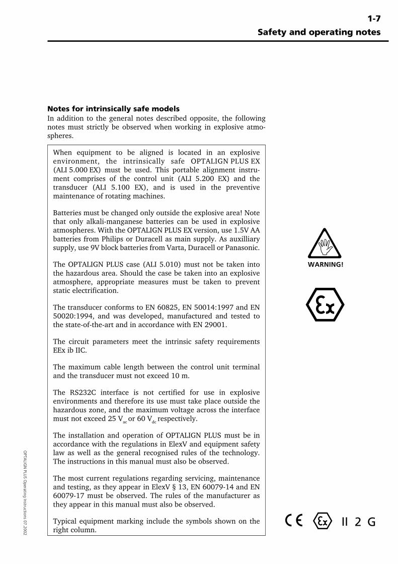
Notes for intrinsically safe modelsIn addition to the general notes described opposite, the followingnotes must strictly be observed when working in explosive atmo-spheres.
When equipment to be aligned is located in an explosiveenvironment, the intrinsically safe OPTALIGN PLUS EX(ALI 5.000 EX) must be used. This portable alignment instru-ment comprises of the control unit (ALI 5.200 EX) and thetransducer (ALI 5.100 EX), and is used in the preventivemaintenance of rotating machines.
Batteries must be changed only outside the explosive area! Notethat only alkali-manganese batteries can be used in explosiveatmospheres. With the OPTALIGN PLUS EX version, use 1.5V AAbatteries from Philips or Duracell as main supply. As auxilliarysupply, use 9V block batteries from Varta, Duracell or Panasonic.
The OPTALIGN PLUS case (ALI 5.010) must not be taken intothe hazardous area. Should the case be taken into an explosiveatmosphere, appropriate measures must be taken to preventstatic electrification.
The transducer conforms to EN 60825, EN 50014:1997 and EN50020:1994, and was developed, manufactured and tested tothe state-of-the-art and in accordance with EN 29001.
The circuit parameters meet the intrinsic safety requirementsEEx ib IIC.
The maximum cable length between the control unit terminaland the transducer must not exceed 10 m.
The RS232C interface is not certified for use in explosiveenvironments and therefore its use must take place outside thehazardous zone, and the maximum voltage across the interfacemust not exceed 25 Vac or 60 Vdc respectively.
The installation and operation of OPTALIGN PLUS must be inaccordance with the regulations in ElexV and equipment safetylaw as well as the general recognised rules of the technology.The instructions in this manual must also be observed.
The most current regulations regarding servicing, maintenanceand testing, as they appear in ElexV § 13, EN 60079-14 and EN60079-17 must be observed. The rules of the manufacturer asthey appear in this manual must also be observed.
Typical equipment marking include the symbols shown on theright column.
Safety and operating notes
WARNING!
II 2 G
1-8
OPT
ALI
GN
PLU
S O
pera
ting
Inst
ruct
ions
07.
2002
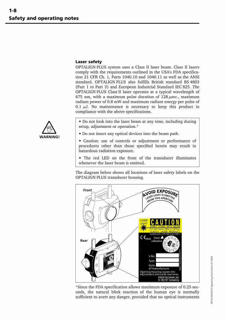
Laser safetyOPTALIGN PLUS system uses a Class II laser beam. Class II laserscomply with the requirements outlined in the USA's FDA specifica-tion 21 CFR Ch. 1, Parts 1040.10 and 1040.11 as well as the ANSIstandard. OPTALIGN PLUS also fulfills British standard BS 4803(Part 1 to Part 3) and European Industrial Standard IEC 825. TheOPTALIGN PLUS Class II laser operates at a typical wavelength of675 nm, with a maximum pulse duration of 128 µsec., maximumradiant power of 0.8 mW and maximum radiant energy per pulse of0.1 µJ. No maintenance is necessary to keep this product incompliance with the above specifications.
� Do not look into the laser beam at any time, including duringsetup, adjustment or operation.*
� Do not insert any optical devices into the beam path.
� Caution: use of controls or adjustment or performance ofprocedures other than those specified herein may result inhazardous radiation exposure.
� The red LED on the front of the transducer illuminateswhenever the laser beam is emitted.
The diagram below shows all locations of laser safety labels on theOPTALIGN PLUS transducer housing.
*Since the FDA specification allows maximum exposure of 0.25 sec-onds, the natural blink reaction of the human eye is normallysufficient to avert any danger, provided that no optical instruments
WARNING!
Front
Rear
Safety and operating notes

1-9
OPTA
LIGN
PLUS O
perating Instructions 07.2002
Safety and operating notes
�������������������������������
�������������������������������
Operating considerations
Temperature rangeThe OPTALIGN PLUS systemmay be used only at tempera-tures between 0° and 55° C (32°to 131° F). Outside of this range,the specified accuracy may notbe maintained. For further infor-mation regarding operating tem-perature, see page 6-45.
Store your OPTALIGN PLUSequipment at temperatures be-tween -20° C and 80° C (-4° F to176° F). Remember that on ahot day, the temperature inside alocked car can easily surpass80° C (176 °F)!
Sudden changes in temperature and humidity (for example, whenOPTALIGN PLUS is stored in an office but used in hot or cold workareas) can cause the optics to fog over with condensation: thecomputer displays "OFF" and stops measurement.
In that case, give the equipment about 10 minutes to reach thework area temperature.
Operating environment considerationsIf the transducer is subjected to strong, uneven heating duringmeasurement (such as when placed in direct sunlight), measure-ments may be affected by uneven expansion of the transducerhousing, which could cause the laser beam to deflect irregularly. Inthat case, allow several minutes for the OPTALIGN PLUS system toreach ambient temperature before beginning measurement; if indoubt, repeat the readings and compare them to establish repeat-ability.
Do not allow point light sources to shine directly into thetransducer; shade it if necessary during measurement.
Avoid exposing the OPTALIGN PLUS control unit directly tosources of thermal radiation such as direct sunlight.
The LCD display can act as a solar collector (at a rate of 10 watts!)and turn dark (reversibly) if overheated.
0° C32° F
55° C131° F
-20° C-4° F
80° C176° F
�Note
Note �
1-10
OPT
ALI
GN
PLU
S O
pera
ting
Inst
ruct
ions
07.
2002
Water and contamination resistanceThe OPTALIGN PLUS control unit is water and contaminationresistant to specification IP65; the transducer and prism are resis-tant to IP67. This specification requires that each component be ableto withstand a water jet spray from any direction (the componentsare NOT guaranteed to withstand a full submersion). Note: as withmost water-resistant products, the resistance must be periodicallychecked and re-sealed if necessary. This can be carried out duringOPTALIGN PLUS service and re-calibration which should be carriedout every two years.
Interface connectionsOPTALIGN PLUS uses the following interface connections:
1. The plug-in cable ALI 3.581-2 connects the transducer to thecontrol unit sensor socket. This cable normally remains attached tothe transducer; in case of damage, it may be replaced according tothe instructions given on page 6-29 of this manual.
2. The plug-in printer cable ALI 5.221 connects the 6-pin RS232socket of the control unit to the serial/parallel converter ALI 5.220which in turn connects to the PC end of the parallel (Centronics)printer cable (see page 2-6).
Note regarding data storage
With any data processing software, data may be lost or alteredunder certain circumstances. PRÜFTECHNIK strongly recom-mends that you keep separate written or printed records of allimportant data.
PRÜFTECHNIK assumes no responsibility for data lost or alteredas a result of improper use, repairs, defects, battery replace-ment/failures or any other cause.
PRÜFTECHNIK assumes no responsibility, directly or indirectly,for financial losses or claims from third parties resulting fromthe use of this product and any of its functions, such as loss oralteration of stored data, etc.
Safety and operating notes
�Note
1-11
OPTA
LIGN
PLUS O
perating Instructions 07.2002
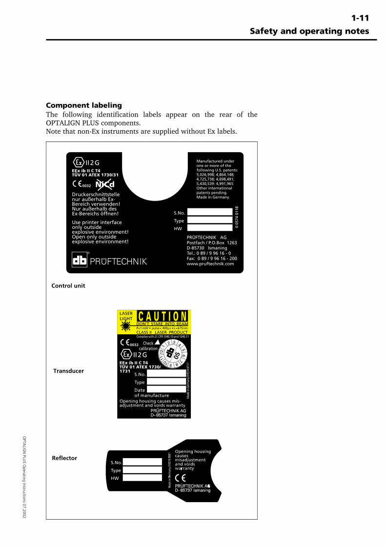
Component labelingThe following identification labels appear on the rear of theOPTALIGN PLUS components.Note that non-Ex instruments are supplied without Ex labels.
Transducer
Reflector
Control unit
Safety and operating notes

1-1
2
OPTALIGN PLUS Operating Instructions 07.2002
Blank page
2-1
OPTA
LIGN
PLUS O
perating Instructions 07.2002
Chapter 2: Description
This chapter includes a description of OPTALIGN PLUS and itscomponents.
Chapter 1 Introduction ...................................... 1-1 to 1-12
Chapter 3 Horizontal alignment ....................... 3-1 to 3-38
Chapter 4 Further functions .............................. 4-1 to 4-36
Chapter 5 Vertical alignment ............................ 5-1 to 5-18
Chapter 6 Appendix ........................................... 6-1 to 6-50
Chapter 2: Description
Chapter 2: Description ....................................................2-1
OPTALIGN PLUS overview .................................................2-2OPTALIGN PLUS components ............................................2-3The OPTALIGN PLUS Control unit .....................................2-3
The OPTALIGN PLUS keyboard at a glance .....................2-4The OPTALIGN PLUS screen ...........................................2-5The OPTALIGN PLUS control unit (top view) .................2-6Transducer connection & RS232/printer interface .........2-6
Batteries ............................................................................2-7Transducer ALI 5.100......................................................2-11Reflector ALI 5.110 .........................................................2-12Compact chain-type bracket ALI 2.892 SET ....................2-13Beam deflector ALI 5.106 ..............................................2-13Serial/parallel converter ALI 5.220 .................................2-14Accessories .......................................................................2-14
2-2
OPT
ALI
GN
PLU
S O
pera
ting
Inst
ruct
ions
07.
2002
OPTALIGN PLUS overview
OPTALIGN PLUS overview
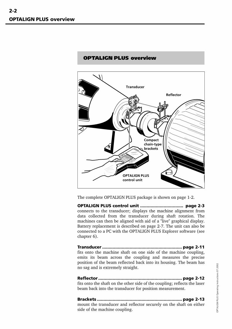
The complete OPTALIGN PLUS package is shown on page 1-2.
OPTALIGN PLUS control unit ................................. page 2-3connects to the transducer; displays the machine alignment fromdata collected from the transducer during shaft rotation. Themachines can then be aligned with aid of a "live" graphical display.Battery replacement is described on page 2-7. The unit can also beconnected to a PC with the OPTALIGN PLUS Explorer software (seechapter 6).
Transducer ............................................................. page 2-11fits onto the machine shaft on one side of the machine coupling,emits its beam across the coupling and measures the preciseposition of the beam reflected back into its housing. The beam hasno sag and is extremely straight.
Reflector ................................................................ page 2-12fits onto the shaft on the other side of the coupling; reflects the laserbeam back into the transducer for position measurement.
Brackets ................................................................. page 2-13mount the transducer and reflector securely on the shaft on eitherside of the machine coupling.
OPTALIGN PLUScontrol unit
Compactchain-typebrackets
Reflector
Transducer
2-3
OPTA
LIGN
PLUS O
perating Instructions 07.2002
OPTALIGN PLUS components
Descriptions of the main OPTALIGN PLUS components are given onthe following pages.
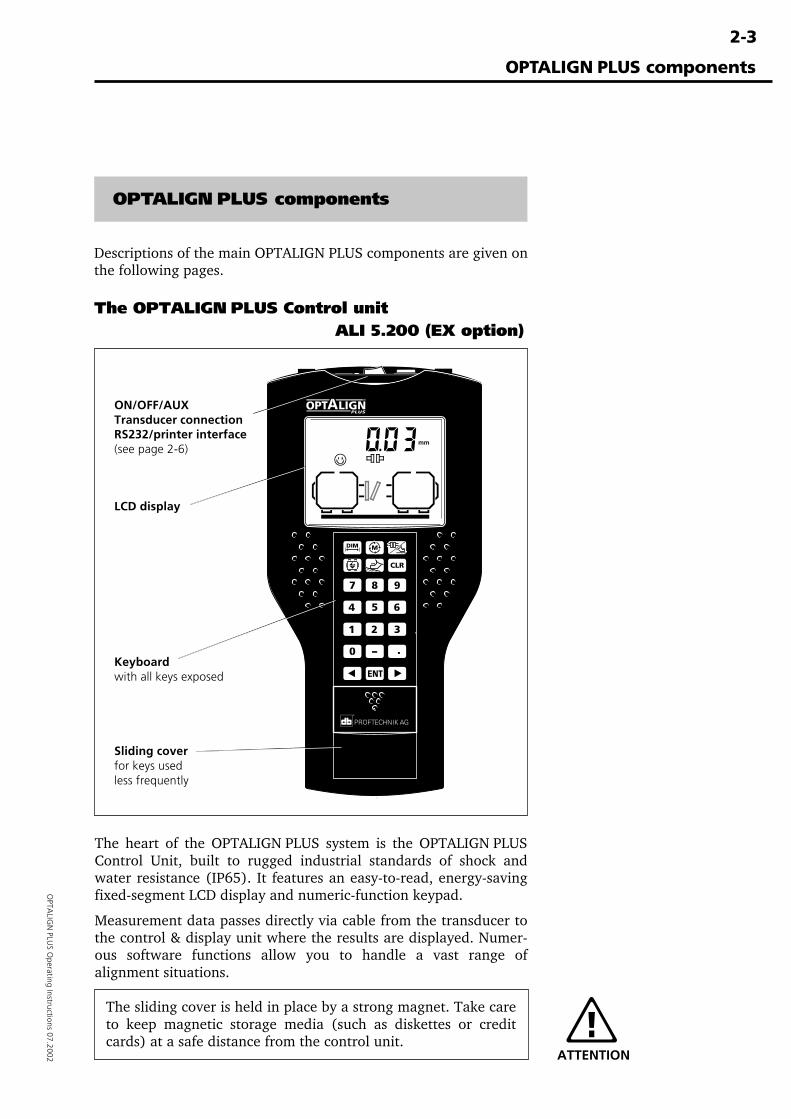
The OPTALIGN PLUS Control unitALI 5.200 (EX option)
The heart of the OPTALIGN PLUS system is the OPTALIGN PLUSControl Unit, built to rugged industrial standards of shock andwater resistance (IP65). It features an easy-to-read, energy-savingfixed-segment LCD display and numeric-function keypad.
Measurement data passes directly via cable from the transducer tothe control & display unit where the results are displayed. Numer-ous software functions allow you to handle a vast range ofalignment situations.
The sliding cover is held in place by a strong magnet. Take careto keep magnetic storage media (such as diskettes or creditcards) at a safe distance from the control unit.
OPTALIGN PLUS components
Keyboardwith all keys exposed
ON/OFF/AUXTransducer connectionRS232/printer interface(see page 2-6)
LCD display
Sliding coverfor keys usedless frequently
ATTENTION
2-4
OPT
ALI
GN
PLU
S O
pera
ting
Inst
ruct
ions
07.
2002
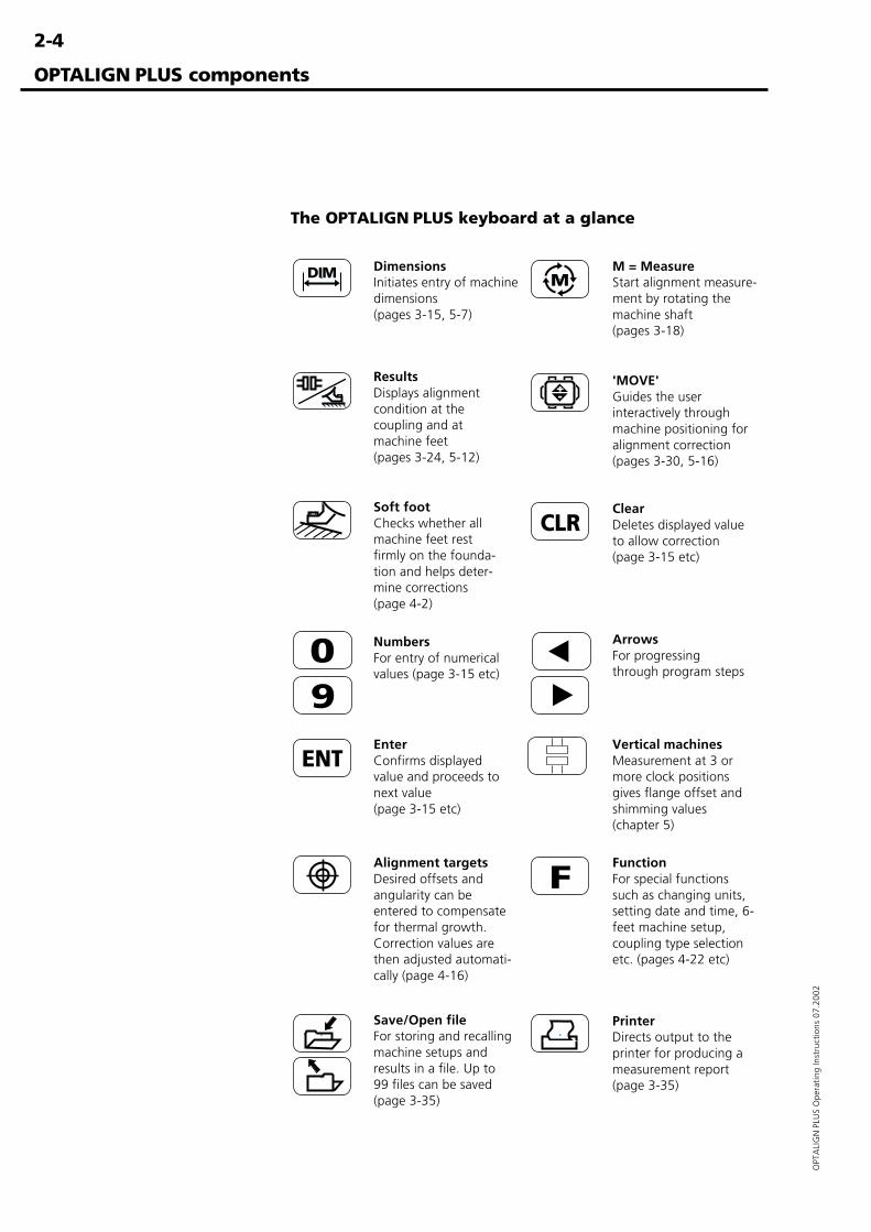
The OPTALIGN PLUS keyboard at a glance
ResultsDisplays alignmentcondition at thecoupling and atmachine feet(pages 3-24, 5-12)
M = MeasureStart alignment measure-ment by rotating themachine shaft(pages 3-18)
Alignment targetsDesired offsets andangularity can beentered to compensatefor thermal growth.Correction values arethen adjusted automati-cally (page 4-16)
EnterConfirms displayedvalue and proceeds tonext value(page 3-15 etc)
Soft footChecks whether allmachine feet restfirmly on the founda-tion and helps deter-mine corrections(page 4-2)
FunctionFor special functionssuch as changing units,setting date and time, 6-feet machine setup,coupling type selectionetc. (pages 4-22 etc)
PrinterDirects output to theprinter for producing ameasurement report(page 3-35)
ArrowsFor progressingthrough program steps
ClearDeletes displayed valueto allow correction(page 3-15 etc)
DimensionsInitiates entry of machinedimensions(pages 3-15, 5-7)
'MOVE'Guides the userinteractively throughmachine positioning foralignment correction(pages 3-30, 5-16)
NumbersFor entry of numericalvalues (page 3-15 etc)
Save/Open fileFor storing and recallingmachine setups andresults in a file. Up to99 files can be saved(page 3-35)
OPTALIGN PLUS components
Vertical machinesMeasurement at 3 ormore clock positionsgives flange offset andshimming values(chapter 5)
2-5
OPTA
LIGN
PLUS O
perating Instructions 07.2002
The OPTALIGN PLUS screen
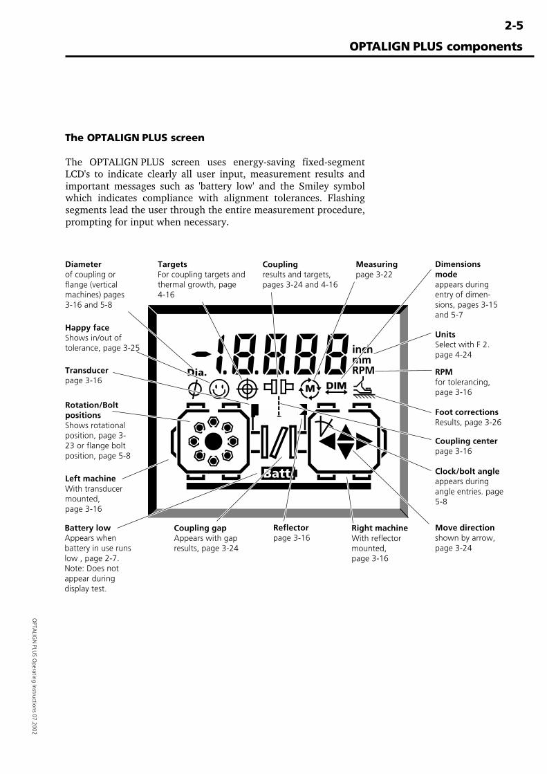
The OPTALIGN PLUS screen uses energy-saving fixed-segmentLCD's to indicate clearly all user input, measurement results andimportant messages such as 'battery low' and the Smiley symbolwhich indicates compliance with alignment tolerances. Flashingsegments lead the user through the entire measurement procedure,prompting for input when necessary.
OPTALIGN PLUS components
UnitsSelect with F 2.page 4-24
Battery lowAppears whenbattery in use runslow , page 2-7.Note: Does notappear duringdisplay test.
Happy faceShows in/out oftolerance, page 3-25
Diameterof coupling orflange (verticalmachines) pages3-16 and 5-8
Dimensionsmodeappears duringentry of dimen-sions, pages 3-15and 5-7
RPMfor tolerancing,page 3-16
Foot correctionsResults, page 3-26
Rotation/BoltpositionsShows rotationalposition, page 3-23 or flange boltposition, page 5-8
TargetsFor coupling targets andthermal growth, page4-16
Couplingresults and targets,pages 3-24 and 4-16
Measuringpage 3-22
Left machineWith transducermounted,page 3-16
Transducerpage 3-16
Coupling gapAppears with gapresults, page 3-24
Reflectorpage 3-16
Right machineWith reflectormounted,page 3-16
Clock/bolt angleappears duringangle entries. page5-8
Move directionshown by arrow,page 3-24
Coupling centerpage 3-16
2-6
OPT
ALI
GN
PLU
S O
pera
ting
Inst
ruct
ions
07.
2002
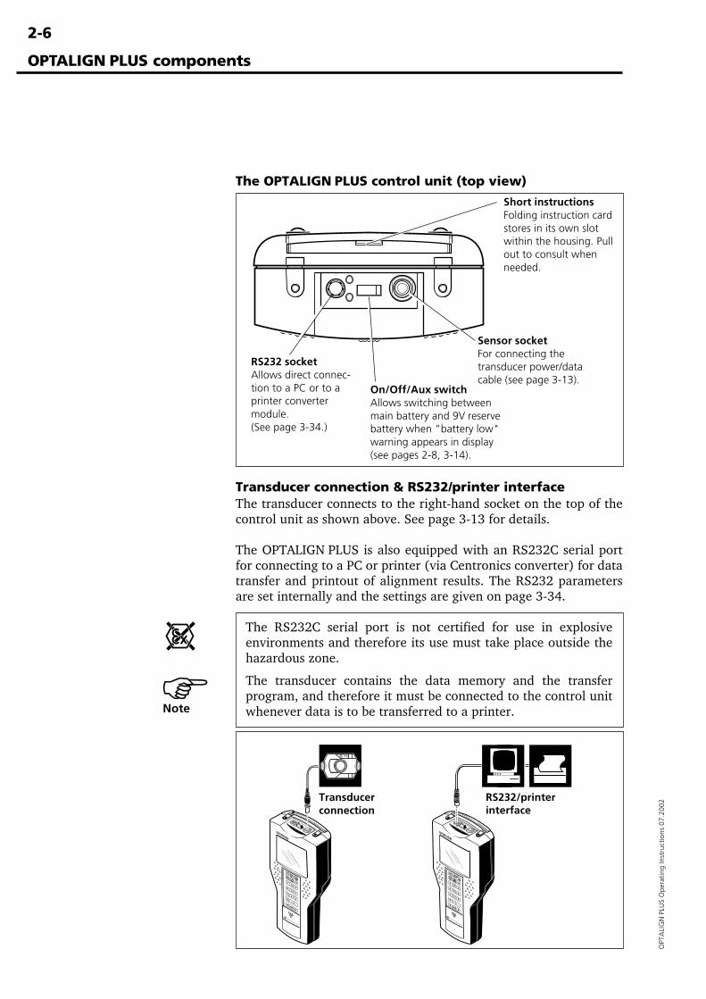
Transducer connection & RS232/printer interfaceThe transducer connects to the right-hand socket on the top of thecontrol unit as shown above. See page 3-13 for details.
The OPTALIGN PLUS is also equipped with an RS232C serial portfor connecting to a PC or printer (via Centronics converter) for datatransfer and printout of alignment results. The RS232 parametersare set internally and the settings are given on page 3-34.
The RS232C serial port is not certified for use in explosiveenvironments and therefore its use must take place outside thehazardous zone.
The transducer contains the data memory and the transferprogram, and therefore it must be connected to the control unitwhenever data is to be transferred to a printer.
The OPTALIGN PLUS control unit (top view)
OPTALIGN PLUS components
Sensor socketFor connecting thetransducer power/datacable (see page 3-13).
On/Off/Aux switchAllows switching betweenmain battery and 9V reservebattery when "battery low"warning appears in display(see pages 2-8, 3-14).
Short instructionsFolding instruction cardstores in its own slotwithin the housing. Pullout to consult whenneeded.
RS232 socketAllows direct connec-tion to a PC or to aprinter convertermodule.(See page 3-34.)
ONOFF
AUX
ONOFF
AUX
Transducerconnection
RS232/printerinterface
�Note
2-7
OPTA
LIGN
PLUS O
perating Instructions 07.2002
Batteries
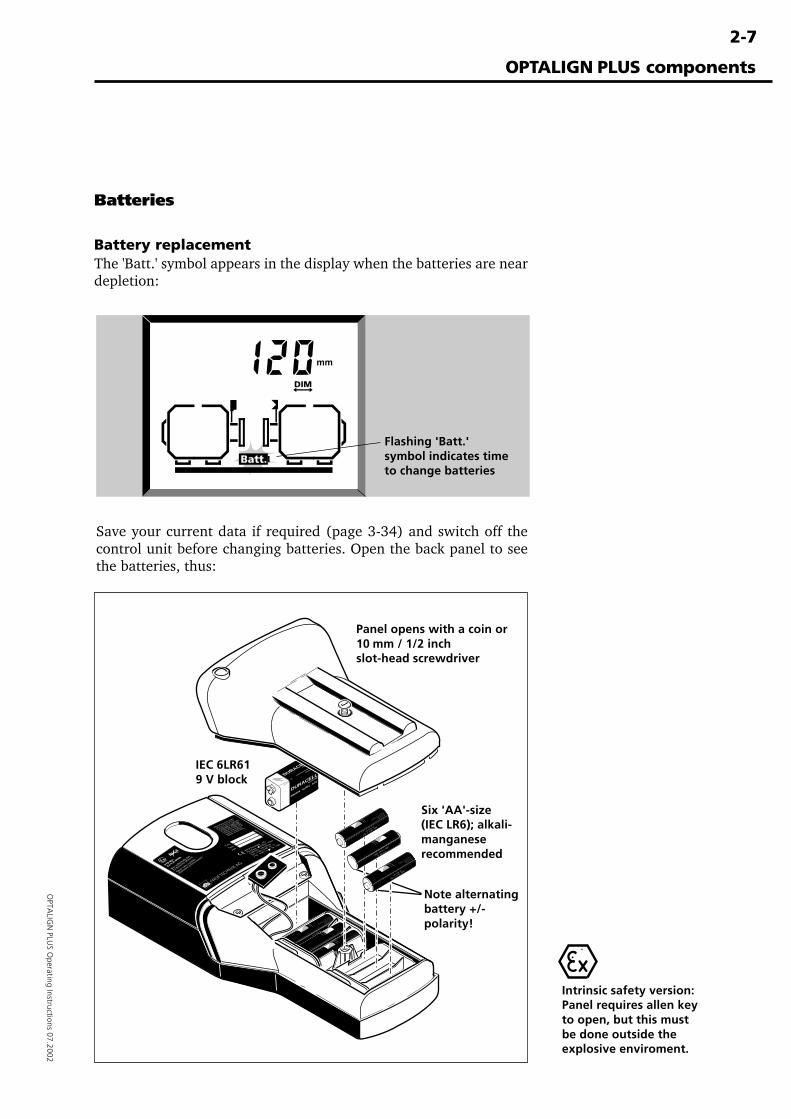
Battery replacementThe 'Batt.' symbol appears in the display when the batteries are neardepletion:
Save your current data if required (page 3-34) and switch off thecontrol unit before changing batteries. Open the back panel to seethe batteries, thus:
OPTALIGN PLUS components
Intrinsic safety version:Panel requires allen keyto open, but this mustbe done outside theexplosive enviroment.
Six 'AA'-size(IEC LR6); alkali-manganeserecommended
Panel opens with a coin or10 mm / 1/2 inchslot-head screwdriver
IEC 6LR619 V block
Flashing 'Batt.'symbol indicates timeto change batteries
Note alternatingbattery +/-polarity!
Baby LR 14 C AM2
No 4014 1,5 V
Nicht ins Feuer werfen!
Nicht wiederaufladbar.
May explode in fire! Not rechargeable.
Ne pas jeter au feu! non rechargeable.
Baby LR 14 C AM2
No 4014 1,5 V
Baby LR 14 C AM2
No 4014 1,5 V
Nicht ins Feuer werfen!
Nicht wiederaufladbar.
May explode in fire! Not rechargeable.
Ne pas jeter au feu! non rechargeable.
Baby LR 14 C AM2
No 4014 1,5 V
Nicht ins Feuer werfen!
Nicht wiederaufladbar.
May explode in fire! Not rechargeable.
Ne pas jeter au feu! non rechargeable.
DURACELLALKALINE
DURACELLALKALIN
E
MN1604 6LR61 9
,0V
Baby LR 14 C AM2
No 4014 1,5 V
Nicht ins Feuer werfen!
Nicht wiederaufladbar.
May explode in fire! Not rechargeable.
Ne pas jeter au feu! non rechargeable.
Baby LR 14 C AM2
No 4014 1,5 V
2-8
OPT
ALI
GN
PLU
S O
pera
ting
Inst
ruct
ions
07.
2002
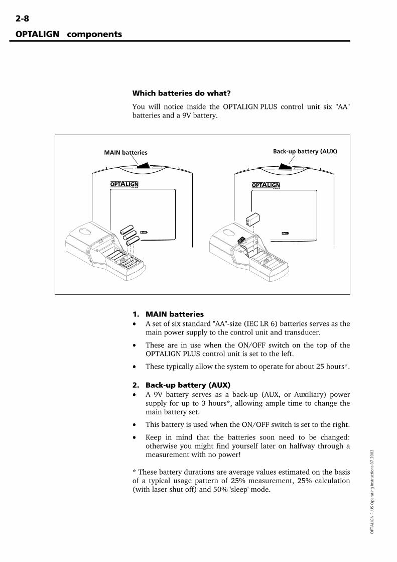
Which batteries do what?
You will notice inside the OPTALIGN PLUS control unit six "AA"batteries and a 9V battery.
MAIN batteries Back-up battery (AUX)
1. MAIN batteries· A set of six standard "AA"-size (IEC LR 6) batteries serves as the
main power supply to the control unit and transducer.
· These are in use when the ON/OFF switch on the top of theOPTALIGN PLUS control unit is set to the left.
· These typically allow the system to operate for about 25 hours*.
2. Back-up battery (AUX)· A 9V battery serves as a back-up (AUX, or Auxiliary) power
supply for up to 3 hours*, allowing ample time to change themain battery set.
· This battery is used when the ON/OFF switch is set to the right.
· Keep in mind that the batteries soon need to be changed:otherwise you might find yourself later on halfway through ameasurement with no power!
* These battery durations are average values estimated on the basisof a typical usage pattern of 25% measurement, 25% calculation(with laser shut off) and 50% 'sleep' mode.
OPTALIGN components
2-9
OPTA
LIGN
PLUS O
perating Instructions 07.2002
Which batteries do I replace?When 'Batt.' blinks you know that the battery or batteries currentlybeing used are depleted. Remove batteries as soon as they becomedepleted or if the system is not to be used for an extended period toavoid any unpleasant consequences of battery leakage. Beforeswitching off, switch over to the other battery or batteries to see ifthey are dead too, then you can replace them at the same time.
Any type of good-quality batteries can be used with the standardOPTALIGN PLUS, including alkali-manganese or metal hydridecells.
Used batteries should be disposed of in an environmentally respon-sible manner in accordance with applicable regulations!
Batteries for intrinsically safe versionThe intrinsically safe version of OPTALIGN PLUS, ALI 5.000 EX(with all electrical components also suffixed by "EX"), requiresspecial attention with regard to batteries.
Only alkali-manganese batteries of the makes listed below maybe used with the intrinsically safe version:9V: Varta, Duracell or Panasonic1.5V: Philips or DuracellOtherwise, intrinsic safety may be compromised.
Be sure to remove the control unit from the explosive environ-ment before changing batteries.
DO NOT USE lithium batteries or nickel-cadmium rechargeablebatteries in explosive environments.
Main or Back-up (Reserve)?
1. The control unit is normally operated with the MAIN batteries(6 x AA cells), when the ON/OFF switch is set to the left.
2. When these batteries become depleted, the 'Batt.' symbolflashes, indicating that they should be replaced very soon.
3. If you can't or don't want to change the main batteries right inthe middle of an important job, you can set the ON/OFF switchto the right to the reserve battery. When the reserve batterybecomes depleted, the 'Batt.' symbol reappears.
'Resume' functionOPTALIGN PLUS stores all dimensions, measurements andsettings in a non-volatile memory which is continuously updat-ed. If the batteries become depleted or the unit is switched offfor more than about 2 seconds (e.g. when switching from Mainto Reserve), the system will reset itself and all dimensions etcwill be cleared. Even then, though, you can resume where youleft off by switching on and loading file '0'. See chapter 3 fordetails.
OPTALIGN PLUS components
�Note
WARNING!
2-10
OPT
ALI
GN
PLU
S O
pera
ting
Inst
ruct
ions
07.
2002
Electronic memory
The OPTALIGN PLUS system contains a non-volatile electronicmemory for long-term storage of measurements and results, evenwhen the unit is switched off. The most recent data set isautomatically stored in a special file named '0' and may be laterrecalled, immediately after switching on.
� In common with all electronic memory products of this nature,data can be lost or altered under certain circumstances.
� Please keep a record of important data. PRÜFTECHNIK AGassumes no responsibility for data lost or altered.
� The OPTALIGN PLUS Explorer software program can be usedto back-up data to a PC. See chapter 6 for details.
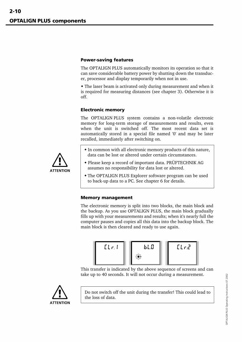
Memory management
The electronic memory is split into two blocks, the main block andthe backup. As you use OPTALIGN PLUS, the main block graduallyfills up with your measurements and results; when it's nearly full thecomputer pauses and copies all this data into the backup block. Themain block is then cleared and ready to use again.
This transfer is indicated by the above sequence of screens and cantake up to 40 seconds. It will not occur during a measurement.
OPTALIGN PLUS components
Power-saving features
The OPTALIGN PLUS automatically monitors its operation so that itcan save considerable battery power by shutting down the transduc-er, processor and display temporarily when not in use.
� The laser beam is activated only during measurement and when itis required for measuring distances (see chapter 3). Otherwise it isoff.
ATTENTION
Do not switch off the unit during the transfer! This could lead tothe loss of data.
ATTENTION
2-11
OPTA
LIGN
PLUS O
perating Instructions 07.2002
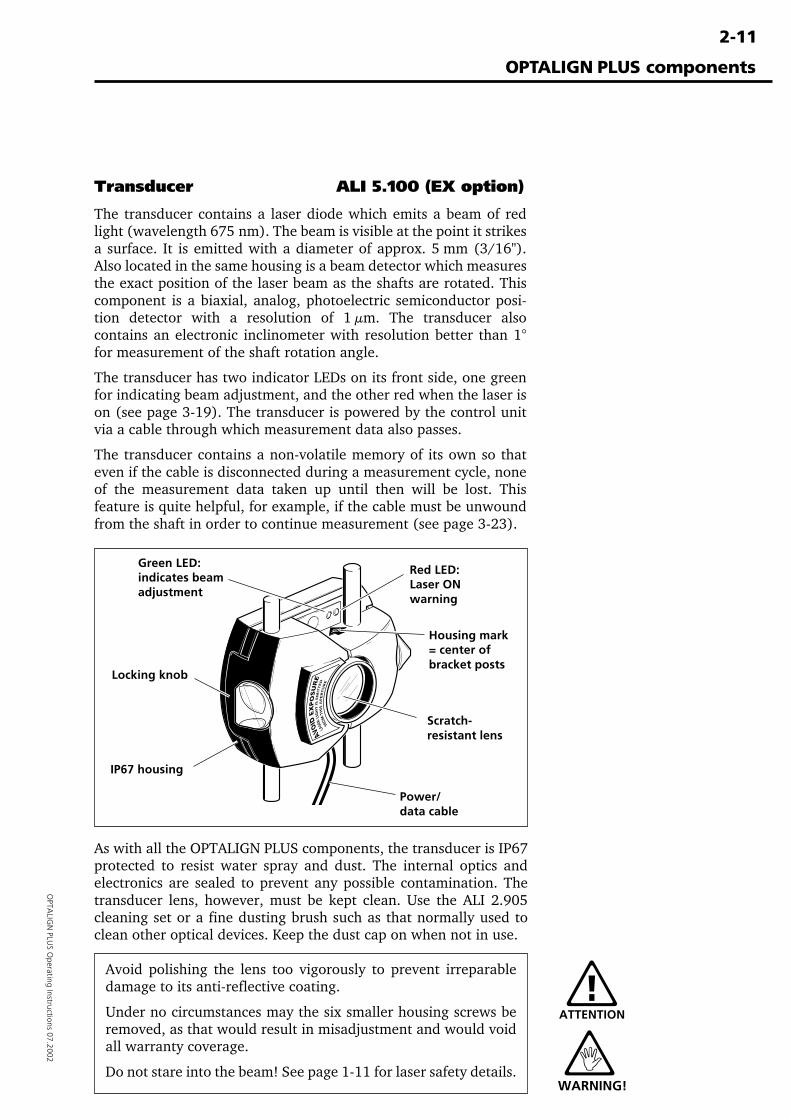
Transducer ALI 5.100 (EX option)
The transducer contains a laser diode which emits a beam of redlight (wavelength 675 nm). The beam is visible at the point it strikesa surface. It is emitted with a diameter of approx. 5 mm (3/16").Also located in the same housing is a beam detector which measuresthe exact position of the laser beam as the shafts are rotated. Thiscomponent is a biaxial, analog, photoelectric semiconductor posi-tion detector with a resolution of 1 µm. The transducer alsocontains an electronic inclinometer with resolution better than 1°for measurement of the shaft rotation angle.
The transducer has two indicator LEDs on its front side, one greenfor indicating beam adjustment, and the other red when the laser ison (see page 3-19). The transducer is powered by the control unitvia a cable through which measurement data also passes.
The transducer contains a non-volatile memory of its own so thateven if the cable is disconnected during a measurement cycle, noneof the measurement data taken up until then will be lost. Thisfeature is quite helpful, for example, if the cable must be unwoundfrom the shaft in order to continue measurement (see page 3-23).
As with all the OPTALIGN PLUS components, the transducer is IP67protected to resist water spray and dust. The internal optics andelectronics are sealed to prevent any possible contamination. Thetransducer lens, however, must be kept clean. Use the ALI 2.905cleaning set or a fine dusting brush such as that normally used toclean other optical devices. Keep the dust cap on when not in use.
Avoid polishing the lens too vigorously to prevent irreparabledamage to its anti-reflective coating.
Under no circumstances may the six smaller housing screws beremoved, as that would result in misadjustment and would voidall warranty coverage.
Do not stare into the beam! See page 1-11 for laser safety details.
ATTENTION
OPTALIGN PLUS components
Locking knob
Green LED:indicates beamadjustment
IP67 housing
Scratch-resistant lens
Power/data cable
Red LED:Laser ONwarning
Housing mark= center ofbracket posts
WARNING!
2-12
OPT
ALI
GN
PLU
S O
pera
ting
Inst
ruct
ions
07.
2002
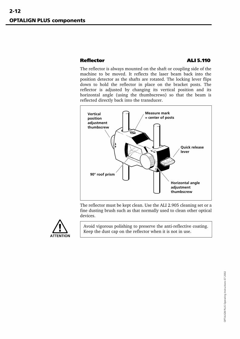
Reflector ALI 5.110
The reflector is always mounted on the shaft or coupling side of themachine to be moved. It reflects the laser beam back into theposition detector as the shafts are rotated. The locking lever flipsdown to hold the reflector in place on the bracket posts. Thereflector is adjusted by changing its vertical position and itshorizontal angle (using the thumbscrews) so that the beam isreflected directly back into the transducer.
The reflector must be kept clean. Use the ALI 2.905 cleaning set or afine dusting brush such as that normally used to clean other opticaldevices.
Avoid vigorous polishing to preserve the anti-reflective coating.Keep the dust cap on the reflector when it is not in use.
OPTALIGN PLUS components
Quick releaselever
90° roof prism
Horizontal angleadjustmentthumbscrew
Verticalpositionadjustmentthumbscrew
Measure mark= center of posts
ATTENTION
2-13
OPTA
LIGN
PLUS O
perating Instructions 07.2002
OPTALIGN PLUS components
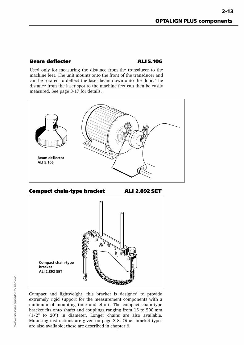
Beam deflector ALI 5.106
Used only for measuring the distance from the transducer to themachine feet. The unit mounts onto the front of the transducer andcan be rotated to deflect the laser beam down onto the floor. Thedistance from the laser spot to the machine feet can then be easilymeasured. See page 3-17 for details.
Beam deflectorALI 5.106
Compact and lightweight, this bracket is designed to provideextremely rigid support for the measurement components with aminimum of mounting time and effort. The compact chain-typebracket fits onto shafts and couplings ranging from 15 to 500 mm(1/2" to 20") in diameter. Longer chains are also available.Mounting instructions are given on page 3-8. Other bracket typesare also available; these are described in chapter 6.
Compact chain-type bracket ALI 2.892 SET
Compact chain-typebracketALI 2.892 SET
2-14
OPT
ALI
GN
PLU
S O
pera
ting
Inst
ruct
ions
07.
2002
OPTALIGN PLUS components
Accessories
Among the most useful accessories are the various brackets speciallydesigned for mounting OPTALIGN PLUS on specific machine config-urations. These are described in detail in the appendix to thismanual (chapter 6).
The 'Product Catalog for Laser Alignment Systems' illustrates anddescribes the additional accessories available for OPTALIGN PLUS.It is available under order number ALI 9.300.
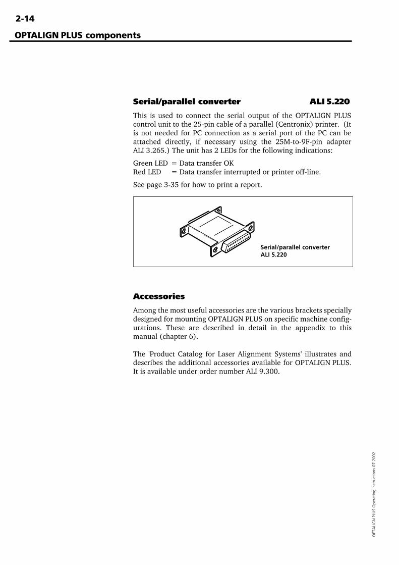
Serial/parallel converter ALI 5.220
This is used to connect the serial output of the OPTALIGN PLUScontrol unit to the 25-pin cable of a parallel (Centronix) printer. (Itis not needed for PC connection as a serial port of the PC can beattached directly, if necessary using the 25M-to-9F-pin adapterALI 3.265.) The unit has 2 LEDs for the following indications:
Green LED = Data transfer OKRed LED = Data transfer interrupted or printer off-line.
See page 3-35 for how to print a report.
Serial/parallel converterALI 5.220

3-1
OPTA
LIGN
PLUS O
perating Instructions 07.2002
Chapter 3: Horizontal machine alignment
This chapter includes detailed instructions on basic alignment ofhorizontal machine sets.
Chapter 1 Introduction .......................................1-1 to 1-12
Chapter 2 Description .........................................2-1 to 2-14
Chapter 3: Horizontal machine alignment ................... 3-1Short instructions ........................................................................ 3-2Horizontal machine alignment flow chart ................................... 3-4Horizontal machine alignment .................................................... 3-6
1. Preparing for the alignment procedure ................................ 3-72. Mount the brackets .............................................................. 3-83. Mount the transducer and reflector ................................... 3-104. Connect the transducer ...................................................... 3-135. Switch on the control unit ................................................. 3-146. Machine dimensions .......................................................... 3-15
Enter the dimensions ......................................................... 3-157. Laser beam adjustment ...................................................... 3-188. Take measurements ........................................................... 3-229. Results ............................................................................... 3-24
a. Misalignment at coupling ............................................... 3-24b. Foot corrections.............................................................. 3-26
10. Align machine .................................................................. 3-28Vertical Shimming .............................................................. 3-28Horizontal and vertical alignment using MOVE ................. 3-30
11. Alignment completion ..................................................... 3-3412. Saving data and printing.................................................. 3-3513. Hot alignment check ........................................................ 3-36
Chapter 4 Further functions ...............................4-1 to 4-36
Chapter 5 Vertical alignment .............................5-1 to 5-18
Chapter 6 Appendix ............................................6-1 to 6-50
Horizontal machine alignment
3-2
OPT
ALI
GN
PLU
S O
pera
ting
Inst
ruct
ions
07.
2002
Horizontal machine alignment : Short instructions
Short instructions
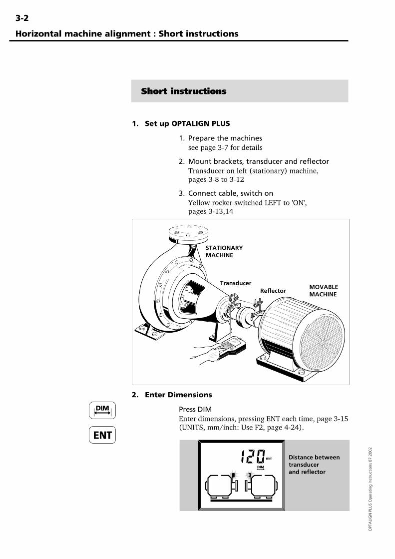
1. Set up OPTALIGN PLUS
1. Prepare the machinessee page 3-7 for details
2. Mount brackets, transducer and reflectorTransducer on left (stationary) machine,pages 3-8 to 3-12
3. Connect cable, switch onYellow rocker switched LEFT to 'ON',pages 3-13,14
2. Enter Dimensions
Press DIMEnter dimensions, pressing ENT each time, page 3-15(UNITS, mm/inch: Use F2, page 4-24).
STATIONARYMACHINE
MOVABLEMACHINE
TransducerReflector
Distance betweentransducerand reflector
3-3
OPTA
LIGN
PLUS O
perating Instructions 07.2002
Horizontal machine alignment : Short instructions
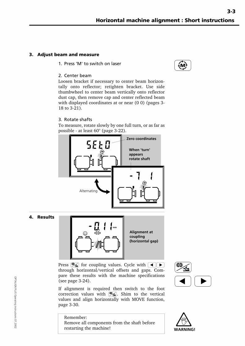
3. Adjust beam and measure
1. Press 'M' to switch on laser
2. Center beamLoosen bracket if necessary to center beam horizon-tally onto reflector; retighten bracket. Use sidethumbwheel to center beam vertically onto reflectordust cap, then remove cap and center reflected beamwith displayed coordinates at or near (0 0) (pages 3-18 to 3-21).
3. Rotate shaftsTo measure, rotate slowly by one full turn, or as far aspossible - at least 60° (page 3-22).
4. Results
Press for coupling values. Cycle with through horizontal/vertical offsets and gaps. Com-pare these results with the machine specifications(see page 3-24).
If alignment is required then switch to the footcorrection values with . Shim to the verticalvalues and align horizontally with MOVE function,page 3-30.
Remember:Remove all components from the shaft beforerestarting the machine!
Alternating
WARNING!
When 'turn'appearsrotate shaft
Zero coordinates
Alignment atcoupling(horizontal gap)
3-4
OPT
ALI
GN
PLU
S O
pera
ting
Inst
ruct
ions
07.
2002
Horizontal machine alignment : flow chart
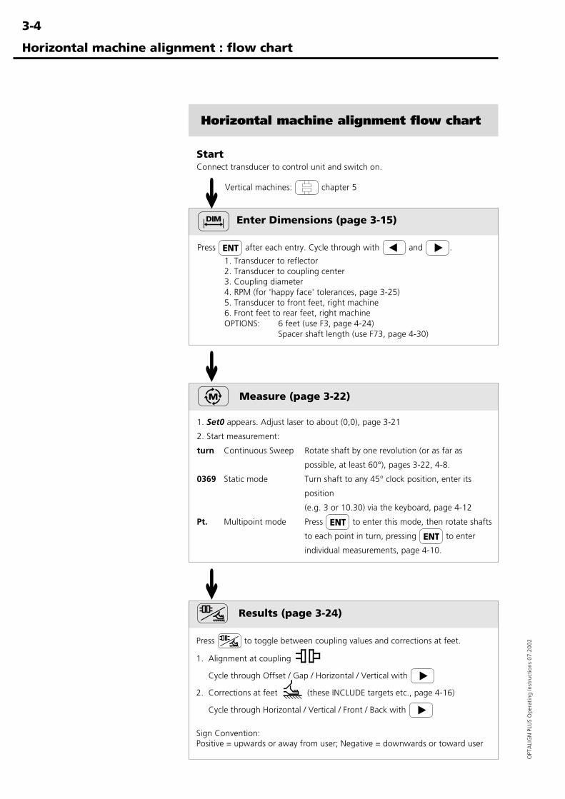
Horizontal machine alignment flow chart
StartConnect transducer to control unit and switch on.
Enter Dimensions (page 3-15)
Press after each entry. Cycle through with and .
1. Transducer to reflector2. Transducer to coupling center3. Coupling diameter4. RPM (for 'happy face' tolerances, page 3-25)5. Transducer to front feet, right machine6. Front feet to rear feet, right machineOPTIONS: 6 feet (use F3, page 4-24)
Spacer shaft length (use F73, page 4-30)
Measure (page 3-22)
1. Set0 appears. Adjust laser to about (0,0), page 3-21
2. Start measurement:
turn Continuous Sweep Rotate shaft by one revolution (or as far as
possible, at least 60°), pages 3-22, 4-8.
0369 Static mode Turn shaft to any 45° clock position, enter its
position
(e.g. 3 or 10.30) via the keyboard, page 4-12
Pt. Multipoint mode Press to enter this mode, then rotate shafts
to each point in turn, pressing to enter
individual measurements, page 4-10.
Results (page 3-24)
Press to toggle between coupling values and corrections at feet.
1. Alignment at coupling
Cycle through Offset / Gap / Horizontal / Vertical with
2. Corrections at feet (these INCLUDE targets etc., page 4-16)
Cycle through Horizontal / Vertical / Front / Back with
Sign Convention:Positive = upwards or away from user; Negative = downwards or toward user
Vertical machines: chapter 5
➜➜
➜
3-5
OPTA
LIGN
PLUS O
perating Instructions 07.2002
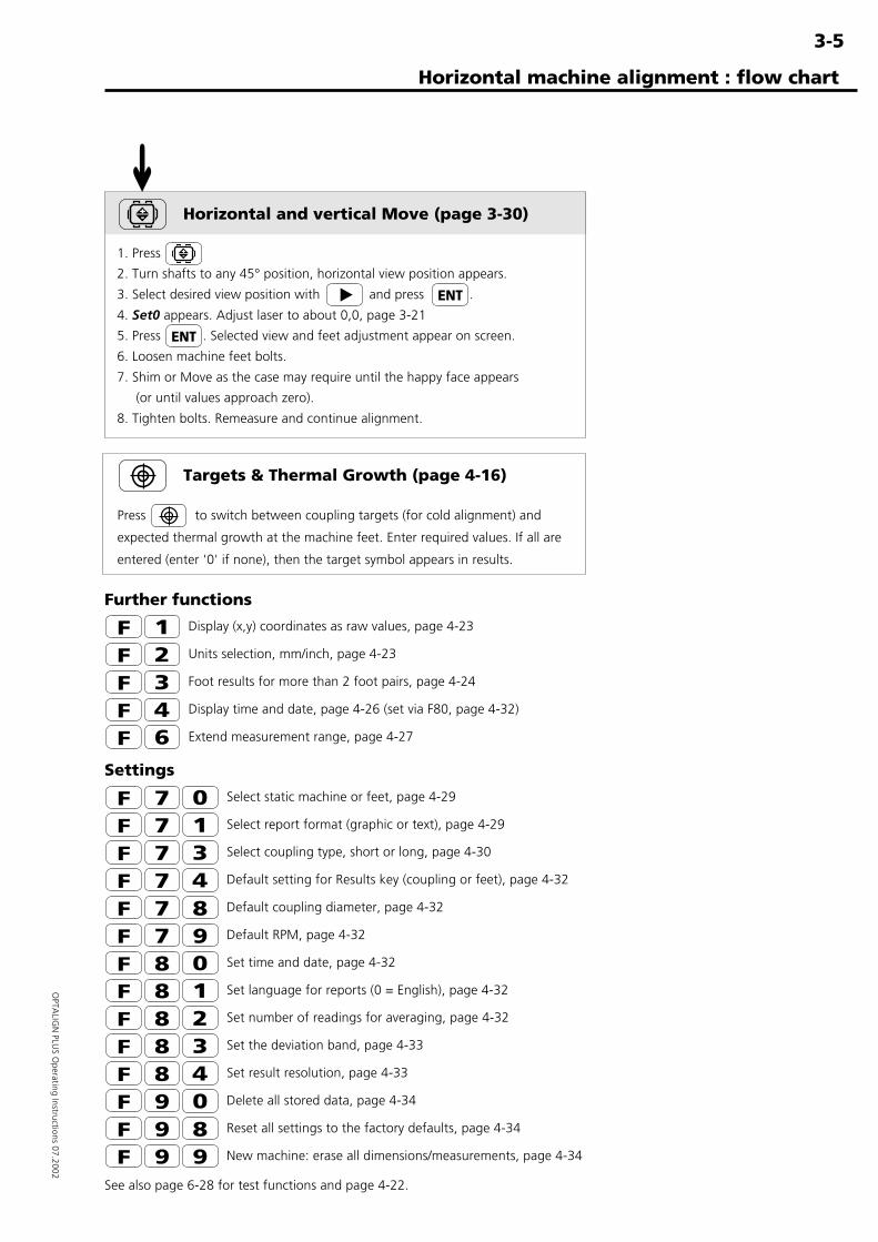
Further functions
Display (x,y) coordinates as raw values, page 4-23
Units selection, mm/inch, page 4-23
Foot results for more than 2 foot pairs, page 4-24
Display time and date, page 4-26 (set via F80, page 4-32)
Extend measurement range, page 4-27
Settings
Select static machine or feet, page 4-29
Select report format (graphic or text), page 4-29
Select coupling type, short or long, page 4-30
Default setting for Results key (coupling or feet), page 4-32
Default coupling diameter, page 4-32
Default RPM, page 4-32
Set time and date, page 4-32
Set language for reports (0 = English), page 4-32
Set number of readings for averaging, page 4-32
Set the deviation band, page 4-33
Set result resolution, page 4-33
Delete all stored data, page 4-34
Reset all settings to the factory defaults, page 4-34
New machine: erase all dimensions/measurements, page 4-34
See also page 6-28 for test functions and page 4-22.
Horizontal and vertical Move (page 3-30)
1. Press
2. Turn shafts to any 45° position, horizontal view position appears.
3. Select desired view position with and press .
4. Set0 appears. Adjust laser to about 0,0, page 3-21
5. Press . Selected view and feet adjustment appear on screen.
6. Loosen machine feet bolts.
7. Shim or Move as the case may require until the happy face appears
(or until values approach zero).
8. Tighten bolts. Remeasure and continue alignment.
Horizontal machine alignment : flow chart
➜
Targets & Thermal Growth (page 4-16)
Press to switch between coupling targets (for cold alignment) and
expected thermal growth at the machine feet. Enter required values. If all are
entered (enter '0' if none), then the target symbol appears in results.
3-6
OPT
ALI
GN
PLU
S O
pera
ting
Inst
ruct
ions
07.
2002
Horizontal machine alignment
Horizontal machine alignment
The OPTALIGN PLUS program covers practically any alignmentsituation. A multitude of options are available using the 'F' functionkeys described later on. For most applications though, the "straightthrough" approach should apply where the default settings areperfectly suitable and the special options are not required.
For clarity, only the "straight through" method is described in detailhere. The options are mentioned briefly and page references as towhere they are described within the manual are provided. The flowchart on the previous page gives a complete overview.
As this is the main instruction procedure, it is important to acquaintyourself with this chapter before moving to vertical machines orspecial cases.
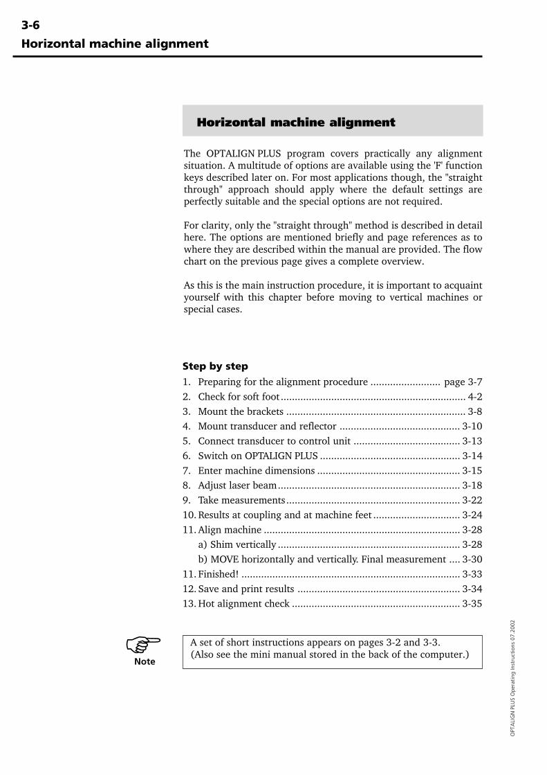
Step by step
1. Preparing for the alignment procedure ......................... page 3-72. Check for soft foot .................................................................. 4-23. Mount the brackets ................................................................ 3-84. Mount transducer and reflector ........................................... 3-105. Connect transducer to control unit ...................................... 3-136. Switch on OPTALIGN PLUS .................................................. 3-147. Enter machine dimensions ................................................... 3-158. Adjust laser beam................................................................. 3-189. Take measurements.............................................................. 3-2210. Results at coupling and at machine feet ............................... 3-2411. Align machine ...................................................................... 3-28
a) Shim vertically ................................................................. 3-28b) MOVE horizontally and vertically. Final measurement .... 3-30
11. Finished! .............................................................................. 3-3312. Save and print results .......................................................... 3-3413. Hot alignment check ............................................................ 3-35
A set of short instructions appears on pages 3-2 and 3-3.(Also see the mini manual stored in the back of the computer.)�Note
3-7
OPTA
LIGN
PLUS O
perating Instructions 07.2002
Horizontal machine alignment
1. Preparing for the alignment procedure
Before using OPTALIGN PLUS, make sure the machine is properlyprepared for alignment as described below. See page 6-6 for furtherinformation.
Switch off the machines before commencing work, and make surethat they cannot be started accidentally!
a. Solid, flat foundation
b. Machine mobilityStart with about 2 mm (80 mils) of shims beneath each foot.Hydraulic or screw-type positioning aids are recommended forhorizontal movement.
c. Rigid couplingsRigid couplings must be loosened before measurement so that theydo not distort the alignment condition.
d. Shaft play and coupling backlashThe OPTALIGN PLUS raw coordinate display function can measureradial play when the shafts are lifted. Axial shaft play—up to 3 mm(1/8")—can be tolerated during measurement (although not neces-sarily for machine operation!). Up to 5° of coupling backlash can betolerated during measurement. By turning the shaft on the reflectorside, even larger degrees of play will have no effect on measuringaccuracy.
e. Soft footSoft foot causes the machine to tip into a different position everytime the bolts are loosened, making proper alignment difficult orimpossible. This can be checked with OPTALIGN PLUS immediatelybefore measuring alignment (pages 3-21 and 4-2).
f. Thermal growth, alignment targets, tolerancesFind out from specifications what these values are for your ma-chines. They can then be entered into the program (page 4-16).
g. Measurement separationSince the OPTALIGN PLUS system requires no mechanical connec-tions (such as cantilevered dial indicator brackets) to span over thecoupling during measurement, alignment may easily be performedover large transducer–reflector separations. Longer separations arepossible using "Extend" function, pages 4-27.
Note that over very large distances the shafts and coupling may sag,and the machines may need to be aligned to take this into account.Refer to the machine manufacturer's specifications.
WARNING!
3-8
OPT
ALI
GN
PLU
S O
pera
ting
Inst
ruct
ions
07.
2002
Horizontal machine alignment
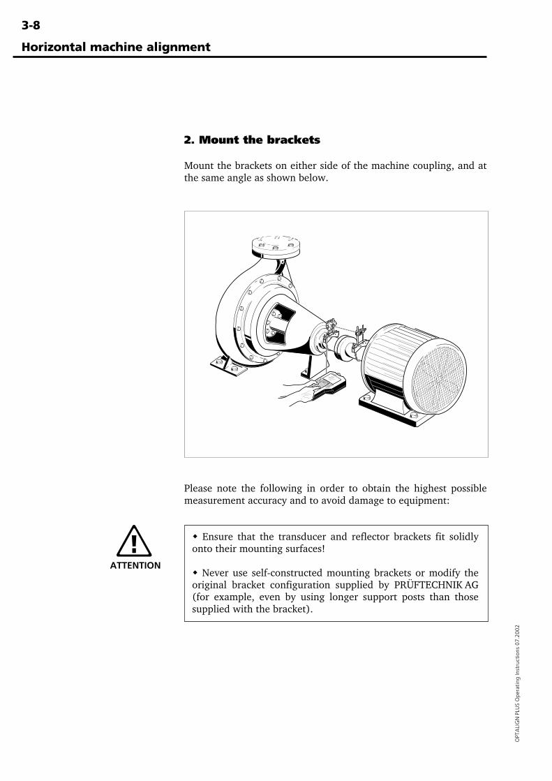
2. Mount the brackets
Mount the brackets on either side of the machine coupling, and atthe same angle as shown below.
Please note the following in order to obtain the highest possiblemeasurement accuracy and to avoid damage to equipment:
� Ensure that the transducer and reflector brackets fit solidlyonto their mounting surfaces!
� Never use self-constructed mounting brackets or modify theoriginal bracket configuration supplied by PRÜFTECHNIK AG(for example, even by using longer support posts than thosesupplied with the bracket).
ATTENTION
3-9
OPTA
LIGN
PLUS O
perating Instructions 07.2002
Horizontal machine alignment
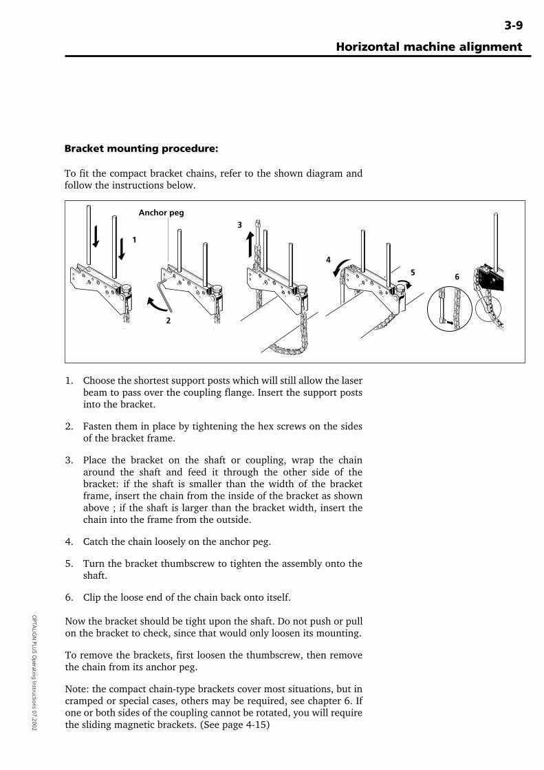
Bracket mounting procedure:
To fit the compact bracket chains, refer to the shown diagram andfollow the instructions below.
1. Choose the shortest support posts which will still allow the laserbeam to pass over the coupling flange. Insert the support postsinto the bracket.
2. Fasten them in place by tightening the hex screws on the sidesof the bracket frame.
3. Place the bracket on the shaft or coupling, wrap the chainaround the shaft and feed it through the other side of thebracket: if the shaft is smaller than the width of the bracketframe, insert the chain from the inside of the bracket as shownabove ; if the shaft is larger than the bracket width, insert thechain into the frame from the outside.
4. Catch the chain loosely on the anchor peg.
5. Turn the bracket thumbscrew to tighten the assembly onto theshaft.
6. Clip the loose end of the chain back onto itself.
Now the bracket should be tight upon the shaft. Do not push or pullon the bracket to check, since that would only loosen its mounting.
To remove the brackets, first loosen the thumbscrew, then removethe chain from its anchor peg.
Note: the compact chain-type brackets cover most situations, but incramped or special cases, others may be required, see chapter 6. Ifone or both sides of the coupling cannot be rotated, you will requirethe sliding magnetic brackets. (See page 4-15)
1
2
3
4
5 6
Anchor peg
3-10
OPT
ALI
GN
PLU
S O
pera
ting
Inst
ruct
ions
07.
2002
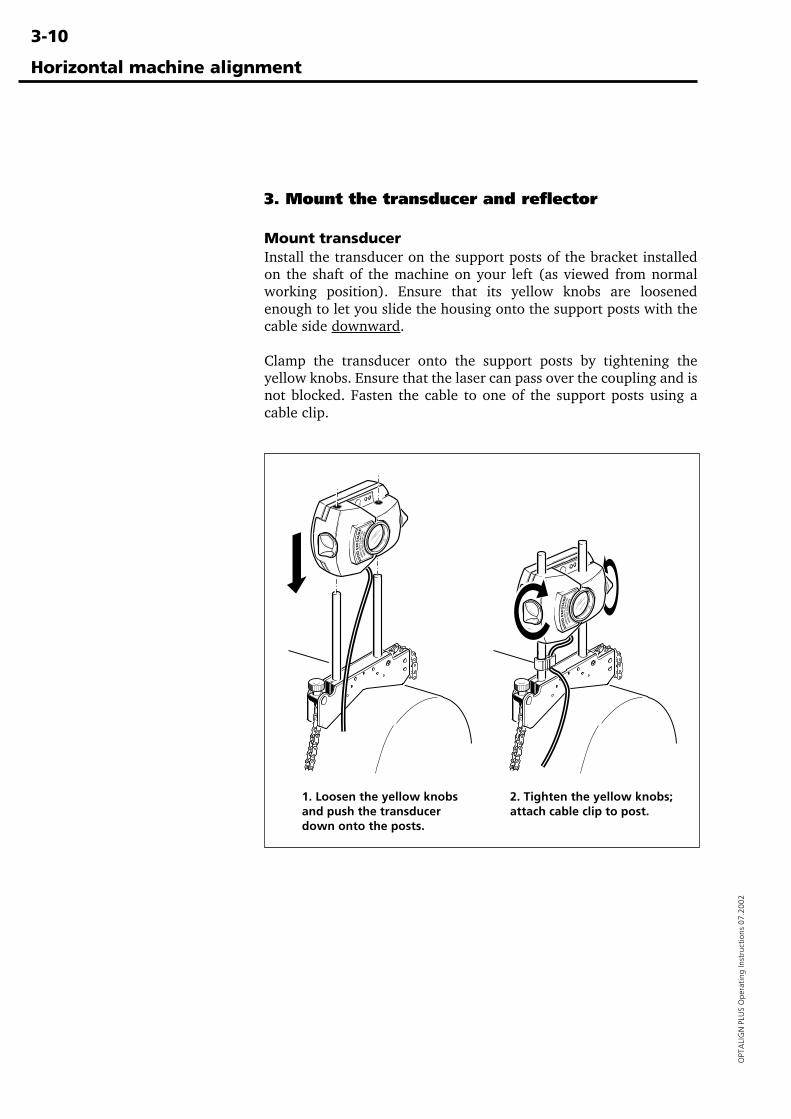
3. Mount the transducer and reflector
Mount transducerInstall the transducer on the support posts of the bracket installedon the shaft of the machine on your left (as viewed from normalworking position). Ensure that its yellow knobs are loosenedenough to let you slide the housing onto the support posts with thecable side downward.
Clamp the transducer onto the support posts by tightening theyellow knobs. Ensure that the laser can pass over the coupling and isnot blocked. Fasten the cable to one of the support posts using acable clip.
Horizontal machine alignment
1. Loosen the yellow knobsand push the transducerdown onto the posts.
2. Tighten the yellow knobs;attach cable clip to post.
3-11
OPTA
LIGN
PLUS O
perating Instructions 07.2002
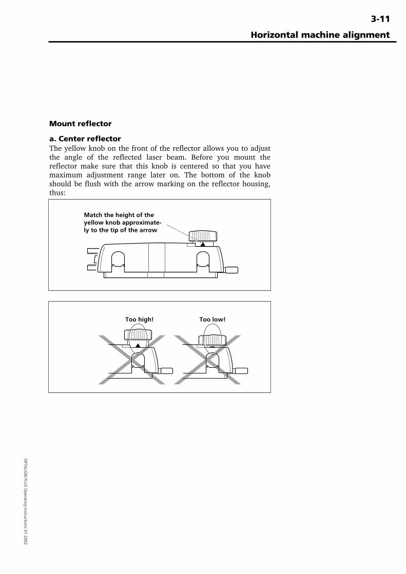
Match the height of theyellow knob approximate-ly to the tip of the arrow
Too high! Too low!
Mount reflector
a. Center reflectorThe yellow knob on the front of the reflector allows you to adjustthe angle of the reflected laser beam. Before you mount thereflector make sure that this knob is centered so that you havemaximum adjustment range later on. The bottom of the knobshould be flush with the arrow marking on the reflector housing,thus:
Horizontal machine alignment
3-12
OPT
ALI
GN
PLU
S O
pera
ting
Inst
ruct
ions
07.
2002
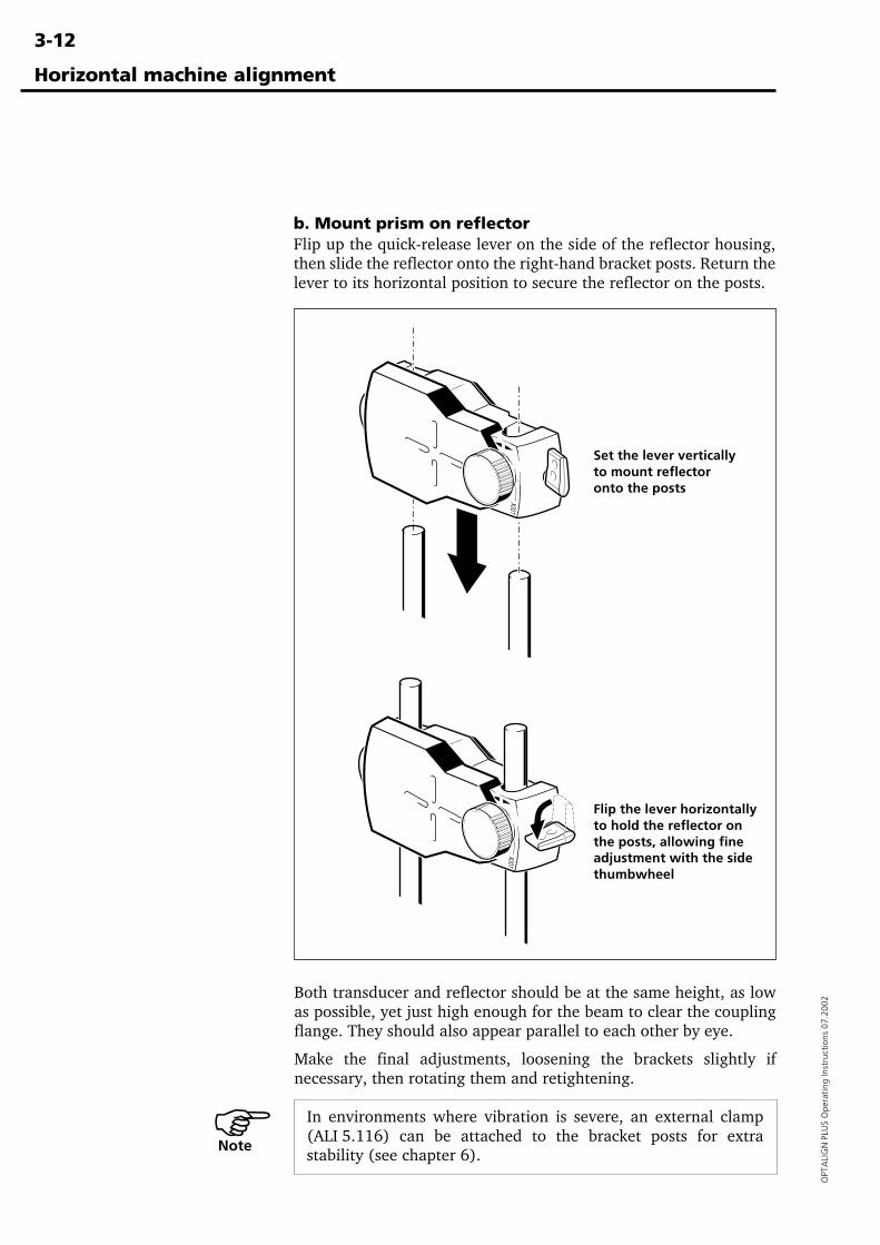
Horizontal machine alignment
b. Mount prism on reflectorFlip up the quick-release lever on the side of the reflector housing,then slide the reflector onto the right-hand bracket posts. Return thelever to its horizontal position to secure the reflector on the posts.
Both transducer and reflector should be at the same height, as lowas possible, yet just high enough for the beam to clear the couplingflange. They should also appear parallel to each other by eye.
Make the final adjustments, loosening the brackets slightly ifnecessary, then rotating them and retightening.
In environments where vibration is severe, an external clamp(ALI 5.116) can be attached to the bracket posts for extrastability (see chapter 6).
Flip the lever horizontallyto hold the reflector onthe posts, allowing fineadjustment with the sidethumbwheel
Set the lever verticallyto mount reflectoronto the posts
Note �
3-13
OPTA
LIGN
PLUS O
perating Instructions 07.2002
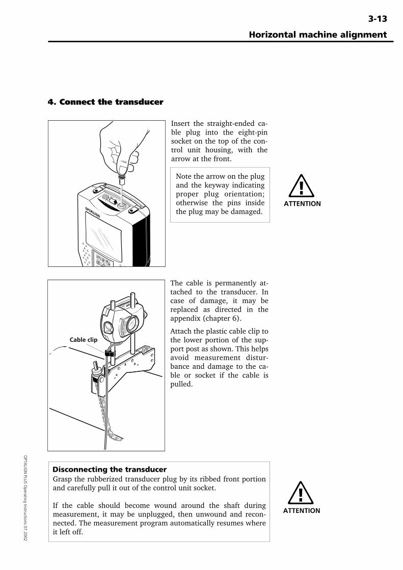
4. Connect the transducer
Horizontal machine alignment
Insert the straight-ended ca-ble plug into the eight-pinsocket on the top of the con-trol unit housing, with thearrow at the front.
Note the arrow on the plugand the keyway indicatingproper plug orientation;otherwise the pins insidethe plug may be damaged.
The cable is permanently at-tached to the transducer. Incase of damage, it may bereplaced as directed in theappendix (chapter 6).
Attach the plastic cable clip tothe lower portion of the sup-port post as shown. This helpsavoid measurement distur-bance and damage to the ca-ble or socket if the cable ispulled.
Cable clip
Disconnecting the transducerGrasp the rubberized transducer plug by its ribbed front portionand carefully pull it out of the control unit socket.
If the cable should become wound around the shaft duringmeasurement, it may be unplugged, then unwound and recon-nected. The measurement program automatically resumes whereit left off.
ATTENTION
ATTENTION
ONOFF
AUX
3-14
OPT
ALI
GN
PLU
S O
pera
ting
Inst
ruct
ions
07.
2002
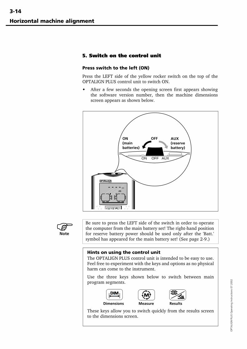
5. Switch on the control unit
Press switch to the left (ON)
Press the LEFT side of the yellow rocker switch on the top of theOPTALIGN PLUS control unit to switch ON.
� After a few seconds the opening screen first appears showingthe software version number, then the machine dimensionsscreen appears as shown below.
Horizontal machine alignment
Hints on using the control unitThe OPTALIGN PLUS control unit is intended to be easy to use.Feel free to experiment with the keys and options as no physicalharm can come to the instrument.
Use the three keys shown below to switch between mainprogram segments.
Dimensions Measure Results
These keys allow you to switch quickly from the results screento the dimensions screen.
MDIM
ON OFF AUX
ON(mainbatteries)
OFF AUX(reservebattery)
Be sure to press the LEFT side of the switch in order to operatethe computer from the main battery set! The right-hand positionfor reserve battery power should be used only after the 'Batt.'symbol has appeared for the main battery set! (See page 2-9.)
�Note
3-15
OPTA
LIGN
PLUS O
perating Instructions 07.2002
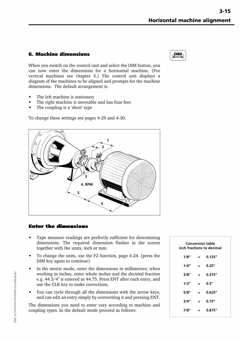
6. Machine dimensions
When you switch on the control unit and select the DIM button, youcan now enter the dimensions for a horizontal machine. (Forvertical machines see chapter 5.) The control unit displays adiagram of the machines to be aligned and prompts for the machinedimensions. The default arrangement is:
� The left machine is stationary� The right machine is moveable and has four feet� The coupling is a 'short' type
To change these settings see pages 4-29 and 4-30.
Enter the dimensions
� Tape measure readings are perfectly sufficient for determiningdimensions. The required dimension flashes in the screentogether with the units, inch or mm.
� To change the units, use the F2 function, page 4-24. (press theDIM key again to continue)
� In the metric mode, enter the dimensions in millimeters; whenworking in inches, enter whole inches and the decimal fractione.g. 44 3/4" is entered as 44.75. Press ENT after each entry, anduse the CLR key to make corrections.
� You can cycle through all the dimensions with the arrow keys,and can edit an entry simply by overwriting it and pressing ENT.
The dimensions you need to enter vary according to machine andcoupling types. In the default mode proceed as follows:
Horizontal machine alignment
1
2
3
6
5
4. RPM
Conversion tableinch fractions to decimal
1/8" = 0.125"
1/4" = 0.25"
3/8" = 0.375"
1/2" = 0.5"
5/8" = 0.625"
3/4" = 0.75"
7/8" = 0.875"
3-16
OPT
ALI
GN
PLU
S O
pera
ting
Inst
ruct
ions
07.
2002
Horizontal machine alignment
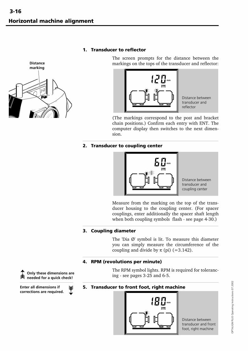
1. Transducer to reflector
The screen prompts for the distance between themarkings on the tops of the transducer and reflector:
(The markings correspond to the post and bracketchain positions.) Confirm each entry with ENT. Thecomputer display then switches to the next dimen-sion.
2. Transducer to coupling center
Measure from the marking on the top of the trans-ducer housing to the coupling center. (For spacercouplings, enter additionally the spacer shaft lengthwhen both coupling symbols flash - see page 4-30.)
3. Coupling diameter
The 'Dia Ø' symbol is lit. To measure this diameteryou can simply measure the circumference of thecoupling and divide by p (pi) (=3.142).
4. RPM (revolutions per minute)
The RPM symbol lights. RPM is required for toleranc-ing - see pages 3-25 and 6-5.
5. Transducer to front foot, right machine
Distance betweentransducer andreflector
Distance betweentransducer andcoupling center
Distance betweentransducer and frontfoot, right machine
Only these dimensions areneeded for a quick check!➳
Enter all dimensions ifcorrections are required.
➳
Distancemarking
3-17
OPTA
LIGN
PLUS O
perating Instructions 07.2002
Horizontal machine alignment
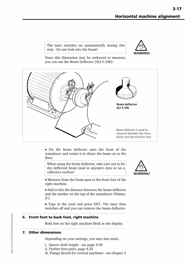
The laser switches on automatically during thisstep - Do not look into the beam!
· Fix the beam deflector onto the front of thetransducer and rotate it to direct the beam on to thefloor.
Beam deflectorALI 5.106
Beam deflector is used tomeasure between the trans-ducer and the machine foot.
Since this dimension may be awkward to measure,you can use the Beam Deflector (ALI 5.106):
WARNING!
· Measure from the beam spot to the front foot of theright machine.
· Add to this the distance between the beam deflectorand the marker on the top of the transducer (50mm/2").
· Type in the total and press ENT. The laser thenswitches off and you can remove the beam deflector.
6. Front foot to back foot, right machine
Both feet on the right machine blink in the display.
7. Other dimensions
Depending on your settings, you may also need..
i. Spacer shaft length - see page 4-30ii. Further foot pairs, page 4-24iii. Flange details for vertical machines - see chapter 5
When using the beam deflector, take care not to letthe deflected beam land in anyone's eyes or on areflective surface! WARNING!
3-18
OPT
ALI
GN
PLU
S O
pera
ting
Inst
ruct
ions
07.
2002
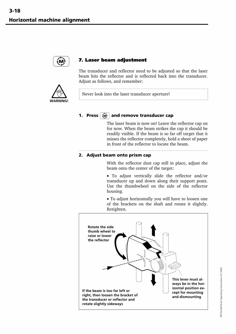
7. Laser beam adjustment
The transducer and reflector need to be adjusted so that the laserbeam hits the reflector and is reflected back into the transducer.Adjust as follows, and remember:
Never look into the laser transducer aperture!
1. Press and remove transducer cap
The laser beam is now on! Leave the reflector cap onfor now. When the beam strikes the cap it should bereadily visible. If the beam is so far off target that itmisses the reflector completely, hold a sheet of paperin front of the reflector to locate the beam.
2. Adjust beam onto prism cap
With the reflector dust cap still in place, adjust thebeam onto the center of the target:
· To adjust vertically slide the reflector and/ortransducer up and down along their support posts.Use the thumbwheel on the side of the reflectorhousing.
· To adjust horizontally you will have to loosen oneof the brackets on the shaft and rotate it slightly.Retighten.
WARNING!
Rotate the sidethumb wheel toraise or lowerthe reflector
This lever must al-ways be in the hor-izontal position ex-cept for mountingand dismounting
If the beam is too far left orright, then loosen the bracket ofthe transducer or reflector androtate slightly sideways
Horizontal machine alignment
3-19
OPTA
LIGN
PLUS O
perating Instructions 07.2002
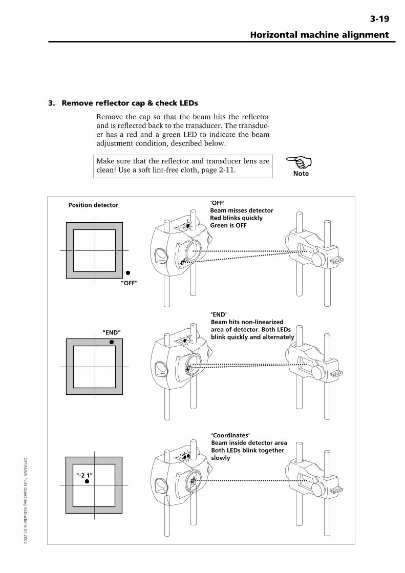
3. Remove reflector cap & check LEDs
Remove the cap so that the beam hits the reflectorand is reflected back to the transducer. The transduc-er has a red and a green LED to indicate the beamadjustment condition, described below.
Make sure that the reflector and transducer lens areclean! Use a soft lint-free cloth, page 2-11.
'OFF'Beam misses detectorRed blinks quicklyGreen is OFF
'END'Beam hits non-linearizedarea of detector. Both LEDsblink quickly and alternately
'Coordinates'Beam inside detector areaBoth LEDs blink togetherslowly
Position detector
Horizontal machine alignment
"-2 1"
"END"
"OFF"
�Note
3-20
OPT
ALI
GN
PLU
S O
pera
ting
Inst
ruct
ions
07.
2002
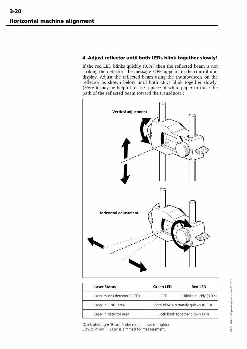
4. Adjust reflector until both LEDs blink together slowly!
If the red LED blinks quickly (0.3s) then the reflected beam is notstriking the detector: the message 'OFF' appears in the control unitdisplay. Adjust the reflected beam using the thumbwheels on thereflector as shown below until both LEDs blink together slowly.(Here it may be helpful to use a piece of white paper to trace thepath of the reflected beam toward the transducer.)
Horizontal machine alignment
Vertical adjustment
Horizontal adjustment
Laser Status Green LED Red LED
Laser misses detector ('OFF') OFF Blinks quickly (0.3 s)
Laser in 'END' area Both blink alternately quickly (0.3 s)
Laser in detector area Both blink together slowly (1 s)
Quick blinking = 'Beam-finder mode'; laser is brighter.Slow blinking = Laser is dimmed for measurement.
3-21
OPTA
LIGN
PLUS O
perating Instructions 07.2002
Do not touch components!Once zeroed, the transducer and reflector must not be touched,as any movement during measurement will be interpreted asmisalignment!
Horizontal machine alignment
�Note
Alternating
(x,y) coordi-nateof reflectedbeam
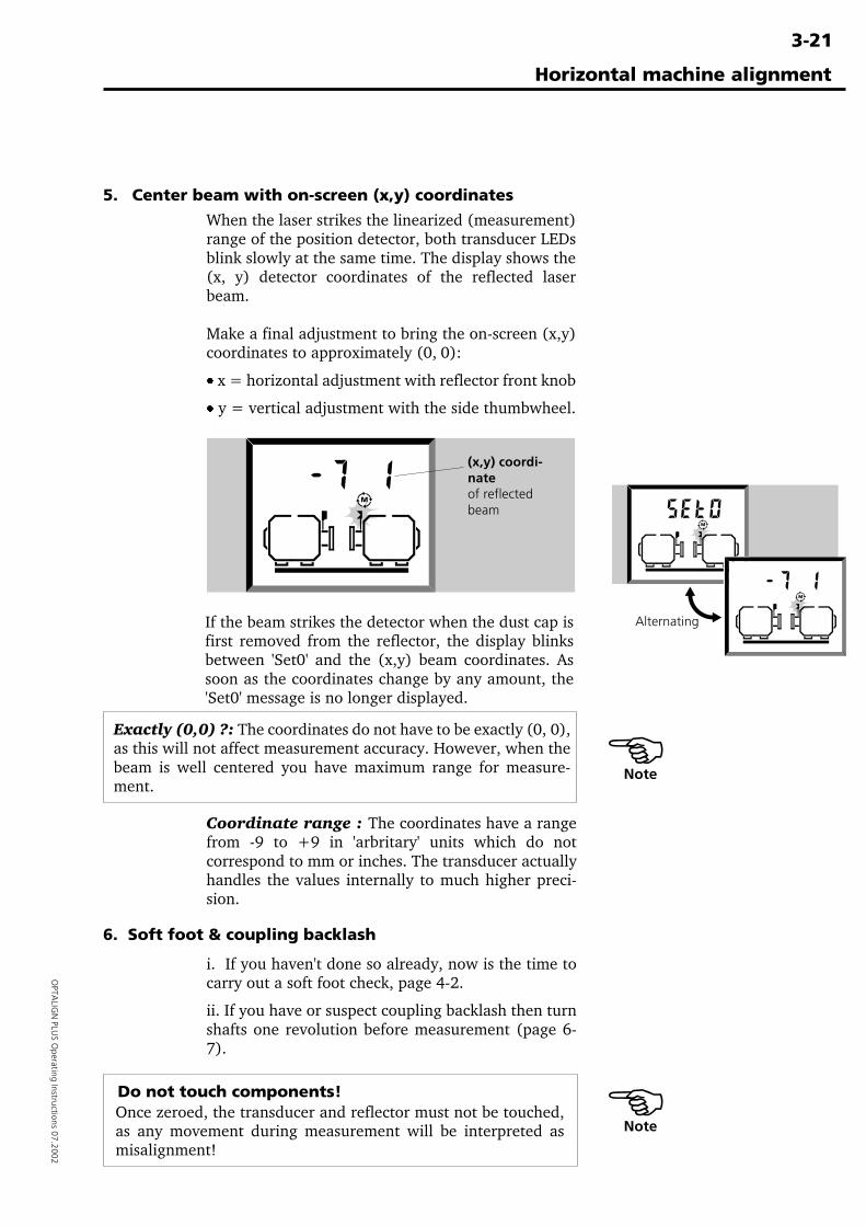
If the beam strikes the detector when the dust cap isfirst removed from the reflector, the display blinksbetween 'Set0' and the (x,y) beam coordinates. Assoon as the coordinates change by any amount, the'Set0' message is no longer displayed.
�Note
5. Center beam with on-screen (x,y) coordinates
When the laser strikes the linearized (measurement)range of the position detector, both transducer LEDsblink slowly at the same time. The display shows the(x, y) detector coordinates of the reflected laserbeam.
Make a final adjustment to bring the on-screen (x,y)coordinates to approximately (0, 0):
· x = horizontal adjustment with reflector front knob
· y = vertical adjustment with the side thumbwheel.
Exactly (0,0) ?: The coordinates do not have to be exactly (0, 0),as this will not affect measurement accuracy. However, when thebeam is well centered you have maximum range for measure-ment.
Coordinate range : The coordinates have a rangefrom -9 to +9 in 'arbritary' units which do notcorrespond to mm or inches. The transducer actuallyhandles the values internally to much higher preci-sion.
6. Soft foot & coupling backlash
i. If you haven't done so already, now is the time tocarry out a soft foot check, page 4-2.
ii. If you have or suspect coupling backlash then turnshafts one revolution before measurement (page 6-7).
3-22
OPT
ALI
GN
PLU
S O
pera
ting
Inst
ruct
ions
07.
2002
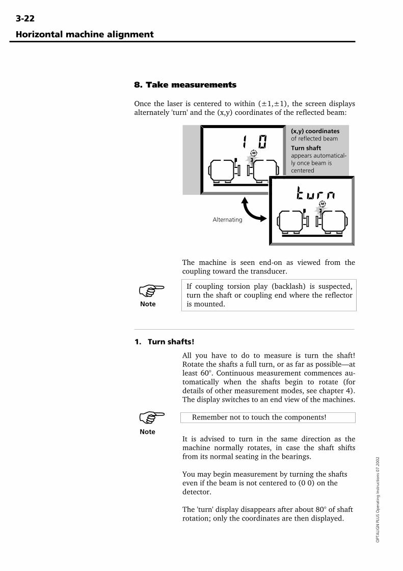
8. Take measurements
Once the laser is centered to within (±1,±1), the screen displaysalternately 'turn' and the (x,y) coordinates of the reflected beam:
The machine is seen end-on as viewed from thecoupling toward the transducer.
Horizontal machine alignment
Alternating
If coupling torsion play (backlash) is suspected,turn the shaft or coupling end where the reflectoris mounted.
1. Turn shafts!
All you have to do to measure is turn the shaft!Rotate the shafts a full turn, or as far as possible—atleast 60°. Continuous measurement commences au-tomatically when the shafts begin to rotate (fordetails of other measurement modes, see chapter 4).The display switches to an end view of the machines.
Remember not to touch the components!
It is advised to turn in the same direction as themachine normally rotates, in case the shaft shiftsfrom its normal seating in the bearings.
You may begin measurement by turning the shaftseven if the beam is not centered to (0 0) on thedetector.
The 'turn' display disappears after about 80° of shaftrotation; only the coordinates are then displayed.
�Note
�Note
Turn shaftappears automatical-ly once beam iscentered
(x,y) coordinatesof reflected beam
3-23
OPTA
LIGN
PLUS O
perating Instructions 07.2002
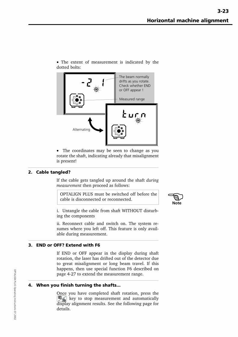
· The extent of measurement is indicated by thedotted bolts:
· The coordinates may be seen to change as yourotate the shaft, indicating already that misalignmentis present!
2. Cable tangled?
If the cable gets tangled up around the shaft duringmeasurement then proceed as follows:
Horizontal machine alignment
Alternating
Measured range
The beam normallydrifts as you rotate.Check whether ENDor OFF appear !
�Note
OPTALIGN PLUS must be switched off before thecable is disconnected or reconnected.
i. Untangle the cable from shaft WITHOUT disturb-ing the components
ii. Reconnect cable and switch on. The system re-sumes where you left off. This feature is only avail-able during measurement.
3. END or OFF? Extend with F6
If END or OFF appear in the display during shaftrotation, the laser has drifted out of the detector dueto great misalignment or long beam travel. If thishappens, then use special function F6 described onpage 4-27 to extend the measurement range.
4. When you finish turning the shafts...
Once you have completed shaft rotation, press the key to stop measurement and automatically
display alignment results. See the following page fordetails.
3-24
OPT
ALI
GN
PLU
S O
pera
ting
Inst
ruct
ions
07.
2002
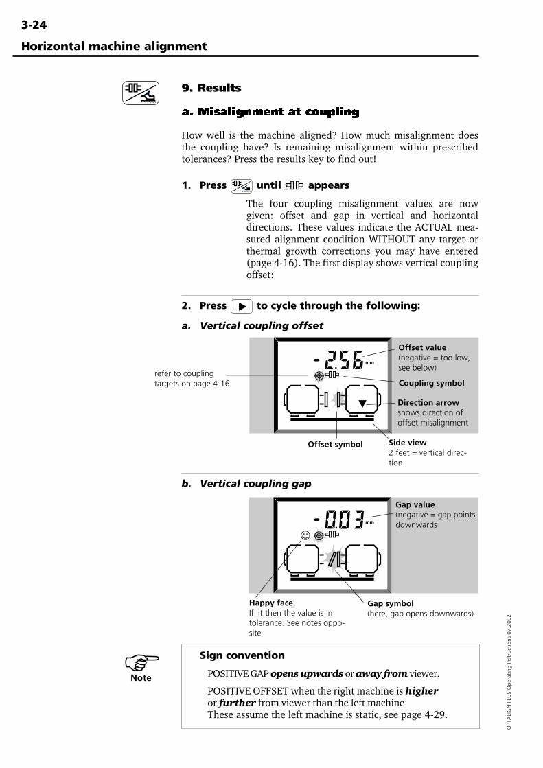
9. Results
a. Misalignment at coupling
How well is the machine aligned? How much misalignment doesthe coupling have? Is remaining misalignment within prescribedtolerances? Press the results key to find out!
1. Press until appears
The four coupling misalignment values are nowgiven: offset and gap in vertical and horizontaldirections. These values indicate the ACTUAL mea-sured alignment condition WITHOUT any target orthermal growth corrections you may have entered(page 4-16). The first display shows vertical couplingoffset:
2. Press to cycle through the following:
a. Vertical coupling offset
b. Vertical coupling gap
Sign convention
POSITIVE GAP opens upwards or away from viewer.
POSITIVE OFFSET when the right machine is higheror further from viewer than the left machineThese assume the left machine is static, see page 4-29.
Horizontal machine alignment
Side view2 feet = vertical direc-tion
Direction arrowshows direction ofoffset misalignment
Offset symbol
Offset value(negative = too low,see below)
Coupling symbol
�Note
Gap symbol(here, gap opens downwards)
Happy faceIf lit then the value is intolerance. See notes oppo-site
Gap value(negative = gap pointsdownwards
refer to couplingtargets on page 4-16
3-25
OPTA
LIGN
PLUS O
perating Instructions 07.2002
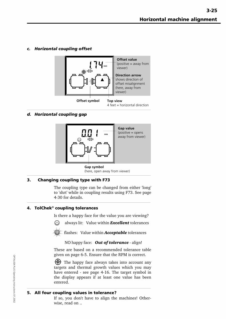
c. Horizontal coupling offset
d. Horizontal coupling gap
3. Changing coupling type with F73
The coupling type can be changed from either 'long'to 'shrt' while in coupling results using F73. See page4-30 for details.
4. TolChek® coupling tolerances
Is there a happy face for the value you are viewing?
always lit: Value within Excellent tolerances
flashes: Value within Acceptable tolerances
NO happy face: Out of tolerance - align!
These are based on a recommended tolerance tablegiven on page 6-5. Ensure that the RPM is correct.
The happy face always takes into account anytargets and thermal growth values which you mayhave entered - see page 4-16. The target symbol inthe display appears if at least one value has beenentered.
5. All four coupling values in tolerance?If so, you don't have to align the machines! Other-wise, read on ..
Horizontal machine alignment
Direction arrowshows direction ofoffset misalignment(here, away fromviewer)
Offset symbol Top view4 feet = horizontal direction
Offset value(positive = away fromviewer)
Gap symbol(here, open away from viewer)
Gap value(positive = opensaway from viewer)
3-26
OPT
ALI
GN
PLU
S O
pera
ting
Inst
ruct
ions
07.
2002
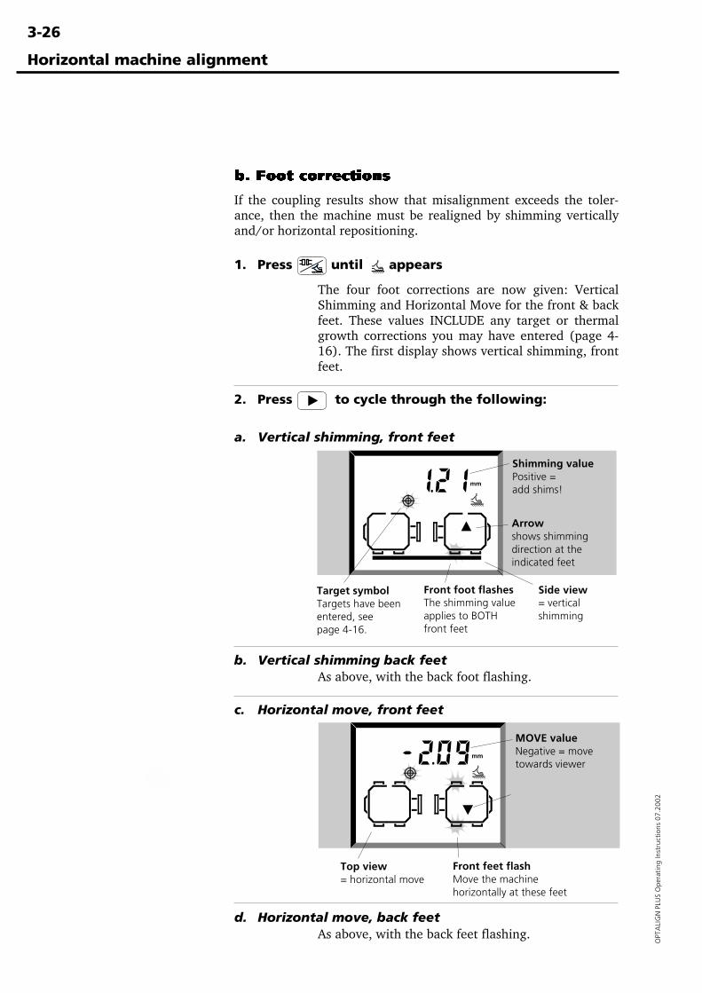
b. Foot corrections
If the coupling results show that misalignment exceeds the toler-ance, then the machine must be realigned by shimming verticallyand/or horizontal repositioning.
1. Press until appears
The four foot corrections are now given: VerticalShimming and Horizontal Move for the front & backfeet. These values INCLUDE any target or thermalgrowth corrections you may have entered (page 4-16). The first display shows vertical shimming, frontfeet.
2. Press to cycle through the following:
a. Vertical shimming, front feet
b. Vertical shimming back feetAs above, with the back foot flashing.
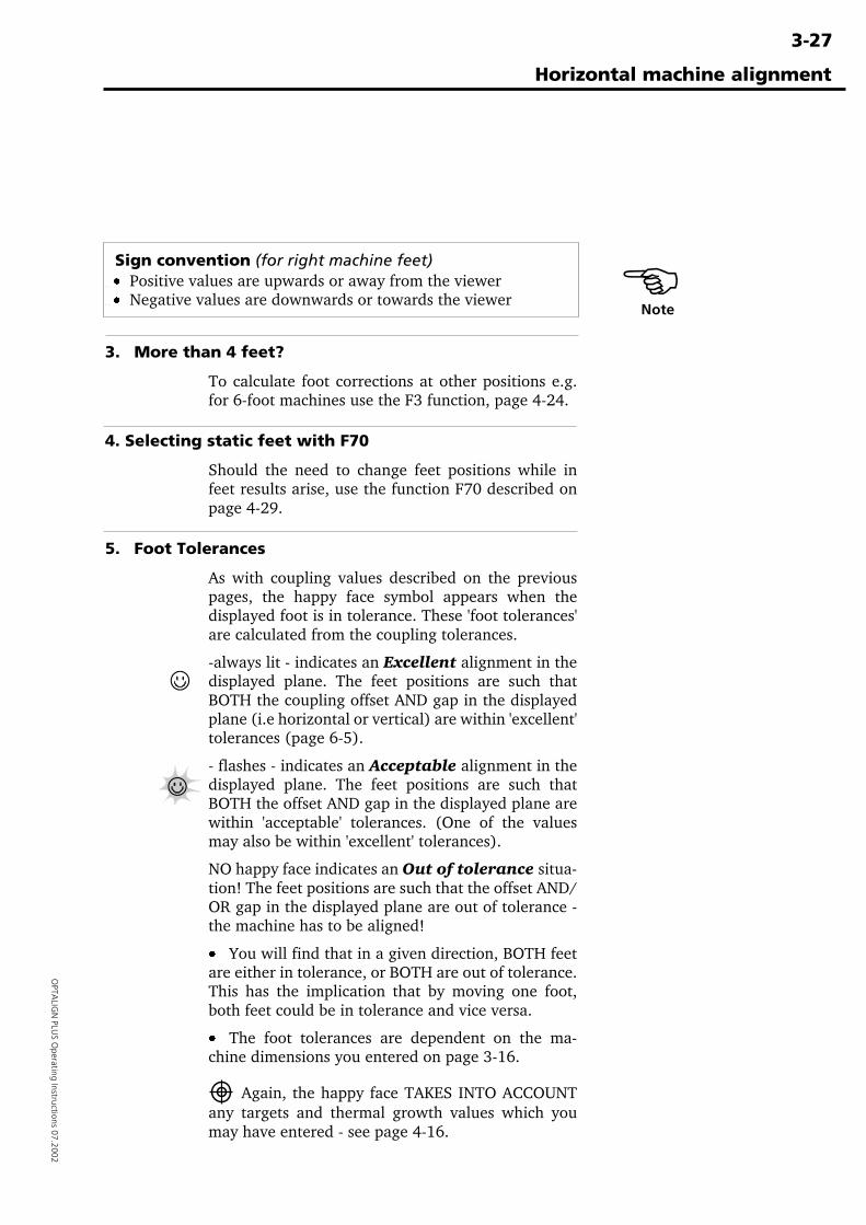
c. Horizontal move, front feet
d. Horizontal move, back feetAs above, with the back feet flashing.
Horizontal machine alignment
Target symbolTargets have beenentered, seepage 4-16.
Shimming valuePositive =add shims!
Front foot flashesThe shimming valueapplies to BOTHfront feet
Arrowshows shimmingdirection at theindicated feet
Side view= verticalshimming
Arrowshows requiredmove direction atthe indicated feet
MOVE valueNegative = movetowards viewer
Front feet flashMove the machinehorizontally at these feet
Top view= horizontal move
3-27
OPTA
LIGN
PLUS O
perating Instructions 07.2002
Horizontal machine alignment
Sign convention (for right machine feet)ÿÿ· Positive values are upwards or away from the viewerÿÿ· Negative values are downwards or towards the viewer
3. More than 4 feet?
To calculate foot corrections at other positions e.g.for 6-foot machines use the F3 function, page 4-24.
4. Selecting static feet with F70
Should the need to change feet positions while infeet results arise, use the function F70 described onpage 4-29.
5. Foot Tolerances
As with coupling values described on the previouspages, the happy face symbol appears when thedisplayed foot is in tolerance. These 'foot tolerances'are calculated from the coupling tolerances.
-always lit - indicates an Excellent alignment in thedisplayed plane. The feet positions are such thatBOTH the coupling offset AND gap in the displayedplane (i.e horizontal or vertical) are within 'excellent'tolerances (page 6-5).
- flashes - indicates an Acceptable alignment in thedisplayed plane. The feet positions are such thatBOTH the offset AND gap in the displayed plane arewithin 'acceptable' tolerances. (One of the valuesmay also be within 'excellent' tolerances).
NO happy face indicates an Out of tolerance situa-tion! The feet positions are such that the offset AND/OR gap in the displayed plane are out of tolerance -the machine has to be aligned!
· You will find that in a given direction, BOTH feetare either in tolerance, or BOTH are out of tolerance.This has the implication that by moving one foot,both feet could be in tolerance and vice versa.
· The foot tolerances are dependent on the ma-chine dimensions you entered on page 3-16.
Again, the happy face TAKES INTO ACCOUNTany targets and thermal growth values which youmay have entered - see page 4-16.
�Note
3-28
OPT
ALI
GN
PLU
S O
pera
ting
Inst
ruct
ions
07.
2002
The following pages explain how to align the machines usingthese foot correction values. Remember, if ALL the feet are intolerance, then you DON'T have to align the machines!
10. Align machine
To align your machine you need to move it vertically by shimmingthe feet, and horizontally by shifting it sideways. You could do theseoperations in either order or simultaneously, but the recommendedprocedure is generally as follows.
1) Shim firstWe recommend shimming first, unless the horizontal move issignificantly larger than the shimming corrections.
Note: if the required horizontal correction is large, e.g. more than25mm or 1", then move horizontally first. In this case the feet willmove onto a different part of the foundation, and you may need torecheck soft foot before proceeding (page 4-2).
2) RemeasureIn case the machine moved horizontally during shimming, remea-sure. Entering dimensions is not necessary.
3) MoveMonitor both vertical and horizontal move using the OPTALIGNPLUS on-screen MOVE function.
4) RemeasureTo confirm alignment, remeasure. If it is within tolerances, you'vefinished!
Vertical Shimming
1. Preparation pays!
You can save time in the long run by paying attentionto the machine preparation requirements on page 3-7! To successfully shim the machine you should havemet those requirements already, in particular:
i. The foot bolts are clean, intact & removeable,
ii. Soft foot has been eliminated (page 4-2),
iii. The feet have enough shims under them shouldyou have to lower the machine,
iv. You have a set of good quality shims available e.g.LAMIBLOC or PERMABLOC (page 6-9).
2. Loosen bolts
Try not to inadvertently move the machine horizon-tally. If any foot comes off the ground when loosenedthen you have soft foot! - see page 4-2.
Horizontal machine alignment
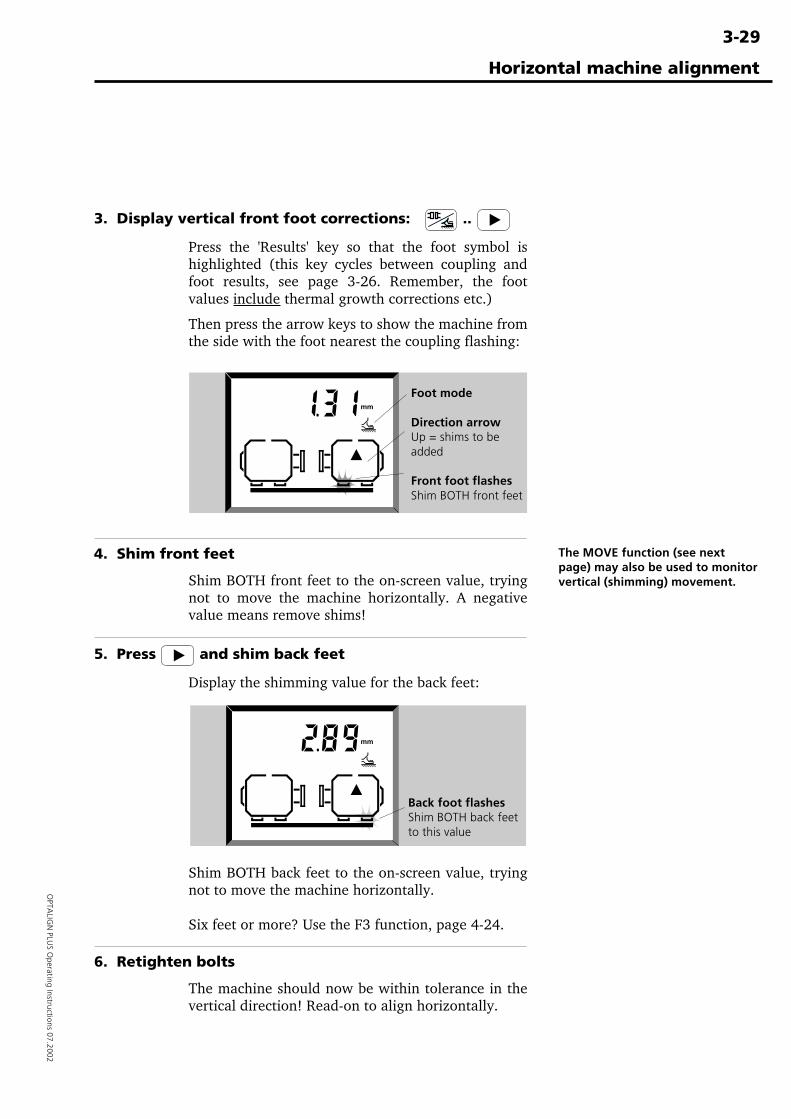
3-29
OPTA
LIGN
PLUS O
perating Instructions 07.2002
3. Display vertical front foot corrections: ..
Press the 'Results' key so that the foot symbol ishighlighted (this key cycles between coupling andfoot results, see page 3-26. Remember, the footvalues include thermal growth corrections etc.)
Then press the arrow keys to show the machine fromthe side with the foot nearest the coupling flashing:
4. Shim front feet
Shim BOTH front feet to the on-screen value, tryingnot to move the machine horizontally. A negativevalue means remove shims!
5. Press and shim back feet
Display the shimming value for the back feet:
Shim BOTH back feet to the on-screen value, tryingnot to move the machine horizontally.
Six feet or more? Use the F3 function, page 4-24.
6. Retighten bolts
The machine should now be within tolerance in thevertical direction! Read-on to align horizontally.
Horizontal machine alignment
Foot mode
Direction arrowUp = shims to beadded
Front foot flashesShim BOTH front feet
Back foot flashesShim BOTH back feetto this value
The MOVE function (see nextpage) may also be used to monitorvertical (shimming) movement.
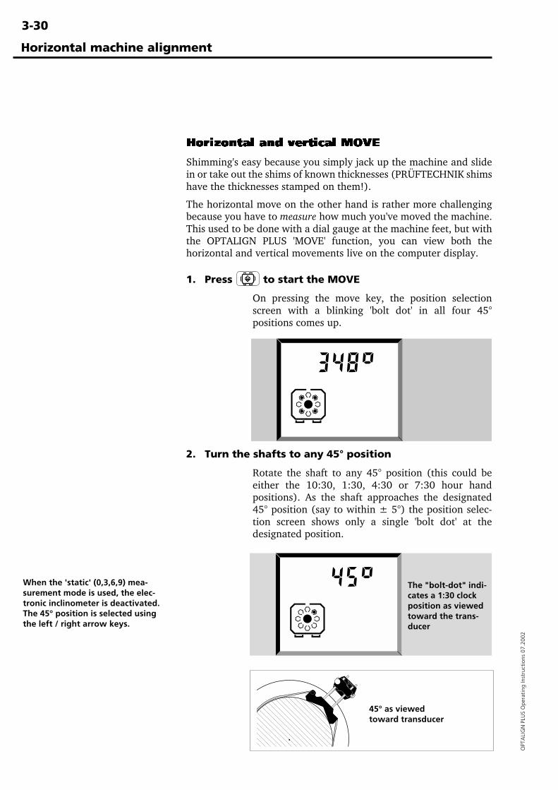
3-30
OPT
ALI
GN
PLU
S O
pera
ting
Inst
ruct
ions
07.
2002
Horizontal machine alignment
Horizontal and vertical MOVE
Shimming's easy because you simply jack up the machine and slidein or take out the shims of known thicknesses (PRÜFTECHNIK shimshave the thicknesses stamped on them!).
The horizontal move on the other hand is rather more challengingbecause you have to measure how much you've moved the machine.This used to be done with a dial gauge at the machine feet, but withthe OPTALIGN PLUS 'MOVE' function, you can view both thehorizontal and vertical movements live on the computer display.
1. Press to start the MOVE
On pressing the move key, the position selectionscreen with a blinking 'bolt dot' in all four 45°positions comes up.
2. Turn the shafts to any 45° position
Rotate the shaft to any 45° position (this could beeither the 10:30, 1:30, 4:30 or 7:30 hour handpositions). As the shaft approaches the designated45° position (say to within ± 5°) the position selec-tion screen shows only a single 'bolt dot' at thedesignated position.
When the 'static' (0,3,6,9) mea-surement mode is used, the elec-tronic inclinometer is deactivated.The 45° position is selected usingthe left / right arrow keys.
45° as viewedtoward transducer
The "bolt-dot" indi-cates a 1:30 clockposition as viewedtoward the trans-ducer
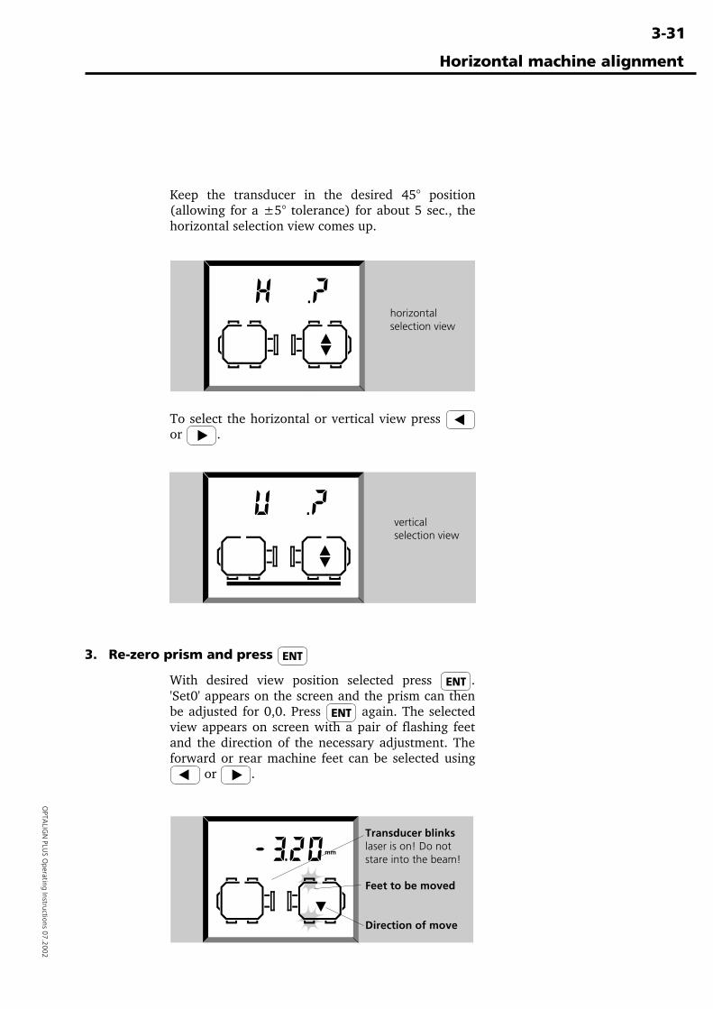
3-31
OPTA
LIGN
PLUS O
perating Instructions 07.2002
Horizontal machine alignment
Keep the transducer in the desired 45° position(allowing for a ±5° tolerance) for about 5 sec., thehorizontal selection view comes up.
Transducer blinkslaser is on! Do notstare into the beam!
Feet to be moved
Direction of move
horizontalselection view
verticalselection view
To select the horizontal or vertical view press or .
3. Re-zero prism and press
With desired view position selected press .'Set0' appears on the screen and the prism can thenbe adjusted for 0,0. Press again. The selectedview appears on screen with a pair of flashing feetand the direction of the necessary adjustment. Theforward or rear machine feet can be selected using
or .
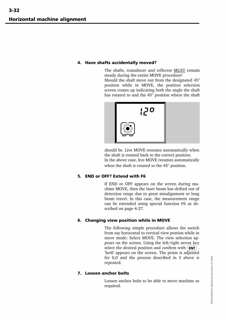
3-32
OPT
ALI
GN
PLU
S O
pera
ting
Inst
ruct
ions
07.
2002
Horizontal machine alignment
4. Have shafts accidentally moved?
The shafts, transducer and reflector MUST remainsteady during the entire MOVE procedure!Should the shaft move out from the designated 45°position while in MOVE, the position selectionscreen comes up indicating both the angle the shafthas rotated to and the 45° position where the shaft
should be. Live MOVE resumes automatically whenthe shaft is rotated back to the correct position.In the above case, live MOVE resumes automaticallywhen the shaft is rotated to the 45° position.
5. END or OFF? Extend with F6
If END or OFF appears on the screen during ma-chine MOVE, then the laser beam has drifted out ofdetection range due to great misalignment or longbeam travel. In this case, the measurement rangecan be extended using special function F6 as de-scribed on page 4-27.
6. Changing view position while in MOVE
The following simple procedure allows the switchfrom say horizontal to vertical view postion while inmove mode: Select MOVE. The view selection ap-pears on the screen. Using the left/right arrow keyselect the desired position and confirm with .'Set0' appears on the screen. The prism is adjustedfor 0,0 and the process described in 3 above isrepeated.
7. Loosen anchor bolts
Loosen anchor bolts to be able to move machine asrequired.
3-33
OPTA
LIGN
PLUS O
perating Instructions 07.2002
Horizontal machine alignment
8. Observe and move flashing feet
· Move the machine at the indicated feet in thedirection indicated by the arrow.
· The display automatically displays the value for thefeet furthest out of line (see overleaf for details), sowatch the screen carefully to see which end youshould be moving!
· You can briefly display the value at the other footby pressing either the ENT key or the left/right arrowkeys.
Temptation may be great to move the machinewith a few hefty blows of a sledgehammer. Thiscan cause not only bearing damage, but also lessaccurate MOVE results. Jack bolts on the feet orother mechanical or hydraulic devices are recom-mended.
Notes: During the MOVE..
Display switchingAs one end of the machine is brought to within half theremaining correction for the feet at the other end, the computerswitches automatically to the other end, and causing the othermachine foot to blink.
Please pay careful attention to the following points:• Which foot is flashing in the display?• When does the display jump to the other foot?• In which direction is the arrow pointing?
Nearing zero : watch for the happy faceProceed towards zero at both machine ends until the happy facesymbol appears (lit=excellent, blinking=acceptable tolerances,see page 3-25 for details).
Soft footIf the machine suffers from excessive soft foot, the MOVEfunction may be hampered by the fact that the machine changesits position on its own every time the bolts are loosened andtightened. Do correct this before aligning (page 4-2).
Note�
3-34
OPT
ALI
GN
PLU
S O
pera
ting
Inst
ruct
ions
07.
2002
Horizontal machine alignment
9. Tighten the anchor bolts
If the machine moves back out of alignment whenyou retighten the bolts, then first check for soft foot.If it still occurs then note down how much themachine moves horizontally when the bolts aretightened, and try to compensate for it during the'Move' procedure.
10. Final check : In tolerance?
Since the machine has been moved, earlier resultsare no longer valid, so press the 'M' key and takeanother measurement.
View the results. If they are in tolerance then yourmachines are aligned!
11. Alignment completion
This completes the horizontal alignment!
Remove the components from the shafts and replace guardsbefore you switch the machine back on!
1. If you experience poor repeatability..
Possible causes are:
· Incorrect or loose bracket mounting, page 3-8
· Significant shaft play or coupling backlash, page 6-7
· Soft foot, page 4-2, can cause positioning errorsthat make repeat measurement necessary
See also see the troubleshooting guide, page 6-32.
2. Saving data and printing
See the following page for instructions to save andprint your data.
3. ...and finally,
Switch off the control unit and store the componentsin their case! If the system is not to be used for sometime then remove the batteries (page 2-7).
WARNING!
3-35
OPTA
LIGN
PLUS O
perating Instructions 07.2002
Horizontal machine alignment
12. Saving data and printing
Before you switch off you can save your dimensions, measurements,results and all settings in a numbered file in the OPTALIGN PLUSnon-volatile memory. The files are numbered from 1 to 99 (0 isreserved for the most recent data set, see below). This memory isretained even when the computer is switched off.
1. To save press
no. x appears where x is the number of the firstempty file. Press ENT to save the data with thisnumber.
To store with a different number, enter the numberand press ENT. If that file already exists, the screenwill blink and you must press ENT again to overwritethe existing file. If you don't want to overwrite thentry another number or press any function button(e.g. DIM) to cancel the whole operation. A row ofdashes progresses from left to right during thestorage process.
Keep a separate record of important data!PRÜFTECHNIK AG assumes no responsibility forlosses!
Alternatively, use the OPTALIGN PLUS ExplorerPC interface program. (See Chapter 6)
2. To load press
Before loading, make sure you save whatever you'recurrently working on if needed. Then press the LOADkey, enter the required file number and press ENT.
'Resume' function (file '0')File number '0' is reserved as a Resume function.When you switch OPTALIGN PLUS on, press theLOAD key and enter '0' ENT to recall the last non-saved set of measurement data.
3. To print connect printer and press
Using the supplied adapter/converter any PC com-patible printer should work with OPTALIGN PLUS .See page 2-14 for details.
The transducer must be connected to the controlunit whenever a printout is to be made, since thedata memory and operating program are locatedin the transducer.
�Note
�Note
3-36
OPT
ALI
GN
PLU
S O
pera
ting
Inst
ruct
ions
07.
2002
· Laser printers (e.g. HP LaserJet) should be set tothe 'PC-8' font.
· The serial parameters set in OPTALIGN PLUS are:Baudrate = 9600, Data bits = 8,Parity = None, Stop bits = 1Check your printer manual to ensure printercompatability with these settings.
These settings are also used for PC data transfer.
Once connected, press the PRINT key. The green LEDon the data converter blinks (red LED = interrup-tion) and a printout similar to that shown on page 6-24 appears.
Problems? See the troubleshooting guide, page 6-32.
13. Hot alignment check
At some point, you may want to check the alignment of a machineset that has been running long enough to reach its 'steady state'('hot') operating condition. In that case, the OPTALIGN PLUSsystem can be used to take 'hot' alignment readings in a matter of afew minutes after the machines are shut off.
The procedure described below saves time by allowing you to beginmeasurement immediately after turning on your OPTALIGN PLUScontrol unit, i.e. without entering machine dimensions first.
1. As soon as the shafts have stopped rotating, mountthe components and connect the transducer to thecontrol unit (see pages 3-8 to 3-13).
2. Switch on the control unit and press the M key.
3. Center the laser beam on the detector (0 0) (seepages 3-18 to 3-21), then turn the shafts in theirnormal direction of operation by at least 60°.
4. Press the results key to stop measurement.
5. The display automatically prompts for machinedimension as needed. Once all dimensions are en-tered, the alignment condition is automatically cal-culated and displayed.
.
�Note
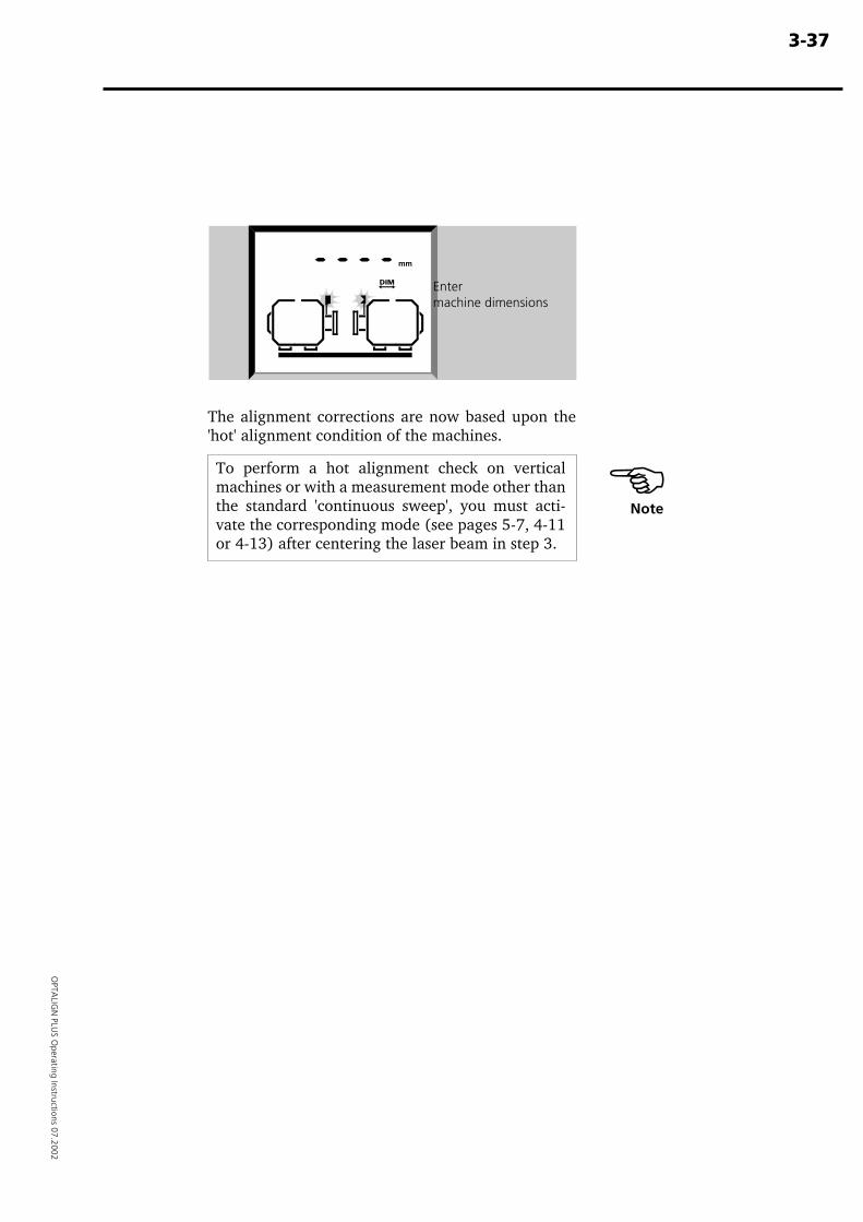
3-37
OPTA
LIGN
PLUS O
perating Instructions 07.2002
The alignment corrections are now based upon the'hot' alignment condition of the machines.
To perform a hot alignment check on verticalmachines or with a measurement mode other thanthe standard 'continuous sweep', you must acti-vate the corresponding mode (see pages 5-7, 4-11or 4-13) after centering the laser beam in step 3.
Entermachine dimensions
Note�

3-3
8
OPTALIGN PLUS Operating Instructions 07.2002
( Page left blank intentionally )
4-1
OPTA
LIGN
PLUS O
perating Instructions 07.2002
Further functions
Chapter 4: Further functions
You have now mastered the straight-through alignnment procedurefor standard horizontal machines. We now describe the manyspecial functions and settings available in OPTALIGN PLUS.
Chapter 1 Introduction .......................................1-1 to 1-12
Chapter 2 Description .........................................2-1 to 2-14
Chapter 3 Horizontal alignment ........................3-1 to 3-38
Chapter 4: Further functions .......................................... 4-1Soft foot ....................................................................................... 4-2
Soft foot procedure .................................................................. 4-4Determining soft foot corrections ............................................ 4-6
Measurement modes ................................................................... 4-8Continuous Sweep mode ......................................................... 4-8Multipoint mode ('Pt.') ........................................................... 4-10Static (0369) measurement mode ......................................... 4-12Measuring a non-rotatable shaft ............................................ 4-14
Coupling targets & thermal growth at feet ................................ 4-161. Coupling targets for 'cold' alignment ................................. 4-172. Expected thermal growth at the machine feet ................... 4-203. Thermal growth for stationary machine ............................ 4-21
'F' key functions ......................................................................... 4-22F1 : Display (x,y) coordinates and rotation angle .................. 4-23F2 : Select mm/inch units ...................................................... 4-24F3 : 6-foot machines .............................................................. 4-24F4 : Display time and date ..................................................... 4-26F6 : Extending the measurement range ................................. 4-27F70 : Select static machine/feet ............................................. 4-29F71 : Select report format (graphic/text) .............................. 4-29F73 : Coupling type ............................................................... 4-30F74–F99 : Setting defaults, time, resetting, etc ...................... 4-32PC connection ........................................................................ 4-35Lists ....................................................................................... 4-35Display viewer ....................................................................... 4-36
Chapter 5 Vertical alignment .............................5-1 to 5-18
Chapter 6 Appendix ............................................6-1 to 6-50
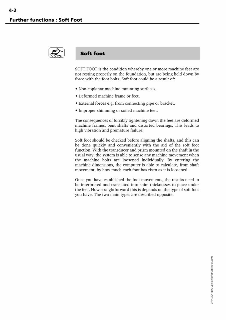
4-2
OPT
ALI
GN
PLU
S O
pera
ting
Inst
ruct
ions
07.
2002
Soft foot
SOFT FOOT is the condition whereby one or more machine feet arenot resting properly on the foundation, but are being held down byforce with the foot bolts. Soft foot could be a result of:
� Non-coplanar machine mounting surfaces,
� Deformed machine frame or feet,
� External forces e.g. from connecting pipe or bracket,
� Improper shimming or soiled machine feet.
The consequences of forcibly tightening down the feet are deformedmachine frames, bent shafts and distorted bearings. This leads tohigh vibration and premature failure.
Soft foot should be checked before aligning the shafts, and this canbe done quickly and conveniently with the aid of the soft footfunction. With the transducer and prism mounted on the shaft in theusual way, the system is able to sense any machine movement whenthe machine bolts are loosened individually. By entering themachine dimensions, the computer is able to calculate, from shaftmovement, by how much each foot has risen as it is loosened.
Once you have established the foot movements, the results need tobe interpreted and translated into shim thicknesses to place underthe feet. How straightforward this is depends on the type of soft footyou have. The two main types are described opposite.
Further functions : Soft Foot
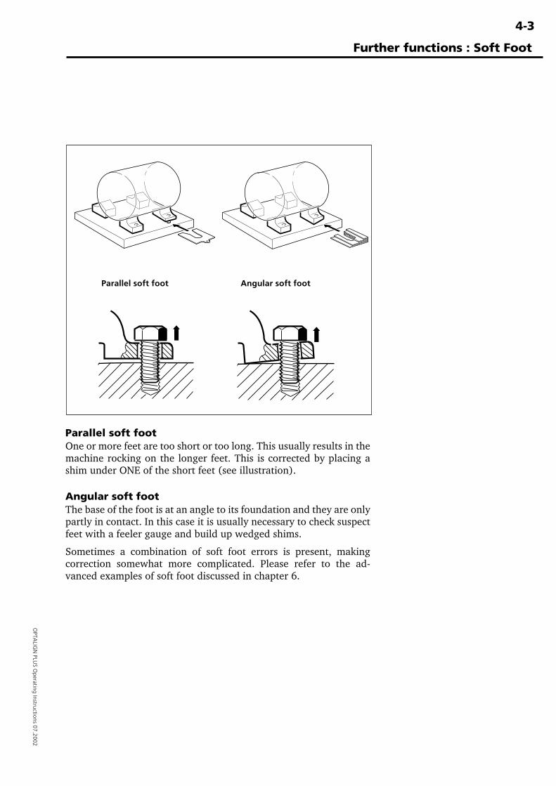
4-3
OPTA
LIGN
PLUS O
perating Instructions 07.2002
Further functions : Soft Foot
Parallel soft foot Angular soft foot
Parallel soft footOne or more feet are too short or too long. This usually results in themachine rocking on the longer feet. This is corrected by placing ashim under ONE of the short feet (see illustration).
Angular soft footThe base of the foot is at an angle to its foundation and they are onlypartly in contact. In this case it is usually necessary to check suspectfeet with a feeler gauge and build up wedged shims.
Sometimes a combination of soft foot errors is present, makingcorrection somewhat more complicated. Please refer to the ad-vanced examples of soft foot discussed in chapter 6.
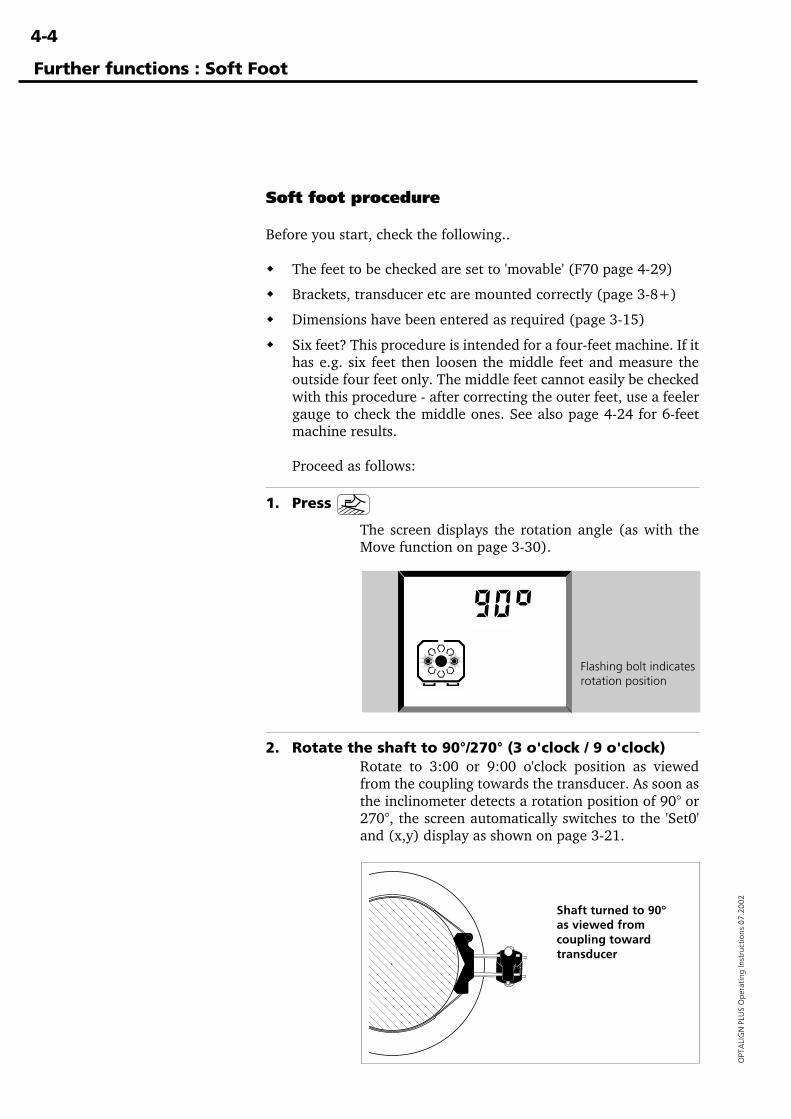
4-4
OPT
ALI
GN
PLU
S O
pera
ting
Inst
ruct
ions
07.
2002
Soft foot procedure
Before you start, check the following..
� The feet to be checked are set to 'movable' (F70 page 4-29)
� Brackets, transducer etc are mounted correctly (page 3-8+)
� Dimensions have been entered as required (page 3-15)
� Six feet? This procedure is intended for a four-feet machine. If ithas e.g. six feet then loosen the middle feet and measure theoutside four feet only. The middle feet cannot easily be checkedwith this procedure - after correcting the outer feet, use a feelergauge to check the middle ones. See also page 4-24 for 6-feetmachine results.
Proceed as follows:
1. Press
The screen displays the rotation angle (as with theMove function on page 3-30).
2. Rotate the shaft to 90°/270° (3 o'clock / 9 o'clock)Rotate to 3:00 or 9:00 o'clock position as viewedfrom the coupling towards the transducer. As soon asthe inclinometer detects a rotation position of 90° or270°, the screen automatically switches to the 'Set0'and (x,y) display as shown on page 3-21.
Flashing bolt indicatesrotation position
Further functions : Soft Foot
Shaft turned to 90°as viewed fromcoupling towardtransducer
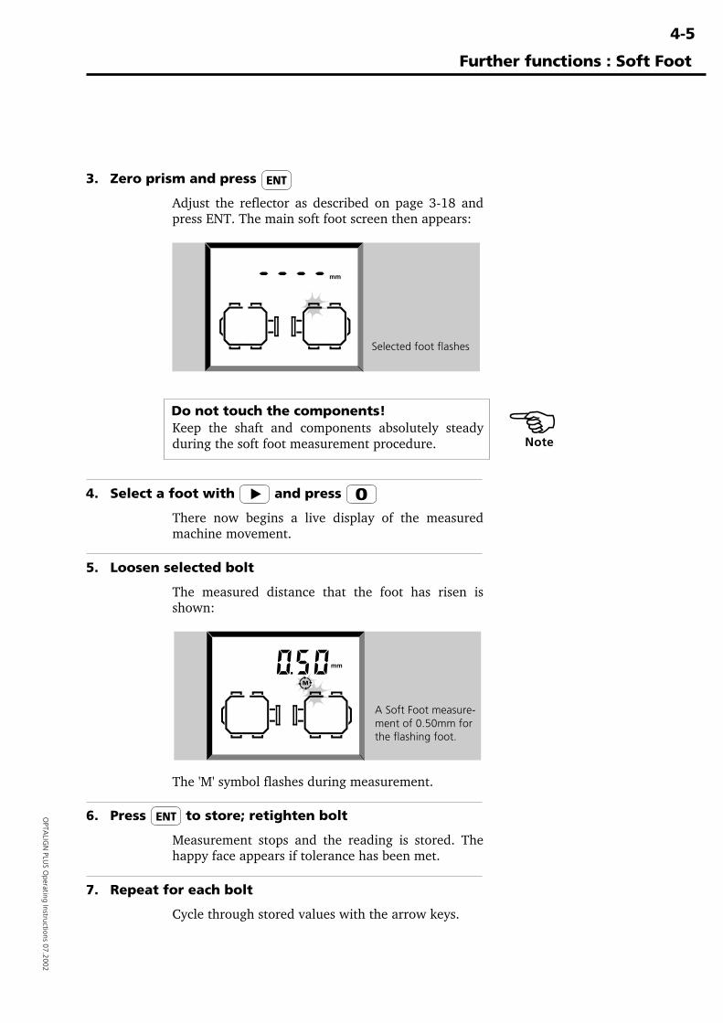
4-5
OPTA
LIGN
PLUS O
perating Instructions 07.2002
3. Zero prism and press
Adjust the reflector as described on page 3-18 andpress ENT. The main soft foot screen then appears:
Do not touch the components!Keep the shaft and components absolutely steadyduring the soft foot measurement procedure.
4. Select a foot with and press
There now begins a live display of the measuredmachine movement.
5. Loosen selected bolt
The measured distance that the foot has risen isshown:
The 'M' symbol flashes during measurement.
6. Press to store; retighten bolt
Measurement stops and the reading is stored. Thehappy face appears if tolerance has been met.
7. Repeat for each bolt
Cycle through stored values with the arrow keys.
Further functions : Soft Foot
�Note
Selected foot flashes
A Soft Foot measure-ment of 0.50mm forthe flashing foot.
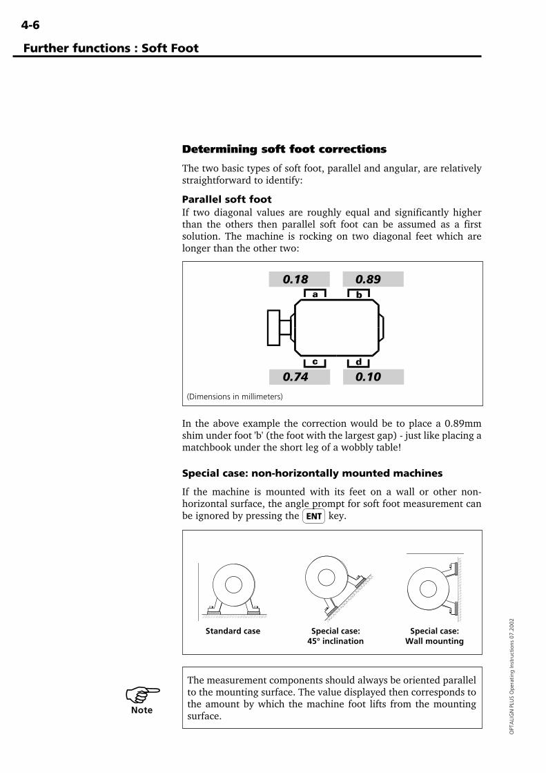
4-6
OPT
ALI
GN
PLU
S O
pera
ting
Inst
ruct
ions
07.
2002
Determining soft foot corrections
The two basic types of soft foot, parallel and angular, are relativelystraightforward to identify:
Parallel soft footIf two diagonal values are roughly equal and significantly higherthan the others then parallel soft foot can be assumed as a firstsolution. The machine is rocking on two diagonal feet which arelonger than the other two:
In the above example the correction would be to place a 0.89mmshim under foot 'b' (the foot with the largest gap) - just like placing amatchbook under the short leg of a wobbly table!
Further functions : Soft Foot
(Dimensions in millimeters)
0.18 0.89
0.74 0.10
Special case: non-horizontally mounted machines
If the machine is mounted with its feet on a wall or other non-horizontal surface, the angle prompt for soft foot measurement canbe ignored by pressing the key.
Standard case Special case: Special case:45° inclination Wall mounting
The measurement components should always be oriented parallelto the mounting surface. The value displayed then corresponds tothe amount by which the machine foot lifts from the mountingsurface.
�Note
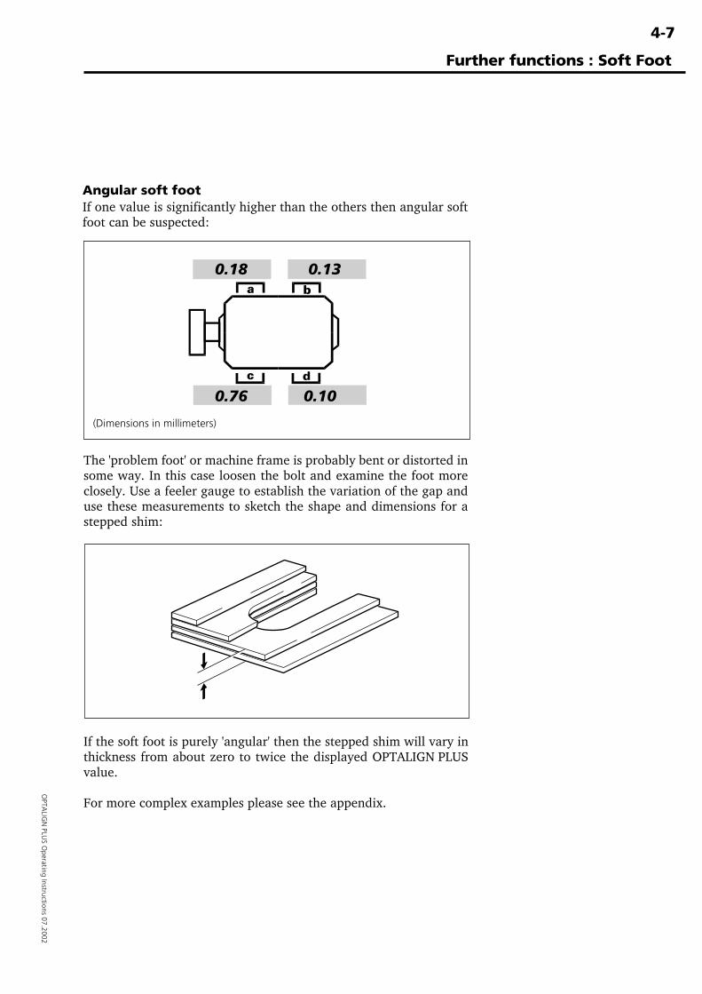
4-7
OPTA
LIGN
PLUS O
perating Instructions 07.2002
Angular soft footIf one value is significantly higher than the others then angular softfoot can be suspected:
If the soft foot is purely 'angular' then the stepped shim will vary inthickness from about zero to twice the displayed OPTALIGN PLUSvalue.
For more complex examples please see the appendix.
The 'problem foot' or machine frame is probably bent or distorted insome way. In this case loosen the bolt and examine the foot moreclosely. Use a feeler gauge to establish the variation of the gap anduse these measurements to sketch the shape and dimensions for astepped shim:
Further functions : Soft Foot
(Dimensions in millimeters)
0.18 0.13
0.76 0.10
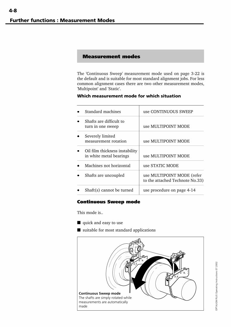
4-8
OPT
ALI
GN
PLU
S O
pera
ting
Inst
ruct
ions
07.
2002
Measurement modes
The 'Continuous Sweep' measurement mode used on page 3-22 isthe default and is suitable for most standard alignment jobs. For lesscommon alignment cases there are two other measurement modes,'Multipoint' and 'Static'.
Further functions : Measurement Modes
Continuous Sweep mode
This mode is..
■ quick and easy to use
■ suitable for most standard applications
Continuous Sweep modeThe shafts are simply rotated whilemeasurements are automaticallymade
Which measurement mode for which situation
· Standard machines use CONTINUOUS SWEEP
· Shafts are difficult toturn in one sweep use MULTIPOINT MODE
· Severely limitedmeasurement rotation use MULTIPOINT MODE
· Oil film thickness instabilityin white metal bearings use MULTIPOINT MODE
· Machines not horizontal use STATIC MODE
· Shafts are uncoupled use MULTIPOINT MODE (referto the attached Technote No.33)
· Shaft(s) cannot be turned use procedure on page 4-14
4-9
OPTA
LIGN
PLUS O
perating Instructions 07.2002
Further functions : Measurement Modes
This is the measurement mode described in the standard horizontalalignment procedure (page 3-22) and is recommended for moststandard cases.
ProcedureTurn the shaft through one complete turn, or as far as possible - atleast 60°. You can turn in either direction, but it is advised to turn inthe same direction the machine normally rotates. This ensures theshafts don't move out of their normal seated position within thebearings, which would alter the alignment measurement.
The measurement process actually stops only once the Resultskey has been pressed.
How it works:In the 'Continuous Sweep' mode the transducer is continuouslyreading its built-in electronic inclinometer. When shaft rotation issensed, the coordinates of the reflected laser beam on the detectorare measured and stored together with the shaft angle; the slowerthe shafts are rotated, the more numerous and the closer togetherthese measurements will be.
The measurement precision is much higher than the single digitcoordinates displayed on the screen, as you can see for yourself withthe F1 function described on page 4-23.
Over 100 measurements can be made during rotation which areprocessed by the OPTALIGN PLUS computer to give a very accuratealignment result.
Minimising effect of coupling backlashMeasurements are not recorded during the first 5° of shaft rotationto prevent coupling backlash from affecting results. See page 6-7 forfurther details.
�Note
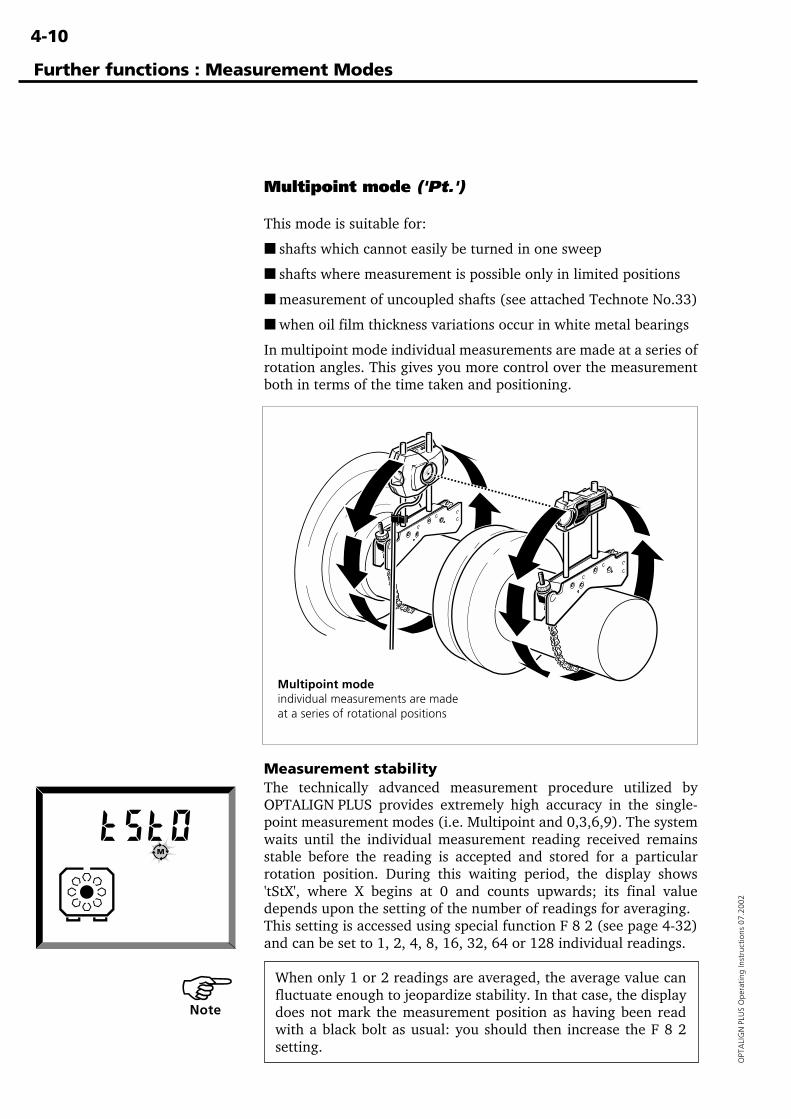
4-10
OPT
ALI
GN
PLU
S O
pera
ting
Inst
ruct
ions
07.
2002
Multipoint mode ('Pt.')
This mode is suitable for:
■ shafts which cannot easily be turned in one sweep
■ shafts where measurement is possible only in limited positions
■ measurement of uncoupled shafts (see attached Technote No.33)
■ when oil film thickness variations occur in white metal bearings
In multipoint mode individual measurements are made at a series ofrotation angles. This gives you more control over the measurementboth in terms of the time taken and positioning.
Multipoint modeindividual measurements are madeat a series of rotational positions
Further functions : Measurement Modes
Measurement stabilityThe technically advanced measurement procedure utilized byOPTALIGN PLUS provides extremely high accuracy in the single-point measurement modes (i.e. Multipoint and 0,3,6,9). The systemwaits until the individual measurement reading received remainsstable before the reading is accepted and stored for a particularrotation position. During this waiting period, the display shows'tStX', where X begins at 0 and counts upwards; its final valuedepends upon the setting of the number of readings for averaging.This setting is accessed using special function F 8 2 (see page 4-32)and can be set to 1, 2, 4, 8, 16, 32, 64 or 128 individual readings.
When only 1 or 2 readings are averaged, the average value canfluctuate enough to jeopardize stability. In that case, the displaydoes not mark the measurement position as having been readwith a black bolt as usual: you should then increase the F 8 2setting.
�Note
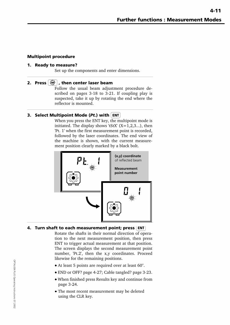
4-11
OPTA
LIGN
PLUS O
perating Instructions 07.2002
Multipoint procedure
1. Ready to measure?Set up the components and enter dimensions.
2. Press , then center laser beamFollow the usual beam adjustment procedure de-scribed on pages 3-18 to 3-21. If coupling play issuspected, take it up by rotating the end where thereflector is mounted.
3. Select Multipoint Mode (Pt.) with When you press the ENT key, the multipoint mode isinitiated. The display shows 'tStX' (X=1,2,3...), then'Pt. 1' when the first measurement point is recorded,followed by the laser coordinates. The end view ofthe machine is shown, with the current measure-ment position clearly marked by a black bolt.
4. Turn shaft to each measurement point; press Rotate the shafts in their normal direction of opera-tion to the next measurement position, then pressENT to trigger actual measurement at that position.The screen displays the second measurement pointnumber, 'Pt.2', then the x,y coordinates. Proceedlikewise for the remaining positions.
· At least 5 points are required over at least 60°.
· END or OFF? page 4-27; Cable tangled? page 3-23.
· When finished press Results key and continue from page 3-24.
· The most recent measurement may be deleted using the CLR key.
Further functions : Measurement Modes
(x,y) coordinateof reflected beam
Measurementpoint number
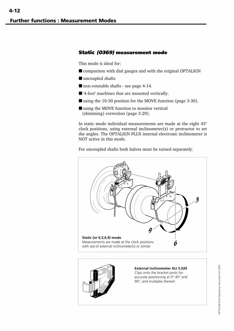
4-12
OPT
ALI
GN
PLU
S O
pera
ting
Inst
ruct
ions
07.
2002
Further functions : Measurement Modes
Static (0369) measurement mode
This mode is ideal for:
■ comparison with dial gauges and with the original OPTALIGN
■ uncoupled shafts
■ non-rotatable shafts - see page 4-14.
■ '4-feet' machines that are mounted vertically.
■ using the 10:30 position for the MOVE function (page 3-30).
■ using the MOVE function to monitor vertical (shimming) correction (page 3-29).
In static mode individual measurements are made at the eight 45°clock positions, using external inclinometer(s) or protractor to setthe angles. The OPTALIGN PLUS internal electronic inclinometer isNOT active in this mode.
For uncoupled shafts both halves must be turned separately.
Static (or 0,3,6,9) modeMeasurements are made at the clock positionswith aid of external inclinometer(s) or similar
External inclinometer ALI 5.020Clips onto the bracket posts foraccurate positioning at 0° 45° and90°, and multiples thereof.
3
6
9
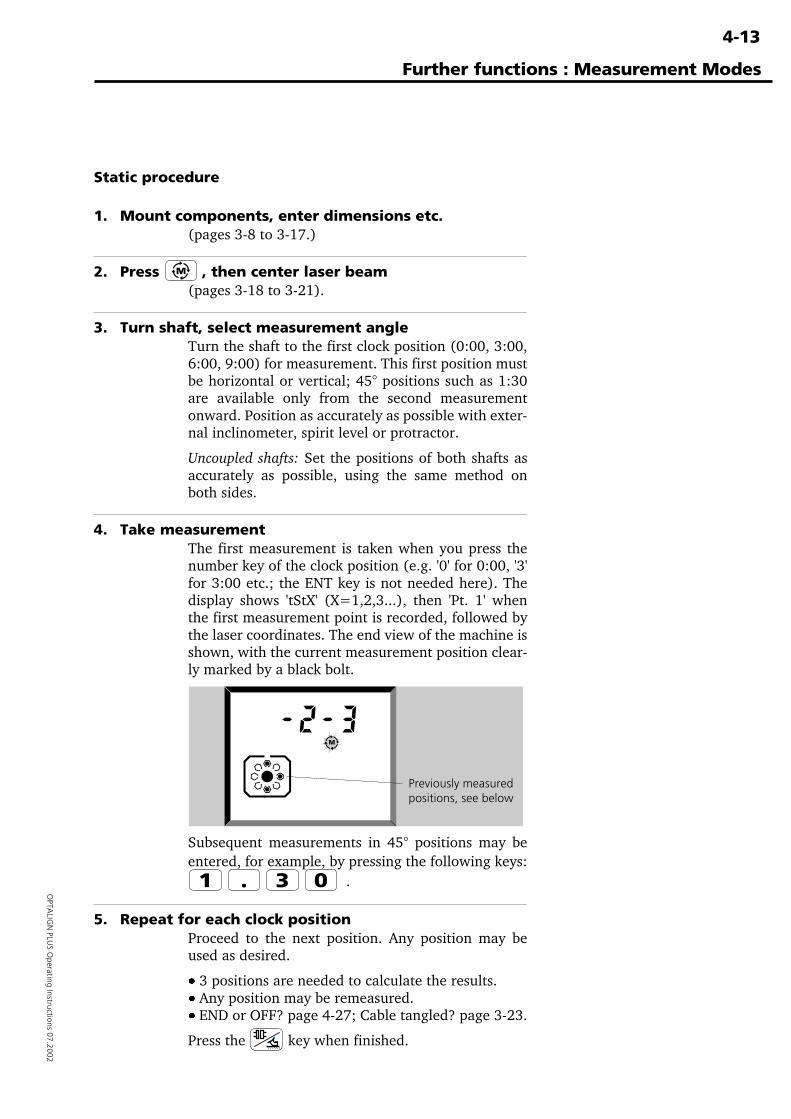
4-13
OPTA
LIGN
PLUS O
perating Instructions 07.2002
Static procedure
1. Mount components, enter dimensions etc.(pages 3-8 to 3-17.)
2. Press , then center laser beam(pages 3-18 to 3-21).
3. Turn shaft, select measurement angleTurn the shaft to the first clock position (0:00, 3:00,6:00, 9:00) for measurement. This first position mustbe horizontal or vertical; 45° positions such as 1:30are available only from the second measurementonward. Position as accurately as possible with exter-nal inclinometer, spirit level or protractor.
Uncoupled shafts: Set the positions of both shafts asaccurately as possible, using the same method onboth sides.
4. Take measurementThe first measurement is taken when you press thenumber key of the clock position (e.g. '0' for 0:00, '3'for 3:00 etc.; the ENT key is not needed here). Thedisplay shows 'tStX' (X=1,2,3...), then 'Pt. 1' whenthe first measurement point is recorded, followed bythe laser coordinates. The end view of the machine isshown, with the current measurement position clear-ly marked by a black bolt.
Subsequent measurements in 45° positions may beentered, for example, by pressing the following keys:
.
5. Repeat for each clock positionProceed to the next position. Any position may beused as desired.
·ÿ3 positions are needed to calculate the results.· Any position may be remeasured.· END or OFF? page 4-27; Cable tangled? page 3-23.
Press the key when finished.
Further functions : Measurement Modes
Previously measuredpositions, see below
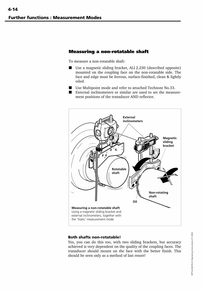
4-14
OPT
ALI
GN
PLU
S O
pera
ting
Inst
ruct
ions
07.
2002
Further functions : Measurement Modes
Measuring a non-rotatable shaft
To measure a non-rotatable shaft:
■ Use a magnetic sliding bracket, ALI 2.230 (described opposite)mounted on the coupling face on the non-rotatable side. Theface and edge must be ferrous, surface-finished, clean & lightlyoiled.
■ Use Multipoint mode and refer to attached Technote No.33.■ External inclinometers or similar are used to set the measure-
ment positions of the transducer AND reflector.
Both shafts non-rotatable!Yes, you can do this too, with two sliding brackets, but accuracyachieved is very dependent on the quality of the coupling faces. Thetransducer should mount on the face with the better finish. Thisshould be seen only as a method of last resort!
Measuring a non-rotatable shaftUsing a magnetic sliding bracket andexternal inclinometers, together withthe 'Static' measurement mode
Non-rotatingshaft
Rotatableshaft
Oil
Magneticslidingbracket
Externalinclinometers
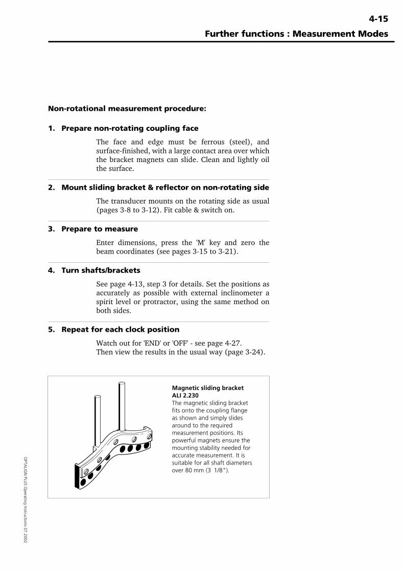
4-15
OPTA
LIGN
PLUS O
perating Instructions 07.2002
Further functions : Measurement Modes
Non-rotational measurement procedure:
1. Prepare non-rotating coupling face
The face and edge must be ferrous (steel), andsurface-finished, with a large contact area over whichthe bracket magnets can slide. Clean and lightly oilthe surface.
2. Mount sliding bracket & reflector on non-rotating side
The transducer mounts on the rotating side as usual(pages 3-8 to 3-12). Fit cable & switch on.
3. Prepare to measure
Enter dimensions, press the 'M' key and zero thebeam coordinates (see pages 3-15 to 3-21).
4. Turn shafts/brackets
See page 4-13, step 3 for details. Set the positions asaccurately as possible with external inclinometer aspirit level or protractor, using the same method onboth sides.
5. Repeat for each clock position
Watch out for 'END' or 'OFF' - see page 4-27.Then view the results in the usual way (page 3-24).
Magnetic sliding bracketALI 2.230The magnetic sliding bracketfits onto the coupling flangeas shown and simply slidesaround to the requiredmeasurement positions. Itspowerful magnets ensure themounting stability needed foraccurate measurement. It issuitable for all shaft diametersover 80 mm (3 1/8").
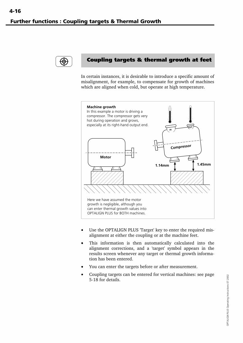
4-16
OPT
ALI
GN
PLU
S O
pera
ting
Inst
ruct
ions
07.
2002
Further functions : Coupling targets & Thermal Growth
Coupling targets & thermal growth at feet
In certain instances, it is desirable to introduce a specific amount ofmisalignment, for example, to compensate for growth of machineswhich are aligned when cold, but operate at high temperature.
· Use the OPTALIGN PLUS 'Target' key to enter the required mis-alignment at either the coupling or at the machine feet.
· This information is then automatically calculated into thealignment corrections, and a 'target' symbol appears in theresults screen whenever any target or thermal growth informa-tion has been entered.
· You can enter the targets before or after measurement.
· Coupling targets can be entered for vertical machines: see page5-18 for details.
Machine growthIn this example a motor is driving acompressor. The compressor gets veryhot during operation and grows,especially at its right-hand output end.
Here we have assumed the motorgrowth is negligible, although youcan enter thermal growth values intoOPTALIGN PLUS for BOTH machines.
Motor
Compressor
IN OUT
1.14mm 1.45mm
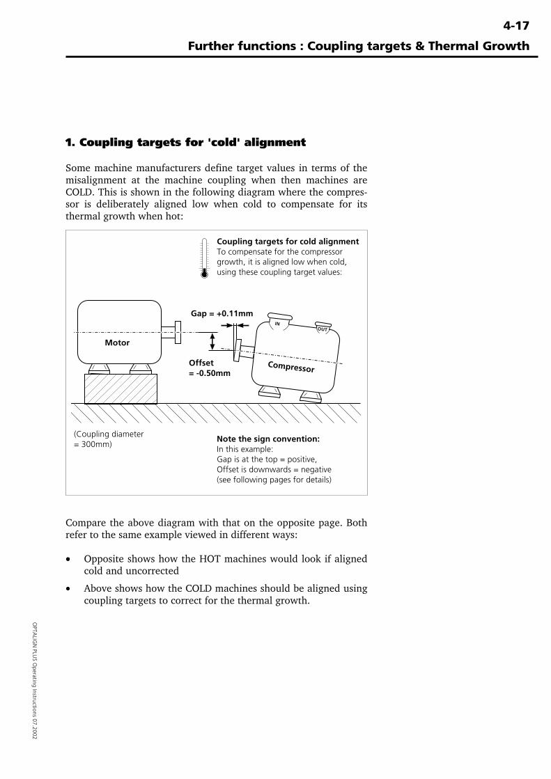
4-17
OPTA
LIGN
PLUS O
perating Instructions 07.2002
1. Coupling targets for 'cold' alignment
Some machine manufacturers define target values in terms of themisalignment at the machine coupling when then machines areCOLD. This is shown in the following diagram where the compres-sor is deliberately aligned low when cold to compensate for itsthermal growth when hot:
Compare the above diagram with that on the opposite page. Bothrefer to the same example viewed in different ways:
· Opposite shows how the HOT machines would look if alignedcold and uncorrected
· Above shows how the COLD machines should be aligned usingcoupling targets to correct for the thermal growth.
Further functions : Coupling targets & Thermal Growth
Gap = +0.11mm
Offset= -0.50mm
Coupling targets for cold alignmentTo compensate for the compressorgrowth, it is aligned low when cold,using these coupling target values:
Note the sign convention:In this example:Gap is at the top = positive,Offset is downwards = negative(see following pages for details)
Motor
Compressor
IN OUT
(Coupling diameter= 300mm)
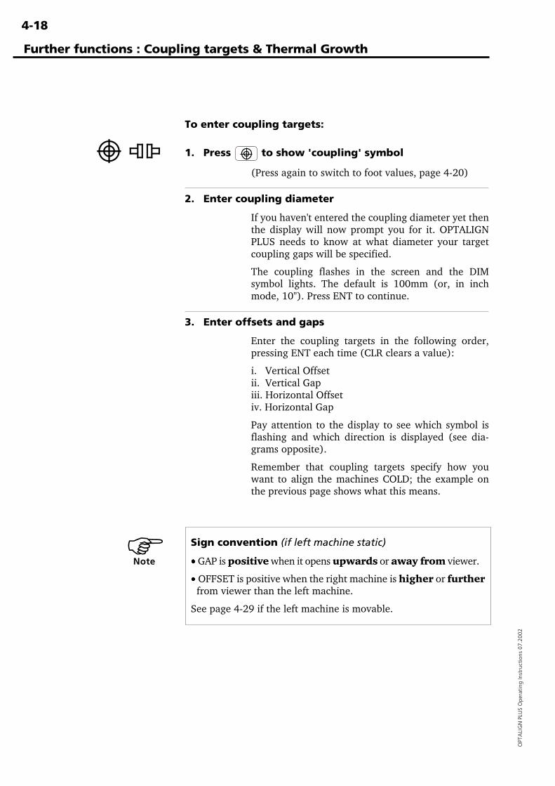
4-18
OPT
ALI
GN
PLU
S O
pera
ting
Inst
ruct
ions
07.
2002
To enter coupling targets:
1. Press to show 'coupling' symbol
(Press again to switch to foot values, page 4-20)
2. Enter coupling diameter
If you haven't entered the coupling diameter yet thenthe display will now prompt you for it. OPTALIGNPLUS needs to know at what diameter your targetcoupling gaps will be specified.
The coupling flashes in the screen and the DIMsymbol lights. The default is 100mm (or, in inchmode, 10"). Press ENT to continue.
3. Enter offsets and gaps
Enter the coupling targets in the following order,pressing ENT each time (CLR clears a value):
i. Vertical Offsetii. Vertical Gapiii. Horizontal Offsetiv. Horizontal Gap
Pay attention to the display to see which symbol isflashing and which direction is displayed (see dia-grams opposite).
Remember that coupling targets specify how youwant to align the machines COLD; the example onthe previous page shows what this means.
Further functions : Coupling targets & Thermal Growth
Sign convention (if left machine static)
· GAP is positive when it opens upwards or away from viewer.
· OFFSET is positive when the right machine is higher or further from viewer than the left machine.
See page 4-29 if the left machine is movable.
�Note
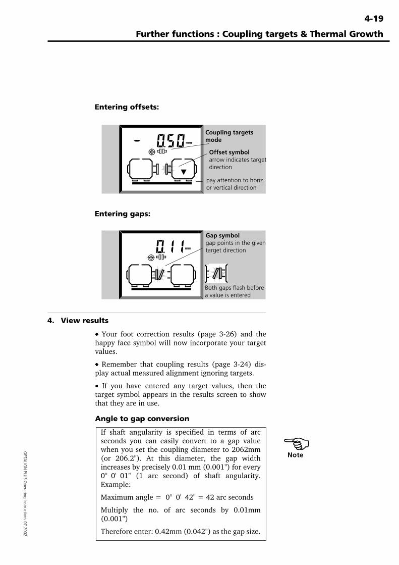
4-19
OPTA
LIGN
PLUS O
perating Instructions 07.2002
Entering offsets:
Entering gaps:
4. View results
· Your foot correction results (page 3-26) and thehappy face symbol will now incorporate your targetvalues.
· Remember that coupling results (page 3-24) dis-play actual measured alignment ignoring targets.
· If you have entered any target values, then thetarget symbol appears in the results screen to showthat they are in use.
Angle to gap conversion
If shaft angularity is specified in terms of arcseconds you can easily convert to a gap valuewhen you set the coupling diameter to 2062mm(or 206.2"). At this diameter, the gap widthincreases by precisely 0.01 mm (0.001") for every0° 0' 01" (1 arc second) of shaft angularity.Example:
Maximum angle = 0° 0' 42" = 42 arc seconds
Multiply the no. of arc seconds by 0.01mm(0.001")
Therefore enter: 0.42mm (0.042") as the gap size.
Further functions : Coupling targets & Thermal Growth
�Note
Coupling targetsmode
Offset symbolarrow indicates targetdirection
pay attention to horiz.or vertical direction
Gap symbolgap points in the giventarget direction
Both gaps flash beforea value is entered
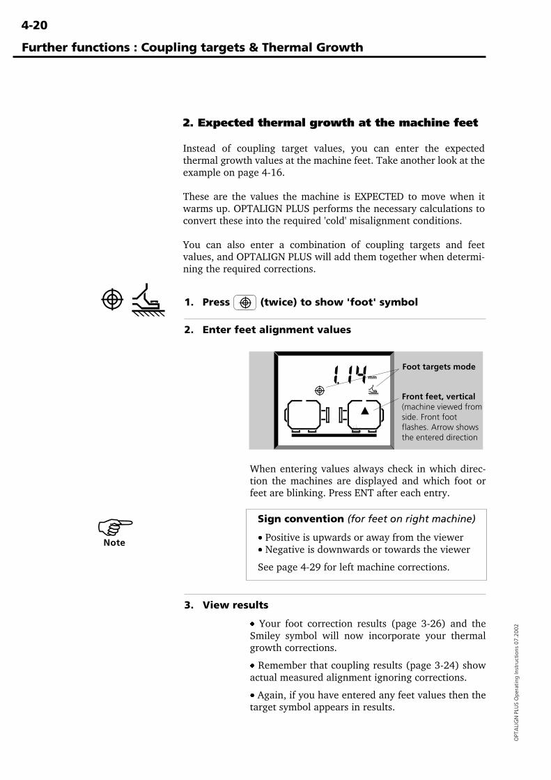
4-20
OPT
ALI
GN
PLU
S O
pera
ting
Inst
ruct
ions
07.
2002
1. Press (twice) to show 'foot' symbol
2. Enter feet alignment values
When entering values always check in which direc-tion the machines are displayed and which foot orfeet are blinking. Press ENT after each entry.
Sign convention (for feet on right machine)
· Positive is upwards or away from the viewer· Negative is downwards or towards the viewer
See page 4-29 for left machine corrections.
3. View results
· Your foot correction results (page 3-26) and theSmiley symbol will now incorporate your thermalgrowth corrections.
· Remember that coupling results (page 3-24) showactual measured alignment ignoring corrections.
· Again, if you have entered any feet values then thetarget symbol appears in results.
Further functions : Coupling targets & Thermal Growth
Foot targets mode
Front feet, vertical(machine viewed fromside. Front footflashes. Arrow showsthe entered direction
2. Expected thermal growth at the machine feet
Instead of coupling target values, you can enter the expectedthermal growth values at the machine feet. Take another look at theexample on page 4-16.
These are the values the machine is EXPECTED to move when itwarms up. OPTALIGN PLUS performs the necessary calculations toconvert these into the required 'cold' misalignment conditions.
You can also enter a combination of coupling targets and feetvalues, and OPTALIGN PLUS will add them together when determi-ning the required corrections.
�Note
4-21
OPTA
LIGN
PLUS O
perating Instructions 07.2002
Further functions : Coupling targets & Thermal Growth
3. Thermal growth for stationary machine
If, for example, the left machine cannot be moved during alignment,yet exhibits thermal growth, then proceed as follows:
1. Set the left machine to be moveable using F70
Use arrow keys to make a selection. See page 4-29.
2. Press DIM key, enter further required dimensions
OPTALIGN PLUS needs to know the distance fromthe transducer to the right feet of the left machine,and the distance between the left machine feet.
3. Press , enter targets for left machine
The display will prompt for the coupling targets andthermal growth values at the feet as described on theprevious pages. See 'sign convention' below.
4. Set left machine back to static with F70
5. Enter target values for the right machine if required
OPTALIGN PLUS will then take the target values forBOTH machines into account when calculating thealignment results for the moveable machine.
Universal sign conventionThe sign convention shown on the opposite page, and elsewherein this manual does not work when applied to the left machine.Instead we use a universal sign convention which applies to eithermachine:
i. The 'Machine To Be Moved' (MTBM) is the name we shall giveto the machine to which our target value will be applied.
ii. The target value will be for the MTBM RELATIVE TO thestationary machine.
The value is POSITIVE if the MTBM is HIGHER (or gap opensupwards).
The value is POSITIVE if the MTBM is further TOWARDS9 O'CLOCK (or gap opens toward 9 o'clock).[The clock is as viewed from the coupling toward the MTBM]
You will see that this convention also works for the right machineas we would expect!
�Note
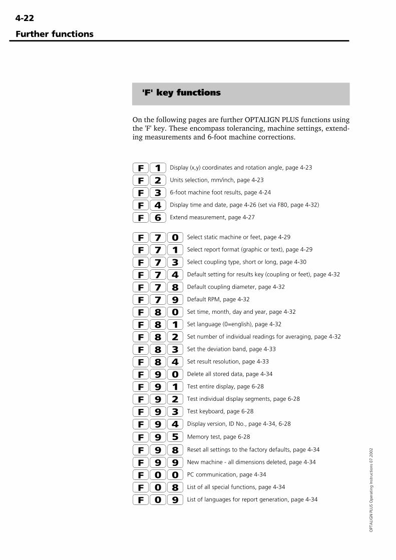
4-22
OPT
ALI
GN
PLU
S O
pera
ting
Inst
ruct
ions
07.
2002
Further functions
'F' key functions
On the following pages are further OPTALIGN PLUS functions usingthe 'F' key. These encompass tolerancing, machine settings, extend-ing measurements and 6-foot machine corrections.
Display (x,y) coordinates and rotation angle, page 4-23
Units selection, mm/inch, page 4-23
6-foot machine foot results, page 4-24
Display time and date, page 4-26 (set via F80, page 4-32)
Extend measurement, page 4-27
Select static machine or feet, page 4-29
Select report format (graphic or text), page 4-29
Select coupling type, short or long, page 4-30
Default setting for results key (coupling or feet), page 4-32
Default coupling diameter, page 4-32
Default RPM, page 4-32
Set time, month, day and year, page 4-32
Set language (0=english), page 4-32
Set number of individual readings for averaging, page 4-32
Set the deviation band, page 4-33
Set result resolution, page 4-33
Delete all stored data, page 4-34
Test entire display, page 6-28
Test individual display segments, page 6-28
Test keyboard, page 6-28
Display version, ID No., page 4-34, 6-28
Memory test, page 6-28
Reset all settings to the factory defaults, page 4-34
New machine - all dimensions deleted, page 4-34
PC communication, page 4-34
List of all special functions, page 4-34
List of languages for report generation, page 4-34
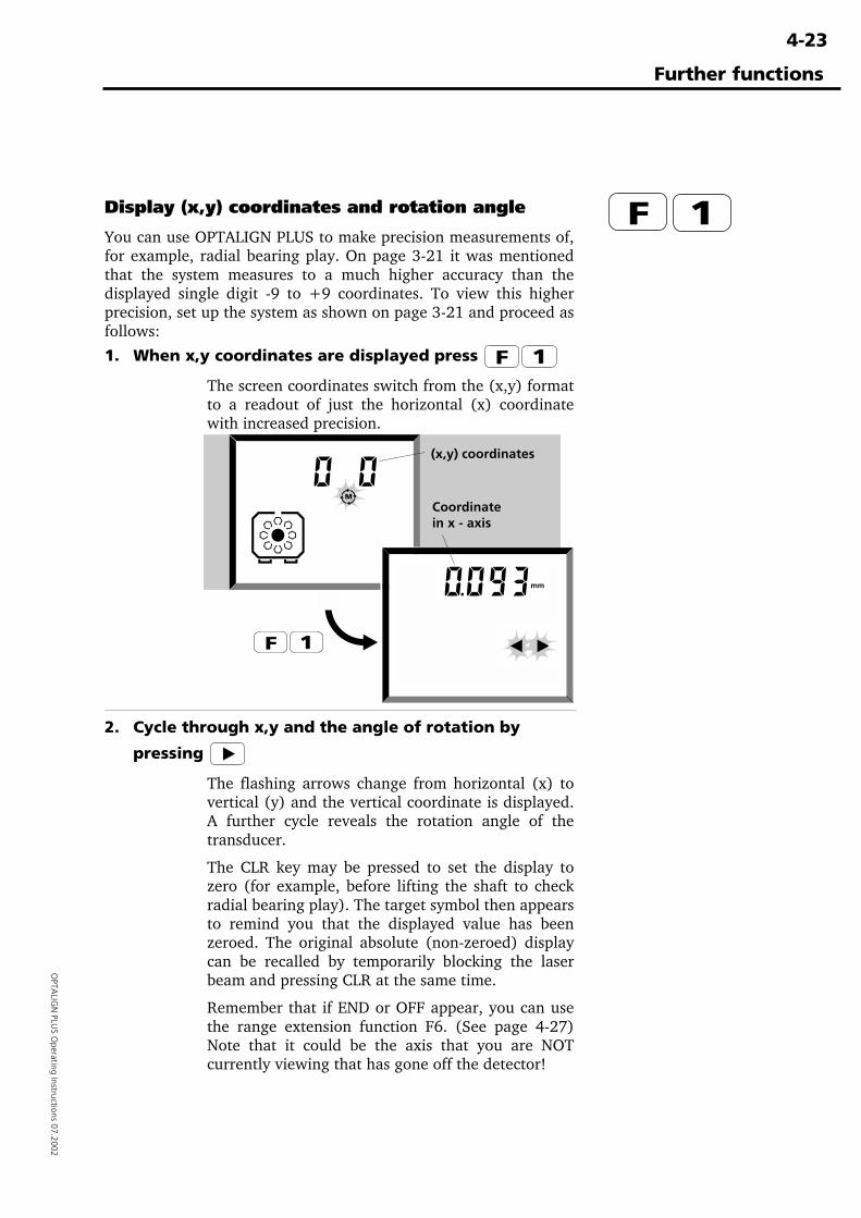
4-23
OPTA
LIGN
PLUS O
perating Instructions 07.2002
Display (x,y) coordinates and rotation angle
You can use OPTALIGN PLUS to make precision measurements of,for example, radial bearing play. On page 3-21 it was mentionedthat the system measures to a much higher accuracy than thedisplayed single digit -9 to +9 coordinates. To view this higherprecision, set up the system as shown on page 3-21 and proceed asfollows:
1. When x,y coordinates are displayed press
The screen coordinates switch from the (x,y) formatto a readout of just the horizontal (x) coordinatewith increased precision.
2. Cycle through x,y and the angle of rotation by
pressing
The flashing arrows change from horizontal (x) tovertical (y) and the vertical coordinate is displayed.A further cycle reveals the rotation angle of thetransducer.
The CLR key may be pressed to set the display tozero (for example, before lifting the shaft to checkradial bearing play). The target symbol then appearsto remind you that the displayed value has beenzeroed. The original absolute (non-zeroed) displaycan be recalled by temporarily blocking the laserbeam and pressing CLR at the same time.
Remember that if END or OFF appear, you can usethe range extension function F6. (See page 4-27)Note that it could be the axis that you are NOTcurrently viewing that has gone off the detector!
(x,y) coordinates
Coordinatein x - axis
Further functions
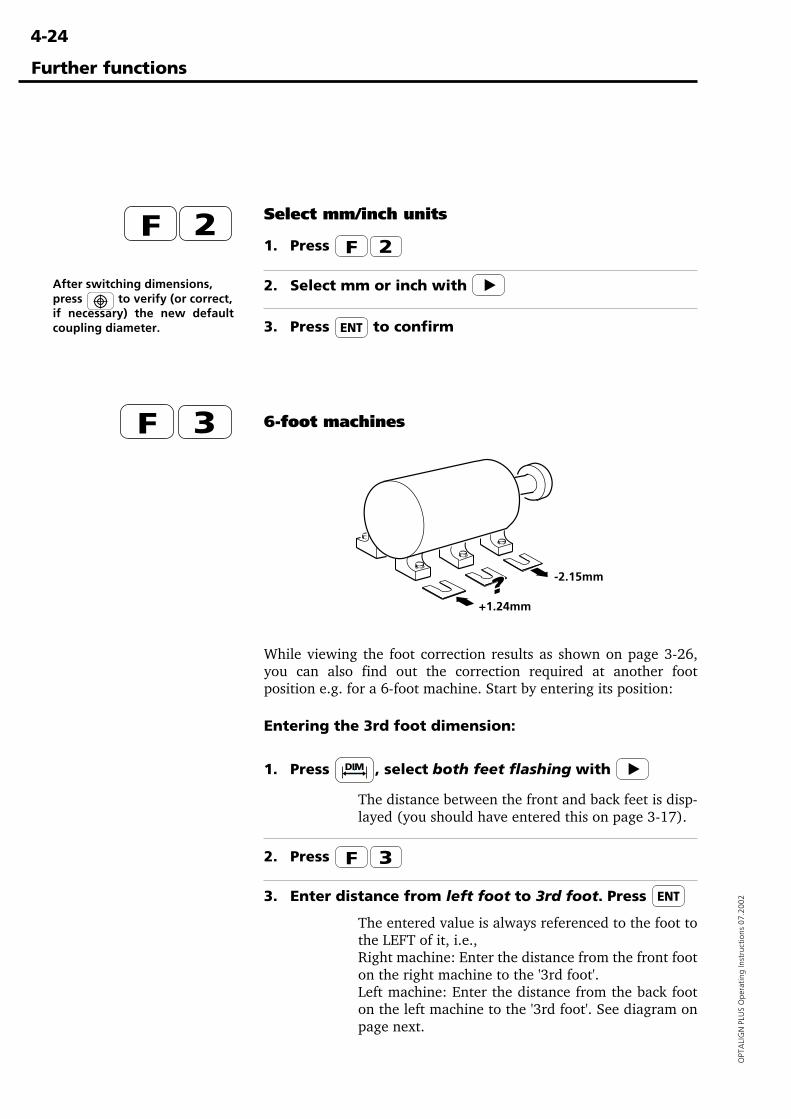
4-24
OPT
ALI
GN
PLU
S O
pera
ting
Inst
ruct
ions
07.
2002
Further functions
+1.24mm
Select mm/inch units
1. Press
2. Select mm or inch with
3. Press to confirm
After switching dimensions,press to verify (or correct,if necessary) the new defaultcoupling diameter.
6-foot machines
While viewing the foot correction results as shown on page 3-26,you can also find out the correction required at another footposition e.g. for a 6-foot machine. Start by entering its position:
Entering the 3rd foot dimension:
1. Press , select both feet flashing with
The distance between the front and back feet is disp-layed (you should have entered this on page 3-17).
2. Press
3. Enter distance from left foot to 3rd foot. Press
The entered value is always referenced to the foot tothe LEFT of it, i.e.,Right machine: Enter the distance from the front footon the right machine to the '3rd foot'.Left machine: Enter the distance from the back footon the left machine to the '3rd foot'. See diagram onpage next.
-2.15mm
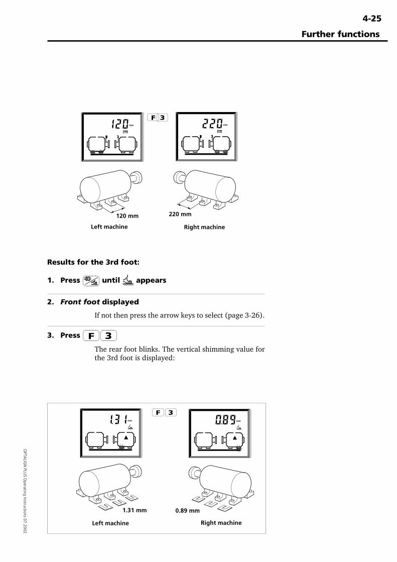
4-25
OPTA
LIGN
PLUS O
perating Instructions 07.2002
Further functions
1.31 mm 0.89 mm
Left machine Right machine
Results for the 3rd foot:
1. Press until appears
2. Front foot displayed
If not then press the arrow keys to select (page 3-26).
3. Press
The rear foot blinks. The vertical shimming value forthe 3rd foot is displayed:
120 mm 220 mm
Left machine Right machine
4-26
OPT
ALI
GN
PLU
S O
pera
ting
Inst
ruct
ions
07.
2002
Further functions
4. Press to cycle between vertical and horizontal
The display switches between the vertical shimming,and the horizontal move corrections for the 3rd foot.
5. Press to return to 4 feet
The values apply for the 4-feet machine again. PressF3 any time to show the 3rd foot corrections.
Display time and date
1. Press
The time, month+day, then year are displayed inturn. The date and time are stored with each file, andthese can be viewed on a PC using OPTALIGN PLUSExplorer, page 6-33. Use F80 to set the time/date(page 4-32).
2. Press to return to previous screen
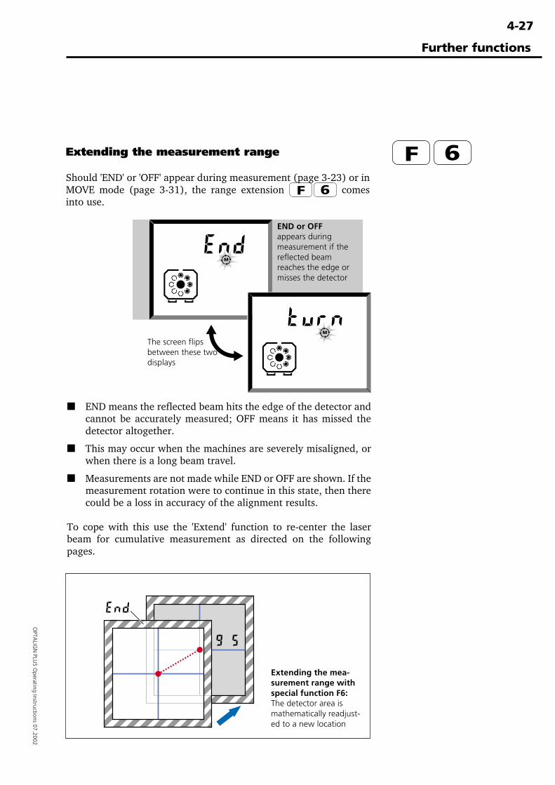
4-27
OPTA
LIGN
PLUS O
perating Instructions 07.2002
Further functions
Extending the measurement range
Should 'END' or 'OFF' appear during measurement (page 3-23) or inMOVE mode (page 3-31), the range extension comesinto use.
■ END means the reflected beam hits the edge of the detector andcannot be accurately measured; OFF means it has missed thedetector altogether.
■ This may occur when the machines are severely misaligned, orwhen there is a long beam travel.
■ Measurements are not made while END or OFF are shown. If themeasurement rotation were to continue in this state, then therecould be a loss in accuracy of the alignment results.
To cope with this use the 'Extend' function to re-center the laserbeam for cumulative measurement as directed on the followingpages.
The screen flipsbetween these twodisplays
Extending the mea-surement range withspecial function F6:The detector area ismathematically readjust-ed to a new location
END or OFFappears duringmeasurement if thereflected beamreaches the edge ormisses the detector
4-28
OPT
ALI
GN
PLU
S O
pera
ting
Inst
ruct
ions
07.
2002
Further functions
Extend procedure:
1. If END/OFF, turn back until coordinates reappear
Watch the display coordinates as the shafts areturned. If either value should reach ±9, stop rotatingthe shafts before 'END' or OFF' comes into thedisplay. If you go too far and 'END' or 'OFF' appears,rotate the shafts backwards just until the numbersreappear (in 'Sweep' mode, 'Set0' appears: thenproceed from Step 3 below). If coupling backlash ispresent: rotate backwards a bit further, then forwardjust until torsional play is taken up.
Once set, do not move the shafts from this position -keep them there all the way through to step 4 below!
2. Press
The transducer notes the exact beam coordinatesbefore re-centering occurs. The display briefly shows'tStX' (X=1,2,3), then 'Set0' alternates with the (x,y)coordinates as shown on page 3-21.
If F 6 is pressed when the laser beam lands outsidethe position detector ('END' or 'OFF'), then thetransducer cannot record the beam coordinates: afternine seconds, the system automatically switches backto measurement mode.
3. Rezero beam & press
Repeat the beam centering procedure so that thedisplay reads close to (0 0). The shafts must be heldsteady during reflector readjustment!
Once both coordinates are within ±1, the 'Set0'display changes to 'Entr', signifying that measure-ment can be resumed as normal.
Press ENT, and the amount of reflector readjustmentis registered and added to all subsequent measure-ments.
4. Proceed with measurement
Resume shaft rotation and measurement.
5. Repeated 'extends'
Repeat the 'Extend' as often as necessary. However, ifit must be repeated more than once or twice, it maybe better to take a measurement over a smaller angleand perform a rough alignment first.
�Note
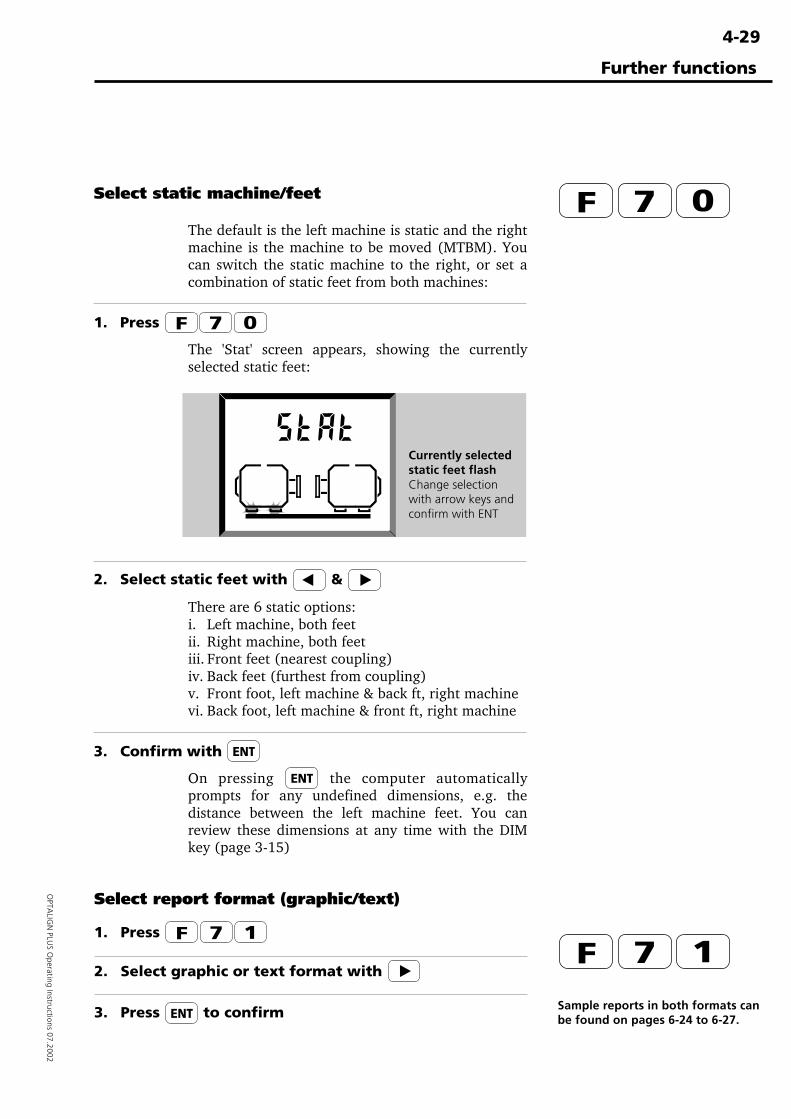
4-29
OPTA
LIGN
PLUS O
perating Instructions 07.2002
Further functions
Select static machine/feet
The default is the left machine is static and the rightmachine is the machine to be moved (MTBM). Youcan switch the static machine to the right, or set acombination of static feet from both machines:
1. Press
The 'Stat' screen appears, showing the currentlyselected static feet:
2. Select static feet with &
There are 6 static options:i. Left machine, both feetii. Right machine, both feetiii. Front feet (nearest coupling)iv. Back feet (furthest from coupling)v. Front foot, left machine & back ft, right machinevi. Back foot, left machine & front ft, right machine
3. Confirm with
On pressing the computer automaticallyprompts for any undefined dimensions, e.g. thedistance between the left machine feet. You canreview these dimensions at any time with the DIMkey (page 3-15)
Currently selectedstatic feet flashChange selectionwith arrow keys andconfirm with ENT
Select report format (graphic/text)
1. Press
2. Select graphic or text format with
3. Press to confirm Sample reports in both formats canbe found on pages 6-24 to 6-27.
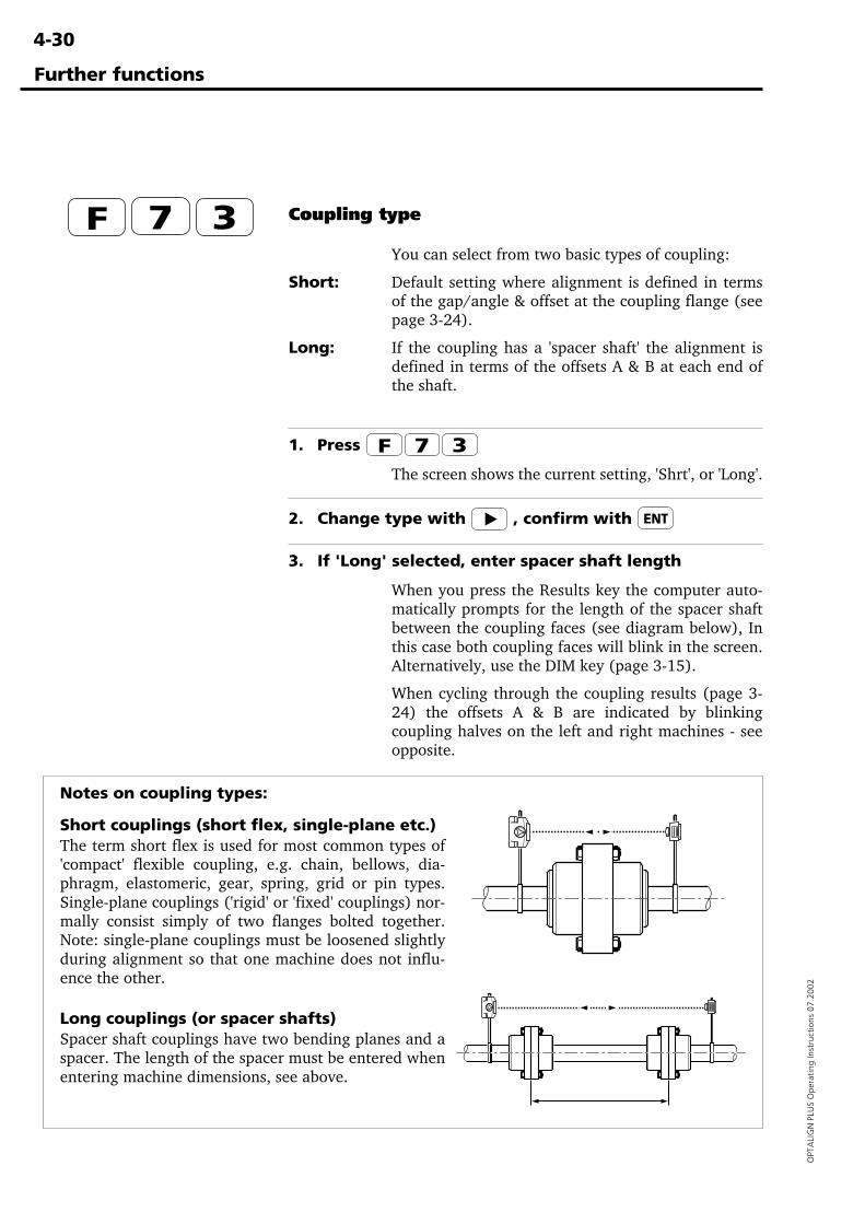
4-30
OPT
ALI
GN
PLU
S O
pera
ting
Inst
ruct
ions
07.
2002
Further functions
Coupling type
You can select from two basic types of coupling:
Short: Default setting where alignment is defined in termsof the gap/angle & offset at the coupling flange (seepage 3-24).
Long: If the coupling has a 'spacer shaft' the alignment isdefined in terms of the offsets A & B at each end ofthe shaft.
1. Press
The screen shows the current setting, 'Shrt', or 'Long'.
2. Change type with , confirm with
3. If 'Long' selected, enter spacer shaft length
When you press the Results key the computer auto-matically prompts for the length of the spacer shaftbetween the coupling faces (see diagram below), Inthis case both coupling faces will blink in the screen.Alternatively, use the DIM key (page 3-15).
When cycling through the coupling results (page 3-24) the offsets A & B are indicated by blinkingcoupling halves on the left and right machines - seeopposite.
Notes on coupling types:
Short couplings (short flex, single-plane etc.)The term short flex is used for most common types of'compact' flexible coupling, e.g. chain, bellows, dia-phragm, elastomeric, gear, spring, grid or pin types.Single-plane couplings ('rigid' or 'fixed' couplings) nor-mally consist simply of two flanges bolted together.Note: single-plane couplings must be loosened slightlyduring alignment so that one machine does not influ-ence the other.
Long couplings (or spacer shafts)Spacer shaft couplings have two bending planes and aspacer. The length of the spacer must be entered whenentering machine dimensions, see above.
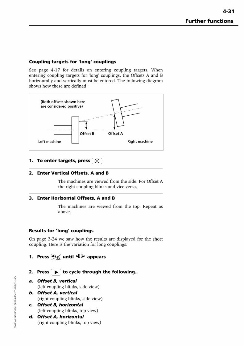
4-31
OPTA
LIGN
PLUS O
perating Instructions 07.2002
Further functions
Coupling targets for 'long' couplings
See page 4-17 for details on entering coupling targets. Whenentering coupling targets for 'long' couplings, the Offsets A and Bhorizontally and vertically must be entered. The following diagramshows how these are defined:
(Both offsets shown hereare considered positive)
1. To enter targets, press
2. Enter Vertical Offsets, A and B
The machines are viewed from the side. For Offset Athe right coupling blinks and vice versa.
3. Enter Horizontal Offsets, A and B
The machines are viewed from the top. Repeat asabove.
Results for 'long' couplings
On page 3-24 we saw how the results are displayed for the shortcoupling. Here is the variation for long couplings:
1. Press until appears
2. Press to cycle through the following..
a. Offset B, vertical(left coupling blinks, side view)
b. Offset A, vertical(right coupling blinks, side view)
c. Offset B, horizontal(left coupling blinks, top view)
d. Offset A, horizontal(right coupling blinks, top view)
Offset AOffset B
Left machine Right machine
4-32
OPT
ALI
GN
PLU
S O
pera
ting
Inst
ruct
ions
07.
2002
Setting defaults, time, resetting, etc
The following settings can be changed:
Coupling or Foot results, F 7 4
The factory default is Coupling results (see page 3-24). Press the arrow key to select between theCoupling or Foot symbols and confirm with ENT.Note that the order of the entered dimensions willchange if 'Foot' is selected (page 3-16).
Default coupling diameter, F 7 8
The factory default is 100mm (10"), but you canenter another value (e.g. 2062mm (206.2"), seepage 4-19). Confirm with ENT.
Default RPM shaft rotation, F 7 9
There is no default value given. Enter value andconfirm with ENT.
Time and date, F 8 0
1. Press F 8 0.
2. The time is shown with AM or PM. Enter thecorrect time in 12-hour clock format (use the key to specify AM or PM) and press ENT.
3. The month and day are shown. Enter a four digitnumber corresponding to the month and day, usingzeros to fill single digit values e.g. '0102' is 2ndJanuary. Press ENT
4. The year is shown. Enter the correct value andpress ENT. To exit press any one of the six functtionkeys above the digits.
F 8 1 : Select language
This applies to report printouts only. 0 = English(default), 1 = German, 2 = French. For otherlanguages available see printout F 0 9
Further functions
�Note
4-33
OPTA
LIGN
PLUS O
perating Instructions 07.2002
Further functions
F 8 2 : Set number of readings for averaging
This applies to 'point' measurement modes only (i.e.Multipoint and 0,3,6,9). It gives you a degree ofcontrol over measurement stability (and measure-ment duration) by specifying the number of individu-al readings to be averaged together into one compos-ite reading at each measurement point. F 8 2 lets youenter this number as a power of 2: 2² = 4 readings,2³ = 8, ..., 27 = 128 readings.
Measurement duration depends on the number ofindividual readings set for averaging; each readingtakes 50 ms, so for example, 32 readings would take(50 ms x 32) = 1.6 sec. per averaged measurement.
Note: Only half as many readings are takenduring soft foot and MOVE measurements inorder to speed up system reaction time
F 83 : Set the deviation band
It is often difficult to obtain measurement results inan enviroment where there is vibration. F 8 3 allowsthe stabilising of the coordinates while in "tSt" screenby setting the oscillation band to between 5µm and20µm. Default is 10µm.
F 84 : Set result resolution
The special function F84 enables us to set theresolution of results at either a low resolution (rS Lo)or a high resolution (rS Hi). Use or toselect desired resolution and confirm with the enterkey.
�Note
4-34
OPT
ALI
GN
PLU
S O
pera
ting
Inst
ruct
ions
07.
2002
F 9 0 : Delete all files and data
The message 'CLr?' appears. Press the CLR key toproceed or any other key apart from the number keysto cancel.
F 9 4 : Transducer sleep mode / ID display
When the special function F94 is selected, instrumentID No., firmware version and hardware versionappear consecutively on the screen. 'HArd 1' indicateshardware version 1 and this does not support thesleep mode. 'HArd 3' supports sleep mode. To be ableto utilise this function, firmware 1.18 or higher isrequired. If the processor inside the sensor is activat-ed but the laser is not yet firing and no key is pressedor laser activity initialised, the receiver LED is shutoff after a few seconds. The display will still be alivebut the transducer has entered the sleep mode.Pressing any key re-initializes the transducer immedi-ately.
F 98 : Reset to factory defaults
All changed defaults are reset to the factory settings.F99 : New machine
All current dimensions and measurements arecleared ready for the next job.
See also page 6-28 for various test functions.
Further functions
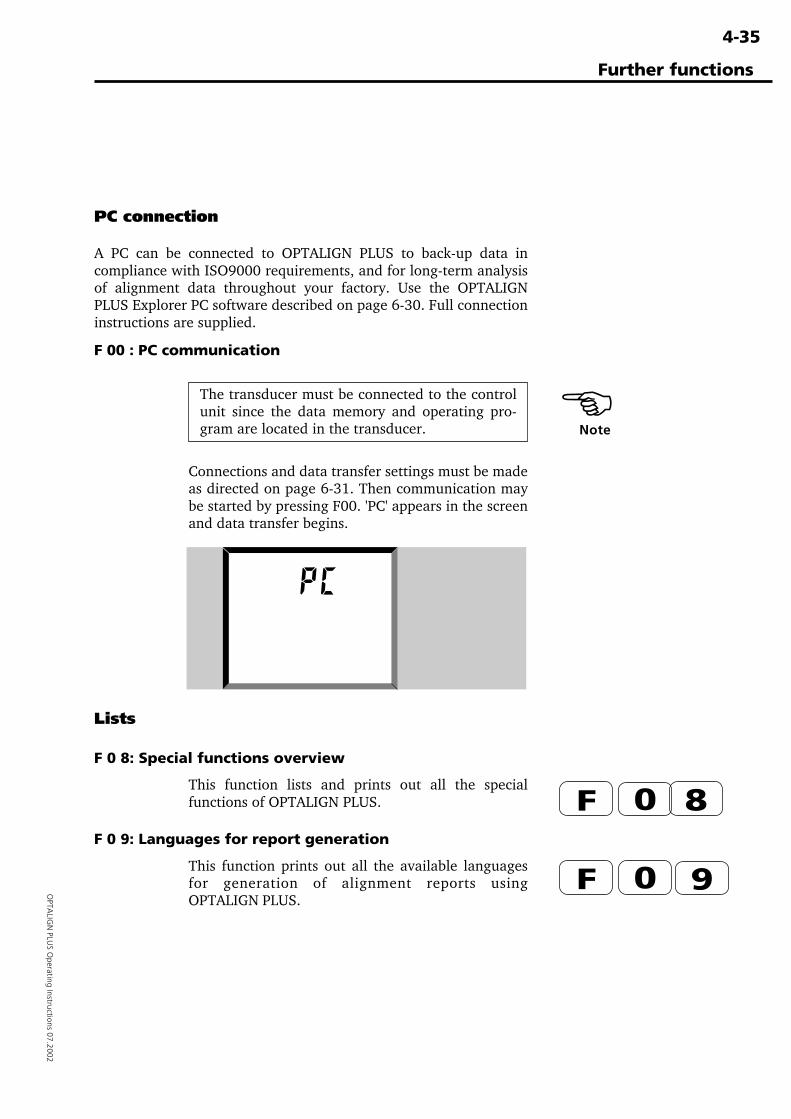
4-35
OPTA
LIGN
PLUS O
perating Instructions 07.2002
Lists
F 0 8: Special functions overview
This function lists and prints out all the specialfunctions of OPTALIGN PLUS.
F 0 9: Languages for report generation
This function prints out all the available languagesfor generation of alignment reports usingOPTALIGN PLUS.
PC connection
A PC can be connected to OPTALIGN PLUS to back-up data incompliance with ISO9000 requirements, and for long-term analysisof alignment data throughout your factory. Use the OPTALIGNPLUS Explorer PC software described on page 6-30. Full connectioninstructions are supplied.
F 00 : PC communication
The transducer must be connected to the controlunit since the data memory and operating pro-gram are located in the transducer.
Connections and data transfer settings must be madeas directed on page 6-31. Then communication maybe started by pressing F00. 'PC' appears in the screenand data transfer begins.
PC communicationin progress
�Note
Further functions
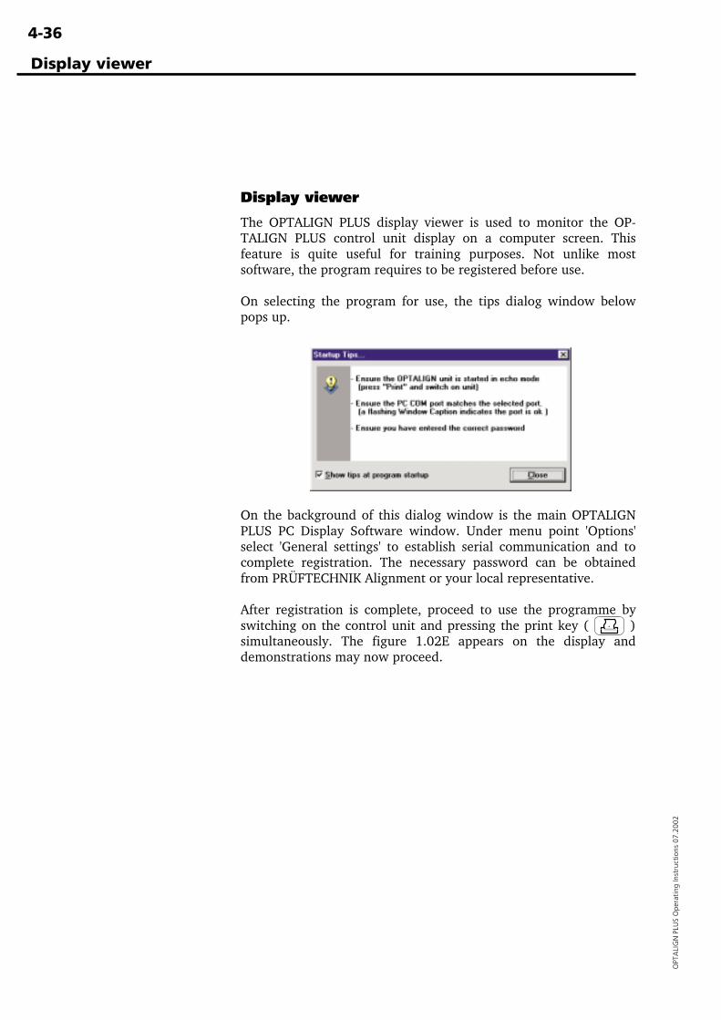
4-36
OPT
ALI
GN
PLU
S O
pera
ting
Inst
ruct
ions
07.
2002
Display viewer
The OPTALIGN PLUS display viewer is used to monitor the OP-TALIGN PLUS control unit display on a computer screen. Thisfeature is quite useful for training purposes. Not unlike mostsoftware, the program requires to be registered before use.
On selecting the program for use, the tips dialog window belowpops up.
On the background of this dialog window is the main OPTALIGNPLUS PC Display Software window. Under menu point 'Options'select 'General settings' to establish serial communication and tocomplete registration. The necessary password can be obtainedfrom PRÜFTECHNIK Alignment or your local representative.
After registration is complete, proceed to use the programme byswitching on the control unit and pressing the print key ( )simultaneously. The figure 1.02E appears on the display anddemonstrations may now proceed.
Display viewer
5-1
OPTA
LIGN
PLUS O
perating Instructions 07.2002
Chapter 5: Alignment of vertical machines
This chapter tells how OPTALIGN PLUS transforms alignment ofvertical machines from a major measurement challenge to a straight-forward and relatively simple task.
Chapter 1 Introduction .......................................1-1 to 1-12
Chapter 2 Description .........................................2-1 to 2-14
Chapter 3 Horizontal alignment ........................3-1 to 3-38
Chapter 4 Further functions ...............................4-1 to 4-36
Chapter 5: Alignment of vertical machines ..... 5-1 to 5-18Vertical machine alignment flow chart ....................................... 5-2Vertical machine alignment ........................................................ 5-4
1. Setup OPTALIGN PLUS components .................................... 5-52. Enter dimensions ................................................................. 5-73. Adjust laser beam .............................................................. 5-104. Measure ............................................................................. 5-115. Results ............................................................................... 5-126. Align machine .................................................................... 5-146a. Shimming at the flange .................................................. 5-156b. Remeasure ..................................................................... 5-156c. Move horizontally .......................................................... 5-166d. Final check ..................................................................... 5-17
Coupling targets for vertical machines ..................................... 5-18
Chapter 6 Appendix ............................................6-1 to 6-50
Vertical machine alignment
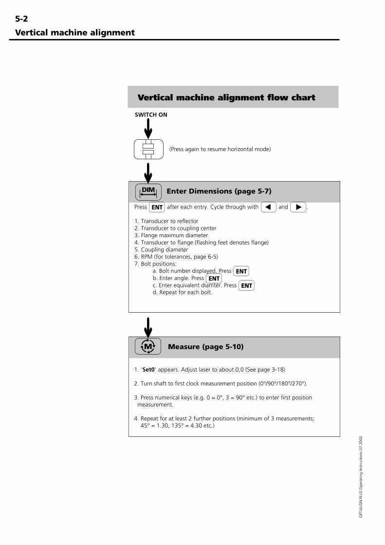
5-2
OPT
ALI
GN
PLU
S O
pera
ting
Inst
ruct
ions
07.
2002
Vertical machine alignment
Vertical machine alignment flow chart
SWITCH ON
Enter Dimensions (page 5-7)
Press after each entry. Cycle through with and .
1. Transducer to reflector2. Transducer to coupling center3. Flange maximum diameter4. Transducer to flange (flashing feet denotes flange)5. Coupling diameter6. RPM (for tolerances, page 6-5)7. Bolt positions:
a. Bolt number displayed. Press b. Enter angle. Press c. Enter equivalent diamter. Press d. Repeat for each bolt.
(Press again to resume horizontal mode)
➜➜
➜
Measure (page 5-10)
1. 'Set0' appears. Adjust laser to about 0,0 (See page 3-18)
2. Turn shaft to first clock measurement position (0°/90°/180°/270°).
3. Press numerical keys (e.g. 0 = 0°, 3 = 90° etc.) to enter first position measurement.
4. Repeat for at least 2 further positions (minimum of 3 measurements; 45° = 1.30, 135° = 4.30 etc.)
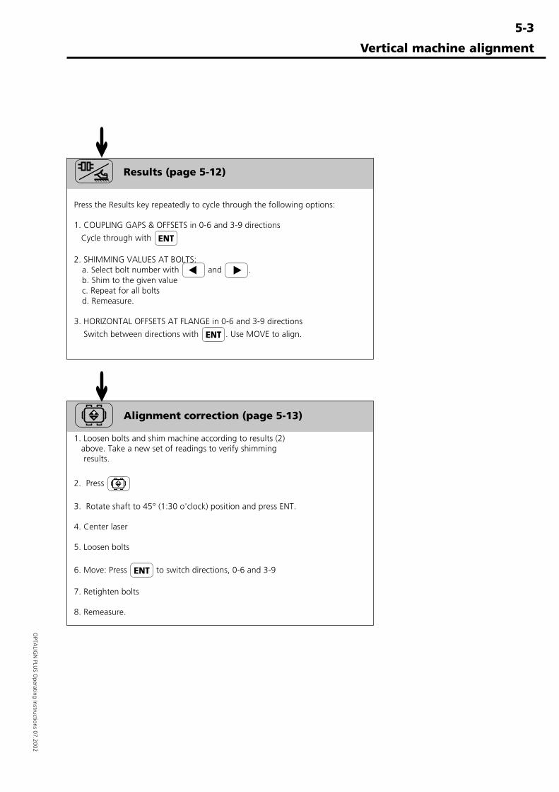
5-3
OPTA
LIGN
PLUS O
perating Instructions 07.2002
Vertical machine alignment
Results (page 5-12)
Press the Results key repeatedly to cycle through the following options:
1. COUPLING GAPS & OFFSETS in 0-6 and 3-9 directions
Cycle through with
2. SHIMMING VALUES AT BOLTS:a. Select bolt number with and .b. Shim to the given valuec. Repeat for all boltsd. Remeasure.
3. HORIZONTAL OFFSETS AT FLANGE in 0-6 and 3-9 directions
Switch between directions with . Use MOVE to align.
Alignment correction (page 5-13)
1. Loosen bolts and shim machine according to results (2) above. Take a new set of readings to verify shimming results.
2. Press
3. Rotate shaft to 45° (1:30 o'clock) position and press ENT.
4. Center laser
5. Loosen bolts
6. Move: Press to switch directions, 0-6 and 3-9
7. Retighten bolts
8. Remeasure.
➜➜
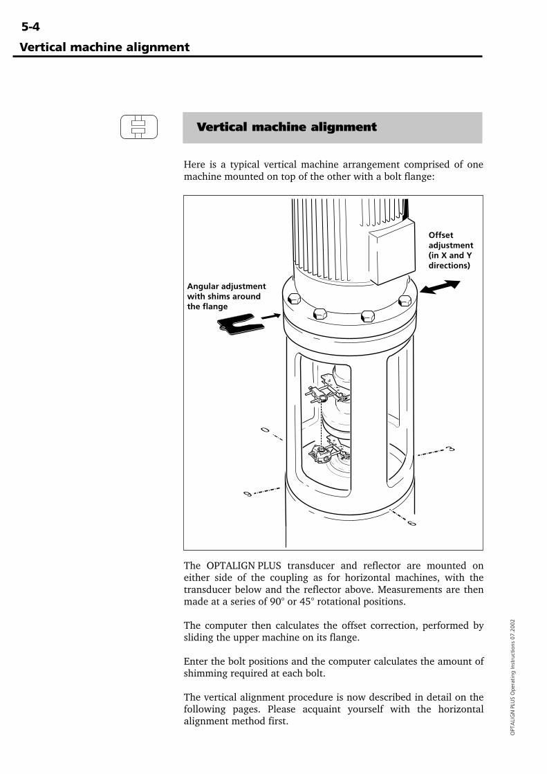
5-4
OPT
ALI
GN
PLU
S O
pera
ting
Inst
ruct
ions
07.
2002
Vertical machine alignment
Here is a typical vertical machine arrangement comprised of onemachine mounted on top of the other with a bolt flange:
The OPTALIGN PLUS transducer and reflector are mounted oneither side of the coupling as for horizontal machines, with thetransducer below and the reflector above. Measurements are thenmade at a series of 90° or 45° rotational positions.
The computer then calculates the offset correction, performed bysliding the upper machine on its flange.
Enter the bolt positions and the computer calculates the amount ofshimming required at each bolt.
The vertical alignment procedure is now described in detail on thefollowing pages. Please acquaint yourself with the horizontalalignment method first.
Vertical machine alignment
Offsetadjustment(in X and Ydirections)
Angular adjustmentwith shims aroundthe flange
9
3
0
6
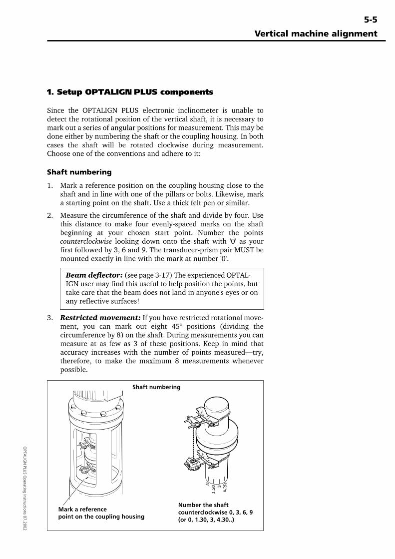
5-5
OPTA
LIGN
PLUS O
perating Instructions 07.2002
Vertical machine alignment
1. Setup OPTALIGN PLUS components
Since the OPTALIGN PLUS electronic inclinometer is unable todetect the rotational position of the vertical shaft, it is necessary tomark out a series of angular positions for measurement. This may bedone either by numbering the shaft or the coupling housing. In bothcases the shaft will be rotated clockwise during measurement.Choose one of the conventions and adhere to it:
Shaft numbering
1. Mark a reference position on the coupling housing close to theshaft and in line with one of the pillars or bolts. Likewise, marka starting point on the shaft. Use a thick felt pen or similar.
2. Measure the circumference of the shaft and divide by four. Usethis distance to make four evenly-spaced marks on the shaftbeginning at your chosen start point. Number the pointscounterclockwise looking down onto the shaft with '0' as yourfirst followed by 3, 6 and 9. The transducer-prism pair MUST bemounted exactly in line with the mark at number '0'.
Beam deflector: (see page 3-17) The experienced OPTAL-IGN user may find this useful to help position the points, buttake care that the beam does not land in anyone's eyes or onany reflective surfaces!
3. Restricted movement: If you have restricted rotational move-ment, you can mark out eight 45° positions (dividing thecircumference by 8) on the shaft. During measurements you canmeasure at as few as 3 of these positions. Keep in mind thataccuracy increases with the number of points measured—try,therefore, to make the maximum 8 measurements wheneverpossible.
Shaft numbering
Mark a referencepoint on the coupling housing
Number the shaftcounterclockwise 0, 3, 6, 9(or 0, 1.30, 3, 4.30..)
01.
30 34.
30
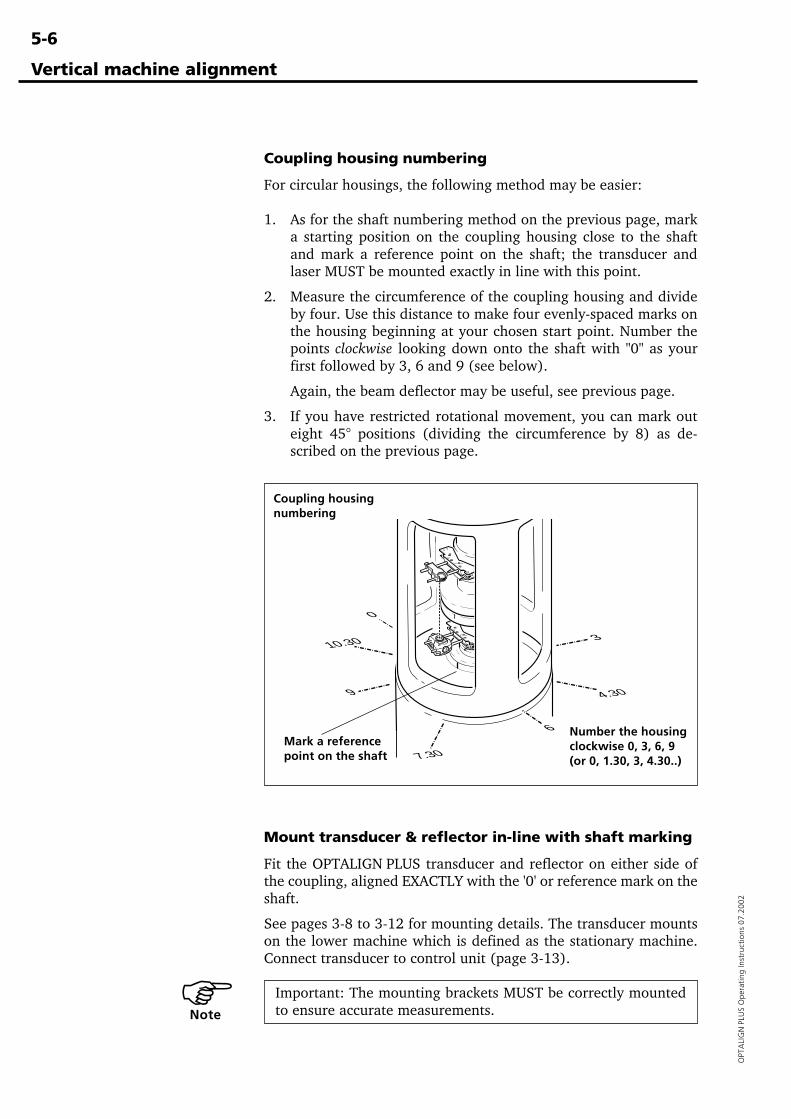
5-6
OPT
ALI
GN
PLU
S O
pera
ting
Inst
ruct
ions
07.
2002
Mount transducer & reflector in-line with shaft marking
Fit the OPTALIGN PLUS transducer and reflector on either side ofthe coupling, aligned EXACTLY with the '0' or reference mark on theshaft.
See pages 3-8 to 3-12 for mounting details. The transducer mountson the lower machine which is defined as the stationary machine.Connect transducer to control unit (page 3-13).
Important: The mounting brackets MUST be correctly mountedto ensure accurate measurements.
Vertical machine alignment
Coupling housing numbering
For circular housings, the following method may be easier:
1. As for the shaft numbering method on the previous page, marka starting position on the coupling housing close to the shaftand mark a reference point on the shaft; the transducer andlaser MUST be mounted exactly in line with this point.
2. Measure the circumference of the coupling housing and divideby four. Use this distance to make four evenly-spaced marks onthe housing beginning at your chosen start point. Number thepoints clockwise looking down onto the shaft with "0" as yourfirst followed by 3, 6 and 9 (see below).
Again, the beam deflector may be useful, see previous page.
3. If you have restricted rotational movement, you can mark outeight 45° positions (dividing the circumference by 8) as de-scribed on the previous page.
�Note
9
3
0
6
10.30
7.30
4.30
Coupling housingnumbering
Mark a referencepoint on the shaft
Number the housingclockwise 0, 3, 6, 9(or 0, 1.30, 3, 4.30..)
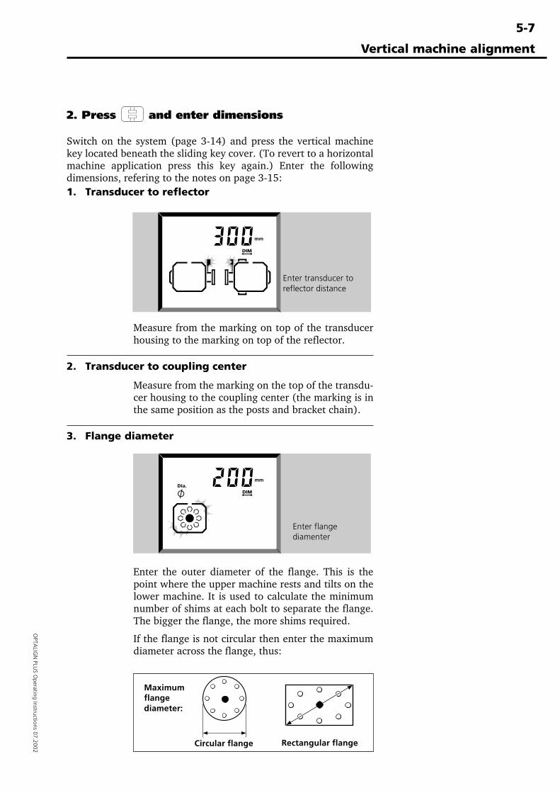
5-7
OPTA
LIGN
PLUS O
perating Instructions 07.2002
Vertical machine alignment
2. Press and enter dimensions
Switch on the system (page 3-14) and press the vertical machinekey located beneath the sliding key cover. (To revert to a horizontalmachine application press this key again.) Enter the followingdimensions, refering to the notes on page 3-15:1. Transducer to reflector
Measure from the marking on top of the transducerhousing to the marking on top of the reflector.
2. Transducer to coupling center
Measure from the marking on the top of the transdu-cer housing to the coupling center (the marking is inthe same position as the posts and bracket chain).
3. Flange diameter
Enter the outer diameter of the flange. This is thepoint where the upper machine rests and tilts on thelower machine. It is used to calculate the minimumnumber of shims at each bolt to separate the flange.The bigger the flange, the more shims required.
If the flange is not circular then enter the maximumdiameter across the flange, thus:
Enter transducer toreflector distance
Enter flangediamenter
Maximumflangediameter:
Circular flange Rectangular flange
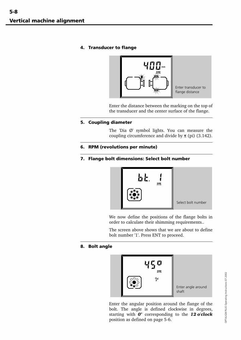
5-8
OPT
ALI
GN
PLU
S O
pera
ting
Inst
ruct
ions
07.
2002
4. Transducer to flange
Enter the distance between the marking on the top ofthe transducer and the center surface of the flange.
5. Coupling diameter
The 'Dia Ø' symbol lights. You can measure thecoupling circumference and divide by p (pi) (3.142).
6. RPM (revolutions per minute)
7. Flange bolt dimensions: Select bolt number
We now define the positions of the flange bolts inorder to calculate their shimming requirements..
The screen above shows that we are about to definebolt number '1'. Press ENT to proceed.
8. Bolt angle
Enter the angular position around the flange of thebolt. The angle is defined clockwise in degrees,starting with 0° corresponding to the 12 o'clockposition as defined on page 5-6.
Vertical machine alignment
Enter angle aroundshaft
Enter transducer toflange distance
Select bolt number
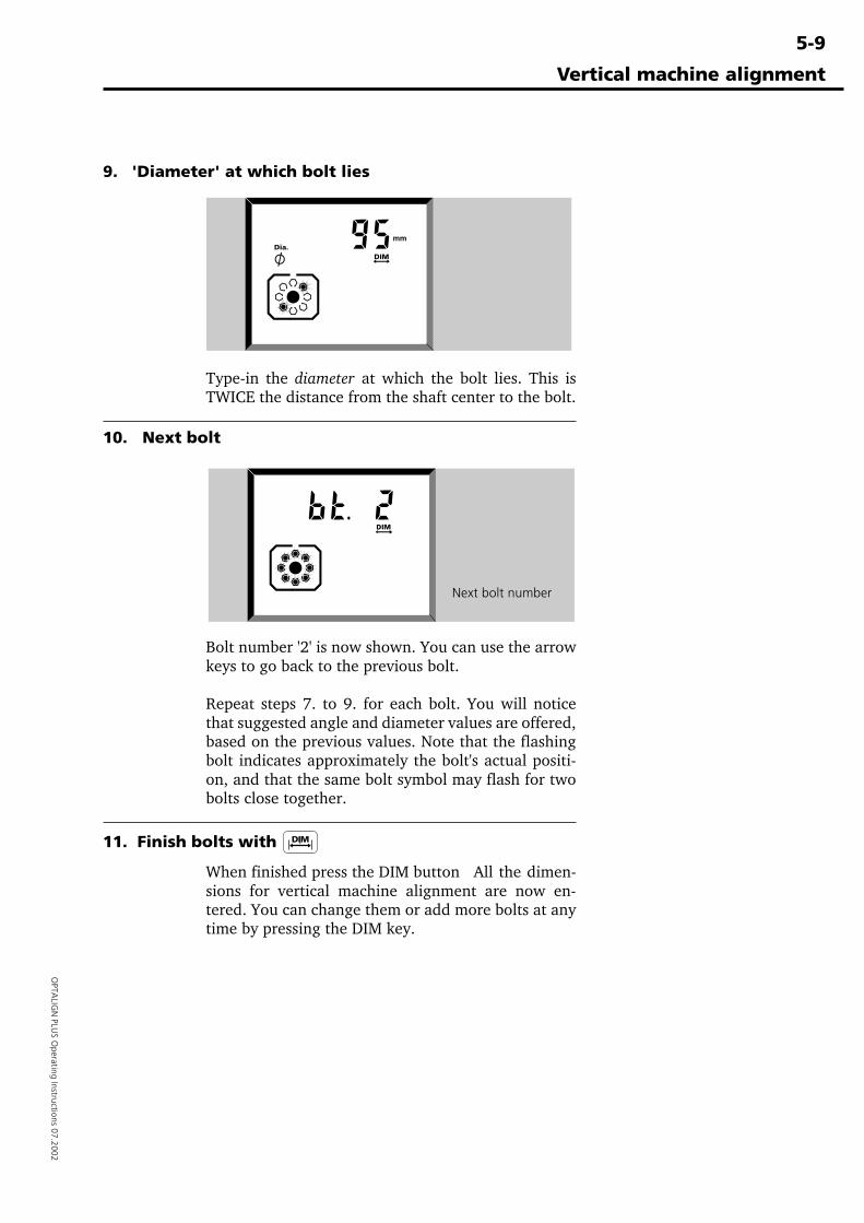
5-9
OPTA
LIGN
PLUS O
perating Instructions 07.2002
Vertical machine alignment
9. 'Diameter' at which bolt lies
Type-in the diameter at which the bolt lies. This isTWICE the distance from the shaft center to the bolt.
10. Next bolt
Bolt number '2' is now shown. You can use the arrowkeys to go back to the previous bolt.
Repeat steps 7. to 9. for each bolt. You will noticethat suggested angle and diameter values are offered,based on the previous values. Note that the flashingbolt indicates approximately the bolt's actual positi-on, and that the same bolt symbol may flash for twobolts close together.
11. Finish bolts with
When finished press the DIM button All the dimen-sions for vertical machine alignment are now en-tered. You can change them or add more bolts at anytime by pressing the DIM key.
Enter diameter atwhich bolt lies
Next bolt number
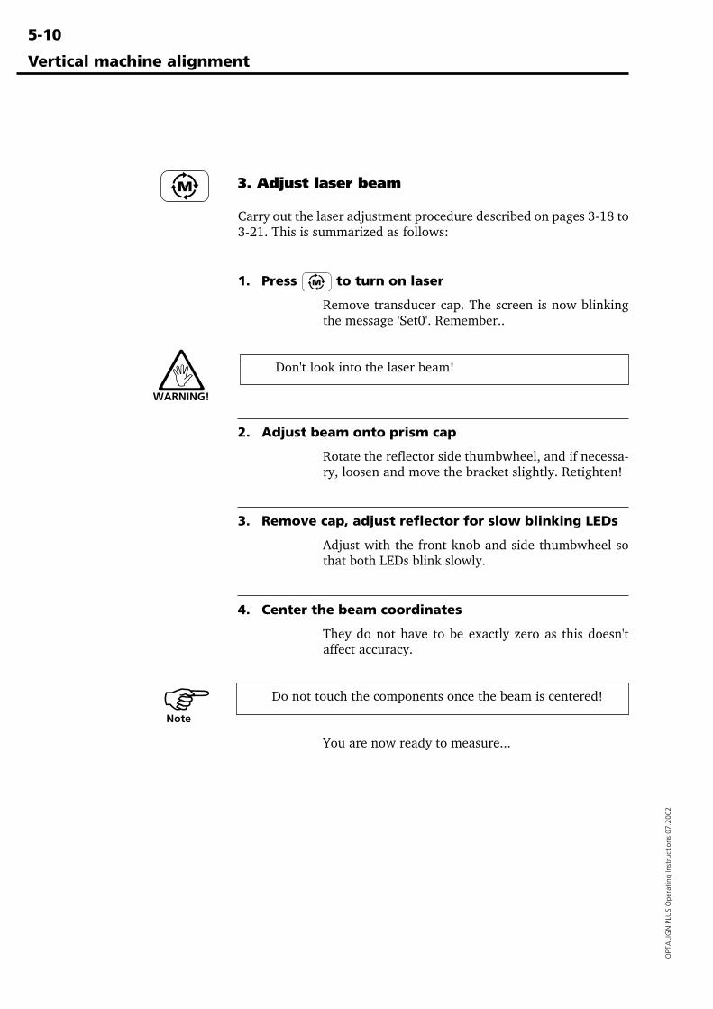
5-10
OPT
ALI
GN
PLU
S O
pera
ting
Inst
ruct
ions
07.
2002
3. Adjust laser beam
Carry out the laser adjustment procedure described on pages 3-18 to3-21. This is summarized as follows:
1. Press to turn on laser
Remove transducer cap. The screen is now blinkingthe message 'Set0'. Remember..
Don't look into the laser beam!
2. Adjust beam onto prism cap
Rotate the reflector side thumbwheel, and if necessa-ry, loosen and move the bracket slightly. Retighten!
3. Remove cap, adjust reflector for slow blinking LEDs
Adjust with the front knob and side thumbwheel sothat both LEDs blink slowly.
4. Center the beam coordinates
They do not have to be exactly zero as this doesn'taffect accuracy.
Do not touch the components once the beam is centered!
You are now ready to measure...
Vertical machine alignment
WARNING!
�Note
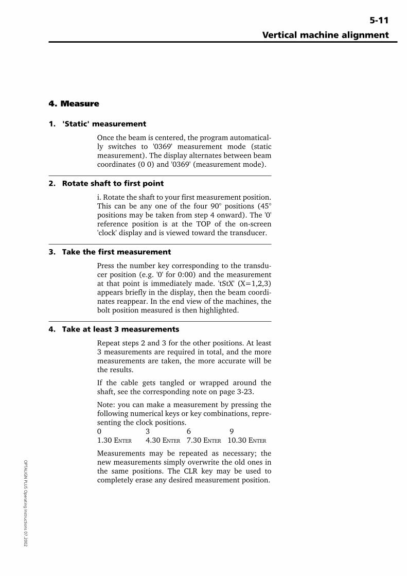
5-11
OPTA
LIGN
PLUS O
perating Instructions 07.2002
Vertical machine alignment
4. Measure
1. 'Static' measurement
Once the beam is centered, the program automatical-ly switches to '0369' measurement mode (staticmeasurement). The display alternates between beamcoordinates (0 0) and '0369' (measurement mode).
2. Rotate shaft to first point
i. Rotate the shaft to your first measurement position.This can be any one of the four 90° positions (45°positions may be taken from step 4 onward). The '0'reference position is at the TOP of the on-screen'clock' display and is viewed toward the transducer.
3. Take the first measurement
Press the number key corresponding to the transdu-cer position (e.g. '0' for 0:00) and the measurementat that point is immediately made. 'tStX' (X=1,2,3)appears briefly in the display, then the beam coordi-nates reappear. In the end view of the machines, thebolt position measured is then highlighted.
4. Take at least 3 measurements
Repeat steps 2 and 3 for the other positions. At least3 measurements are required in total, and the moremeasurements are taken, the more accurate will bethe results.
If the cable gets tangled or wrapped around theshaft, see the corresponding note on page 3-23.
Note: you can make a measurement by pressing thefollowing numerical keys or key combinations, repre-senting the clock positions.0 3 6 91.30 ENTER 4.30 ENTER 7.30 ENTER 10.30 ENTER
Measurements may be repeated as necessary; thenew measurements simply overwrite the old ones inthe same positions. The CLR key may be used tocompletely erase any desired measurement position.
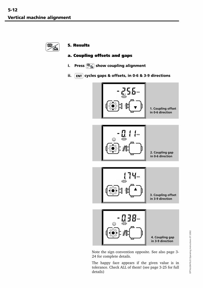
5-12
OPT
ALI
GN
PLU
S O
pera
ting
Inst
ruct
ions
07.
2002
5. Results
a. Coupling offsets and gaps
i. Press show coupling alignment
ii. cycles gaps & offsets, in 0-6 & 3-9 directions
Note the sign convention opposite. See also page 3-24 for complete details.
The happy face appears if the given value is intolerance. Check ALL of them! (see page 3-25 for fulldetails)
Vertical machine alignment
1. Coupling offsetin 0-6 direction
2. Coupling gapin 0-6 direction
3. Coupling offsetin 3-9 direction
4. Coupling gapin 3-9 direction
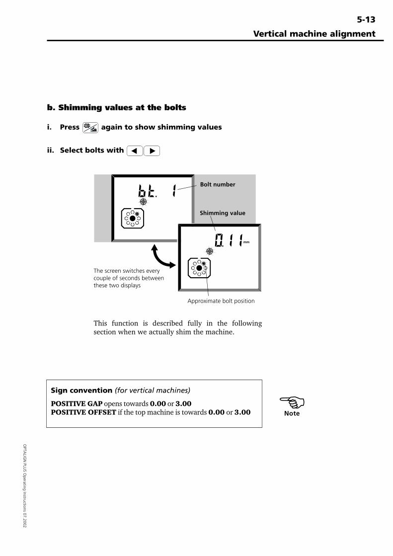
5-13
OPTA
LIGN
PLUS O
perating Instructions 07.2002
Vertical machine alignment
Sign convention (for vertical machines)
POSITIVE GAP opens towards 0.00 or 3.00POSITIVE OFFSET if the top machine is towards 0.00 or 3.00
b. Shimming values at the bolts
i. Press again to show shimming values
ii. Select bolts with
The screen switches everycouple of seconds betweenthese two displays
Bolt number
Shimming value
Approximate bolt position
This function is described fully in the followingsection when we actually shim the machine.
�Note
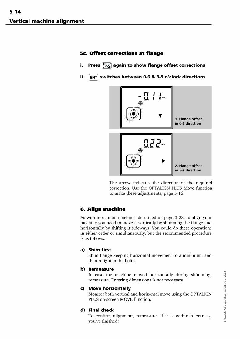
5-14
OPT
ALI
GN
PLU
S O
pera
ting
Inst
ruct
ions
07.
2002
Vertical machine alignment
6. Align machine
As with horizontal machines described on page 3-28, to align yourmachine you need to move it vertically by shimming the flange andhorizontally by shifting it sideways. You could do these operationsin either order or simultaneously, but the recommended procedureis as follows:
a) Shim firstShim flange keeping horizontal movement to a minimum, andthen retighten the bolts.
b) RemeasureIn case the machine moved horizontally during shimming,remeasure. Entering dimensions is not necessary.
c) Move horizontallyMonitor both vertical and horizontal move using the OPTALIGNPLUS on-screen MOVE function.
d) Final checkTo confirm alignment, remeasure. If it is within tolerances,you've finished!
5c. Offset corrections at flange
i. Press again to show flange offset corrections
ii. switches between 0-6 & 3-9 o'clock directions
The arrow indicates the direction of the requiredcorrection. Use the OPTALIGN PLUS Move functionto make these adjustments, page 5-16.
2. Flange offsetin 3-9 direction
1. Flange offsetin 0-6 direction
5-15
OPTA
LIGN
PLUS O
perating Instructions 07.2002
Vertical machine alignment
6b. Remeasure
A new set of alignment readings should be taken before movinghorizontally because the machines usually move slightly duringshimming. The remeasure process can be accomplished quickly asnew dimensions need no be re-entered. The initial dimensionsremain stored in the computer until new machine dimensions areentered. If horizontal misalignment values are outside tolerance,then the machine must be repositioned...
6a. Shimming at the flange
Here is the procedure for shimming the vertical machine.
1. Preparation!As for horizontal machines, i.) The machine bolts should beclean, undamaged and removeable, and ii.) You should have aset of good quality shims available e.g. LAMIBLOC or PERM-ABLOC - see page 6-9 for details.
2. Loosen boltsTry not to inadvertently move the machine horizontally.
3. Select shimming mode with After successful measurement press the 'Results' key three timesto show the shimming values at each defined bolt starting withbolt no. 1 (page 5-8). You can add further bolts at any time bypressing the DIM key.
4. Select bolt number & Press the arrow keys to select the first bolt you want to shim.The display switches slowly between the bolt number and theshimming value for that bolt. See page 5-13 for an example.
5. Shim machineInsert the correct shim thickness under the selected bolt.
6. Repeat for each boltStep through each bolt with the arrow keys and shim to thegiven value.
7. Tighten boltsWhen you have shimmed evenly all round the flange, tightenthe bolts again. The shimming is now complete.
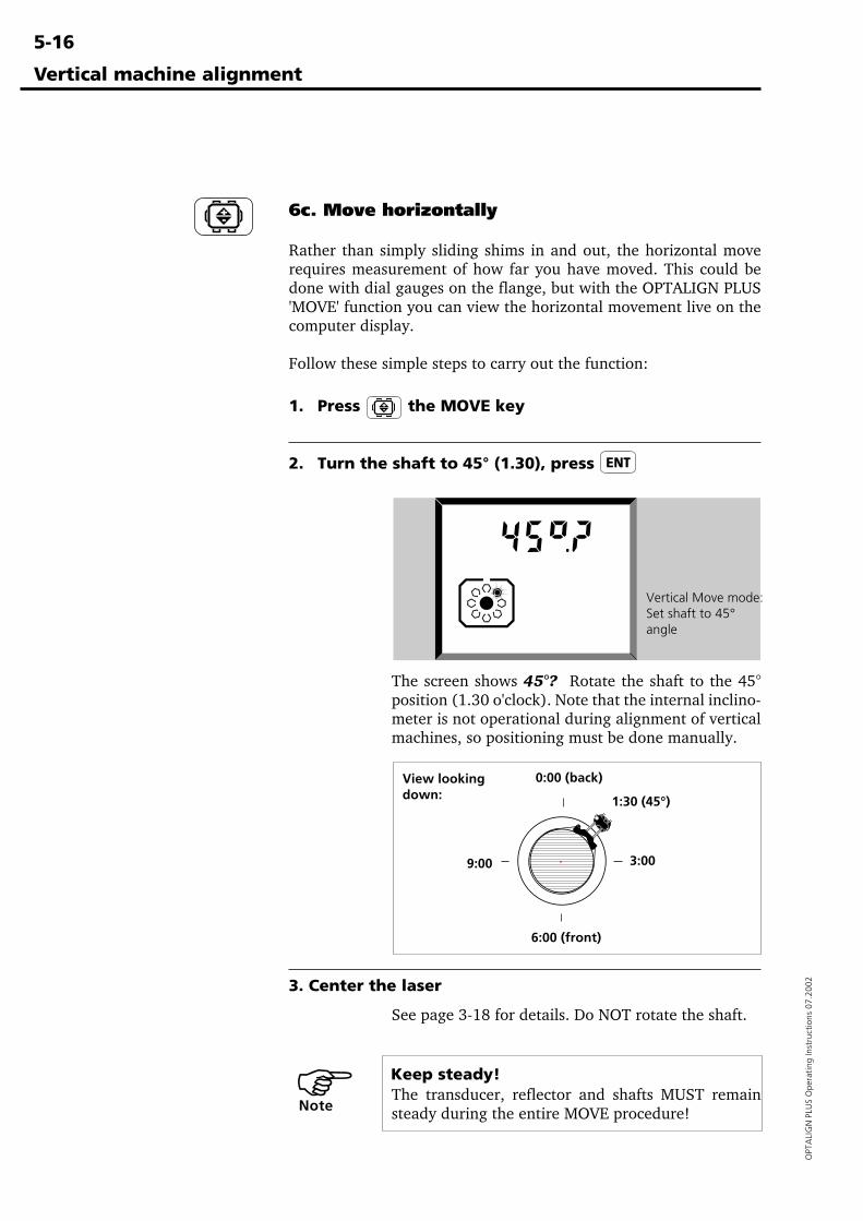
5-16
OPT
ALI
GN
PLU
S O
pera
ting
Inst
ruct
ions
07.
2002
Vertical machine alignment
6c. Move horizontally
Rather than simply sliding shims in and out, the horizontal moverequires measurement of how far you have moved. This could bedone with dial gauges on the flange, but with the OPTALIGN PLUS'MOVE' function you can view the horizontal movement live on thecomputer display.
Follow these simple steps to carry out the function:
1. Press the MOVE key
2. Turn the shaft to 45° (1.30), press
The screen shows 45°? Rotate the shaft to the 45°position (1.30 o'clock). Note that the internal inclino-meter is not operational during alignment of verticalmachines, so positioning must be done manually.
3. Center the laser
See page 3-18 for details. Do NOT rotate the shaft.
Keep steady!The transducer, reflector and shafts MUST remainsteady during the entire MOVE procedure!
Vertical Move mode:Set shaft to 45°angle
0:00 (back)
6:00 (front)
View lookingdown:
3:009:00
1:30 (45°)
�Note
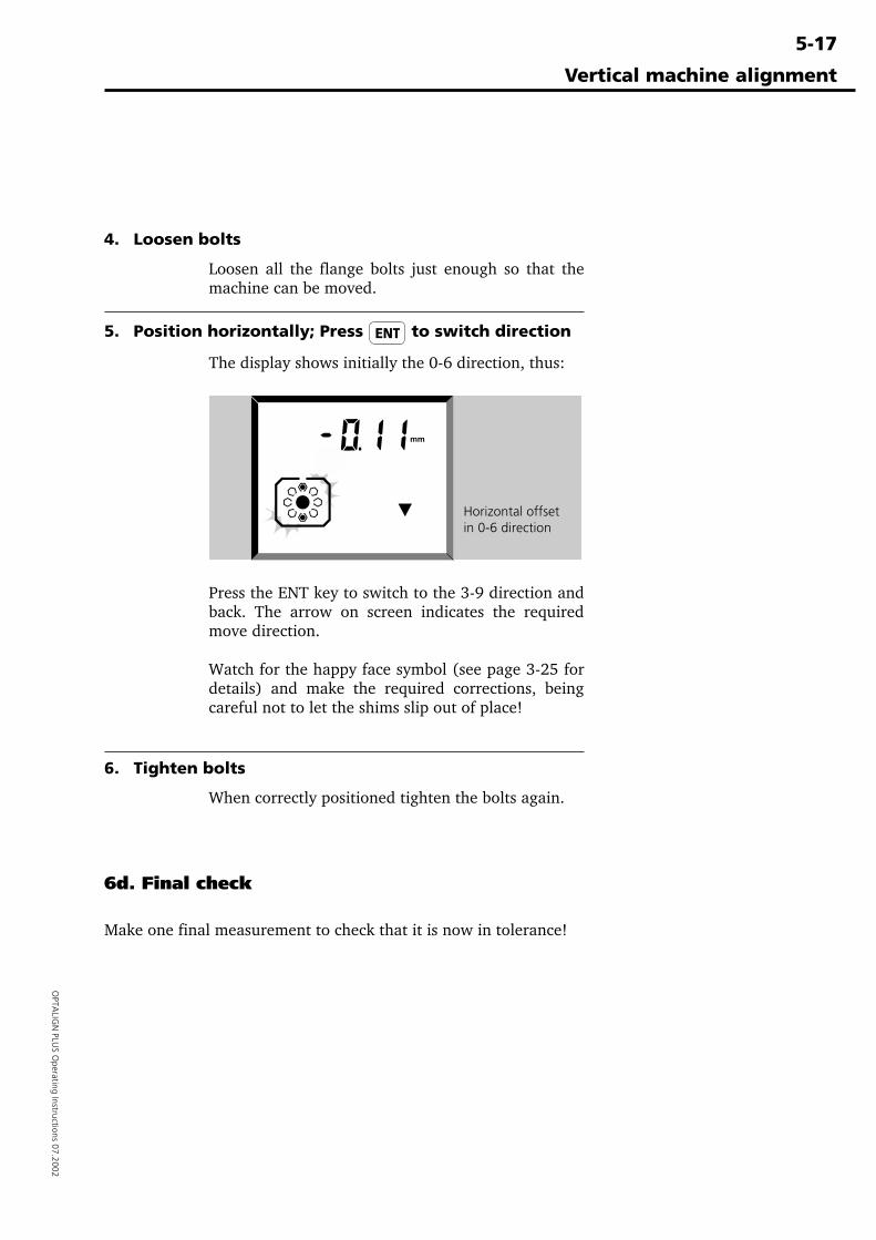
5-17
OPTA
LIGN
PLUS O
perating Instructions 07.2002
Vertical machine alignment
6d. Final check
Make one final measurement to check that it is now in tolerance!
4. Loosen bolts
Loosen all the flange bolts just enough so that themachine can be moved.
5. Position horizontally; Press to switch direction
The display shows initially the 0-6 direction, thus:
Press the ENT key to switch to the 3-9 direction andback. The arrow on screen indicates the requiredmove direction.
Watch for the happy face symbol (see page 3-25 fordetails) and make the required corrections, beingcareful not to let the shims slip out of place!
6. Tighten bolts
When correctly positioned tighten the bolts again.
Horizontal offsetin 0-6 direction
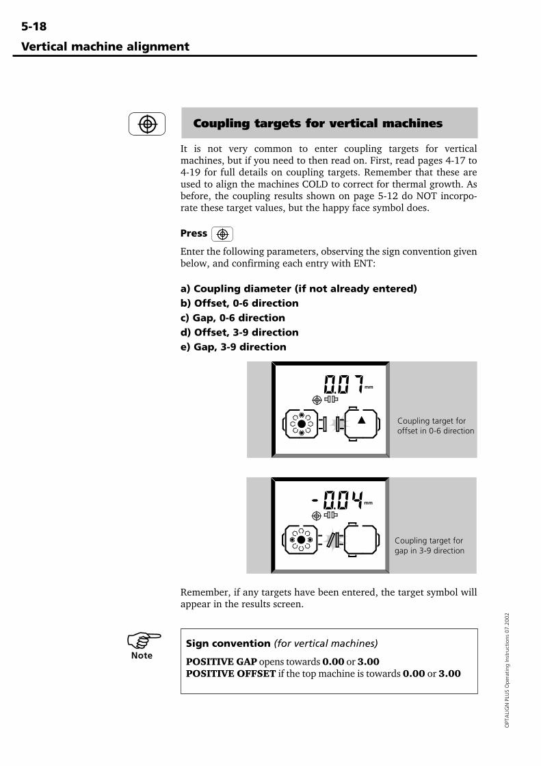
5-18
OPT
ALI
GN
PLU
S O
pera
ting
Inst
ruct
ions
07.
2002
Vertical machine alignment
Coupling targets for vertical machines
It is not very common to enter coupling targets for verticalmachines, but if you need to then read on. First, read pages 4-17 to4-19 for full details on coupling targets. Remember that these areused to align the machines COLD to correct for thermal growth. Asbefore, the coupling results shown on page 5-12 do NOT incorpo-rate these target values, but the happy face symbol does.
Press
Enter the following parameters, observing the sign convention givenbelow, and confirming each entry with ENT:
a) Coupling diameter (if not already entered)b) Offset, 0-6 directionc) Gap, 0-6 directiond) Offset, 3-9 directione) Gap, 3-9 direction
Coupling target foroffset in 0-6 direction
Coupling target forgap in 3-9 direction
Sign convention (for vertical machines)
POSITIVE GAP opens towards 0.00 or 3.00POSITIVE OFFSET if the top machine is towards 0.00 or 3.00
Remember, if any targets have been entered, the target symbol willappear in the results screen.
�Note
6-1
OPTA
LIGN
PLUS O
perating Instructions 07.2002
Appendix
Chapter 6 Appendix
This chapter contains a great deal of useful supplementary informa-tion on shaft alignment in general and on OPTALIGN PLUS inparticular.
Chapter 1 Introduction .......................................1-1 to 1-12
Chapter 2 Description .........................................2-1 to 2-14
Chapter 3 Horizontal alignment ........................3-1 to 3-38
Chapter 4 Further functions ...............................4-1 to 4-36
Chapter 5 Vertical alignment .............................5-1 to 5-18
Chapter 6 Appendix ........................................................ 6-1What is "alignment?" ................................................................... 6-2
Comparison of alignment methods ........................................... 6-3How accurate should alignment be? ......................................... 6-4Suggested Shaft Alignment Tolerances ..................................... 6-5
Machine preparation ................................................................... 6-6Solid, flat foundation ................................................................ 6-6Coupling play (backlash) .......................................................... 6-7Soft foot .................................................................................... 6-8Shims ........................................................................................ 6-9
OPTALIGN PLUS measurement principle ................................... 6-11OPTALIGN PLUS accessory brackets .......................................... 6-12
External reflector clamp ALI 5.116 ........................................ 6-17Advanced diagnosis and correction of soft foot ......................... 6-18
Soft foot examples .................................................................. 6-19Sample OPTALIGN PLUS report ................................................. 6-24Test functions ............................................................................ 6-28Replacing the transducer cable .................................................. 6-29Alignment Explorer and Editor .................................................. 6-30
The PC partner for OPTALIGN PLUS ....................................... 6-30Installation .............................................................................. 6-31PC connection ......................................................................... 6-31Establishing communication ................................................... 6-32File transfer ............................................................................ 6-33The OPTALIGN PLUS Editor .................................................... 6-37Using the Editor ...................................................................... 6-38
Troubleshooting checklist .......................................................... 6-41Warranty, service and care ......................................................... 6-43Error messages .......................................................................... 6-44OPTALIGN PLUS technical data ................................................. 6-45Index ......................................................................................... 6-46
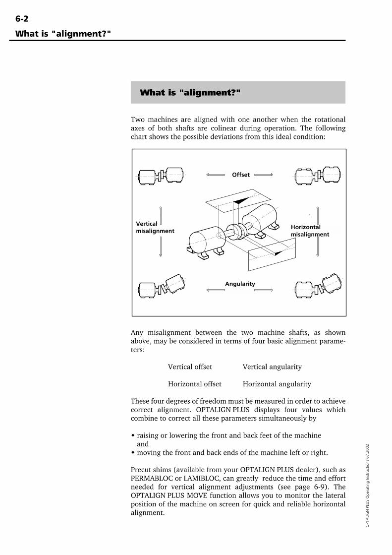
6-2
OPT
ALI
GN
PLU
S O
pera
ting
Inst
ruct
ions
07.
2002
What is "alignment?"
What is "alignment?"
Two machines are aligned with one another when the rotationalaxes of both shafts are colinear during operation. The followingchart shows the possible deviations from this ideal condition:
Offset
Angularity
Horizontalmisalignment
Verticalmisalignment
Any misalignment between the two machine shafts, as shownabove, may be considered in terms of four basic alignment parame-ters:
Vertical offset Vertical angularity
Horizontal offset Horizontal angularity
These four degrees of freedom must be measured in order to achievecorrect alignment. OPTALIGN PLUS displays four values whichcombine to correct all these parameters simultaneously by
� raising or lowering the front and back feet of the machine and� moving the front and back ends of the machine left or right.
Precut shims (available from your OPTALIGN PLUS dealer), such asPERMABLOC or LAMIBLOC, can greatly reduce the time and effortneeded for vertical alignment adjustments (see page 6-9). TheOPTALIGN PLUS MOVE function allows you to monitor the lateralposition of the machine on screen for quick and reliable horizontalalignment.
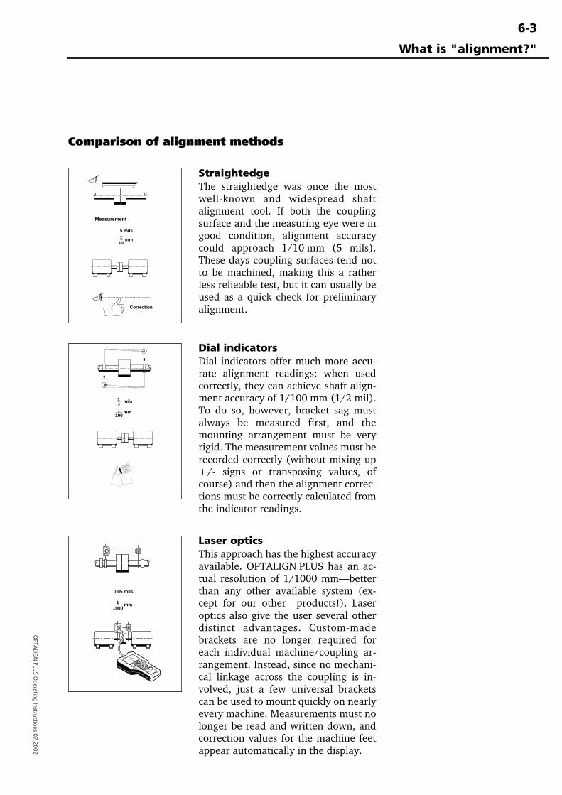
6-3
OPTA
LIGN
PLUS O
perating Instructions 07.2002
What is "alignment?"
Comparison of alignment methods
MeasurementMessen
CorrectionKorrigieren
5 mils
mm110
StraightedgeThe straightedge was once the mostwell-known and widespread shaftalignment tool. If both the couplingsurface and the measuring eye were ingood condition, alignment accuracycould approach 1/10 mm (5 mils).These days coupling surfaces tend notto be machined, making this a ratherless relieable test, but it can usually beused as a quick check for preliminaryalignment.
Dial indicatorsDial indicators offer much more accu-rate alignment readings: when usedcorrectly, they can achieve shaft align-ment accuracy of 1/100 mm (1/2 mil).To do so, however, bracket sag mustalways be measured first, and themounting arrangement must be veryrigid. The measurement values must berecorded correctly (without mixing up+/- signs or transposing values, ofcourse) and then the alignment correc-tions must be correctly calculated fromthe indicator readings.
Laser opticsThis approach has the highest accuracyavailable. OPTALIGN PLUS has an ac-tual resolution of 1/1000 mm—betterthan any other available system (ex-cept for our other products!). Laseroptics also give the user several otherdistinct advantages. Custom-madebrackets are no longer required foreach individual machine/coupling ar-rangement. Instead, since no mechani-cal linkage across the coupling is in-volved, just a few universal bracketscan be used to mount quickly on nearlyevery machine. Measurements must nolonger be read and written down, andcorrection values for the machine feetappear automatically in the display.
2mils 1
mm1100
mm1000
1
0,05 mils
45
6
12
3
0.
-
M
F
78
9DIM
/CLR
ENT+ -
6-4
OPT
ALI
GN
PLU
S O
pera
ting
Inst
ruct
ions
07.
2002
What is "alignment?"
How accurate should alignment be?
The suggested alignment tolerances shown at right are generalvalues based upon experience and should not be exceeded. They areto be used only if existing in-house standards or the manufacturer ofthe machine or coupling prescribe no other values.
Consider all values listed to be the maximum allowable deviationfrom the alignment target, be it zero or some desired value tocompensate for thermal growth. In most cases, a quick glance at thetable will tell whether coupling misalignment is allowable or not.
As an example, a machine running at 1500 rpm has coupling offsetsof -0.04 mm vertically and +0.02 mm horizontally: both thesevalues fall within the "excellent" limit of 0.06 mm. Or in inches: e.g.at 1800 rpm offsets are -1.3 mils vertically and +.6 mils horizontal-ly: both values fall within "excellent" limit of 2 mils.
Angularity is usually measured in terms of gap width at the edge ofthe coupling. For a given amount of angularity, the larger thediameter, the wider the gap at the coupling edge. The table listsvalues for coupling diameters of 100 mm or 10". You may compareresults directly by entering this coupling diameter intoOPTALIGN PLUS, or alternatively, if actual coupling diameter isentered, then multiply the value from the table by the appropriatefactor.
For example, a machine running at 1500 rpm has a coupling ofdiameter 75 mm. At this diameter, the maximum allowable gapwould be
(0.07 mm) x 75/100 = 0.0525 mm (or 5/100 mm)
In inches: 1800 rpm, diameter = 20"; 5 mils x 20"/10" = 10 mils
For spacer shafts, the table gives the maximum allowable offset foreach 100 mm or inch of spacer shaft length. To take an example, amachine running at 6000 rpm with a 300 mm spacer shaft installedwould allow a maximum offset of
(0.03 mm) x 300/100 = 0.09 mm (or 9/100 mm)
at either coupling at the ends of the spacer shaft.In inches: 7200 rpm, Length = 10"; 0.25 mils x 10"/1" = 2.5 mils
"Acceptable" limits are calculated from sliding velocity of lubricatedsteel on steel, using a conservative value of 12 mm/sec. (0.5 in./sec.) for allowable sliding velocity. These values also coincide withthose derived from elastomer shear rates, so they also apply to shortcouplings with flexible elements. The "excellent" values draw onvibration observations made upon a wide variety of industrialmachines to determine the critical misalignment for vibration;however, compliance with these tolerance values does not guaran-tee vibration-free operation of a particular machine.
Since rigid (flanged) couplings have no tolerance for misalignment,they should be aligned as accurately as possible.
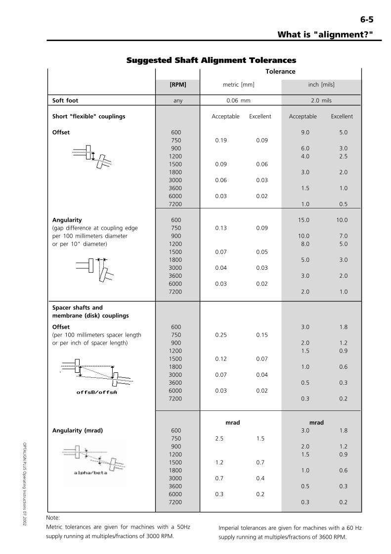
6-5
OPTA
LIGN
PLUS O
perating Instructions 07.2002
What is "alignment?"
Suggested Shaft Alignment Tolerances
Note:
Metric tolerances are given for machines with a 50Hz
supply running at multiples/fractions of 3000 RPM.Imperial tolerances are given for machines with a 60 Hz
supply running at multiples/fractions of 3600 RPM.
Tolerance
[RPM] metric [mm] inch [mils]
Soft foot any 0.06 mm 2.0 mils
Short "flexible" couplings Acceptable Excellent Acceptable Excellent
Offset 600 9.0 5.0 750 0.19 0.09 900 6.0 3.01200 4.0 2.51500 0.09 0.061800 3.0 2.03000 0.06 0.033600 1.5 1.06000 0.03 0.027200 1.0 0.5
Angularity 600 15.0 10.0(gap difference at coupling edge 750 0.13 0.09per 100 millimeters diameter 900 10.0 7.0or per 10" diameter) 1200 8.0 5.0
1500 0.07 0.051800 5.0 3.03000 0.04 0.033600 3.0 2.06000 0.03 0.027200 2.0 1.0
Spacer shafts andmembrane (disk) couplings
Offset 600 3.0 1.8(per 100 millimeters spacer length 750 0.25 0.15or per inch of spacer length) 900 2.0 1.2
1200 1.5 0.91500 0.12 0.071800 1.0 0.63000 0.07 0.043600 0.5 0.36000 0.03 0.027200 0.3 0.2
mrad mradAngularity (mrad) 600 3.0 1.8
750 2.5 1.5 900 2.0 1.21200 1.5 0.91500 1.2 0.71800 1.0 0.63000 0.7 0.43600 0.5 0.36000 0.3 0.27200 0.3 0.2
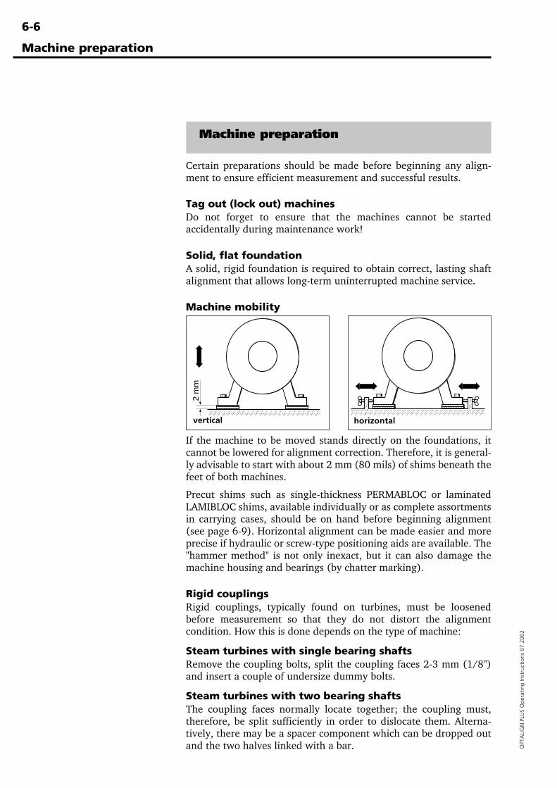
6-6
OPT
ALI
GN
PLU
S O
pera
ting
Inst
ruct
ions
07.
2002
Machine preparation
Machine preparation
Certain preparations should be made before beginning any align-ment to ensure efficient measurement and successful results.
Tag out (lock out) machinesDo not forget to ensure that the machines cannot be startedaccidentally during maintenance work!
Solid, flat foundationA solid, rigid foundation is required to obtain correct, lasting shaftalignment that allows long-term uninterrupted machine service.
Machine mobility
If the machine to be moved stands directly on the foundations, itcannot be lowered for alignment correction. Therefore, it is general-ly advisable to start with about 2 mm (80 mils) of shims beneath thefeet of both machines.
Precut shims such as single-thickness PERMABLOC or laminatedLAMIBLOC shims, available individually or as complete assortmentsin carrying cases, should be on hand before beginning alignment(see page 6-9). Horizontal alignment can be made easier and moreprecise if hydraulic or screw-type positioning aids are available. The"hammer method" is not only inexact, but it can also damage themachine housing and bearings (by chatter marking).
Rigid couplingsRigid couplings, typically found on turbines, must be loosenedbefore measurement so that they do not distort the alignmentcondition. How this is done depends on the type of machine:
Steam turbines with single bearing shaftsRemove the coupling bolts, split the coupling faces 2-3 mm (1/8")and insert a couple of undersize dummy bolts.
Steam turbines with two bearing shaftsThe coupling faces normally locate together; the coupling must,therefore, be split sufficiently in order to dislocate them. Alterna-tively, there may be a spacer component which can be dropped outand the two halves linked with a bar.
horizontalvertical
2 m
m
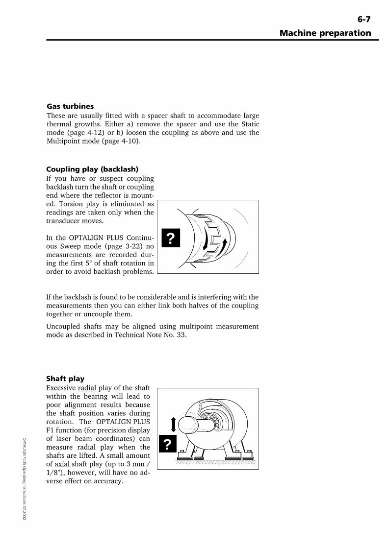
6-7
OPTA
LIGN
PLUS O
perating Instructions 07.2002
Machine preparation
Shaft playExcessive radial play of the shaftwithin the bearing will lead topoor alignment results becausethe shaft position varies duringrotation. The OPTALIGN PLUSF1 function (for precision displayof laser beam coordinates) canmeasure radial play when theshafts are lifted. A small amountof axial shaft play (up to 3 mm /1/8"), however, will have no ad-verse effect on accuracy.
Coupling play (backlash)If you have or suspect couplingbacklash turn the shaft or couplingend where the reflector is mount-ed. Torsion play is eliminated asreadings are taken only when thetransducer moves.
In the OPTALIGN PLUS Continu-ous Sweep mode (page 3-22) nomeasurements are recorded dur-ing the first 5° of shaft rotation inorder to avoid backlash problems.
?
Gas turbinesThese are usually fitted with a spacer shaft to accommodate largethermal growths. Either a) remove the spacer and use the Staticmode (page 4-12) or b) loosen the coupling as above and use theMultipoint mode (page 4-10).
If the backlash is found to be considerable and is interfering with themeasurements then you can either link both halves of the couplingtogether or uncouple them.
Uncoupled shafts may be aligned using multipoint measurementmode as described in Technical Note No. 33.
?
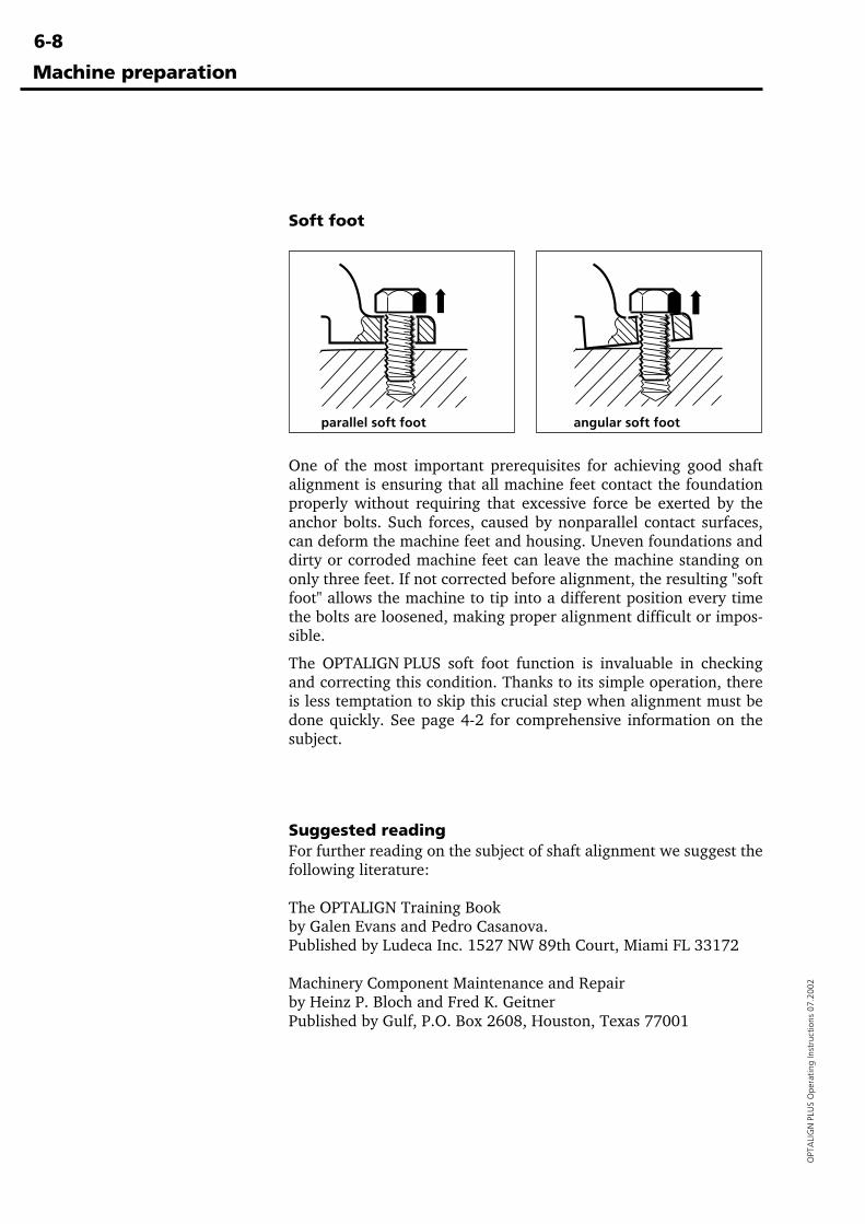
6-8
OPT
ALI
GN
PLU
S O
pera
ting
Inst
ruct
ions
07.
2002
Machine preparation
One of the most important prerequisites for achieving good shaftalignment is ensuring that all machine feet contact the foundationproperly without requiring that excessive force be exerted by theanchor bolts. Such forces, caused by nonparallel contact surfaces,can deform the machine feet and housing. Uneven foundations anddirty or corroded machine feet can leave the machine standing ononly three feet. If not corrected before alignment, the resulting "softfoot" allows the machine to tip into a different position every timethe bolts are loosened, making proper alignment difficult or impos-sible.
The OPTALIGN PLUS soft foot function is invaluable in checkingand correcting this condition. Thanks to its simple operation, thereis less temptation to skip this crucial step when alignment must bedone quickly. See page 4-2 for comprehensive information on thesubject.
Soft foot
parallel soft foot angular soft foot
Suggested readingFor further reading on the subject of shaft alignment we suggest thefollowing literature:
The OPTALIGN Training Bookby Galen Evans and Pedro Casanova.Published by Ludeca Inc. 1527 NW 89th Court, Miami FL 33172
Machinery Component Maintenance and Repairby Heinz P. Bloch and Fred K. GeitnerPublished by Gulf, P.O. Box 2608, Houston, Texas 77001
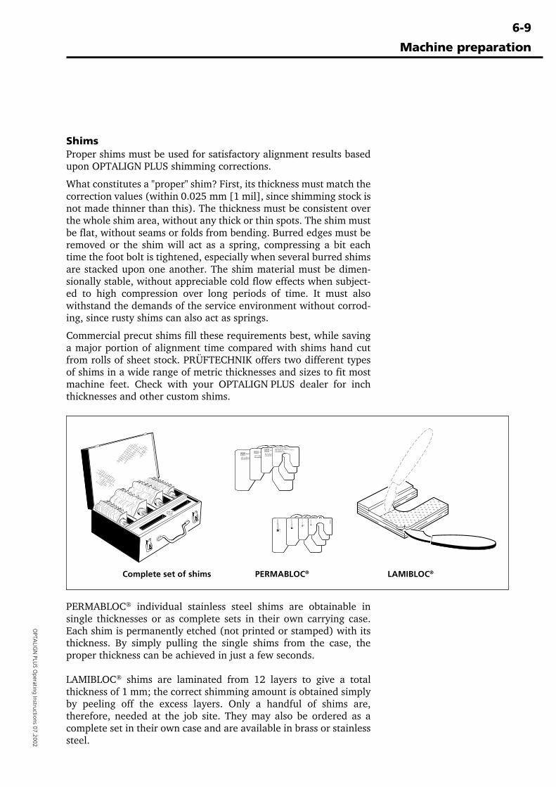
6-9
OPTA
LIGN
PLUS O
perating Instructions 07.2002Permabloc®
Complete set of shims PERMABLOC® LAMIBLOC®
Machine preparation
ShimsProper shims must be used for satisfactory alignment results basedupon OPTALIGN PLUS shimming corrections.
What constitutes a "proper" shim? First, its thickness must match thecorrection values (within 0.025 mm [1 mil], since shimming stock isnot made thinner than this). The thickness must be consistent overthe whole shim area, without any thick or thin spots. The shim mustbe flat, without seams or folds from bending. Burred edges must beremoved or the shim will act as a spring, compressing a bit eachtime the foot bolt is tightened, especially when several burred shimsare stacked upon one another. The shim material must be dimen-sionally stable, without appreciable cold flow effects when subject-ed to high compression over long periods of time. It must alsowithstand the demands of the service environment without corrod-ing, since rusty shims can also act as springs.
Commercial precut shims fill these requirements best, while savinga major portion of alignment time compared with shims hand cutfrom rolls of sheet stock. PRÜFTECHNIK offers two different typesof shims in a wide range of metric thicknesses and sizes to fit mostmachine feet. Check with your OPTALIGN PLUS dealer for inchthicknesses and other custom shims.
PERMABLOC® individual stainless steel shims are obtainable insingle thicknesses or as complete sets in their own carrying case.Each shim is permanently etched (not printed or stamped) with itsthickness. By simply pulling the single shims from the case, theproper thickness can be achieved in just a few seconds.
LAMIBLOC® shims are laminated from 12 layers to give a totalthickness of 1 mm; the correct shimming amount is obtained simplyby peeling off the excess layers. Only a handful of shims are,therefore, needed at the job site. They may also be ordered as acomplete set in their own case and are available in brass or stainlesssteel.

6-1
0
OPTALIGN PLUS Operating Instructions 07.2002
(Blank page)
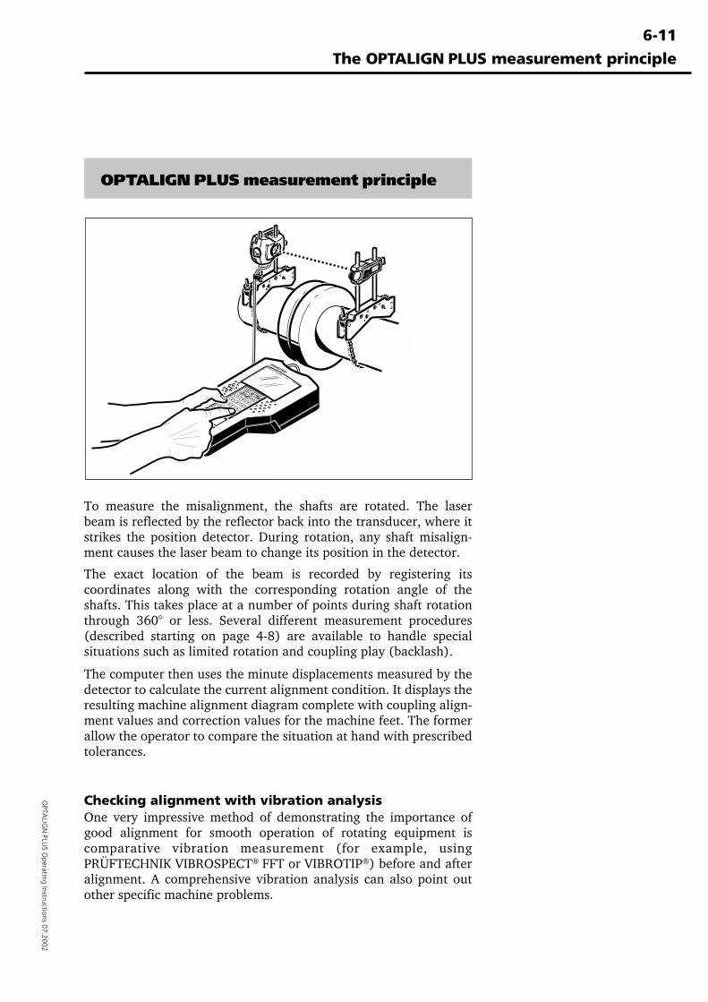
6-11
OPTA
LIGN
PLUS O
perating Instructions 07.2002
The OPTALIGN PLUS measurement principle
OPTALIGN PLUS measurement principle
To measure the misalignment, the shafts are rotated. The laserbeam is reflected by the reflector back into the transducer, where itstrikes the position detector. During rotation, any shaft misalign-ment causes the laser beam to change its position in the detector.
The exact location of the beam is recorded by registering itscoordinates along with the corresponding rotation angle of theshafts. This takes place at a number of points during shaft rotationthrough 360° or less. Several different measurement procedures(described starting on page 4-8) are available to handle specialsituations such as limited rotation and coupling play (backlash).
The computer then uses the minute displacements measured by thedetector to calculate the current alignment condition. It displays theresulting machine alignment diagram complete with coupling align-ment values and correction values for the machine feet. The formerallow the operator to compare the situation at hand with prescribedtolerances.
Checking alignment with vibration analysisOne very impressive method of demonstrating the importance ofgood alignment for smooth operation of rotating equipment iscomparative vibration measurement (for example, usingPRÜFTECHNIK VIBROSPECT® FFT or VIBROTIP®) before and afteralignment. A comprehensive vibration analysis can also point outother specific machine problems.
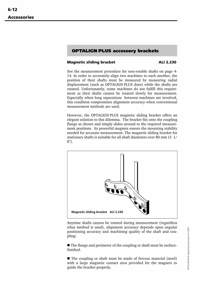
6-12
OPT
ALI
GN
PLU
S O
pera
ting
Inst
ruct
ions
07.
2002
Accessories
Magnetic sliding bracket ALI 2.230
See the measurement procedure for non-rotable shafts on page 4-14. In order to accurately align two machines to each another, theposition of their shafts must be measured by measuring radialdisplacement (such as OPTALIGN PLUS does) while the shafts arerotated. Unfortunately, some machines do not fulfill this require-ment as their shafts cannot be rotated slowly for measurement.Especially when long separations between machines are involved,this condition compromises alignment accuracy when conventionalmeasurement methods are used.
However, the OPTALIGN PLUS magnetic sliding bracket offers anelegant solution to this dilemma. The bracket fits onto the couplingflange as shown and simply slides around to the required measure-ment positions. Its powerful magnets ensure the mounting stabilityneeded for accurate measurement. The magnetic sliding bracket forstationary shafts is suitable for all shaft diameters over 80 mm (3 1/8").
Anytime shafts cannot be rotated during measurement (regardlesswhat method is used), alignment accuracy depends upon angularpositioning accuracy and machining quality of the shaft and cou-pling:
� The flange and perimeter of the coupling or shaft must be surface-finished.
� The coupling or shaft must be made of ferrous material (steel)with a large magnetic contact area provided for the magnets toguide the bracket properly.
OPTALIGN PLUS accessory brackets
Magnetic sliding bracket ALI 2.230
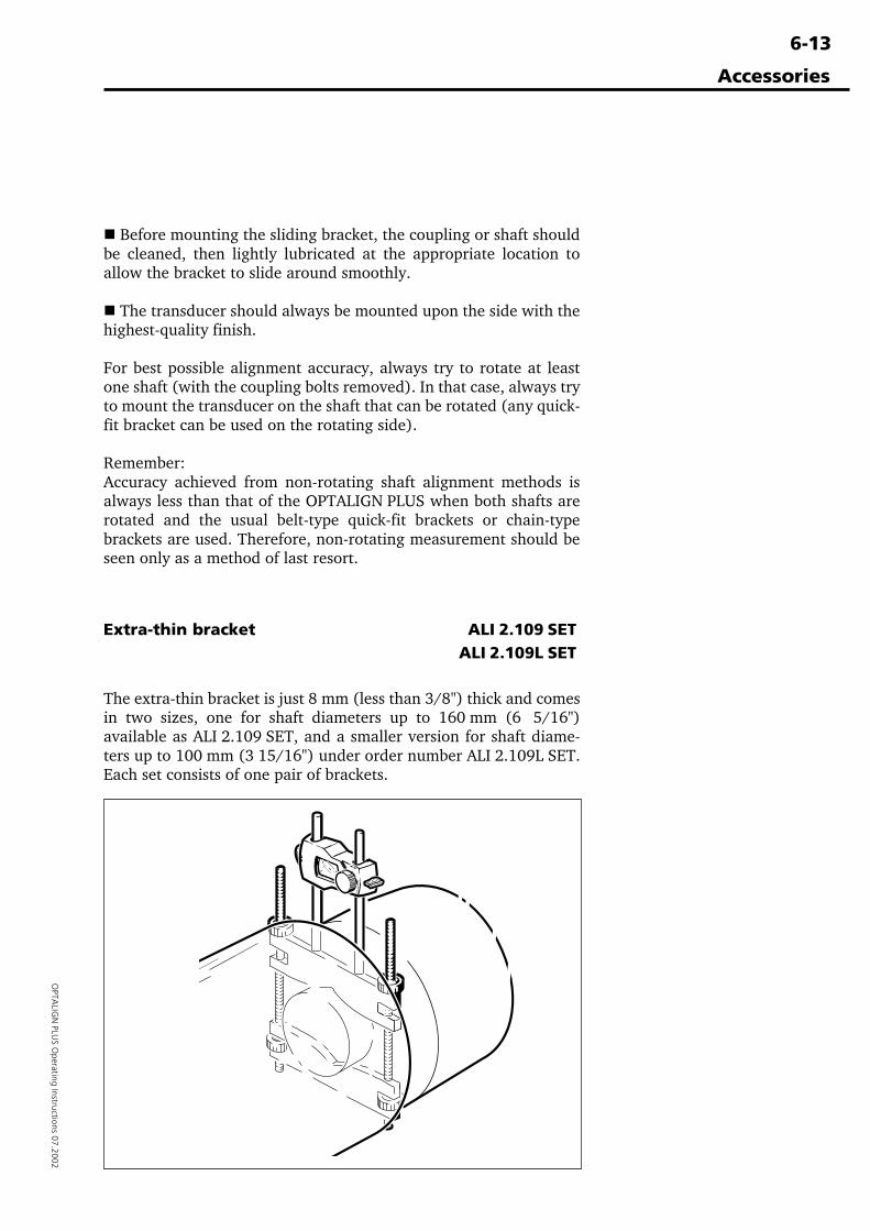
6-13
OPTA
LIGN
PLUS O
perating Instructions 07.2002
Accessories
� Before mounting the sliding bracket, the coupling or shaft shouldbe cleaned, then lightly lubricated at the appropriate location toallow the bracket to slide around smoothly.
� The transducer should always be mounted upon the side with thehighest-quality finish.
For best possible alignment accuracy, always try to rotate at leastone shaft (with the coupling bolts removed). In that case, always tryto mount the transducer on the shaft that can be rotated (any quick-fit bracket can be used on the rotating side).
Remember:Accuracy achieved from non-rotating shaft alignment methods isalways less than that of the OPTALIGN PLUS when both shafts arerotated and the usual belt-type quick-fit brackets or chain-typebrackets are used. Therefore, non-rotating measurement should beseen only as a method of last resort.
Extra-thin bracket ALI 2.109 SETALI 2.109L SET
The extra-thin bracket is just 8 mm (less than 3/8") thick and comesin two sizes, one for shaft diameters up to 160 mm (6 5/16")available as ALI 2.109 SET, and a smaller version for shaft diame-ters up to 100 mm (3 15/16") under order number ALI 2.109L SET.Each set consists of one pair of brackets.
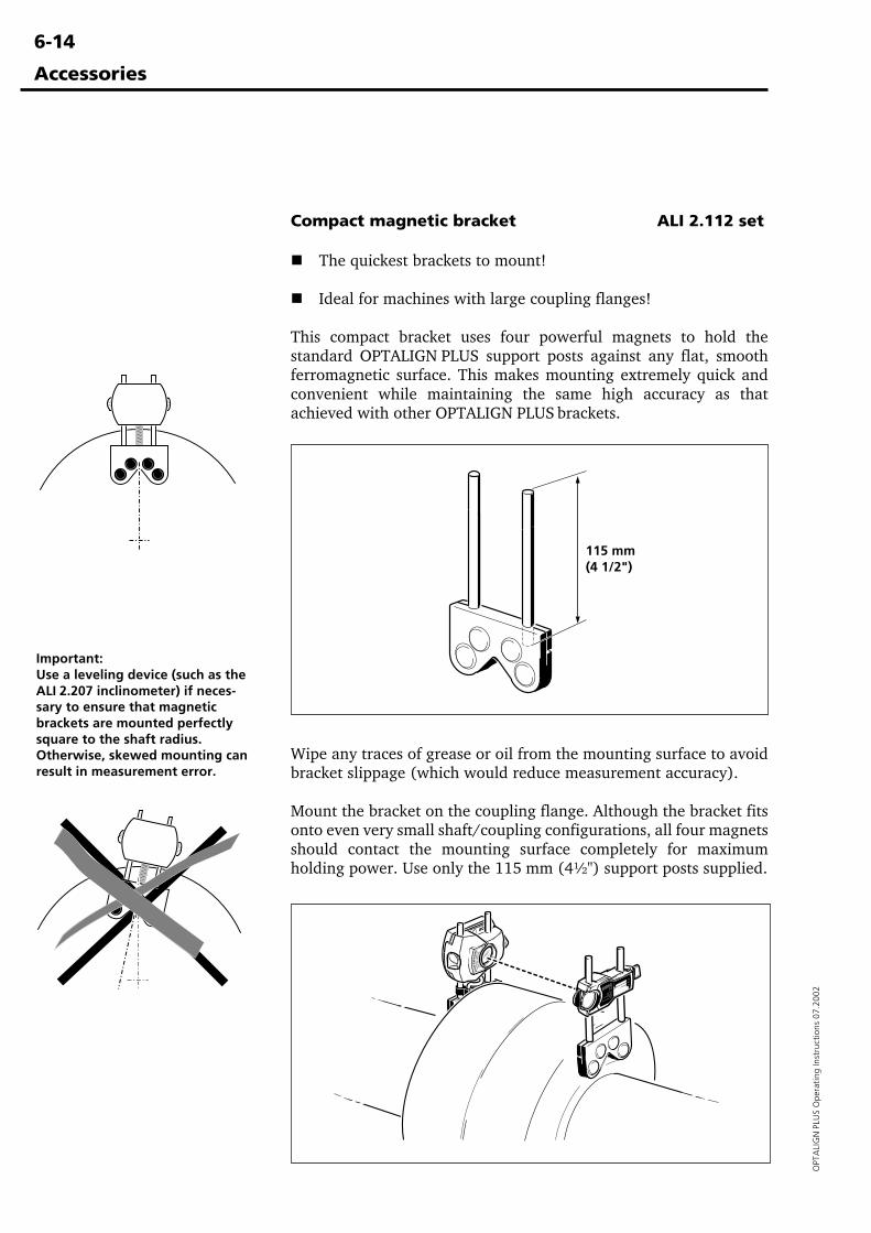
6-14
OPT
ALI
GN
PLU
S O
pera
ting
Inst
ruct
ions
07.
2002
Compact magnetic bracket ALI 2.112 set
��The quickest brackets to mount!
��Ideal for machines with large coupling flanges!
This compact bracket uses four powerful magnets to hold thestandard OPTALIGN PLUS support posts against any flat, smoothferromagnetic surface. This makes mounting extremely quick andconvenient while maintaining the same high accuracy as thatachieved with other OPTALIGN PLUS brackets.
Accessories
115 mm(4 1/2")
Wipe any traces of grease or oil from the mounting surface to avoidbracket slippage (which would reduce measurement accuracy).
Mount the bracket on the coupling flange. Although the bracket fitsonto even very small shaft/coupling configurations, all four magnetsshould contact the mounting surface completely for maximumholding power. Use only the 115 mm (4½") support posts supplied.
Important:Use a leveling device (such as theALI 2.207 inclinometer) if neces-sary to ensure that magneticbrackets are mounted perfectlysquare to the shaft radius.Otherwise, skewed mounting canresult in measurement error.
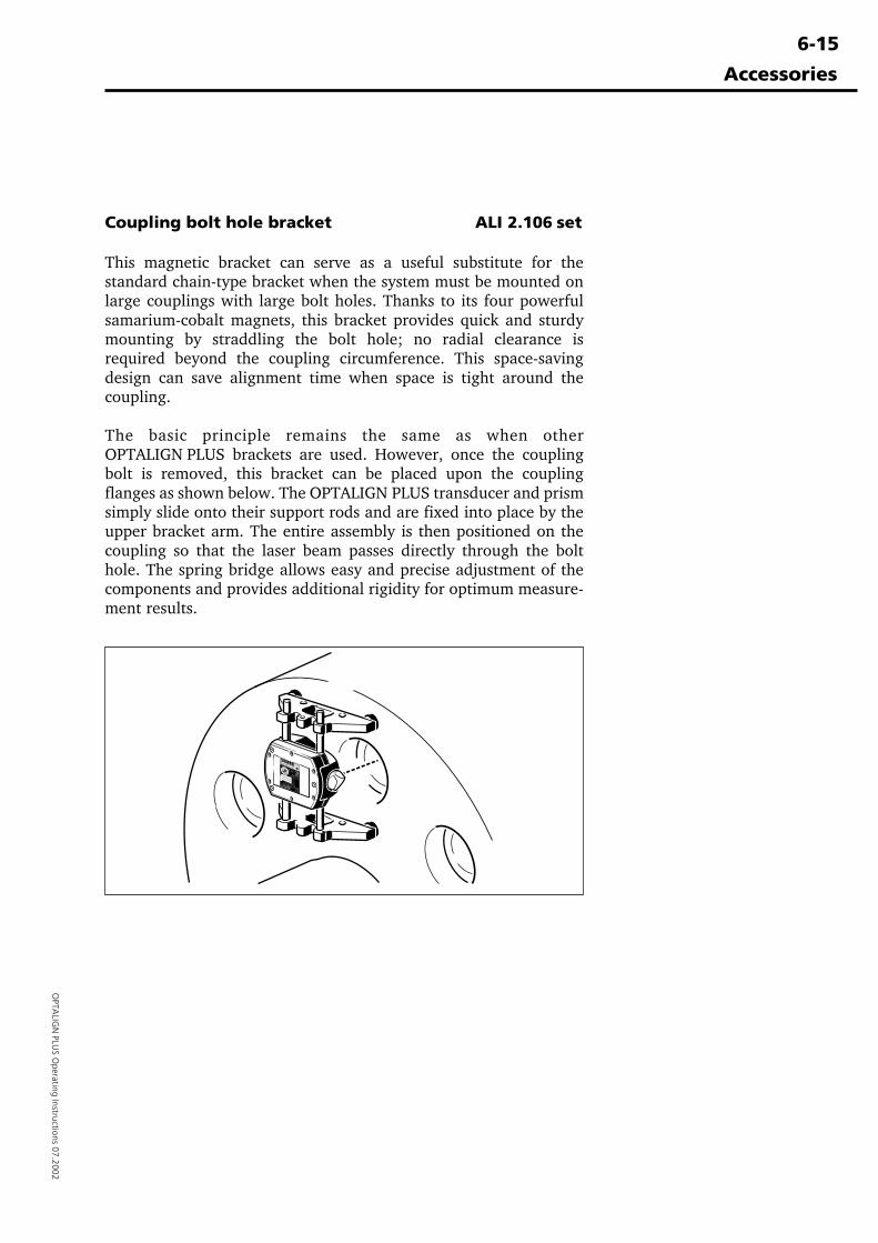
6-15
OPTA
LIGN
PLUS O
perating Instructions 07.2002
Accessories
Coupling bolt hole bracket ALI 2.106 set
This magnetic bracket can serve as a useful substitute for thestandard chain-type bracket when the system must be mounted onlarge couplings with large bolt holes. Thanks to its four powerfulsamarium-cobalt magnets, this bracket provides quick and sturdymounting by straddling the bolt hole; no radial clearance isrequired beyond the coupling circumference. This space-savingdesign can save alignment time when space is tight around thecoupling.
The basic principle remains the same as when otherOPTALIGN PLUS brackets are used. However, once the couplingbolt is removed, this bracket can be placed upon the couplingflanges as shown below. The OPTALIGN PLUS transducer and prismsimply slide onto their support rods and are fixed into place by theupper bracket arm. The entire assembly is then positioned on thecoupling so that the laser beam passes directly through the bolthole. The spring bridge allows easy and precise adjustment of thecomponents and provides additional rigidity for optimum measure-ment results.
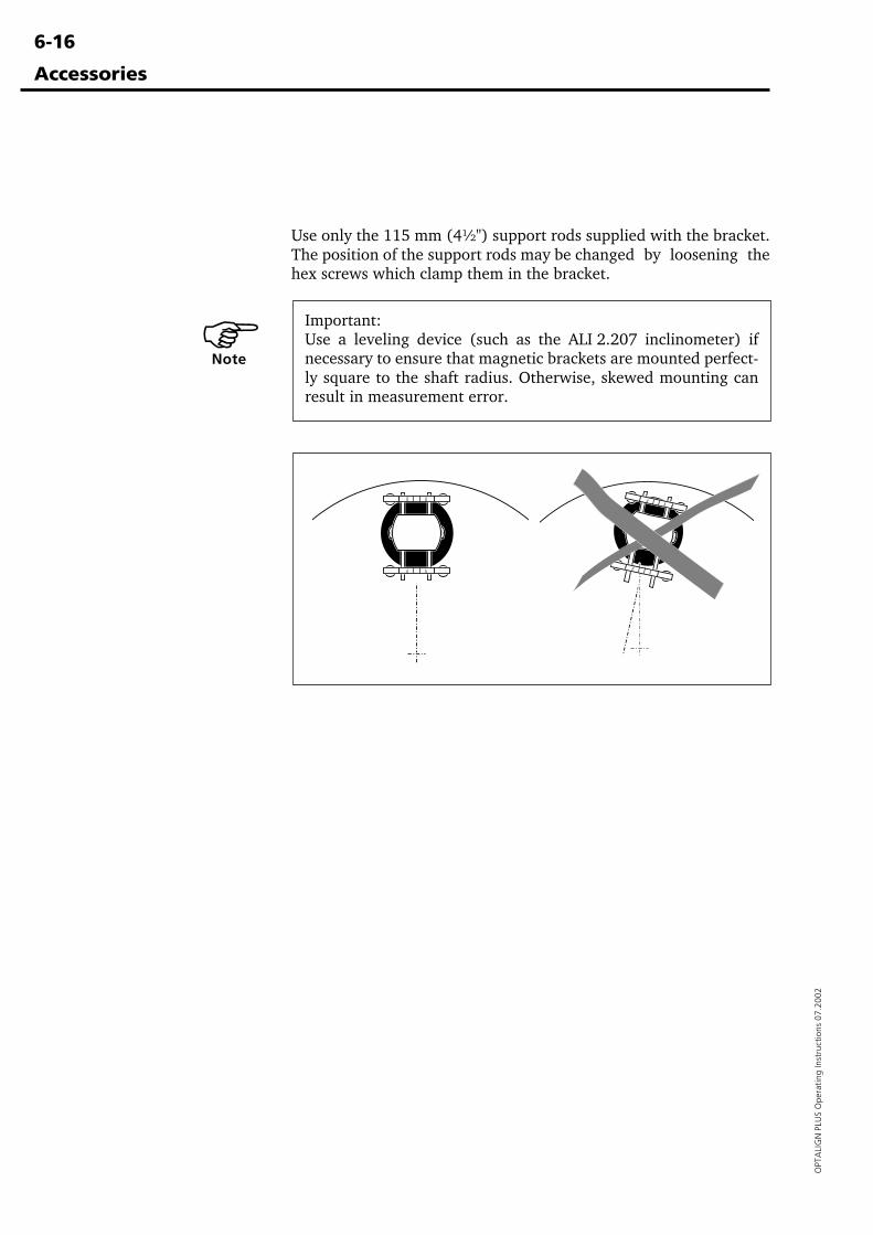
6-16
OPT
ALI
GN
PLU
S O
pera
ting
Inst
ruct
ions
07.
2002
Important:Use a leveling device (such as the ALI 2.207 inclinometer) ifnecessary to ensure that magnetic brackets are mounted perfect-ly square to the shaft radius. Otherwise, skewed mounting canresult in measurement error.
Accessories
Use only the 115 mm (4½") support rods supplied with the bracket.The position of the support rods may be changed by loosening thehex screws which clamp them in the bracket.
�Note
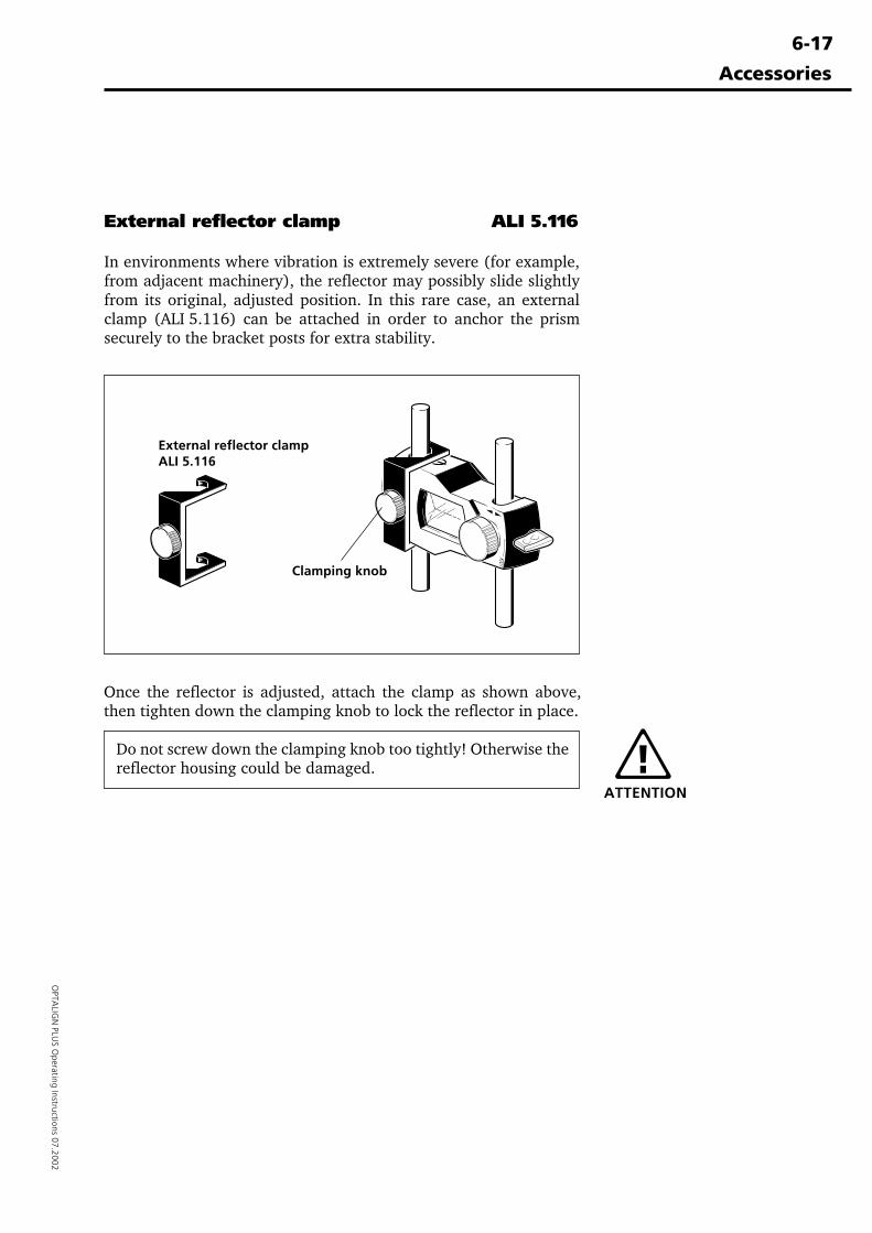
6-17
OPTA
LIGN
PLUS O
perating Instructions 07.2002
External reflector clamp ALI 5.116
In environments where vibration is extremely severe (for example,from adjacent machinery), the reflector may possibly slide slightlyfrom its original, adjusted position. In this rare case, an externalclamp (ALI 5.116) can be attached in order to anchor the prismsecurely to the bracket posts for extra stability.
Accessories
Once the reflector is adjusted, attach the clamp as shown above,then tighten down the clamping knob to lock the reflector in place.
Do not screw down the clamping knob too tightly! Otherwise thereflector housing could be damaged.
ATTENTION
External reflector clampALI 5.116
Clamping knob
6-18
OPT
ALI
GN
PLU
S O
pera
ting
Inst
ruct
ions
07.
2002
Advanced diagnosis & correction of soft foot
Besides the two most common types of soft foot previously dis-cussed (page 4-2), parallel and angular soft foot, a number of otherproblems may cause excessive soft foot readings:
If OPTALIGN PLUS measures a soft foot, but feeler gauges cannot beinserted beneath the foot, there may be rust or dirt beneath the foot:This type of 'spongy' foreign matter can expand when the foot bolt isloosened so that OPTALIGN PLUS reads a soft foot, yet still keep afeeler gauge from being inserted. Correct the situation by using apower wire brush to clean the undersides of the machine feet andthe base, and replace any damaged shims. Take care to completelyremove all dust and dirt from the top and sides of the feet as well toprevent recontamination, and limit the number of shims beneathany one foot to 4.
External forces such as those exerted by attached piping, supports,couplings or other machine parts may induce soft foot readings untilthe shaft alignment is improved. This may be checked by removingthe suspected source of strain, then taking a second set of readingsfor comparison.
Sometimes OPTALIGN PLUS will register little or no soft foot, yetfeeler gauge measurements indicate quite a substantial gap beneaththe machine feet. This can occur if either the base or machine feetbend without bending the machine housing (for example due tounderdimensioning or damage). As a result, shimming correctionsmay not bring the expected improvement, but often satisfactoryalignment may still be achieved, even without filling the foot gapbeforehand. So long as the OPTALIGN PLUS shows no soft footreading when the foot bolts are tightened or loosened, the shaft isnot moving, so no harm can occur to the rotor, bearings or coupling.
In some cases, the OPTALIGN PLUS soft foot function registers shaftdeflections which are actually caused by irregularities of theindividual feet. The only way to check the contact of each foot to themachine base is to use feeler gauges at the corners of the feet. Thesereadings may then be considered in combination with theOPTALIGN PLUS soft foot results as illustrated by the examples onthe following pages.
For maximum accuracy during soft foot measurement (andespecially when coupling play is present), the shafts should berotated so that the sensors are oriented vertically (12:00 - 6:00direction).
�Note
Advanced diagnosis andcorrection of soft foot
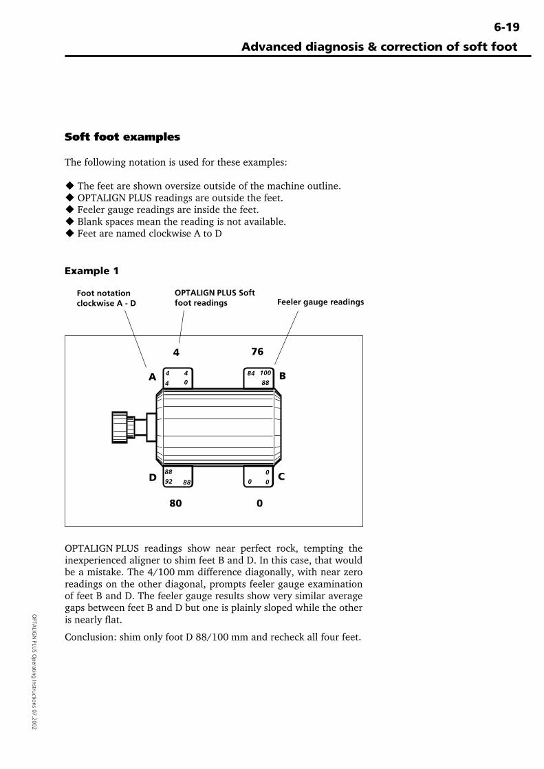
6-19
OPTA
LIGN
PLUS O
perating Instructions 07.2002
Advanced diagnosis & correction of soft foot
Soft foot examples
The following notation is used for these examples:
� The feet are shown oversize outside of the machine outline.� OPTALIGN PLUS readings are outside the feet.� Feeler gauge readings are inside the feet.� Blank spaces mean the reading is not available.� Feet are named clockwise A to D
Example 1
0
4
4
40
100
88
88
92 88
0
0
84
0
80
4 76
Foot notationclockwise A - D
OPTALIGN PLUS Softfoot readings Feeler gauge readings
OPTALIGN PLUS readings show near perfect rock, tempting theinexperienced aligner to shim feet B and D. In this case, that wouldbe a mistake. The 4/100 mm difference diagonally, with near zeroreadings on the other diagonal, prompts feeler gauge examinationof feet B and D. The feeler gauge results show very similar averagegaps between feet B and D but one is plainly sloped while the otheris nearly flat.
Conclusion: shim only foot D 88/100 mm and recheck all four feet.
CD
A B
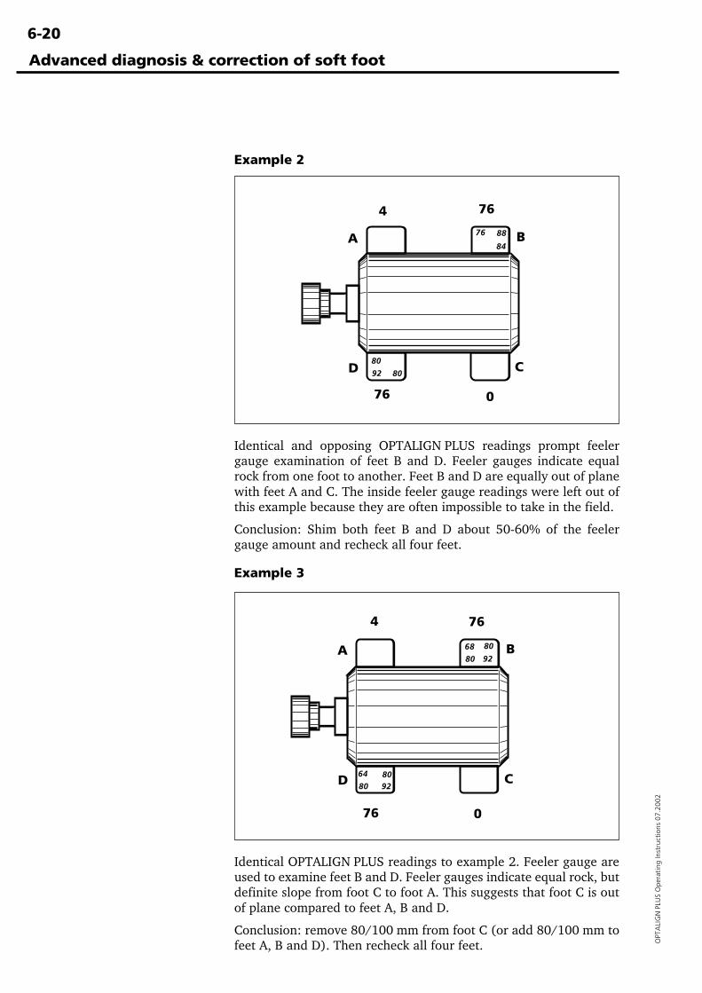
6-20
OPT
ALI
GN
PLU
S O
pera
ting
Inst
ruct
ions
07.
2002
Advanced diagnosis & correction of soft foot
Example 2
Identical and opposing OPTALIGN PLUS readings prompt feelergauge examination of feet B and D. Feeler gauges indicate equalrock from one foot to another. Feet B and D are equally out of planewith feet A and C. The inside feeler gauge readings were left out ofthis example because they are often impossible to take in the field.
Conclusion: Shim both feet B and D about 50-60% of the feelergauge amount and recheck all four feet.
Identical OPTALIGN PLUS readings to example 2. Feeler gauge areused to examine feet B and D. Feeler gauges indicate equal rock, butdefinite slope from foot C to foot A. This suggests that foot C is outof plane compared to feet A, B and D.
Conclusion: remove 80/100 mm from foot C (or add 80/100 mm tofeet A, B and D). Then recheck all four feet.
Example 3
80
92 80
76
84
88
4 76
076
80
64
80
68
80 92
8092
76 0
764
CD
A B
CD
A B
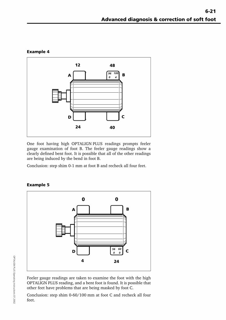
6-21
OPTA
LIGN
PLUS O
perating Instructions 07.2002
Advanced diagnosis & correction of soft foot
One foot having high OPTALIGN PLUS readings prompts feelergauge examination of foot B. The feeler gauge readings show aclearly defined bent foot. It is possible that all of the other readingsare being induced by the bend in foot B.
Conclusion: step shim 0-1 mm at foot B and recheck all four feet.
Feeler gauge readings are taken to examine the foot with the highOPTALIGN PLUS reading, and a bent foot is found. It is possible thatother feet have problems that are being masked by foot C.
Conclusion: step shim 0-60/100 mm at foot C and recheck all fourfeet.
Example 4
Example 5
100
496
24 40
12
0
48
244
56 600 0
0 0
CD
A B
CD
A B
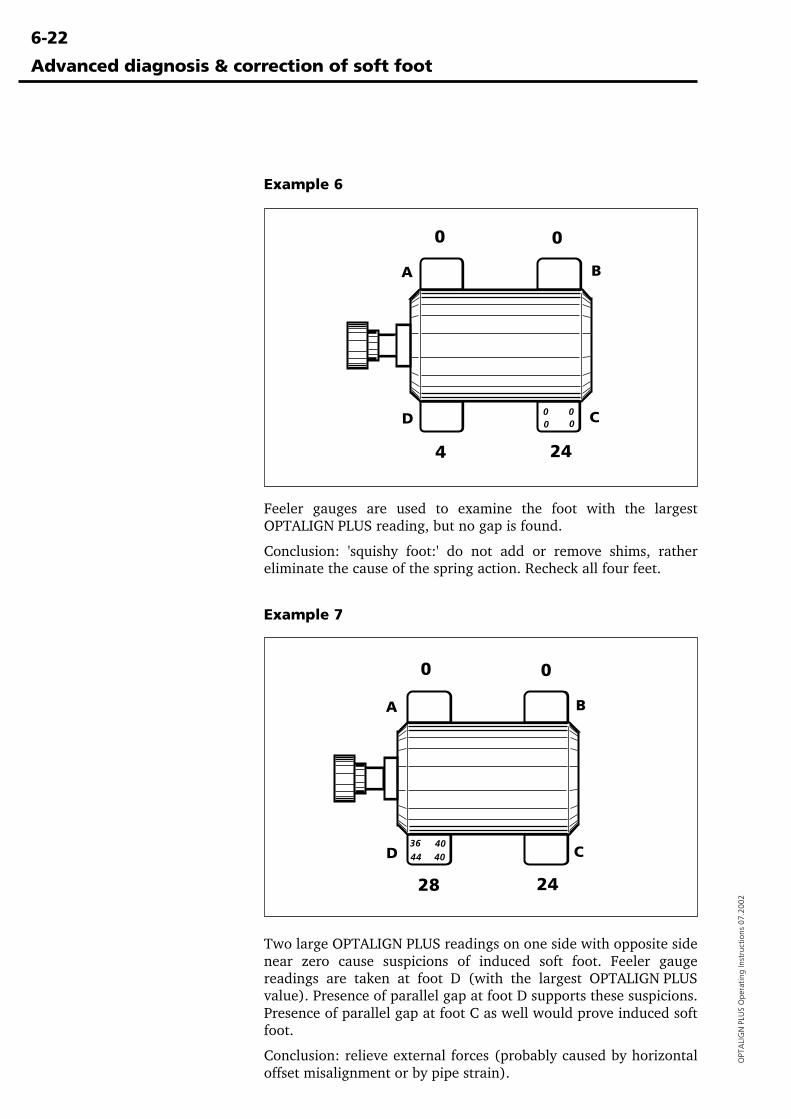
6-22
OPT
ALI
GN
PLU
S O
pera
ting
Inst
ruct
ions
07.
2002
Advanced diagnosis & correction of soft foot
Example 6
Two large OPTALIGN PLUS readings on one side with opposite sidenear zero cause suspicions of induced soft foot. Feeler gaugereadings are taken at foot D (with the largest OPTALIGN PLUSvalue). Presence of parallel gap at foot D supports these suspicions.Presence of parallel gap at foot C as well would prove induced softfoot.
Conclusion: relieve external forces (probably caused by horizontaloffset misalignment or by pipe strain).
Example 7
Feeler gauges are used to examine the foot with the largestOPTALIGN PLUS reading, but no gap is found.
Conclusion: 'squishy foot:' do not add or remove shims, rathereliminate the cause of the spring action. Recheck all four feet.
000
36
44
0
244
0 0
4040
28 24
00
CD
A B
CD
A B
6-23
OPTA
LIGN
PLUS O
perating Instructions 07.2002
Advanced diagnosis & correction of soft foot
Summary
When eliminating soft foot follow these steps:
1. Check all four feet of one machine with OPTALIGN PLUS. If anyof the feet shows over 8/100 mm (or 2 mils) proceed with step2, otherwise go to step 5.
2. Examine the largest (or two largest, if the same) soft foot withfeeler gauges to determine the type of soft foot. It never hurts toexamine the other feet as well, but concentrate on finding andfixing the largest single problem, one problem at a time.
3. Correct the condition diagnosed, usually by shimming only onefoot, if any.
4. Go to step 1.
5. If both machines have been checked for soft foot and are withintolerances, perform final alignment.
If the adjoining machine is set to 'movable' (page 4-29) then itcan also be checked for softfoot. Start again at step 1.
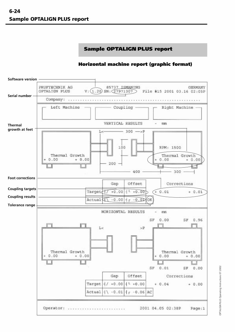
6-24
OPT
ALI
GN
PLU
S O
pera
ting
Inst
ruct
ions
07.
2002
Sample OPTALIGN PLUS report
Sample OPTALIGN PLUS report
Horizontal machine report (graphic format)
Software version
Serial number
Coupling targets
Thermalgrowth at feet
Coupling results
Foot corrections
Tolerance range
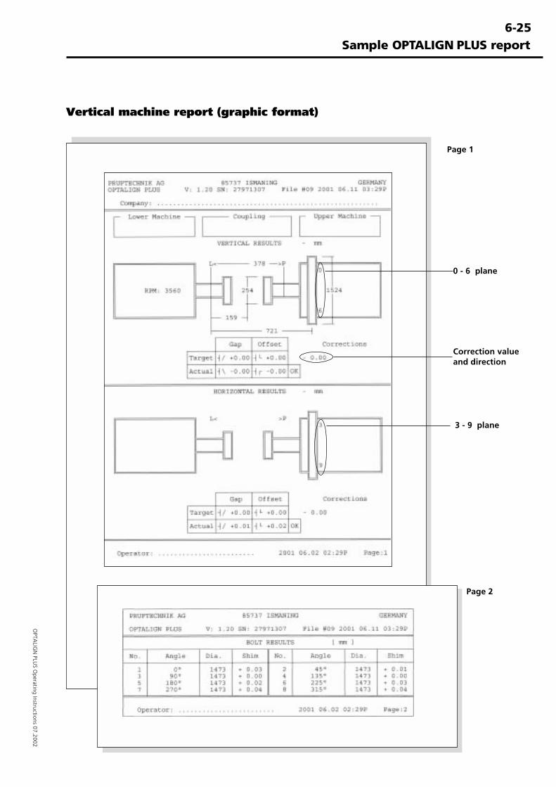
6-25
OPTA
LIGN
PLUS O
perating Instructions 07.2002
Sample OPTALIGN PLUS report
Vertical machine report (graphic format)
Page 2
Page 1
0 - 6 plane
3 - 9 plane
Correction valueand direction
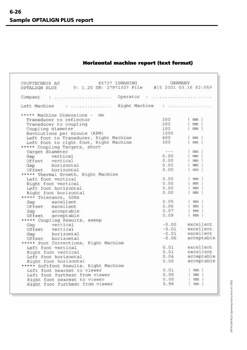
6-26
OPT
ALI
GN
PLU
S O
pera
ting
Inst
ruct
ions
07.
2002
Sample OPTALIGN PLUS report
Horizontal machine report (text format)
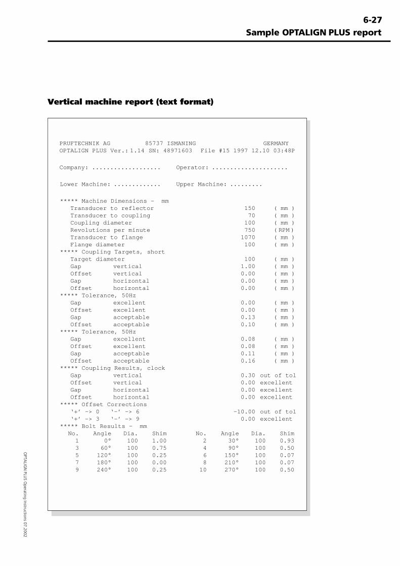
6-27
OPTA
LIGN
PLUS O
perating Instructions 07.2002
Sample OPTALIGN PLUS report
Vertical machine report (text format)
PRUFTECHNIK AG 85737 ISMANING GERMANYOPTALIGN PLUS Ver.: 1.14 SN: 48971603 File #15 1997 12.10 03:48P
Company: ................... Operator: .....................
Lower Machine: ............. Upper Machine: .........
***** Machine Dimensions - mmTransducer to reflector 150 ( mm )Transducer to coupling 70 ( mm )Coupling diameter 100 ( mm )Revolutions per minute 750 ( RPM )Transducer to flange 1070 ( mm )Flange diameter 100 ( mm )
***** Coupling Targets, shortTarget diameter 100 ( mm )Gap vertical 1.00 ( mm )Offset vertical 0.00 ( mm )Gap horizontal 0.00 ( mm )Offset horizontal 0.00 ( mm )
***** Tolerance, 50HzGap excellent 0.00 ( mm )Offset excellent 0.00 ( mm )Gap acceptable 0.13 ( mm )Offset acceptable 0.10 ( mm )
***** Tolerance, 50HzGap excellent 0.08 ( mm )Offset excellent 0.08 ( mm )Gap acceptable 0.11 ( mm )Offset acceptable 0.16 ( mm )
***** Coupling Results, clockGap vertical 0.30 out of tolOffset vertical 0.00 excellentGap horizontal 0.00 excellentOffset horizontal 0.00 excellent
***** Offset Corrections‘+’ -> 0 ‘-’ -> 6 -10.00 out of tol‘+’ -> 3 ‘-’ -> 9 0.00 excellent
***** Bolt Results - mmNo. Angle Dia. Shim No. Angle Dia. Shim
1 0° 100 1.00 2 30° 100 0.933 60° 100 0.75 4 90° 100 0.505 120° 100 0.25 6 150° 100 0.077 180° 100 0.00 8 210° 100 0.079 240° 100 0.25 10 270° 100 0.50
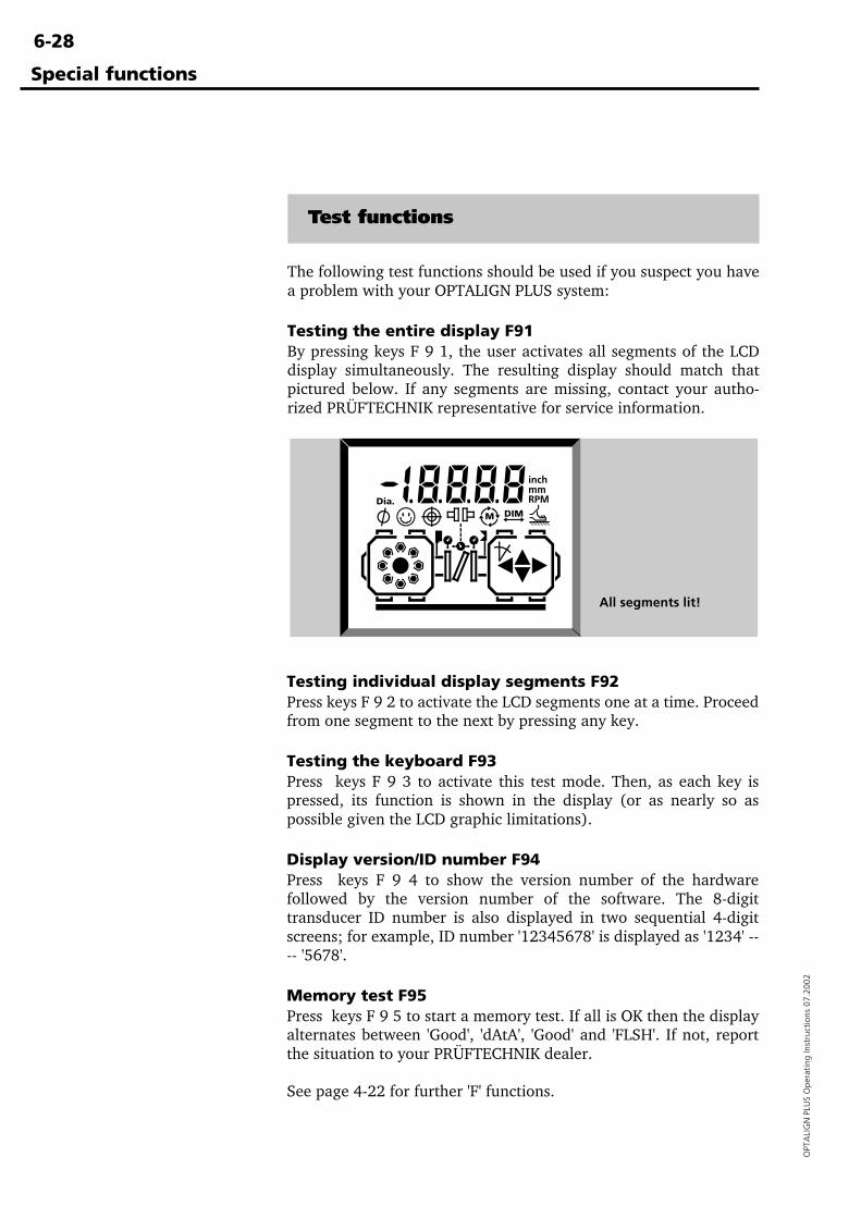
6-28
OPT
ALI
GN
PLU
S O
pera
ting
Inst
ruct
ions
07.
2002
Test functions
The following test functions should be used if you suspect you havea problem with your OPTALIGN PLUS system:
Testing the entire display F91By pressing keys F 9 1, the user activates all segments of the LCDdisplay simultaneously. The resulting display should match thatpictured below. If any segments are missing, contact your autho-rized PRÜFTECHNIK representative for service information.
Testing individual display segments F92Press keys F 9 2 to activate the LCD segments one at a time. Proceedfrom one segment to the next by pressing any key.
Testing the keyboard F93Press keys F 9 3 to activate this test mode. Then, as each key ispressed, its function is shown in the display (or as nearly so aspossible given the LCD graphic limitations).
Display version/ID number F94Press keys F 9 4 to show the version number of the hardwarefollowed by the version number of the software. The 8-digittransducer ID number is also displayed in two sequential 4-digitscreens; for example, ID number '12345678' is displayed as '1234' ---- '5678'.
Memory test F95Press keys F 9 5 to start a memory test. If all is OK then the displayalternates between 'Good', 'dAtA', 'Good' and 'FLSH'. If not, reportthe situation to your PRÜFTECHNIK dealer.
See page 4-22 for further 'F' functions.
Special functions
All segments lit!
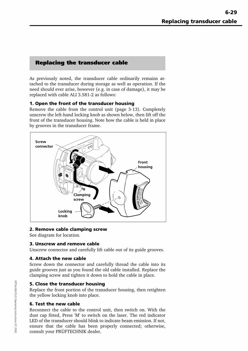
6-29
OPTA
LIGN
PLUS O
perating Instructions 07.2002
Replacing the transducer cable
As previously noted, the transducer cable ordinarily remains at-tached to the transducer during storage as well as operation. If theneed should ever arise, however (e.g. in case of damage), it may bereplaced with cable ALI 3.581-2 as follows:
1. Open the front of the transducer housingRemove the cable from the control unit (page 3-13). Completelyunscrew the left-hand locking knob as shown below, then lift off thefront of the transducer housing. Note how the cable is held in placeby grooves in the transducer frame.
2. Remove cable clamping screwSee diagram for location.
3. Unscrew and remove cableUnscrew connector and carefully lift cable out of its guide grooves.
4. Attach the new cableScrew down the connector and carefully thread the cable into itsguide grooves just as you found the old cable installed. Replace theclamping screw and tighten it down to hold the cable in place.
5. Close the transducer housingReplace the front portion of the transducer housing, then retightenthe yellow locking knob into place.
6. Test the new cableReconnect the cable to the control unit, then switch on. With thedust cap fitted, Press 'M' to switch on the laser. The red indicatorLED of the transducer should blink to indicate beam emission. If not,ensure that the cable has been properly connected; otherwise,consult your PRÜFTECHNIK dealer.
Replacing transducer cable
Lockingknob
Fronthousing
Clampingscrew
Screwconnector
6-30
OPT
ALI
GN
PLU
S O
pera
ting
Inst
ruct
ions
07.
2002
OPTALIGN PLUS Explorer and Editor
Alignment Explorer and Editor
The PC partner for OPTALIGN PLUS
The Alignment Explorer ( registered through a registration certifi-cate - ALI 5.250 ) and the OPTALIGN PLUS Editor ( registeredthrough a registration certificate - ALI 5.260 ) are the two mainprograms designed to help you archive and evaluate yourOPTALIGN PLUS measurement files.The description on the following pages covers software installa-tion, PC connection to the OPTALIGN PLUS control unit andtransfer of measurement files. For detailed description of thesoftware refer to the online help tools.
Please refer to the special note on page 1-9 regarding datastorage
System requirements
The following PC requirements must be met in order to ensurethat the program can operate as intended:
System Windows 95/ 98/ NT4 (SP5)/ 2000/ MEBrowser (online help) Internet Explorer 4 or laterProcessor Pentium, 100MHz or fasterMemory 32MB RAMHard disk 50MB availableCD-ROM drive for installationMonitor SVGA colorMouse with left and right click buttonsSerial interface RS232Printer any
Program overview
The Alignment Explorer transfers measurement data betweenOPTALIGN PLUS and PC. It uses 'drag & drop' to transport files toWord documents which could then easily be attached to E- mails.This program is a sort of 'File Manager', but without display andmanipulation capabilities.
To make full use of the Alignment Explorer and the OPTALIGNPLUS Editor, both software have to be registered.
A registered version of OPTALIGN PLUS Editor lets you makechanges to measurement files (which are non-cryptic) and isopened directly from the Alignment Explorer.
ID Number
To register the Alignment Explorer, the instrument ID No. isrequired. To obtain the ID No., connect the control unit to thetransducer and switch it on. Press the keys to displaythe ID number of the unit.
�Note
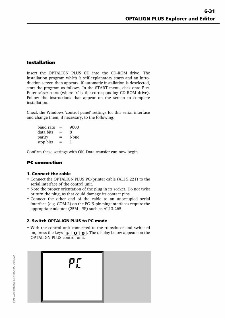
6-31
OPTA
LIGN
PLUS O
perating Instructions 07.2002
Installation
Insert the OPTALIGN PLUS CD into the CD-ROM drive. Theinstallation program which is self-explanatory starts and an intro-duction screen then appears. If automatic installation is deselected,start the program as follows. In the START menu, click onto RUN.Enter X:\START.EXE (where ‘x’ is the corresponding CD-ROM drive).Follow the instructions that appear on the screen to completeinstallation.
Check the Windows 'control panel' settings for this serial interfaceand change them, if necessary, to the following:
baud rate = 9600data bits = 8parity = Nonestop bits = 1
Confirm these settings with OK. Data transfer can now begin.
PC connection
1. Connect the cable• Connect the OPTALIGN PLUS PC/printer cable (ALI 5.221) to the
serial interface of the control unit.• Note the proper orientation of the plug in its socket. Do not twist
or turn the plug, as that could damage its contact pins.• Connect the other end of the cable to an unoccupied serial
interface (e.g. COM 2) on the PC. 9-pin plug interfaces require theappropriate adapter (25M - 9F) such as ALI 3.265.
2. Switch OPTALIGN PLUS to PC mode
• With the control unit connected to the transducer and switchedon, press the keys . The display below appears on theOPTALIGN PLUS control unit.
OPTALIGN PLUS Explorer and Editor
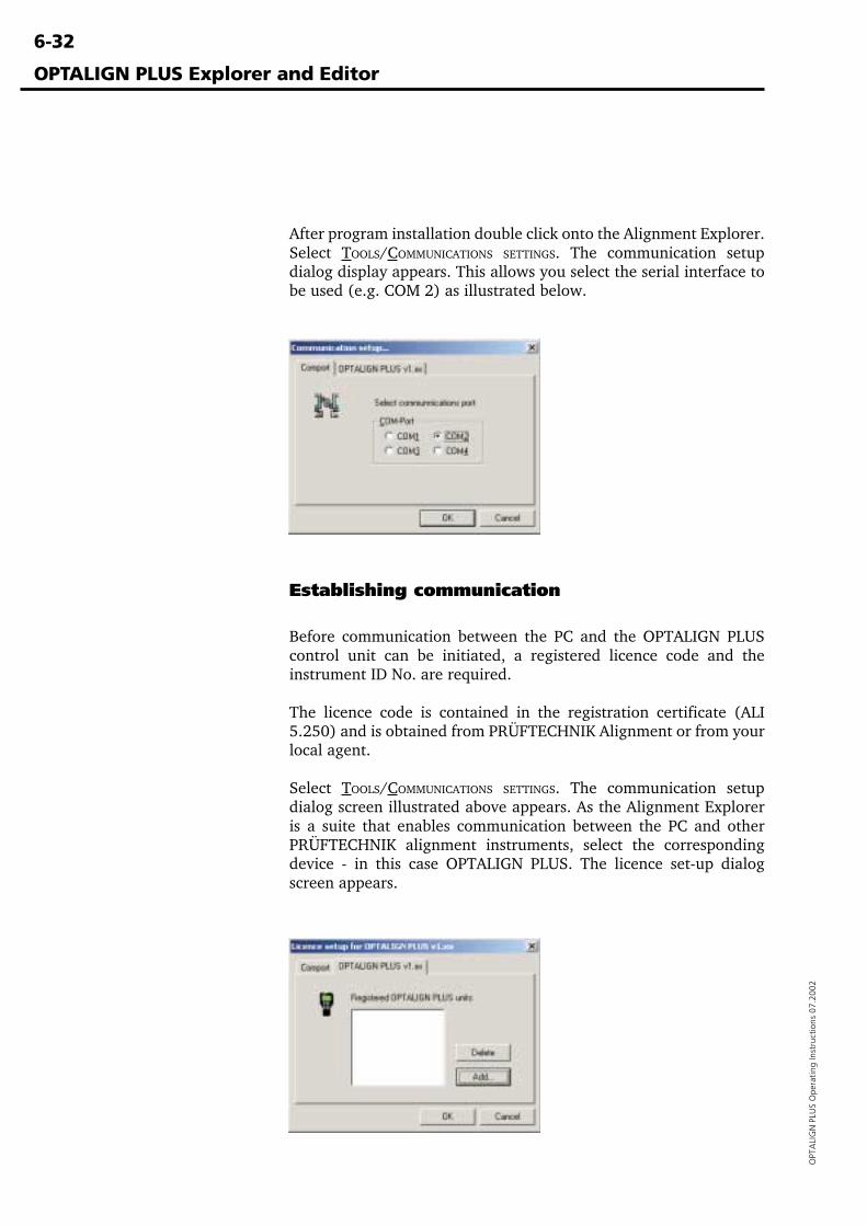
6-32
OPT
ALI
GN
PLU
S O
pera
ting
Inst
ruct
ions
07.
2002
After program installation double click onto the Alignment Explorer.Select TOOLS/COMMUNICATIONS SETTINGS. The communication setupdialog display appears. This allows you select the serial interface tobe used (e.g. COM 2) as illustrated below.
OPTALIGN PLUS Explorer and Editor
Establishing communication
Before communication between the PC and the OPTALIGN PLUScontrol unit can be initiated, a registered licence code and theinstrument ID No. are required.
The licence code is contained in the registration certificate (ALI5.250) and is obtained from PRÜFTECHNIK Alignment or from yourlocal agent.
Select TOOLS/COMMUNICATIONS SETTINGS. The communication setupdialog screen illustrated above appears. As the Alignment Exploreris a suite that enables communication between the PC and otherPRÜFTECHNIK alignment instruments, select the correspondingdevice - in this case OPTALIGN PLUS. The licence set-up dialogscreen appears.
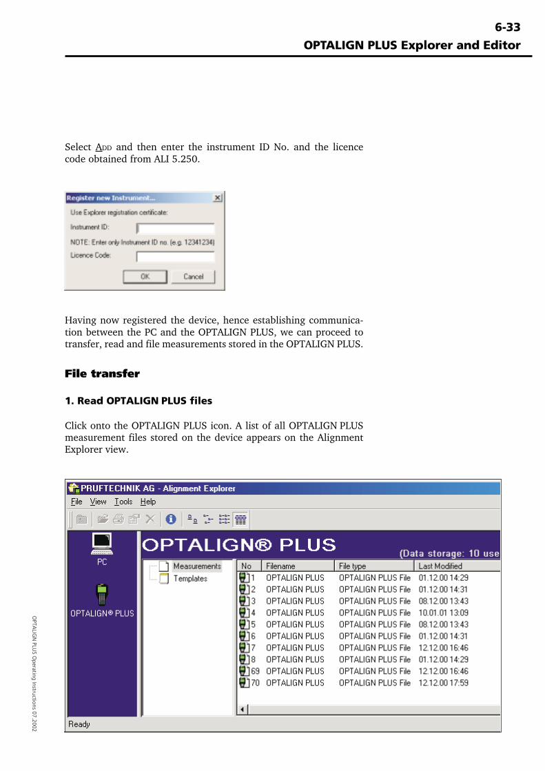
6-33
OPTA
LIGN
PLUS O
perating Instructions 07.2002
Select ADD and then enter the instrument ID No. and the licencecode obtained from ALI 5.250.
OPTALIGN PLUS Explorer and Editor
Having now registered the device, hence establishing communica-tion between the PC and the OPTALIGN PLUS, we can proceed totransfer, read and file measurements stored in the OPTALIGN PLUS.
File transfer
1. Read OPTALIGN PLUS files
Click onto the OPTALIGN PLUS icon. A list of all OPTALIGN PLUSmeasurement files stored on the device appears on the AlignmentExplorer view.
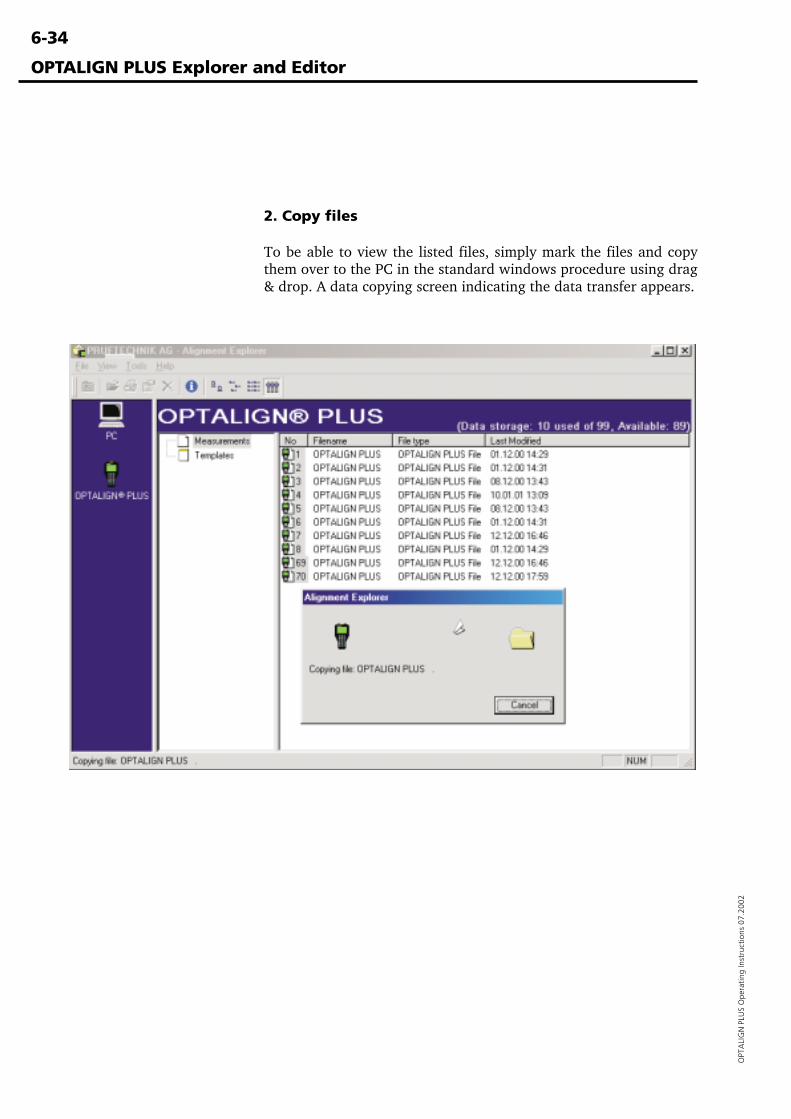
6-34
OPT
ALI
GN
PLU
S O
pera
ting
Inst
ruct
ions
07.
2002
OPTALIGN PLUS Explorer and Editor
2. Copy files
To be able to view the listed files, simply mark the files and copythem over to the PC in the standard windows procedure using drag& drop. A data copying screen indicating the data transfer appears.
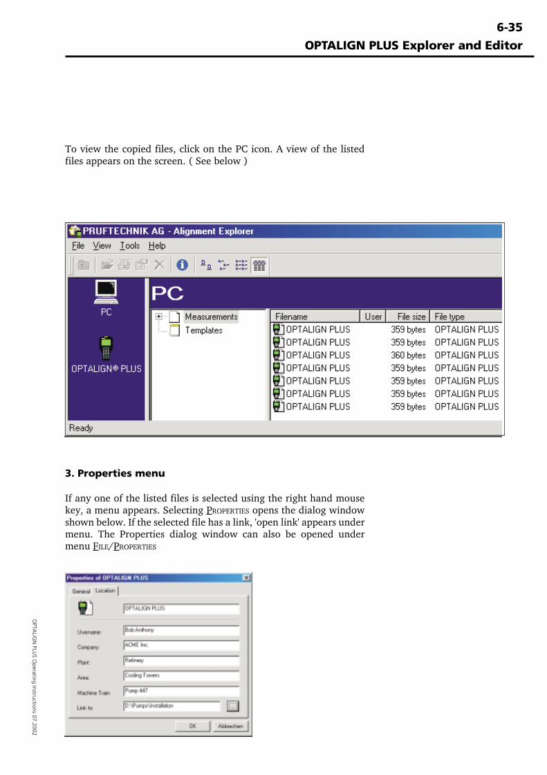
6-35
OPTA
LIGN
PLUS O
perating Instructions 07.2002
OPTALIGN PLUS Explorer and Editor
To view the copied files, click on the PC icon. A view of the listedfiles appears on the screen. ( See below )
3. Properties menu
If any one of the listed files is selected using the right hand mousekey, a menu appears. Selecting PROPERTIES opens the dialog windowshown below. If the selected file has a link, 'open link' appears undermenu. The Properties dialog window can also be opened undermenu FILE/PROPERTIES
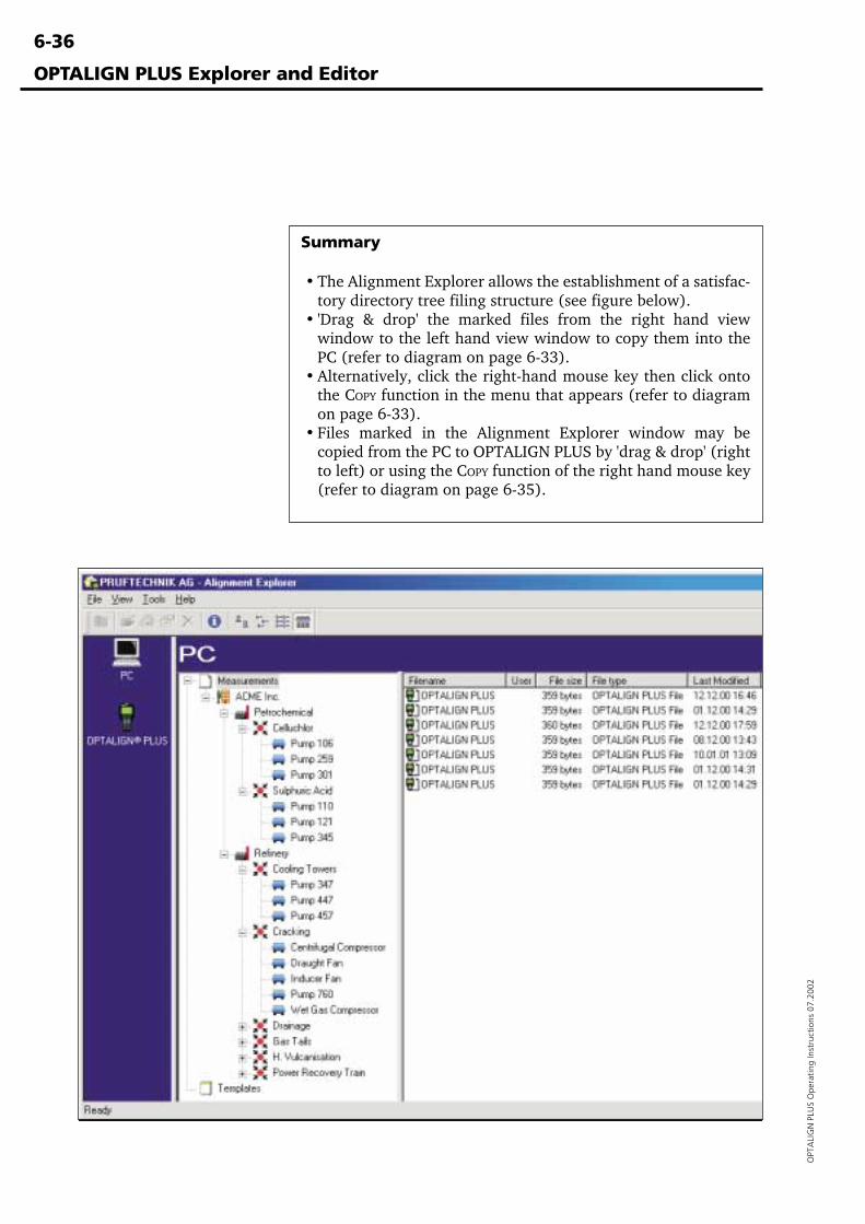
6-36
OPT
ALI
GN
PLU
S O
pera
ting
Inst
ruct
ions
07.
2002
Summary
• The Alignment Explorer allows the establishment of a satisfac-tory directory tree filing structure (see figure below).
• 'Drag & drop' the marked files from the right hand viewwindow to the left hand view window to copy them into thePC (refer to diagram on page 6-33).
• Alternatively, click the right-hand mouse key then click ontothe COPY function in the menu that appears (refer to diagramon page 6-33).
• Files marked in the Alignment Explorer window may becopied from the PC to OPTALIGN PLUS by 'drag & drop' (rightto left) or using the COPY function of the right hand mouse key(refer to diagram on page 6-35).
OPTALIGN PLUS Explorer and Editor
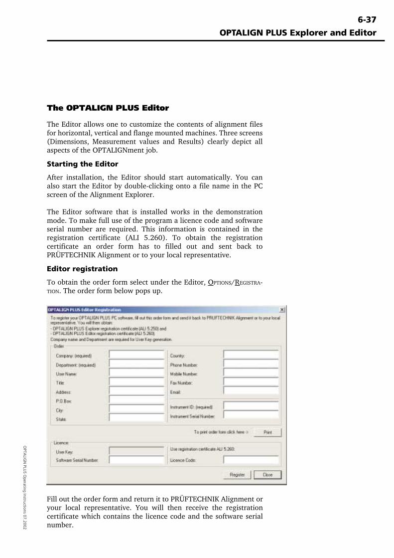
6-37
OPTA
LIGN
PLUS O
perating Instructions 07.2002
The OPTALIGN PLUS Editor
The Editor allows one to customize the contents of alignment filesfor horizontal, vertical and flange mounted machines. Three screens(Dimensions, Measurement values and Results) clearly depict allaspects of the OPTALIGNment job.
Starting the Editor
After installation, the Editor should start automatically. You canalso start the Editor by double-clicking onto a file name in the PCscreen of the Alignment Explorer.
The Editor software that is installed works in the demonstrationmode. To make full use of the program a licence code and softwareserial number are required. This information is contained in theregistration certificate (ALI 5.260). To obtain the registrationcertificate an order form has to filled out and sent back toPRÜFTECHNIK Alignment or to your local representative.
Editor registration
To obtain the order form select under the Editor, OPTIONS/REGISTRA-TION. The order form below pops up.
OPTALIGN PLUS Explorer and Editor
Fill out the order form and return it to PRÜFTECHNIK Alignment oryour local representative. You will then receive the registrationcertificate which contains the licence code and the software serialnumber.
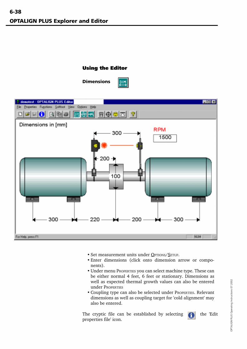
6-38
OPT
ALI
GN
PLU
S O
pera
ting
Inst
ruct
ions
07.
2002
• Set measurement units under OPTIONS/SETUP.• Enter dimensions (click onto dimension arrow or compo-
nents).• Under menu PROPERTIES you can select machine type. These can
be either normal 4 feet, 6 feet or stationary. Dimensions aswell as expected thermal growth values can also be enteredunder PROPERTIES
• Coupling type can also be selected under PROPERTIES. Relevantdimensions as well as coupling target for 'cold alignment' mayalso be entered.
The cryptic file can be established by selecting the 'Editproperties file' icon.
Using the Editor
Dimensions
OPTALIGN PLUS Explorer and Editor
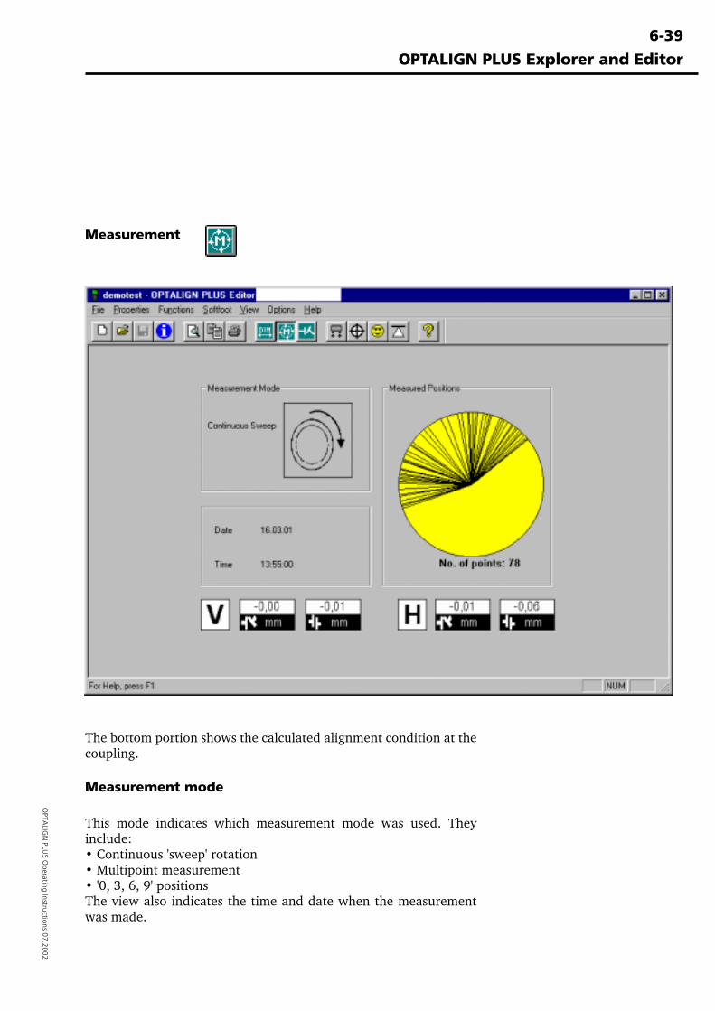
6-39
OPTA
LIGN
PLUS O
perating Instructions 07.2002
Measurement
The bottom portion shows the calculated alignment condition at thecoupling.
Measurement mode
This mode indicates which measurement mode was used. Theyinclude:• Continuous 'sweep' rotation• Multipoint measurement• '0, 3, 6, 9' positionsThe view also indicates the time and date when the measurementwas made.
OPTALIGN PLUS Explorer and Editor
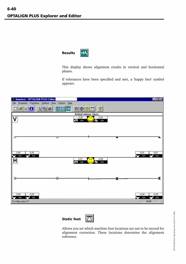
6-40
OPT
ALI
GN
PLU
S O
pera
ting
Inst
ruct
ions
07.
2002
Results
This display shows alignment results in vertical and horizontalplanes.
If tolerances have been specified and met, a 'happy face' symbolappears.
OPTALIGN PLUS Explorer and Editor
Static feet
Allows you set which machine foot locations are not to be moved foralignment correction. These locations determine the alignmentreference.
6-41
OPTA
LIGN
PLUS O
perating Instructions 07.2002
Troubleshooting checklist
Troubleshooting checklist
OPTALIGN PLUS is designed to withstand a rough industrialoperating environment. Should you nonetheless encounter difficul-ty someday, the following checklist of possible problems can be agreat help in locating and eliminating the source of trouble.
Following each entry is a number indicating the effect of thatproblem on measurements:[1] no influence on measurement accuracy and repeatability[2] measurement accuracy affected[3] repeatability affected
1. Loose brackets can lead to erroneous results. Check to make surethey fit tightly on the shafts (see page 3-8 for correct mountingprocedure). [2, 3]
2. Severe torsion or coupling backlash may affect measurement (seepage 6-7). However, OPTALIGN PLUS measurements normallyremain unaffected by up to 5° of backlash. [2, 3]
3. Measurement interference due to vibration from adjacent ma-chinery is nearly unheard of; changing X,Y coordinate values in thedisplay would be the result. [1]
4. Axial shaft play does not influence measurement results to anyappreciable degree. [1]
5. If neglected, thermal growth effects can result in unexpectedalignment changes as the machine warms up during operation (seepage 4-16). There will be a loss of repeatability if the alignment ischanging while taking a set of readings. This is especially prevalentin a rapid cool-down of a machine immediately after shutdown. [3]
6. Temperature changes can temporarily affect the OPTALIGN PLUS(for example, if the unit is stored in a cool area, then brought into ahot, humid work area, the optics can fog over and the housing mayexpand slightly). Remedy: allow the OPTALIGN PLUS componentsto reach ambient air temperature before taking measurements. [2,3]
7. The electronic components used in the transducer may betemporarily affected by excessive temperatures, so protect thesystem from extended exposure to high temperatures and observethe operating temperature range of 0° C to 55° C (32° F to 131° F).[2, 3]
8. In a few rare cases, powerful infrared light sources, welding arcsand direct sunlight can overload the detector. The display will thenshow 'Err,' and measurements cannot be taken until the infrareddisturbance is eliminated (simply by shading the transducer). [1]
9. Steam, dust particles, soot suspended in the air, etc. can block thelaser beam. When the detector no longer receives the beam, it
6-42
OPT
ALI
GN
PLU
S O
pera
ting
Inst
ruct
ions
07.
2002
Troubleshooting checklist
causes the display to show 'OFF.' But over the relatively shortseparations involved, this is a rare occurrence. The situation can beeasily remedied by shielding the beam from blockage, best done byholding a tube between (but not touching) the transducer andreflector through which the beam then passes each time readingsare taken. [1]
10. With OPTALIGN PLUS, bracket sag is non-existent. [1]
11. Low battery level does not influence measurement accuracy. Asthe batteries become depleted, the display flashes a 'battery low'message. The user can then switch over to reserve (AUX) batterypower to finish the job at hand before replacing batteries. [1]
12. If the machine housing is placed under stress, e.g. by loads fromintake/discharge piping or flimsy shafts, loose bearings or othermachine defects, OPTALIGN PLUS will still measure displacementsin exactly the same manner as always, but all of these defectsintroduce highly unpredictable (and hence often unrepeatable)shaft displacements during measurement. These factors shouldtherefore be checked before taking measurements to save time andfrustration later. [3]
Summary
The exceptionally precise measurement of relative movementsbetween transducer and reflector are converted directly into offsetsat the coupling and machine feet. Four conditions must be fulfilledfor this principle to deliver correct alignment recommendations:
1. The transducer and reflector must be mounted rigidly on theshafts (or coupling flanges) and may not slip or twist duringmeasurement.
2. The machine shafts must be rigid. No elastic deformation canoccur during rotation.
3. The shafts must rotate about their own operating axes duringmeasurement. Any displacement from this position must be con-stant and predictable so that it may be compensated. The shaftsmust not trace an elliptical path as they rotate.
4. Soft foot or machine base instability must be checked andcorrected before alignment.
In the vast majority of cases, OPTALIGN PLUS measurements whichat first may appear to be unreliable or inaccurate can be traced backto some violation of one of these four rules.
6-43
OPTA
LIGN
PLUS O
perating Instructions 07.2002
Warranty, service and care
WarrantyThe OPTALIGN PLUS laser diode is guaranteed for two years. Allother system components are covered by a one-year warranty.Please note that any attempt to service the components by unautho-rized personnel will render all warranty coverage void.
Service and careOPTALIGN PLUS is a precision measurement instrument whichshould be handled as such. When not in use, it should always bestored in its protective carrying case.
Although the OPTALIGN PLUS system is essentially maintenance-free, the following points should be observed: The calibrationaccuracy of the system should be checked every two years asindicated by the colored label located at the back of the transducerhousing. Please return OPTALIGN PLUS to your authorizedPRÜFTECHNIK distributor for calibration checking.
All optical surfaces (transducer lens, reflector) must be kept clean.Use the ALI 2.905 cleaning set or a fine dusting brush such as thatnormally used to clean other optical devices; avoid vigorouspolishing to preserve the anti-reflective coatings of the glasselements. The computer housing may be wiped clean using a softcloth dampened with a mild, nonabrasive detergent.
If any problems are encountered during use, consult the trouble-shooting guide on the previous page for help in locating andcorrecting the problem. (In particular, check the cable connectionbetween transducer and computer first for signs of damage.) If theproblem still cannot be resolved, then contact your PRÜFTECHNIKAG representative for further assistance.
Maintenance may be carried out only by trained personnel.
OPTALIGN PLUS Upgrade Package ALI 5.225setThe operating software ('firmware') of the OPTALIGN PLUS systemcan be functionally enhanced as newer versions become available:an easy-to-use PC program allows the user to upgrade the firmwarein a matter of minutes. (The version number of the firmwareappears in the OPTALIGN PLUS display when first switched on.)
Spare parts, accessoriesOnly original spare parts and accessories may be used. Pleaseconsult the Alignment Product Catalog (ALI 9.300) for completedetails.
DisposalBatteries, the OPTALIGN PLUS components and accessories are tobe disposed of in accordance with applicable environmental regula-tions at the end of their operating lives.
Warranty, service and care
6-44
OPT
ALI
GN
PLU
S O
pera
ting
Inst
ruct
ions
07.
2002
Error messages
OPTALIGN PLUS self-diagnostic routines enable the control unit todisplay the following messages which indicate the exact source oferror. The corresponding remedies are listed below.
Symbol
''Transducer' blinks Transducer not connected.
'BATT.' blinks Depleted batteries should be replaced(see page 2-7).
Text
''Abnt' Excessive ambient light: shade the receiver.
'n.Lin' Linearization data is corrupted or missing:Return the transducer and control unit forrepair.
'in.Er' Inclinometer faulty. Return transducer for re-pair.
'End' Laser beam is outside of linearized measure-ment range of position detector. Use F6 toreadjust the laser (see pages 3-19, 4-27).
'Off' Laser beam misses detector completely. UseF6 to readjust the laser (see pages 3-19, 4-27).
'The following errors can occur during file loading (page 3-34):
'Er.--' Error of unknown origin
'Er.01' No file found under the number entered
'Er.02' Check sum error (file data corrupt)
'Er.03' Data set missing (e.g. left machine or specs)
'Er.04' Error copying file to working file slot #0 (page3-34)
The following errors can occur during file storage (page 3-33):
'Er.--' Error of unknown origin
'Er.05' Memory card faulty
'Er.06' No more storage space available
All of these file handling errors indicate serious problems in the filemanagement system. In that case, try reformatting the memory cardusing function F90. If this does not help, then the transducer andcontrol unit must be returned for repair.
Error messages
6-45
OPTA
LIGN
PLUS O
perating Instructions 07.2002
Technical data
OPTALIGN PLUS technical data
Transducer
Measurement principle Coaxial, reflected laser beam
Measurement types 2 axes (x,y); 1 inclination
Laser type Ga-Al-As semiconductor laser
Wavelength (typical) 670 nm ±10 nm (red, visible)
Environmentalprotection IP 67
Ambient lightprotection yes
Intrinsic safety (option) EEx ib IIC T4
Certificate number TÜV 01 ATEX 1730
Temperature storage -20°C - 80°C / -4°F - 176°F operating 0°C - 55°C / 32°F - 131°F
Dimensions approx. 107 x 70 x 49 mm4 1/4" x 2 3/4" x 2"
Weight: approx. 177g / 6½ oz.
Laser
Safety class Class 2; FDA 21CFR 1000 and 1040
Beam divergence < 0.3 mrad
Beam power < 1 mW
Beam diameter 7 mm
Safety precautions Do not look into laser beam
Detector
Measurement area unlimited, dynamically extendible
Resolution 1 µm
Accuracy better than 2%
Inclinometermeasurement range 0° - 360°resolution 2°
Reflector
Type 90° roof prism
Environmentalprotection IP 67
Accuracy Better than 1%
Temperaturestorage -20°C - 80°C / -4°F - 176°F
operating -20°C - 60°C / -4°F - 140°F
Dimensions: approx. 100 x 41 x 35 mm4" x 1 5/8" x 1 3/8"
Weight: approx. 65g / 2½ oz.
*Based upon an operating cycle of
25% measurement,
25% computation and
50% 'sleep' mode.
Control Unit
Display fixed-segment LCD display
Display dimensions approx. 94 x 73 mm / 3 3/4" x 2 7/8"
Keyboard robust flat keyboard
Environmentalprotection IP 65
Temperaturestorage -20°C - 80°C / -4°F - 176°Foperating 0°C - 55°C / 32°F - 131°F
Main power supply 6 x 1.5V IEC LR6 ("AA") batteries
Back-up power supply 1 x 9V IEC 6LR61 battery
Battery life (typical) 25 hours* on main batteries3 hours* on back-up battery
Interfaces 1 x sensor; 1 x printer/PC (serial)
Intrinsic safety (option) EEx ib IIC T4
Certificate number TÜV 01 ATEX 1730
Dimensions approx. 145 x 290 x 67 mm5 3/4" x 11 1/2" x 2 3/4"
Weight approx. 1.1 kg / 2.4 lb.
Carrying case
Standard Black plastic, lockable
Case dimensions Approx. 470 x 400 x 195 mm18 1/2" x 15 3/4" x 7 3/4"
Weight, includingall standard parts Approx. 6.8 kg / 15.2 lb.
6-46
OPT
ALI
GN
PLU
S O
pera
ting
Inst
ruct
ions
07.
2002
Index
Index
A
Accessory bracketscompact magnetic 6-14coupling bolt hole 6-15
ALI 5.250 6-30ALI 5.260 6-30Alignment
accuracy 6-4at the coupling 3-24Checking with vibration analysis 6-11correction 6-2, 3-26definition 6-2, 6-3, 6-4, 6-5further reading 6-8methods 6-3parameters 6-2preparation 6-6, 6-7, 6-8, 6-9Tolerances 6-5tolerances 6-5
Alignment Explorer 6-30Anchor peg 3-9Angularity 6-2Axial shaft play 6-41
B
backlash 6-7, 4-9Battery
back-up 2-9depletion 6-42main 2-8reserve 2-9
Beam deflector 2-13Bracket
Compact chain-type 2-13sag 6-42
Bracketsloose 6-41mounting 3-8
Brackets, accessory 6-12compact magnetic bracket 6-14coupling bolt hole bracket 6-15extra-thin bracket 6-13magnetic sliding bracket 6-12
C
Calibration 6-43CE conformance
Disposal 6-43Electromagnetic compatibility (EMC) 1-5Intended use 1-5Laser power 1-6
Operating considerations 1-8Interface connections 1-8Spare parts, accessories 1-8Temperature range 1-8Water and contamination resistance 1-9
Operationg considerationsOperating environment 1-8
Safety notes 1-6'Cold alignment' 4-17Communication
establishing 6-32set-up 6-32
Computer 2-3, 2-4, 2-5keyboard 2-4, 2-5screen 2-5switching on 3-14
Couplingalignment 3-24play 3-7
Coupling play 6-7Coupling targets 4-16Couplings 4-30
rigidtest 6-6
uncoupled 6-6Couplings, rigid 6-6
D
demo mode 6-37Dimensions 3-15display viewer
software 4-36training 4-36
Disposal 6-43'drag & drop' 6-30, 6-36
E
Electromagnetic compatibility (EMC) 1-5'END' 4-27'Err' 6-41Extending measurement range 4-27
6-47
OPTA
LIGN
PLUS O
perating Instructions 07.2002
Index
F
F Function'END/OFF' 4-28F71
report format 4-29F74
results default 4-32F80 select language 4-32F82 set average readings 4-33
F FunctionsF00 PC communication 4-35F08 overview 4-35F09 report languages 4-35F1
x,y coordinates 4-23F2
units 4-24F3
6-feet machine 4-24F4
time and date display 4-26F6
extend measurement 4-27F70
static feet 4-29F73
coupling type 4-30F78
diameter default 4-32F79
default rpm 4-32F80
date and time 4-32F83 set deviation band 4-33F84 set resolution 4-33F90 delete files 4-34F94 transducer sleep mode 4-34F98 reset factory defaults 4-34F99 new machine 4-34over view 4-22
filecryptic 6-38
File properties 6-35
H
Horizontal alignment 3-34Humidity 1-8
I
ID Numberinstrument 6-30
Inchesswitching to 3-15
Inclinometer 2-11Infrared light
interference from 6-41Intended use 1-5Interface
RS232/printer 2-6Interface connections 1-8Intrinsic safety 2-9, 1-6
K
Keyboardtest 6-28
L
labelling 1-10LAMIBLOC 6-2Laser
adjustment 3-18, 3-22beam blockage 6-41power 1-6safety 1-7
Laser safety 1-7licence code 6-32, 6-37
M
Machine dimensions 3-15entering 3-15
Machine preparation 6-6, 6-8Coupling play 6-7foundation 6-6mobility 6-6Rigid couplings 6-6Shaft play 6-7Soft foot 6-8
Machine preparation 4 3-7Measurement
principle 6-11Measurement mode
continuous sweep 4-8multipoint 4-10static (0,3,6,9) 4-12
measurement principle 6-11
6-48
OPT
ALI
GN
PLU
S O
pera
ting
Inst
ruct
ions
07.
2002
Memory 2-10electronic 2-10transducer 2-11
MOVE 3-30MOVE function 3-30
N
NumberingCoupling housing 5 5-6Shaft 5 5-5
O
Offset 6-2Operating environment 1-8OPTALIGN PLUS
Computer 2-3at a glance 2-4
computer 2-4measurement principle 6-11package 1-2, 1-3
OPTALIGN PLUS Editor 6-30, 6-37order form 6-37
P
PCcable connection 6-31connection 6-31data transfer 6-34requirement 6-30system requirement 6-30
PERMABLOC 6-2Play
coupling backlash 3-7position detector 2-11Power-saving features 2-10Preparation, Machine 6-6Prism
adjusting 3-18mounting 3-10
R
Reflector 2-12Registration certificate
ALI 5.250 6-30ALI 5.260 6-30
registration certificate 6-30Repeatability 6-42
Reportsample 6-24
Rigid couplings 6-6RS232/printer interface 2-6
S
Safety notes 1-6Serial/parallel converter 2-14Service 6-43Shaft
non-rotatable 4-14Shims 6-2, 6-9
stepped 4-7Sign convention 4-18, 4-21Soft foot 6-8, 4-2, 3-7
advanced diagnosis 6-18advanced diagnosis/correction 6-18angular 4-3, 4-7corrections 4-6determining corrections 4-6examples 6-19parallel 4-3procedure 4-4
Softwareinstallation 6-31
spacer shaft 4-30Spare parts, accessories 1-8Special functions 6-29Switching on computer 3-14
T
Technical data 6-45Temperature 6-41, 6-43
changes 6-41excessive 6-41
Temperature range 1-8Thermal growth 6-41, 4-16Transducer 2-11
cable replacement 6-29connecting 3-13connection 2-6mounting 3-10
Troubleshooting 6-41
Index

6-49
OPTA
LIGN
PLUS O
perating Instructions 07.2002
U
Uncoupled shafts 6-7
V
Vertical machine alignmenthorizontal correction 5-16procedure 5-6
Vibration 6-41influence on results 6-41
Vibration analysis 6-11vibration analysis 6-11
W
Warranty 6-43, 6-44Water and contamination resistance 1-9Windows
settings 6-31

6-50
OPT
ALI
GN
PLU
S O
pera
ting
Inst
ruct
ions
07.
2002
PRÜFTECHNIK Alignment SystemsP.O. Box 12 6385730 Ismaningwww.pruftechnik.comTel. +49 (0)89-99616-0Fax +49 (0)89-99616-200eMail: [email protected]
Productive maintenance technology
Printed in Germany ALI 9.560.07.02.08G
OPTALIGN®, VIBROTIP®, VIBROSPECT®, PERMABLOC® and LAMIBLOC®
are registered trademarks of PRÜFTECHNIK Dieter Busch AG. PRÜFTECH-NIK products are the subject of patents granted and pending throughoutthe world. Contents subject to change without further notice, particularlyin the interest of further technical development. Reproduction, in anyform whatsoever, only upon express written consent of PRÜFTECHNIK.© Copyright 1997 by PRÜFTECHNIK AG
Be sure to visit our Internet homepage for infoon new products, accessories and applications!
www.pruftechnik.com