Embed Size (px)
Citation preview

O P E R AT O R ’ S S A F E T Y A N D S E R V I C E M A N U A L
MBW, Inc.250 Hartford Rd • PO Box 440Slinger, WI 53086-0440Phone: (262) 644-5234Fax: (262) 644-5169Email: [email protected]: www.mbw.com
MBW (UK) Ltd.Units 2 & 3Cochrane StreetBolton BL3 6BN, EnglandPhone: 01204 387784Fax: 01204 387797
MBW France S.A.R.LPhone: +33 (0) 3 44 07 15 96Fax: +33 (0) 3 44 07 41 28
L21237.02.17.A©MBW, Inc. 2015Printed in the USA
F 3 6F 4 6This manual covers the following serial numbers and higher, for each model listed:
F36 . . . . . . . . . . . . . . . . . . . . . . 3620001.
F46 . . . . . . . . . . . . . . . . . . . . . . 4620001.
W A L K - B E H I N D T R O W E L S
TA B L E O F C O N T E N T S
SAFETY INFORMATION . . . . . . . . . . . . . . . . . 1
Introduction . . . . . . . . . . . . . . . . . . . . . . . . . . . . . . . . . 1
Safety Precautions . . . . . . . . . . . . . . . . . . . . . . . . . . . 1
Safety Decals . . . . . . . . . . . . . . . . . . . . . . . . . . . . . . . 1
Safety Decals - Constant Force Pitch Handle . . . . . . 3
SPECIFICATIONS. . . . . . . . . . . . . . . . . . . . . . . 4
OPERATION . . . . . . . . . . . . . . . . . . . . . . . . . . . 5
Introduction . . . . . . . . . . . . . . . . . . . . . . . . . . . . . . . . . 5
Before Starting & Operating . . . . . . . . . . . . . . . . . . . . 5
Starting Engine . . . . . . . . . . . . . . . . . . . . . . . . . . . . . . 5
Operating . . . . . . . . . . . . . . . . . . . . . . . . . . . . . . . . . . 5
Blade Pitch Adjustment (Standard). . . . . . . . . . . . . . . 5
Blade Pitch Adjustment (Constant Force). . . . . . . . . . 5
Handle Bar Adjustment. . . . . . . . . . . . . . . . . . . . . . . . 5
Stopping Engine . . . . . . . . . . . . . . . . . . . . . . . . . . . . . 6
MAINTENANCE . . . . . . . . . . . . . . . . . . . . . . . . 7
Maintenance Schedule . . . . . . . . . . . . . . . . . . . . . . . . 7
Fluid Levels. . . . . . . . . . . . . . . . . . . . . . . . . . . . . . . . . 7
Engine Maintenance . . . . . . . . . . . . . . . . . . . . . . . . . . 7
Engine Oil . . . . . . . . . . . . . . . . . . . . . . . . . . . . . . . . . . 7
Engine Speed . . . . . . . . . . . . . . . . . . . . . . . . . . . . . . . 7
Cleaning . . . . . . . . . . . . . . . . . . . . . . . . . . . . . . . . . . . 7
Lubrication . . . . . . . . . . . . . . . . . . . . . . . . . . . . . . . . . 7
Lifting . . . . . . . . . . . . . . . . . . . . . . . . . . . . . . . . . . . . . 8
Storage. . . . . . . . . . . . . . . . . . . . . . . . . . . . . . . . . . . . 8
Changing Trowel Blades . . . . . . . . . . . . . . . . . . . . . . 8
Setting Safety Switch . . . . . . . . . . . . . . . . . . . . . . . . . 8
Setting Tilt Arm Carriage Bolt Height . . . . . . . . . . . . . 8
SERVICE . . . . . . . . . . . . . . . . . . . . . . . . . . . . . . 9
Torque Chart . . . . . . . . . . . . . . . . . . . . . . . . . . . . . . . 9
Service Tools . . . . . . . . . . . . . . . . . . . . . . . . . . . . . . . 9
Gearbox Disassembly . . . . . . . . . . . . . . . . . . . . . . . . 9
Gearbox Assembly . . . . . . . . . . . . . . . . . . . . . . . . . . . 9
CFP Handle Cable/Spring Replacement . . . . . . . . . 10
Standard Handle Pitch Cable Replacement. . . . . . . 11
Shorting Wire Replacement . . . . . . . . . . . . . . . . . . . 11
Spider Bushing Removal . . . . . . . . . . . . . . . . . . . . . 11
Spider Bushing Replacement. . . . . . . . . . . . . . . . . . 12
Parts Replacement Cycles and Tolerances . . . . . . . 12
REPLACEMENT PARTS. . . . . . . . . . . . . . . . . 13
Gearbox Assembly . . . . . . . . . . . . . . . . . . . . . . . . . . 14
Spider Assembly . . . . . . . . . . . . . . . . . . . . . . . . . . . 16
Drive Assembly . . . . . . . . . . . . . . . . . . . . . . . . . . . . 18
Guard Assembly. . . . . . . . . . . . . . . . . . . . . . . . . . . . 20
Low Vibration Handle . . . . . . . . . . . . . . . . . . . . . . . . 22
Constant Force Handle Assembly . . . . . . . . . . . . . . 24
WARRANTY . . . . . . . . . . . . . . . . . . . . . . . . . . 26

CALIFORNIA PROPOSITION 65 WARNINGEngine exhaust and some of its constituents are known in the state of California to cause cancer,
birth defects, and other reproductive harm.
WARNING
- 1 -
S A F E T Y I N F O R M AT I O N
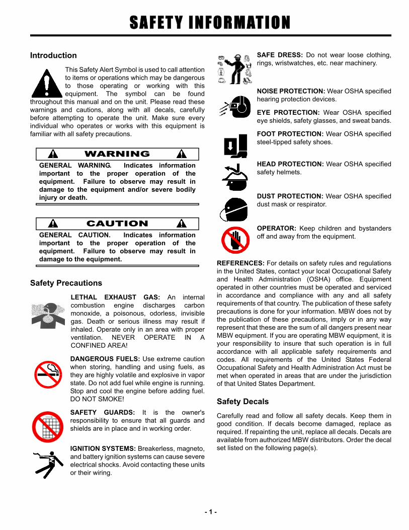
Introduction
This Safety Alert Symbol is used to call attentionto items or operations which may be dangerousto those operating or working with thisequipment. The symbol can be found
throughout this manual and on the unit. Please read thesewarnings and cautions, along with all decals, carefullybefore attempting to operate the unit. Make sure everyindividual who operates or works with this equipment isfamiliar with all safety precautions.
WARNINGGENERAL WARNING. Indicates informationimportant to the proper operation of theequipment. Failure to observe may result indamage to the equipment and/or severe bodilyinjury or death.
CAUTIONGENERAL CAUTION. Indicates informationimportant to the proper operation of theequipment. Failure to observe may result indamage to the equipment.
Safety Precautions
LETHAL EXHAUST GAS: An internalcombustion engine discharges carbonmonoxide, a poisonous, odorless, invisiblegas. Death or serious illness may result ifinhaled. Operate only in an area with properventilation. NEVER OPERATE IN ACONFINED AREA!
DANGEROUS FUELS: Use extreme cautionwhen storing, handling and using fuels, asthey are highly volatile and explosive in vaporstate. Do not add fuel while engine is running.Stop and cool the engine before adding fuel.DO NOT SMOKE!
SAFETY GUARDS: It is the owner'sresponsibility to ensure that all guards andshields are in place and in working order.
IGNITION SYSTEMS: Breakerless, magneto,and battery ignition systems can cause severeelectrical shocks. Avoid contacting these unitsor their wiring.
SAFE DRESS: Do not wear loose clothing,rings, wristwatches, etc. near machinery.
NOISE PROTECTION: Wear OSHA specifiedhearing protection devices.
EYE PROTECTION: Wear OSHA specifiedeye shields, safety glasses, and sweat bands.
FOOT PROTECTION: Wear OSHA specifiedsteel-tipped safety shoes.
HEAD PROTECTION: Wear OSHA specifiedsafety helmets.
DUST PROTECTION: Wear OSHA specifieddust mask or respirator.
OPERATOR: Keep children and bystandersoff and away from the equipment.
REFERENCES: For details on safety rules and regulationsin the United States, contact your local Occupational Safetyand Health Administration (OSHA) office. Equipmentoperated in other countries must be operated and servicedin accordance and compliance with any and all safetyrequirements of that country. The publication of these safetyprecautions is done for your information. MBW does not bythe publication of these precautions, imply or in any wayrepresent that these are the sum of all dangers present nearMBW equipment. If you are operating MBW equipment, it isyour responsibility to insure that such operation is in fullaccordance with all applicable safety requirements andcodes. All requirements of the United States FederalOccupational Safety and Health Administration Act must bemet when operated in areas that are under the jurisdictionof that United States Department.
Safety Decals
Carefully read and follow all safety decals. Keep them ingood condition. If decals become damaged, replace asrequired. If repainting the unit, replace all decals. Decals areavailable from authorized MBW distributors. Order the decalset listed on the following page(s).

- 2 -
13483
CAUTION
Wear approved hearing protection, foot protection, eye protection and head protection.
STOP
Read the Operating Instructions before operating this piece of equipment.Keep unauthorized and untrained people away from this equipment.
ROTATING & MOVING PARTS! Make sure all guards and safety devices are in place.
Failure to comply could result in serious bodily injury.
SHUT OFF the motor before servic-ing or cleaning.
DO NOT RUN in an enclosed area. The engine produces carbon monoxide, a POISONOUS GAS.
PATENT PENDING01504
Safety Decals (Decal Kit #19975)
12265
01260
21192
2118819970
19961
13483
19971
12267
WARNING Start engine at idle only!NEVER place foot on guard ring.
12265R
UN
IDLE
M-B-W INC.P.O. Box 440, Slinger, WI 53086USA * ENGLAND
01260 OFF
ON
SAF
ETY
SWITCH
M B W P O W E R T R O W E L
WARNING
When lifting attach proper safety chains to hook.Approximate weightF46 Models:260 lbs. (118 kg)F36 Models: 209 lbs. (95 kg)
21188
OPERATING INSTRUCTIONS1. Check engine oil and trowel gearbox oil.
2. Open fuel valve, put engine switch on.
3. Put SAFETY SWITCH in ON position; set throttle to idle position.
4. Choke engine. A warm engine may not need to be choked.
5. Starting engine: Place one hand on trowel handle and other hand on engine starter rope. NEVER place foot on guard ring. Pull starter rope.
6. Open choke, allow engine to warm up at idle.
7. Position throttle for various operating conditions.
8. TO STOP: Return throttle to idle position, put safety switch to off position. Close fuel valve.
19970
ROTATING PARTS can crush and cut. Keep
hands away!19971
WARNING
�������
�����
������ ���������� ������
19791
WARNINGOPERATION OF THIS EQUIPMENT MAY CREATE SPARKS THAT CAN START FIRES AROUND DRY VEGETATION. A SPARK ARRESTER MAY BE REQUIRED. THE OPERATOR SHOULD CONTACT LOCAL FIRE AGENCIES FOR LAWS OR REGULATIONS RELATING TO FIRE PREVENTION
1979119962
POWER TROWEL
19962 - 36”19963 - 46”
12500
21080
21186
01504
M B W P O W E R T R O W E L
21371

- 3 -
16168CONSTANT FORCE PITCH
16167
WARNINGSpring under tension!
Consult manual before
attempting service.
19791
WARNINGOPERATION OF THIS EQUIPMENT MAY CREATE SPARKS THAT CAN START FIRES AROUND DRY VEGETATION. A SPARK ARRESTER MAY BE REQUIRED. THE OPERATOR SHOULD CONTACT LOCAL FIRE AGENCIES FOR LAWS OR REGULATIONS RELATING TO FIRE PREVENTION
Safety Decals - Constant Force Pitch Handle
16168CONSTANT FORCE PITCH
16167
WARNINGSpring under tension!
Consult manual before
attempting service.
16167Not includedwith decal kit
16167Not includedwith decal kit
19791Not includedwith decal kit
16168Not includedwith decal kit
16167Not includedwith decal kit

- 4 -
S P E C I F I C AT I O N S
Specifications subject to change without notice1. Noise levels are based on operating conditions and will vary with background noise
F36/4 - Blade F46/4 - BladeGuard Ring (Outside Diameter) 37-1/2 in (95 cm) 47-5/8 in (121 cm)
Blade Sweep Diameter 35.5” (90 cm) 46” (117 cm)
Blade Pitch 0 to 20Trowel Rotor Speed 70 - 135 rpm 70 - 135 rpm
Low-Vibration Handle Height (Min./Max.) 35.8” - 43.3” (91 - 110 cm)
Operating Overall Length 75” (191 cm) 80” (203 cm)
Gas Engines OptionsHonda GX160 (9.9 in3/163cc)
Honda GX270 (16.5 in3/270cc)
Honda GX270 (16.5 in3/270cc)
Honda GX390 (23.7 in3/389cc)
Engine Speed 3400 rpm 3400 rpm
Operating Weight183 lbs (83 kg) [GX160]209 lbs (95 kg) [GX270]
246 lbs (112 kg) [GX270]260 lbs (118 kg) [GX390]
Noise Level1 85 - 105 dBA 85 - 105 dBA
O P E R AT I O N
Introduction
MBW equipment is intended for use in very severeapplications. They are powered by four cycle engines andare available in different sizes and a selection of engines.
This parts manual contains only standard parts. Variationsof these parts as well as other special parts are not included.Contact your local MBW distributor for assistance inidentifying parts not included in this manual.
Before Starting & Operating
• REMEMBER! It is the owner’s responsibility tocommunicate information on the safe use and properoperation of this unit to the operators.
• Review ALL of the Safety Precautions listed on page 1 ofthis manual.
• Familiarize yourself with the operation of the machineand confirm that all controls function properly.
• Know how to STOP the machine in case of anemergency.
• Make sure hands, feet, and clothing are at a safedistance from any moving parts.
• NEW TROWELS - After assembling the handle, inspectthe throttle connections and confirm the remote throttle isactuating the engine throttle properly and all controlsfunction properly.
• FUEL SUPPLY - The engines on MBW Power Trowelsrequire a good grade of unleaded automotive gasoline.See the engine owner’s manual for specific details.Engines are NOT approved to run E85 fuel.
• ENGINE OIL - Check the oil level in the engine. Refer tothe Lubrication section of the engine owner’s manual.
• GEARBOX OIL - Check the oil level in the trowelgearbox. Refer to the Maintenance section of thismanual.
• AIR CLEANER - Check to make sure the element is ingood condition and properly installed. Clean or replacefilter element if clogged or damaged.
Starting Engine
1. Open fuel valve.
2. Turn engine switch to “ON”.
3. Turn trowel safety switch to “ON”.
4. Set throttle to idle.
5. Choke engine if necessary (you may not need tochoke a warm engine).
6. Place one hand on the trowel handle and the other onthe starter rope. Pull starter rope repeatedly untilengine starts.
WARNINGNEVER place foot inside the guard ring whenstarting.
7. Move choke lever to open position and allow engineto warm up for one or two minutes.
Operating
1. Increase throttle to engage the clutch.
2. Set throttle to desired position to achieve theappropriate trowel blade speed.
3. To move forward, push down on the right handle gripand pull up on the left handle grip.
4. To move backward, pull up on the right handle gripand push down on the left handle grip.
5. To move left, pull up on both handle grips.
6. To move right, push down on both handle grips.
Blade Pitch Adjustment (Standard)
1. To increase the pitch, rotate the tilt knob clockwise.
2. To decrease the pitch, rotate the tilt knobcounterclockwise.
Blade Pitch Adjustment (Constant Force)
1. To increase the pitch, squeeze the trigger and pull thelever towards you.
2. To decrease the pitch, squeeze the trigger and pushthe lever away from you.
Handle Bar Adjustment
Refer to Low Vibration Handle, page 22.1. Rotate handle height adjustment lever (25) counter
clockwise to loosen. If lever is tight to handle bar, pullout on lever and rotate away from handle bar andrelease lever.
2. Move handle bar to desired height.
3. Rotate handle height adjustment lever (25) clockwiseto re-tighten.
- 5 -
4. If lever (25) is not parallel to handle bar when tight,pull out on lever and rotate lever and release leverwhen up against handle bar.
(Constant Force Handle)1. Loosen bolt securing the handle bar to trowel handle.
2. Move handle bar to desired position.
3. Tighten bolt to lock handle.
Stopping Engine
1. Move throttle to idle position.
2. Turn trowel safety switch to “OFF”.
3. Close the fuel valve.
WARNINGAlways stop the engine before:
Adding fuel.
Leaving the equipment unattended for anyamount of time.
Before making any repairs or adjustments to themachine.
- 6 -

M A I N T E N A N C E
WARNINGAlways exercise the stopping procedure beforeservicing or lubricating the unit.
After servicing the unit, replace and fasten allguards, shields, and covers to their originalpositions before resuming operation.
CAUTIONAlways verify fluid levels and check for leaks afterchanging fluids.
Do not drain oil onto ground, into open streams,or down sewage drains.
Maintenance Schedule
1. Check all hardware after the first 5 hours of use, then follow the maintenance schedule.
Fluid Levels
Engine Maintenance
Refer to the engine owner’s manual for maintenanceintervals and procedures.
Engine Oil
Refer to the engine owner’s manual for recommended oilchange intervals.
WARNINGNever change the oil when engine is hot. Allowengine to cool before maintaining.
To drain the oil, lift and tip the trowel forward onto the guardring using the trowel handle. Place a drain pan underneaththe engine and remove the drain plug. After the oil hasfinished draining, reinstall the plug and clean any spilled oilfrom the trowel.
Engine Speed
The engine speed is factory preset according to theSpecifications section. Do not tamper with the governorsettings. The governor establishes safe operating limits.These limits must not be exceeded.
Cleaning
Always clean the trowel thoroughly after each day’soperation. Dried concrete buildup can hinder performanceand shorten the life of the trowel.
Lubrication
1. Grease the yoke plate and spider (see SpiderAssembly, page 16) every 10 hours or daily with alithium base, low temperature, general purpose lube.
2. Change the gearbox oil once every season or 500hours, whichever comes first. The drain/fill plug islocated on the right-hand side of the gearbox. Fill itwith 21 oz. (620 ml) of MBW Worm Gear Oil (MBW
MAINTENANCE10 HOURS OR
DAILY50 HOURS OR
WEEKLY100 HOURS OR
MONTHLY500 HOURS OR
YEARLY
Grease yoke plate X
Grease spider X
Change gearbox oil X
Check gearbox oil X
Inspect drive belt X
Check and tighten all hardware1 X
SYSTEM FLUID VOLUME RECOMMENDED OIL
Gearbox Oil 21 oz. (620 ml) #680 140wt Sulfur Free (MBW #05700)
Engine Refer to engine operator/owner manual
- 7 -
#05700). The oil should be to the bottom of the fillhole when sitting level.
Lifting
The trowel should be lifted by the lifting bracket attached tothe engine. As an alternative, it may be lifted by two peopleon opposite sides of the guard ring.
Storage
The trowel should be stored with blocks supporting the outerguard ring. Refer to the engine owner’s manual forinformation regarding storage of the engine.
Changing Trowel Blades
WARNINGTrowel blade edges may be sharp when they areworn. Wear protective gloves when handling theblades.
1. Set the trowel on a level surface.
2. Remove the bolts securing the blade to the tilt arm.
3. Lift up on the ring guard and slide the blade out fromunder the tilt arm.
4. Slide the new blade under the tilt arm.
5. Reinstall the bolts and tighten.
6. Check that the carriage bolts are set properly. If theyrequire adjustment refer to the “Setting Tilt ArmCarriage Bolt Height” section.
Setting Safety Switch
Refer to Low Vibration Handle, page 22.
1. Remove screws (18) & lock washers (23) securingsafety switch assembly to handle tube (16).
2. Remove inside cover and set screw to dimensionshown in figure 5, in the Service Section of thismanual.
Setting Tilt Arm Carriage Bolt Height
1. Remove ALL the tilt arms from the spider.
2. Remove the blades from all the arms. Wearprotective gloves when removing the blades, theedges may be sharp
3. Inspect the bottom side of the arms (blade mountingsurface). Remove any nicks, cement, etc. THISSURFACE MUST BE FLAT
4. Loosen the jam nut and run the carriage bolt in as faras possible.
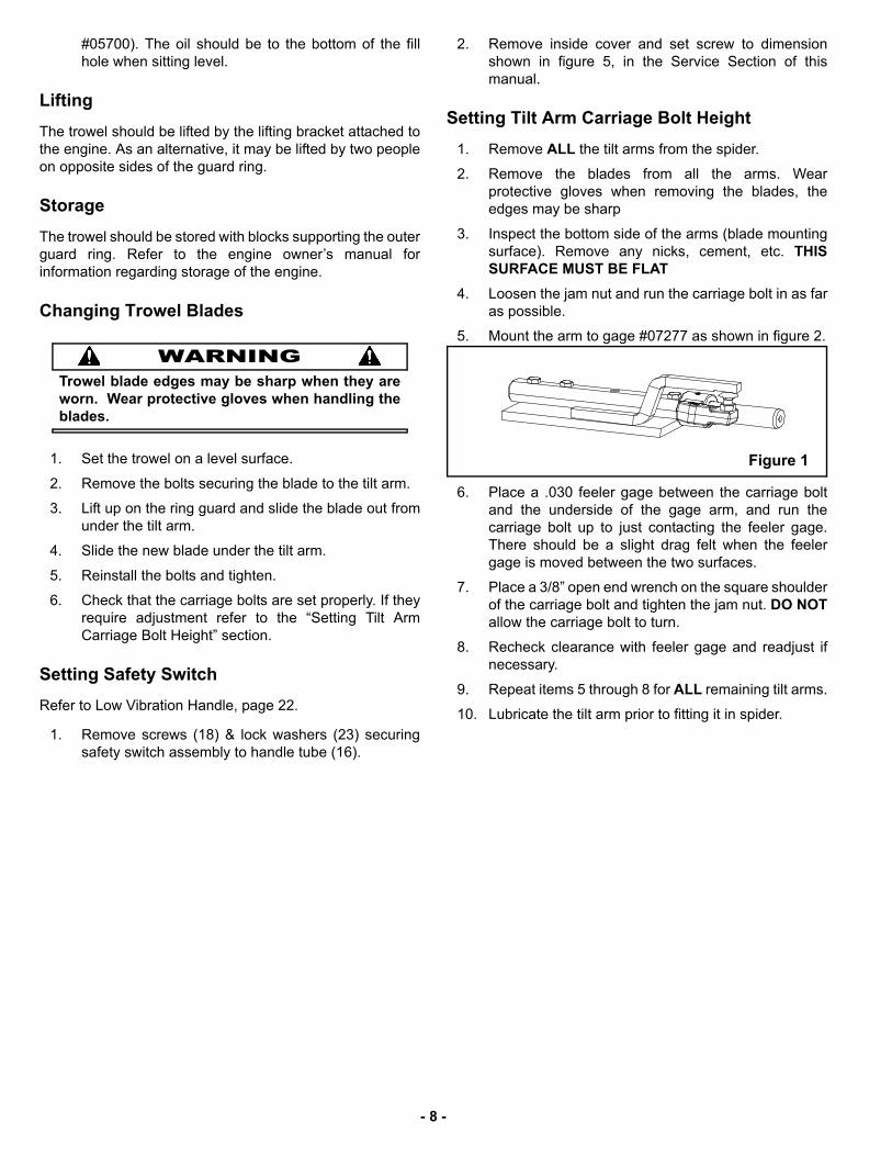
5. Mount the arm to gage #07277 as shown in figure 2.
6. Place a .030 feeler gage between the carriage boltand the underside of the gage arm, and run thecarriage bolt up to just contacting the feeler gage.There should be a slight drag felt when the feelergage is moved between the two surfaces.
7. Place a 3/8” open end wrench on the square shoulderof the carriage bolt and tighten the jam nut. DO NOTallow the carriage bolt to turn.
8. Recheck clearance with feeler gage and readjust ifnecessary.
9. Repeat items 5 through 8 for ALL remaining tilt arms.
10. Lubricate the tilt arm prior to fitting it in spider.
Figure 1
- 8 -
S E R V I C E
Assembly and disassembly should be performed by aservice technician who has been factory trained on MBWequipment. The unit should be clean and free of debris.Pressure washing before disassembly is recommended.
• Prior to assembly, wash all parts in a suitable cleaner orsolvent.
• Check moving parts for wear and failure. Refer to theReplacement section in this manual for tolerance andreplacement cycles.
• All shafts and housings should be oiled prior to pressingbearings. Also, ensure that the bearings are pressedsquare and are seated properly.
• All bearings, seals, o-rings and gaskets should bereplaced when rebuilding gearbox.
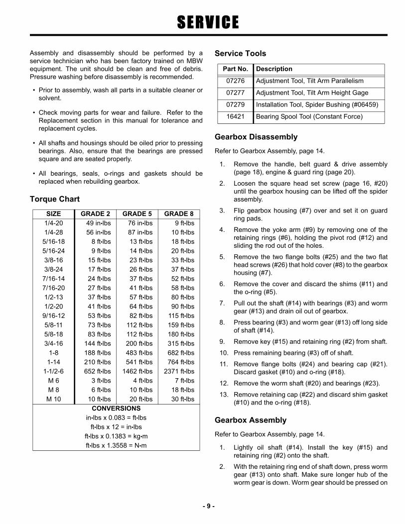
Torque Chart
Service Tools
Gearbox Disassembly
Refer to Gearbox Assembly, page 14.
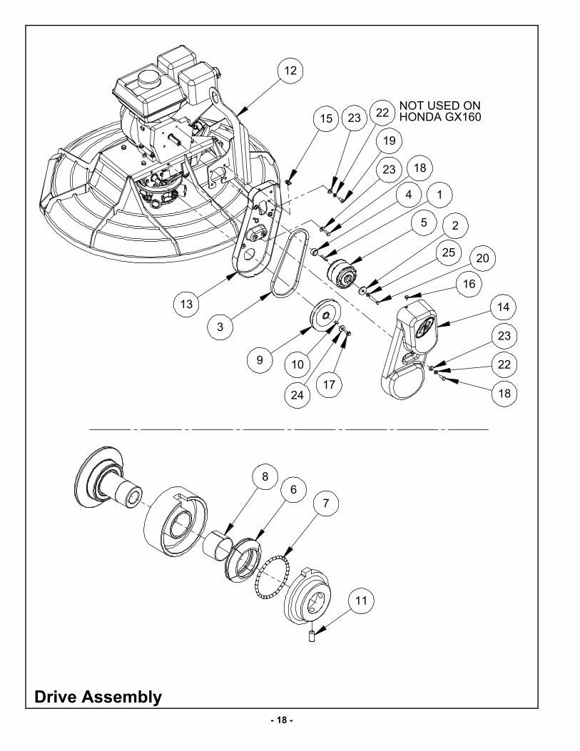
1. Remove the handle, belt guard & drive assembly(page 18), engine & guard ring (page 20).
2. Loosen the square head set screw (page 16, #20)until the gearbox housing can be lifted off the spiderassembly.
3. Flip gearbox housing (#7) over and set it on guardring pads.
4. Remove the yoke arm (#9) by removing one of theretaining rings (#6), holding the pivot rod (#12) andsliding the rod out of the holes.
5. Remove the two flange bolts (#25) and the two flathead screws (#26) that hold cover (#8) to the gearboxhousing (#7).
6. Remove the cover and discard the shims (#11) andthe o-ring (#5).
7. Pull out the shaft (#14) with bearings (#3) and wormgear (#13) and drain oil out of gearbox.
8. Press bearing (#3) and worm gear (#13) off long sideof shaft (#14).
9. Remove key (#15) and retaining ring (#2) from shaft.
10. Press remaining bearing (#3) off of shaft.
11. Remove flange bolts (#24) and bearing cap (#21).Discard gasket (#10) and o-ring (#18).
12. Remove the worm shaft (#20) and bearings (#23).
13. Remove retaining cap (#22) and discard shim gasket(#10) and the o-ring (#18).
Gearbox Assembly
Refer to Gearbox Assembly, page 14.
1. Lightly oil shaft (#14). Install the key (#15) andretaining ring (#2) onto the shaft.
2. With the retaining ring end of shaft down, press wormgear (#13) onto shaft. Make sure longer hub of theworm gear is down. Worm gear should be pressed on
SIZE GRADE 2 GRADE 5 GRADE 8
1/4-20 49 in•lbs 76 in•lbs 9 ft•lbs
1/4-28 56 in•lbs 87 in•lbs 10 ft•lbs
5/16-18 8 ft•lbs 13 ft•lbs 18 ft•lbs
5/16-24 9 ft•lbs 14 ft•lbs 20 ft•lbs
3/8-16 15 ft•lbs 23 ft•lbs 33 ft•lbs
3/8-24 17 ft•lbs 26 ft•lbs 37 ft•lbs
7/16-14 24 ft•lbs 37 ft•lbs 52 ft•lbs
7/16-20 27 ft•lbs 41 ft•lbs 58 ft•lbs
1/2-13 37 ft•lbs 57 ft•lbs 80 ft•lbs
1/2-20 41 ft•lbs 64 ft•lbs 90 ft•lbs
9/16-12 53 ft•lbs 82 ft•lbs 115 ft•lbs
5/8-11 73 ft•lbs 112 ft•lbs 159 ft•lbs
5/8-18 83 ft•lbs 112 ft•lbs 180 ft•lbs
3/4-16 144 ft•lbs 200 ft•lbs 315 ft•lbs
1-8 188 ft•lbs 483 ft•lbs 682 ft•lbs
1-14 210 ft•lbs 541 ft•lbs 764 ft•lbs
1-1/2-6 652 ft•lbs 1462 ft•lbs 2371 ft•lbs
M 6 3 ft•lbs 4 ft•lbs 7 ft•lbs
M 8 6 ft•lbs 10 ft•lbs 18 ft•lbs
M 10 10 ft•lbs 20 ft•lbs 30 ft•lbs
CONVERSIONS
in•lbs x 0.083 = ft•lbs
ft•lbs x 12 = in•lbs
ft•lbs x 0.1383 = kg•m
ft•lbs x 1.3558 = N•m
Part No. Description
07276 Adjustment Tool, Tilt Arm Parallelism
07277 Adjustment Tool, Tilt Arm Height Gage
07279 Installation Tool, Spider Bushing (#06459)
16421 Bearing Spool Tool (Constant Force)
- 9 -
the shaft until the recess in worm gear hub is snugagainst retaining ring.
3. Press one bearing (#3) on each end of the shaft.Make sure bearings are butted against worm gearshoulders.
4. If bearing races are replaced make sure new racesare properly seated.
5. Set worm gear and shaft assembly into gearboxhousing and put cover (#8) and one .010” shim#05401 (#11) into place.
6. Apply down pressure to cover (#8) and check shaft(#14) for end play.
7. Remove the cover and install the proper shims (#11)for no end play.
8. Brush a light coat of oil on o-ring groove and inside lipof cover. Roll o-ring (#5) over inside lip and intogroove in cover. Install seal (#1) into cover fromoutside and make sure it is installed square and flat.Then secure with retaining ring (#17).
9. Use a piece of thin plastic over shaft to protect sealand install cover into gearbox housing. Secure withtwo flange bolts (#25) and two flat head screws (#26).
10. Rotate shaft, there should be a little drag. If there istoo much drag another shim should be added until aslight seal drag is felt. If there is side play in the shafta shim must be removed.
11. Measure the main shaft run out, Maximumacceptable total indicator run out is .0035 inches.
12. Install drain plug (#27) and relief valve (#16) ifremoved. Use pipe sealant on the threads.
13. Brush a light coat of oil on o-ring (#18). Roll it overinside lip and into the groove of retaining cap (#22).
14. Install two .010” shims #05360 (#10) with retainingcap on drain plug side of gearbox housing with fourflange bolts (#24). Torque bolts to 90 in/lbs in an “X”pattern.
15. Press one bearing (#23) on each end of the wormshaft (#20). Make sure bearings are butted againstworm shaft steps.
16. Install worm shaft (#20) with bearings (#23) intogearbox housing. Gears must be meshed properly.
17. Install bearing cap (#21) and apply pressure towardsgearbox (#7). Rotate worm shaft and check for endplay and gear backlash.
18. Remove bearing cap and install proper shims (#10)for no back lash & no end play.
19. Install a new seal (#19) into bearing cap (#21) fromoutside. Make sure seal is installed square and flat.
20. Brush a light coat of oil on o-ring groove. Roll o-ring(#18) over inside lip and into groove of bearing cap.
21. Pour one can (21 oz.) of #05700 oil into worm shaftbearing cap opening. Install cap and secure with fourflange bolts (#24). Torque bolts to 90 in/lbs in an “X”pattern.
CFP Handle Cable/Spring Replacement
Refer to Constant Force Handle Assembly, page 24.
1. Remove handle assembly from machine.
2. Secure handle in a vise to for disassembly.
3. Loosen handle pivot bolt (#39) and fold handleforward.
4. Remove four bolts (#30) on the back of spring box.
5. Carefully rotate lever (#16) arm backwards until youfeel the cable tension release. When it releases therewill be no spring tension on lever (#16).
6. Remove retainer bolt (#43) and end covers (#23).
7. Remove remaining two bolts (#31) to separate springbox (#22) from handle.
8. With a long needle nose pliers, disconnect the cablefrom the spring.
9. If you are only replacing spring (#25) proceed withstep 10. If you are replacing cable and/or clevis referto step 13.
10. Note orientation of spring assembly. Remove bearingspool (# 26) by pushing it out either side.
11. Remove spring assembly by forcing it out either side.
12. Refer to step 18 for assembly.
13. Push threaded portion of cable into tube.
14. Slide clevis assembly out of tube toward the bottom.
15. Remove cable from tube.
16. Route barrel end of new cable into tube.
17. Route threaded portion of cable over pulley on clevisand back into tube. Guide threaded end through slotin handle as you insert clevis into handle tube. Insertone of the handle bolts through clevis mounting holesto hold it in place. See figure 4.
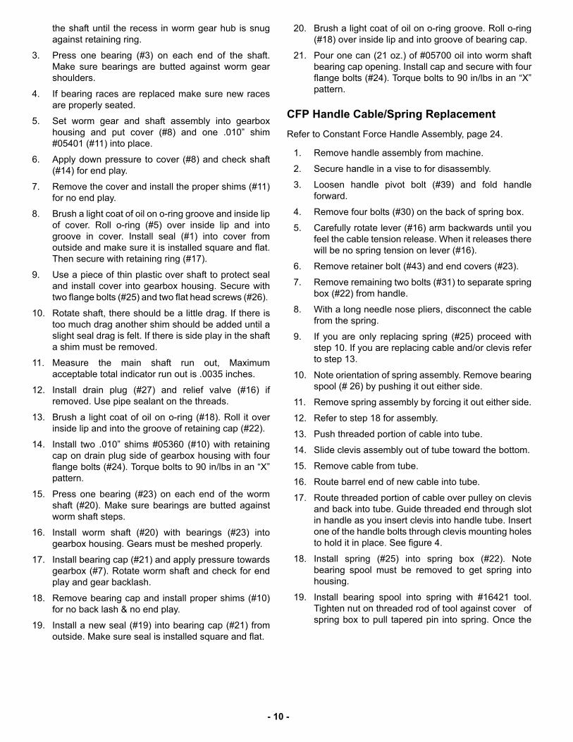
18. Install spring (#25) into spring box (#22). Notebearing spool must be removed to get spring intohousing.
19. Install bearing spool into spring with #16421 tool.Tighten nut on threaded rod of tool against cover ofspring box to pull tapered pin into spring. Once the
- 10 -
spring is spread, the spool can be inserted behindtapered pin and tool can be removed. See figure 2.
20. Hook cable end to spring (#25) and route cablearound activating cam (#15).
21. Install spring box side covers (#23) and secure withhardware.
22. Mount spring box onto handle using center mountpoint only. Align rear mounting holes but do not installbolts. Tighten center mount bolts.
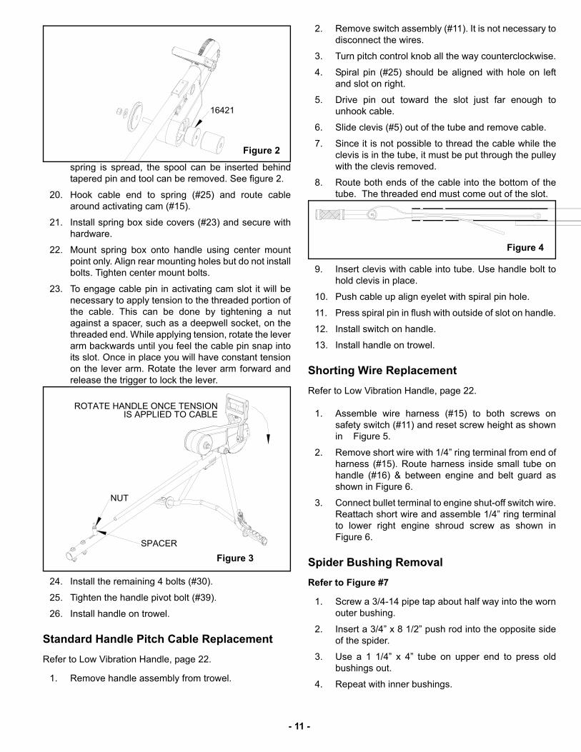
23. To engage cable pin in activating cam slot it will benecessary to apply tension to the threaded portion ofthe cable. This can be done by tightening a nutagainst a spacer, such as a deepwell socket, on thethreaded end. While applying tension, rotate the leverarm backwards until you feel the cable pin snap intoits slot. Once in place you will have constant tensionon the lever arm. Rotate the lever arm forward andrelease the trigger to lock the lever.
24. Install the remaining 4 bolts (#30).
25. Tighten the handle pivot bolt (#39).
26. Install handle on trowel.
Standard Handle Pitch Cable Replacement
Refer to Low Vibration Handle, page 22.
1. Remove handle assembly from trowel.
2. Remove switch assembly (#11). It is not necessary todisconnect the wires.
3. Turn pitch control knob all the way counterclockwise.
4. Spiral pin (#25) should be aligned with hole on leftand slot on right.
5. Drive pin out toward the slot just far enough tounhook cable.
6. Slide clevis (#5) out of the tube and remove cable.
7. Since it is not possible to thread the cable while theclevis is in the tube, it must be put through the pulleywith the clevis removed.
8. Route both ends of the cable into the bottom of thetube. The threaded end must come out of the slot.
9. Insert clevis with cable into tube. Use handle bolt tohold clevis in place.
10. Push cable up align eyelet with spiral pin hole.
11. Press spiral pin in flush with outside of slot on handle.
12. Install switch on handle.
13. Install handle on trowel.
Shorting Wire Replacement
Refer to Low Vibration Handle, page 22.
1. Assemble wire harness (#15) to both screws onsafety switch (#11) and reset screw height as shownin Figure 5.
2. Remove short wire with 1/4” ring terminal from end ofharness (#15). Route harness inside small tube onhandle (#16) & between engine and belt guard asshown in Figure 6.
3. Connect bullet terminal to engine shut-off switch wire.Reattach short wire and assemble 1/4” ring terminalto lower right engine shroud screw as shown inFigure 6.
Spider Bushing Removal
Refer to Figure #7
1. Screw a 3/4-14 pipe tap about half way into the wornouter bushing.
2. Insert a 3/4” x 8 1/2” push rod into the opposite sideof the spider.
3. Use a 1 1/4” x 4” tube on upper end to press oldbushings out.
4. Repeat with inner bushings.
16421
Figure 2
SPACER
NUT
ROTATE HANDLE ONCE TENSION IS APPLIED TO CABLE
Figure 3
Figure 4
- 11 -

Spider Bushing Replacement
Refer to Figure #8 for bushing installation:
1. Install (4) inner bushings into spider, using long sideof installation tool #60703 to ensure proper bushingdepth.
2. Using the opposite end or short end of installation tool#06703, install (4) outer bushings into spider.
Parts Replacement Cycles and Tolerances
3/4 - 14 PIPE TAP
TUBE 1 1/4 I.D. X 4" LONG
6459 BUSHING
PUSH ROD 3/4" X 8 1/2"
Figure 7
Inner Bushing Outer Bushing
Figure 8
Figure 5
Figure 6
Air Cleaner ElementReplace after 100 hours if the engine is operating under good clean air conditions.Service and replace more frequently if under more severe conditions.
BearingsReplace anytime a bearing is rough, binding, discolored or removed from housing orshaft.
Blades Replace when the edges become sharp or uneven. (Finish blades can be reversed)
Bushings, Trowel ArmReplace if the trowel arm can be moved up and down more than 3/4 inch (19 mm) atthe end of the arm.
Carriage BoltsReset the height after trowel arm teardown or if the trowel develops chatter orwindmilling. Use height gage kit #07277 when setting.
Clutch Replace clutch if it does not disengage below 2000 rpm.
Gaskets and Seals Replace at every overhaul and teardown. Use MBW gasket and seal kit #05470.
Gearbox OilReplace after the first 50 hours of operation, then every 500 operating hours or yearlythereafter.
Spark Plug Change after 75 hours of operation.
Torque BoltsRe-torque all the bolts after the first eight hours of operation and check every 25hours thereafter.
Worm Gear Replace if the teeth show wear marks or become sharp.
Worm Shaft Replace if the teeth show wear marks or become sharp.
- 12 -
- 13 -
MBW, Inc.250 Hartford Rd • PO Box 440Slinger, WI 53086-0440Phone: (262) 644-5234Fax: (262) 644-5169Email: [email protected]: www.mbw.com
MBW (UK) Ltd.Units 2 & 3Cochrane StreetBolton BL3 6BN, EnglandPhone: 01204 387784Fax: 01204 387797
Contact Information
MBW France S.A.R.LPhone: +33 (0) 3 44 07 15 96Fax: +33 (0) 3 44 07 41 28
R E P L A C E M E N T PA R T S
The warranty is stated in this book on page 26. Failure toreturn the Warranty Registration Card renders the warrantynull and void.
MBW, Inc. has established a network of reputabledistributors with trained mechanics and full facilities formaintenance and rebuilding, and to carry an adequate partsstock in all areas of the country. Their sales engineers areavailable for professional consultation. If you cannot locatean M-B-W distributor in your area, contact MBW, Inc. or oneof our Sales Branches listed below.
When ordering replacement parts, be sure to have thefollowing information available:
• Model and Serial Number of machine when orderingM-B-W parts
• Model and Serial Number of engine when orderingengine parts
• Part Number, Description, and Quantity
• Company Name, Address, Zip Code, and PurchaseOrder Number
• Preferred method of shipping
REMEMBER - You own the best! If repairs are needed,use only M-B-W parts purchased from authorizedM-B-W distributors.
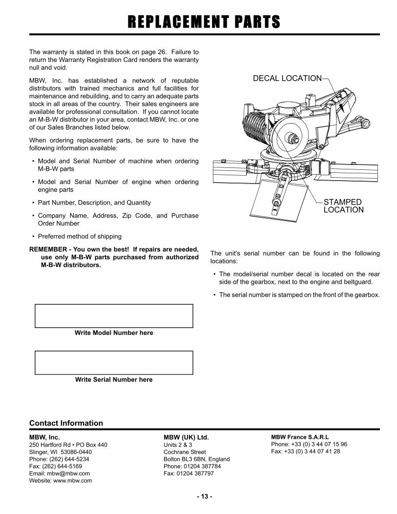
The unit’s serial number can be found in the followinglocations:
• The model/serial number decal is located on the rearside of the gearbox, next to the engine and beltguard.
• The serial number is stamped on the front of the gearbox.
Write Model Number here
Write Serial Number here
DECAL LOCATION
STAMPEDLOCATION

- 14 -
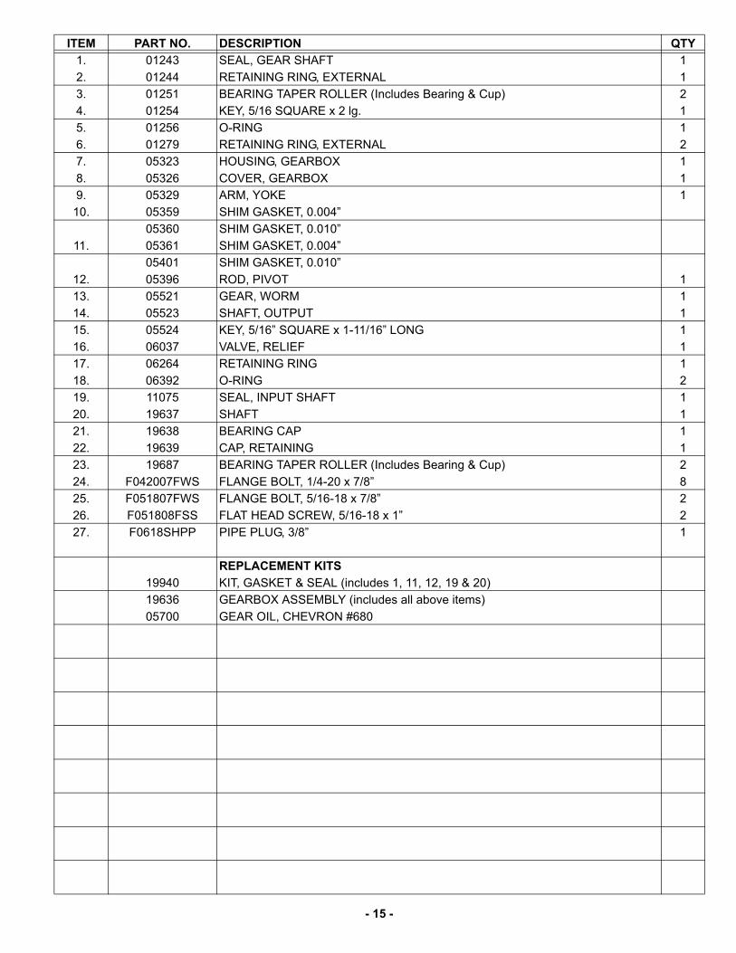
Gearbox Assembly
- 15 -
ITEM PART NO. DESCRIPTION QTY
1. 01243 SEAL, GEAR SHAFT 1
2. 01244 RETAINING RING, EXTERNAL 1
3. 01251 BEARING TAPER ROLLER (Includes Bearing & Cup) 2
4. 01254 KEY, 5/16 SQUARE x 2 lg. 1
5. 01256 O-RING 1
6. 01279 RETAINING RING, EXTERNAL 2
7. 05323 HOUSING, GEARBOX 1
8. 05326 COVER, GEARBOX 1
9. 05329 ARM, YOKE 1
10. 05359 SHIM GASKET, 0.004”
05360 SHIM GASKET, 0.010”
11. 05361 SHIM GASKET, 0.004”
05401 SHIM GASKET, 0.010”
12. 05396 ROD, PIVOT 1
13. 05521 GEAR, WORM 1
14. 05523 SHAFT, OUTPUT 1
15. 05524 KEY, 5/16” SQUARE x 1-11/16” LONG 1
16. 06037 VALVE, RELIEF 1
17. 06264 RETAINING RING 1
18. 06392 O-RING 2
19. 11075 SEAL, INPUT SHAFT 1
20. 19637 SHAFT 1
21. 19638 BEARING CAP 1
22. 19639 CAP, RETAINING 1
23. 19687 BEARING TAPER ROLLER (Includes Bearing & Cup) 2
24. F042007FWS FLANGE BOLT, 1/4-20 x 7/8” 8
25. F051807FWS FLANGE BOLT, 5/16-18 x 7/8” 2
26. F051808FSS FLAT HEAD SCREW, 5/16-18 x 1” 2
27. F0618SHPP PIPE PLUG, 3/8” 1
REPLACEMENT KITS
19940 KIT, GASKET & SEAL (includes 1, 11, 12, 19 & 20)
19636 GEARBOX ASSEMBLY (includes all above items)
05700 GEAR OIL, CHEVRON #680

- 16 -
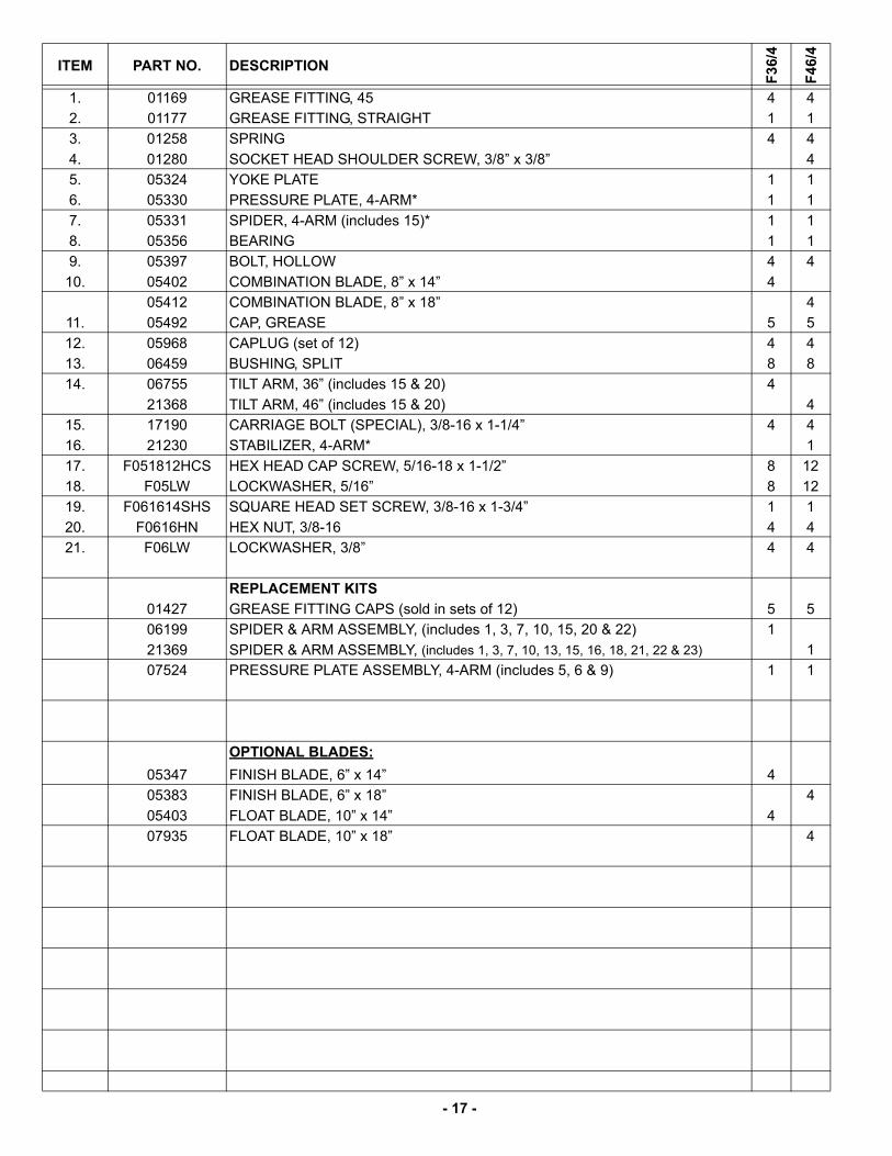
Spider Assembly
- 17 -
ITEM PART NO. DESCRIPTION
F3
6/4
F4
6/4
1. 01169 GREASE FITTING, 45 4 4
2. 01177 GREASE FITTING, STRAIGHT 1 1
3. 01258 SPRING 4 4
4. 01280 SOCKET HEAD SHOULDER SCREW, 3/8” x 3/8” 4
5. 05324 YOKE PLATE 1 1
6. 05330 PRESSURE PLATE, 4-ARM* 1 1
7. 05331 SPIDER, 4-ARM (includes 15)* 1 1
8. 05356 BEARING 1 1
9. 05397 BOLT, HOLLOW 4 4
10. 05402 COMBINATION BLADE, 8” x 14” 4
05412 COMBINATION BLADE, 8” x 18” 4
11. 05492 CAP, GREASE 5 5
12. 05968 CAPLUG (set of 12) 4 4
13. 06459 BUSHING, SPLIT 8 8
14. 06755 TILT ARM, 36” (includes 15 & 20) 4
21368 TILT ARM, 46” (includes 15 & 20) 4
15. 17190 CARRIAGE BOLT (SPECIAL), 3/8-16 x 1-1/4” 4 4
16. 21230 STABILIZER, 4-ARM* 1
17. F051812HCS HEX HEAD CAP SCREW, 5/16-18 x 1-1/2” 8 12
18. F05LW LOCKWASHER, 5/16” 8 12
19. F061614SHS SQUARE HEAD SET SCREW, 3/8-16 x 1-3/4” 1 1
20. F0616HN HEX NUT, 3/8-16 4 4
21. F06LW LOCKWASHER, 3/8” 4 4
REPLACEMENT KITS
01427 GREASE FITTING CAPS (sold in sets of 12) 5 5
06199 SPIDER & ARM ASSEMBLY, (includes 1, 3, 7, 10, 15, 20 & 22) 1
21369 SPIDER & ARM ASSEMBLY, (includes 1, 3, 7, 10, 13, 15, 16, 18, 21, 22 & 23) 1
07524 PRESSURE PLATE ASSEMBLY, 4-ARM (includes 5, 6 & 9) 1 1
OPTIONAL BLADES:
05347 FINISH BLADE, 6” x 14” 4
05383 FINISH BLADE, 6” x 18” 4
05403 FLOAT BLADE, 10” x 14” 4
07935 FLOAT BLADE, 10” x 18” 4
- 18 -
Drive Assembly

- 19 -
ITEM PART NO. DESCRIPTION
GX
16
0
GX
27
0
GX
39
0
1. 00032 KEY, 3/16” SQUARE x 1-5/8” LONG 1
01161 KEY, 1/4” SQUARE x 1-1/2” LONG 1 1
2. 01099 WASHER, 5/16” SPECIAL 1
06638 WASHER, 3/8” SPECIAL 1 1
3. 01289 V-BELT, A-27 1
01078 V-BELT, A-29 1 1
07288 V-BELT, A-32 (F46/4HD only) 1
4. 06378 SPACER 1 1
5. 06473 CLUTCH 3/4” BORE (includes 6,7,8 & 11) 1
06606 CLUTCH 1” BORE (includes 6, 7, 8 & 11) 1 1
6. 06618 WEIGHT (set of 4) 1 1 1
7. 06619 SPRING 1 1 1
8. 06620 BEARING 1 1 1
9. 06746 SHEAVE 1 1 1
10. 06858 KEY, 3/16” SQUARE x 5/8” LONG 1 1 1
11. 19401 SCOCKET HEAD CUP POINT SET SCREW, 5/16-18x5/8 1 1 1
12. 19370 LIFTHOOK, TROWEL (For engines 5-7 hp.) 1
19372 LIFTHOOK, TROWEL (For engines 9-13 hp.) 1 1
13. 19666 BELT GUARD, BACK PLATE ASSEMBLY (Includes item #15) 1 1 1
14. 19668 BELT GUARD, FRONT COVER 1 1 1
15. 19804 CLIP NUT, 1/4-20 1 1 1
16. F042004FWS FLANGE SCREW, 1/4-20 x 1/2” 1 1 1
17. F051806FWS FLANGE SCREW, 5/16-18 x 3/4” 1 1 1
18. F051808HCS HEX HEAD CAP SCREW, 5/16-18 x 1” 4 4 4
19. F052406BCS BUTTON CAP SCREW, TORX, 5/16-24 x 3/4" 4
F052408HCS HEX HEAD CAP SCREW, 5/16-24 x 1” 4 4
20. F052416HCS HEX HEAD CAP SCREW, 5/16-24 x 2” 1
F072012HCS HEX HEAD CAP SCREW, 7/16-20 x1-1/2 1
F062410SCS SCOCKET HEAD CAP SCREW, 3/8-24 x 1-1/4 1
21. F0518ELN NYLON LOCKNUT, 5/16-18 2 2 2
22. F05LW LOCKWASHER, 5/16” 2 6 6
23. F05SW WASHER, 5/16 8 8 8
24. F06SW WASHER, 3/8” 1 1 1
25. F05LW LOCKWASHER, 5/16” 1
F07LW LOCKWASHER, 7/16” 1
F06LW LOCKWASHER, 3/8” 1
KITS:
20250 HEAVY WEIGHT TROWEL 1

- 20 -
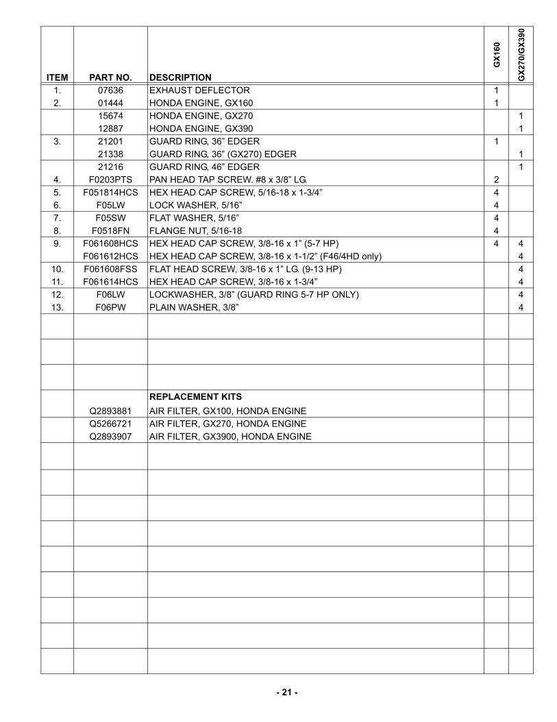
Guard Assembly
- 21 -
ITEM PART NO. DESCRIPTION
GX
160
GX
270/
GX
390
1. 07636 EXHAUST DEFLECTOR 1
2. 01444 HONDA ENGINE, GX160 1
15674 HONDA ENGINE, GX270 1
12887 HONDA ENGINE, GX390 1
3. 21201 GUARD RING, 36” EDGER 1
21338 GUARD RING, 36” (GX270) EDGER 1
21216 GUARD RING, 46” EDGER 1
4. F0203PTS PAN HEAD TAP SCREW. #8 x 3/8” LG. 2
5. F051814HCS HEX HEAD CAP SCREW, 5/16-18 x 1-3/4” 4
6. F05LW LOCK WASHER, 5/16” 4
7. F05SW FLAT WASHER, 5/16” 4
8. F0518FN FLANGE NUT, 5/16-18 4
9. F061608HCS HEX HEAD CAP SCREW, 3/8-16 x 1” (5-7 HP) 4 4
F061612HCS HEX HEAD CAP SCREW, 3/8-16 x 1-1/2” (F46/4HD only) 4
10. F061608FSS FLAT HEAD SCREW, 3/8-16 x 1” LG. (9-13 HP) 4
11. F061614HCS HEX HEAD CAP SCREW, 3/8-16 x 1-3/4” 4
12. F06LW LOCKWASHER, 3/8” (GUARD RING 5-7 HP ONLY) 4
13. F06PW PLAIN WASHER, 3/8” 4
REPLACEMENT KITS
Q2893881 AIR FILTER, GX100, HONDA ENGINE
Q5266721 AIR FILTER, GX270, HONDA ENGINE
Q2893907 AIR FILTER, GX3900, HONDA ENGINE
- 22 -
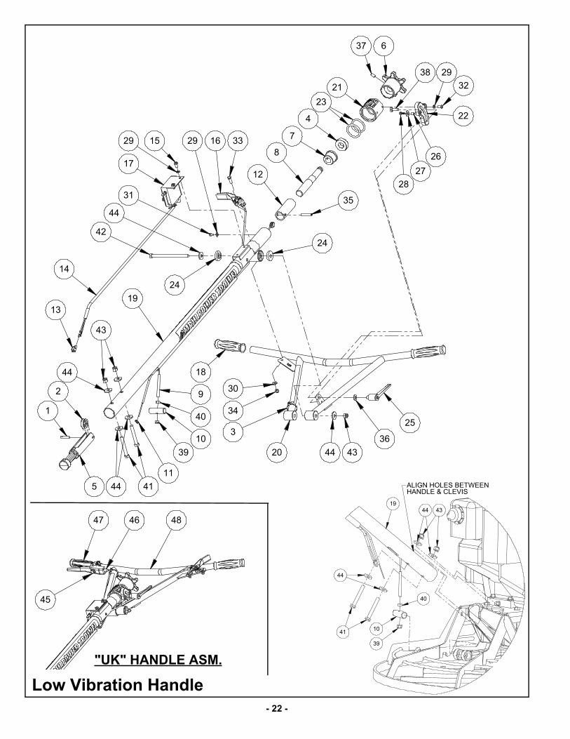
Low Vibration Handle
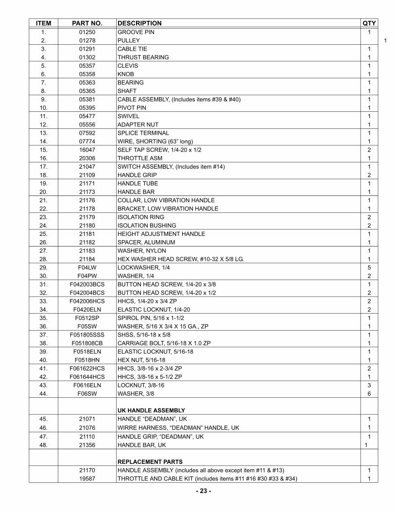
- 23 -
ITEM PART NO. DESCRIPTION QTY1. 01250 GROOVE PIN 1
2. 01278 PULLEY 1
3. 01291 CABLE TIE 1
4. 01302 THRUST BEARING 1
5. 05357 CLEVIS 1
6. 05358 KNOB 1
7. 05363 BEARING 1
8. 05365 SHAFT 1
9. 05381 CABLE ASSEMBLY, (Includes items #39 & #40) 1
10. 05395 PIVOT PIN 1
11. 05477 SWIVEL 1
12. 05556 ADAPTER NUT 1
13. 07592 SPLICE TERMINAL 1
14. 07774 WIRE, SHORTING (63” long) 1
15. 16047 SELF TAP SCREW, 1/4-20 x 1/2 2
16. 20306 THROTTLE ASM 1
17. 21047 SWITCH ASSEMBLY, (Includes item #14) 1
18. 21109 HANDLE GRIP 2
19. 21171 HANDLE TUBE 1
20. 21173 HANDLE BAR 1
21. 21176 COLLAR, LOW VIBRATION HANDLE 1
22. 21178 BRACKET, LOW VIBRATION HANDLE 1
23. 21179 ISOLATION RING 2
24. 21180 ISOLATION BUSHING 2
25. 21181 HEIGHT ADJUSTMENT HANDLE 1
26. 21182 SPACER, ALUMINUM 1
27. 21183 WASHER, NYLON 1
28. 21184 HEX WASHER HEAD SCREW, #10-32 X 5/8 LG. 1
29. F04LW LOCKWASHER, 1/4 5
30. F04PW WASHER, 1/4 2
31. F042003BCS BUTTON HEAD SCREW, 1/4-20 x 3/8 1
32. F042004BCS BUTTON HEAD SCREW, 1/4-20 x 1/2 2
33. F042006HCS HHCS, 1/4-20 x 3/4 ZP 2
34. F0420ELN ELASTIC LOCKNUT, 1/4-20 2
35. F0512SP SPIROL PIN, 5/16 x 1-1/2 1
36. F05SW WASHER, 5/16 X 3/4 X 15 GA., ZP 1
37. F051805SSS SHSS, 5/16-18 x 5/8 1
38. F051808CB CARRIAGE BOLT, 5/16-18 X 1.0 ZP 1
39. F0518ELN ELASTIC LOCKNUT, 5/16-18 1
40. F0518HN HEX NUT, 5/16-18 1
41. F061622HCS HHCS, 3/8-16 x 2-3/4 ZP 2
42. F061644HCS HHCS, 3/8-16 x 5-1/2 ZP 1
43. F0616ELN LOCKNUT, 3/8-16 3
44. F06SW WASHER, 3/8 6
UK HANDLE ASSEMBLY
45. 21071 HANDLE “DEADMAN”, UK 1
46. 21076 WIRRE HARNESS, “DEADMAN” HANDLE, UK 1
47. 21110 HANDLE GRIP, “DEADMAN”, UK 1
48. 21356 HANDLE BAR, UK 1
REPLACEMENT PARTS
21170 HANDLE ASSEMBLY (includes all above except item #11 & #13) 1
19587 THROTTLE AND CABLE KIT (includes items #11 #16 #30 #33 & #34) 1
- 24 -
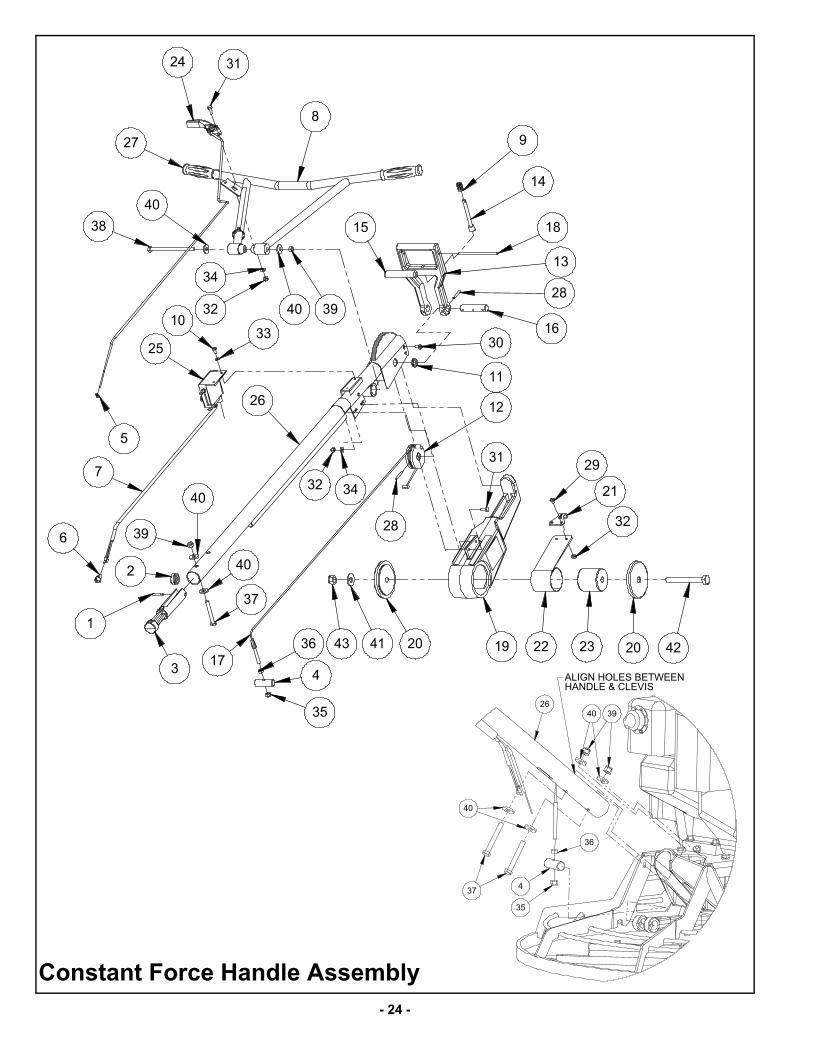
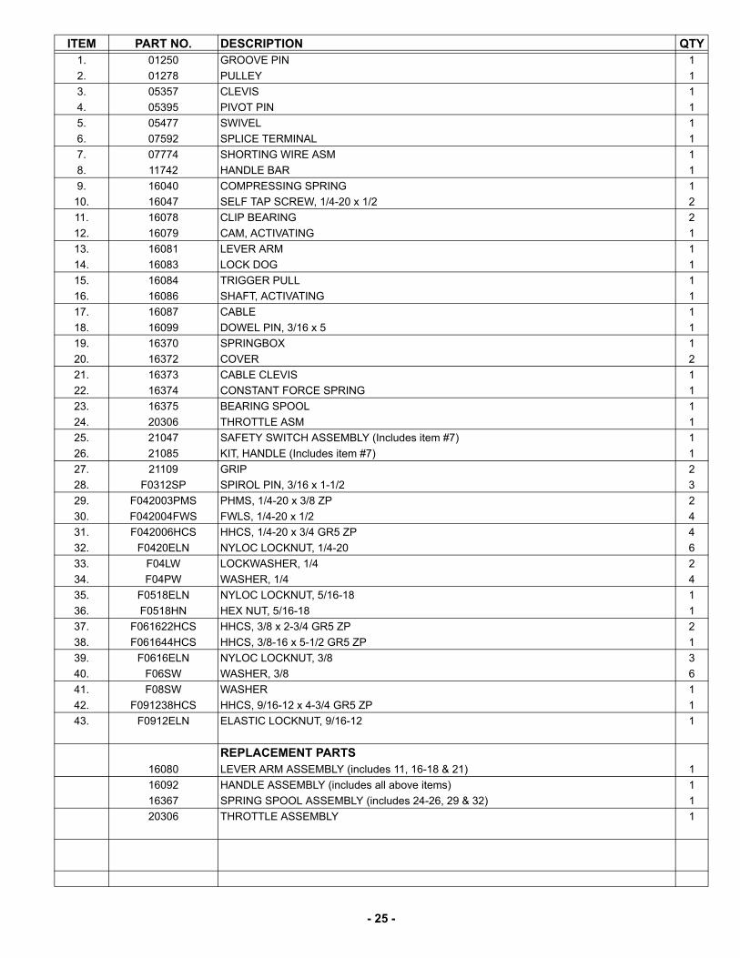
Constant Force Handle Assembly
- 25 -
ITEM PART NO. DESCRIPTION QTY1. 01250 GROOVE PIN 1
2. 01278 PULLEY 1
3. 05357 CLEVIS 1
4. 05395 PIVOT PIN 1
5. 05477 SWIVEL 1
6. 07592 SPLICE TERMINAL 1
7. 07774 SHORTING WIRE ASM 1
8. 11742 HANDLE BAR 1
9. 16040 COMPRESSING SPRING 1
10. 16047 SELF TAP SCREW, 1/4-20 x 1/2 2
11. 16078 CLIP BEARING 2
12. 16079 CAM, ACTIVATING 1
13. 16081 LEVER ARM 1
14. 16083 LOCK DOG 1
15. 16084 TRIGGER PULL 1
16. 16086 SHAFT, ACTIVATING 1
17. 16087 CABLE 1
18. 16099 DOWEL PIN, 3/16 x 5 1
19. 16370 SPRINGBOX 1
20. 16372 COVER 2
21. 16373 CABLE CLEVIS 1
22. 16374 CONSTANT FORCE SPRING 1
23. 16375 BEARING SPOOL 1
24. 20306 THROTTLE ASM 1
25. 21047 SAFETY SWITCH ASSEMBLY (Includes item #7) 1
26. 21085 KIT, HANDLE (Includes item #7) 1
27. 21109 GRIP 2
28. F0312SP SPIROL PIN, 3/16 x 1-1/2 3
29. F042003PMS PHMS, 1/4-20 x 3/8 ZP 2
30. F042004FWS FWLS, 1/4-20 x 1/2 4
31. F042006HCS HHCS, 1/4-20 x 3/4 GR5 ZP 4
32. F0420ELN NYLOC LOCKNUT, 1/4-20 6
33. F04LW LOCKWASHER, 1/4 2
34. F04PW WASHER, 1/4 4
35. F0518ELN NYLOC LOCKNUT, 5/16-18 1
36. F0518HN HEX NUT, 5/16-18 1
37. F061622HCS HHCS, 3/8 x 2-3/4 GR5 ZP 2
38. F061644HCS HHCS, 3/8-16 x 5-1/2 GR5 ZP 1
39. F0616ELN NYLOC LOCKNUT, 3/8 3
40. F06SW WASHER, 3/8 6
41. F08SW WASHER 1
42. F091238HCS HHCS, 9/16-12 x 4-3/4 GR5 ZP 1
43. F0912ELN ELASTIC LOCKNUT, 9/16-12 1
REPLACEMENT PARTS16080 LEVER ARM ASSEMBLY (includes 11, 16-18 & 21) 1
16092 HANDLE ASSEMBLY (includes all above items) 1
16367 SPRING SPOOL ASSEMBLY (includes 24-26, 29 & 32) 1
20306 THROTTLE ASSEMBLY 1
- 26 -
W A R R A N T Y
WHAT DOES THIS WARRANTY COVER? MBW, Incorporated (MBW) warrants each New Machine against defects in material and workmanship for a period of twelve (12) months. "New Machine" means a machine shipped directly from MBW or authorized MBW dealer to the end user. This warranty commences on the first day the machine is sold, assigned to a rental fleet, or otherwise put to first use.
MBW warrants each Demonstration Machine against defects in material and workmanship for a period of six (6) months. "Demonstration Machine" means a machine used by MBW or its agents for promotional purposes. This warranty commences on the first day the machine is sold, assigned to a rental fleet, or otherwise put to first use.
This warranty covers the labor cost for replacement or repair of parts, components, or equipment on New Machines or Demonstration Machines, and MBW shall pay labor costs at MBW's prevailing rate to affect the warranted repair or replacement. MBW reserves the right to adjust labor claims on a claim-by-claim basis.
This warranty covers the shipping cost of replacement parts, components, or equipment via common ground carriers from MBW to an authorized MBW dealer. Air freight is considered only in cases where ground transportation is not practical.
MAY THIS WARRANTY BE TRANSFERRED? This warranty is non-transferable and only applies to the original end user of a new machine or demonstration machine.
WHAT DOES THIS WARRANTY NOT COVER?1.This warranty does not cover any Used Equipment. "Used Equipment" means any MBW machine or equipment that is not a New Machine or a Demonstration Machine. All Used Equipment is sold AS IS/WHERE IS WITH ALL FAULTS.
2.This warranty does not cover any New Machine, Demonstration Machine, or their equipment, parts, or components altered or modified in any way without MBW's prior written consent. This warranty does not cover the use of parts not specifically approved by MBW for use on MBW products. This warranty does not cover misuse, neglect, shipping damage, accidents, acts of God, the operation of any New Machine or Demonstration Machine in any way other than recommended by MBW in accordance with its specifications, or any other circumstances beyond MBW's control. This warranty does not cover any New Machine or Demonstration Machine repaired by anyone other than MBW factory branches or authorized MBW distributors.
3.This warranty does not cover, and MBW affirmatively disclaims, liability for any damage or injury resulting directly or indirectly from design, materials, or operation of a New Machine or Demonstration Machine or any other MBW product. MBW's liability with respect to any breach of warranty shall be limited to the provisions of this document and in no event shall exceed an amount equal to the purchase price of the New Machine or Demonstration Machine purchased from MBW.
4.This warranty does not cover engines, motors, and other assemblies or components produced by other manufacturers and used on a New Machine or Demonstration Machine, as said engines, motors, and other assemblies or components may have warranties provided by the manufacturer thereof. This warranty does not apply to consumable items, such as v-belts, filters, trowel and screed blades, seals, shock mounts, batteries, and the like, all of which are sold AS IS/WHERE IS WITH ALL FAULTS.
5.This warranty does not cover the cost of transportation and other expenses which may be connected with warranty service but not specifically mentioned herein.
6.This warranty does not cover any updates to any New Machine, Demonstration Machine, or any other MBW product. MBW reserves the right to improve or make product changes without incurring any obligation to update, refit, or install the same on New Machines or Demonstration Machines previously sold.
WHAT MUST YOU DO TO OBTAIN WARRANTY COVERAGE? Each New Machine or Demonstration Machine is accompanied by a Warranty Registration Card. You must sign, date, and return the Warranty Registration Card to the place of origin of the New Machine or Demonstration Machine, either to MBW, Inc. at P.O. Box 440, Slinger, Wisconsin 53086, MBW (UK), Ltd. at Units 2 & 3 Cochrane Street, Bolton BL3 6BN, United Kingdom or MBW FRANCE SARL at ZA D'Outreville, 5 Rue Jean Baptiste Neron, Bornel 60540 France, within ten (10) days after purchase, assignment to a rental fleet, or first use. This signed warranty card is the buyer's affirmation that he has read, understood, and accepted the warranty at the time of purchase. Failure to return the warranty card as specified herein renders the warranty null and void. In order to receive warranty coverage consideration, warranty claims must be submitted within thirty (30) days after the New Machine or Demonstration Machine fails. Warranty claims must be submitted to MBW, Inc., MBW (UK), Ltd. or MBW FRANCE SARL, and written authorization for the return of merchandise or parts under the warranty must be obtained before shipment to MBW.
WHAT WILL MBW DO? MBW's obligation under this warranty is limited to the replacement or repair of parts for a New Machine or Demonstration Machine at MBW factory branches or at authorized MBW distributors, and such replacement or repair is the exclusive remedy provided hereunder. Labor must be performed at an authorized MBW distributor. MBW reserves the right to inspect and render a final decision on each warranty case, and MBW's repair or replacement is solely within the discretion of MBW.
IT IS EXPRESSLY AGREED THAT THIS SHALL BE THE SOLE AND EXCLUSIVE REMEDY UNDER THIS WARRANTY. UNDER NO CIRCUMSTANCES SHALL MBW BE LIABLE FOR ANY COSTS, LOSS, EXPENSE, DAMAGES, SPECIAL DAMAGES, INCIDENTAL DAMAGES, OR PUNITIVE DAMAGES ARISING DIRECTLY OR INDIRECTLY FROM THE USE OF THE NEW MACHINE OR DEMONSTRATION MACHINE WHETHER BASED UPON WARRANTY, CONTRACT, NEGLIGENCE, STRICT LIABILITY, OR ANY OTHER LEGAL THEORY.
THE FOREGOING WARRANTY IS EXPRESSLY IN LIEU OF ALL OTHER WARRANTIES, EXPRESS OR IMPLIED, INCLUDING THE WARRANTIES OF MERCHANTABILITY, FITNESS FOR USE, AND FITNESS FOR A PARTICULAR PURPOSE, AND ALL OTHER OBLIGATIONS OR LIABILITY ON MBW'S PART. MBW NEITHER ASSUMES NOR AUTHORIZES ANY OTHER PERSON TO ASSUME ON BEHALF OF MBW ANY OTHER LIABILITY OR WARRANTY IN CONNECTION WITH THE SALE OR SERVICE OF ANY NEW MACHINE, DEMONSTRATION MACHINE , OR ANY OTHER MBW PRODUCT.
EXTENDED RAMMER WARRANTY - MODELS R422, R442, R482 & R483.This extended warranty commences on the last day of MBW’s standard, one year, “limited warranty” and runs for an additional four years(48 months). This extended warranty is limited to part replacement and shipping costs of rammer bellows and non-metallic slide bearings only. This extended warranty does not cover labor, down time, or any other cost beyond that of component replacement and freight. This extended warranty is subject to all limitations set fourth in MBW’s “limited warranty”, above.


![MAN-05-765 Manuel utilisateur[E] - Manac semi trailer ... · PDF fileOperator’s instructions This manual has been prepared to assist you in retaining the safety, dependability, and](https://img.pdfslide.us/doc/110x75/5a7a15c77f8b9ae5058ce0dd/man-05-765-manuel-utilisateure-manac-semi-trailer-s-instructions-this.jpg)