Embed Size (px)
Citation preview
5000184075 08 0612
5 0 0 0 1 8 4 0 7 5
Operator’s Manual
Vibratory Rammer
BS 50-2
EN
Copyright notice
© Copyright 2012 by Wacker Neuson Production Americas LLCAll rights, including copying and distribution rights, are reserved.This publication may be photocopied by the original purchaser of the machine. Any other type of reproduction is prohibited without express written permission from Wacker Neuson Production Americas LLC.Any type of reproduction or distribution not authorized by Wacker Neuson Production Americas LLC represents an infringement of valid copyrights. Violators will be prosecuted.
Trademarks All trademarks referenced in this manual are the property of their respective owners.
Manufacturer Wacker Neuson Production Americas LLCN92W15000 Anthony AvenueMenomonee Falls, WI 53051 U.S.A.Tel: (262) 255-0500 · Fax: (262) 255-0550 · Tel: (800) 770-0957www.wackerneuson.com
Original instructions
This Operator’s Manual presents the original instructions. The original language of this Operator’s Manual is American English.
BS 50-2 Foreword
ForewordSAVE THESE INSTRUCTIONS—This manual contains important instructions for the machine models below. These instructions have been written expressly by Wacker Neuson Production Americas LLC and must be followed during installation, operation, and maintenance of the machines.;
Machine documentation
From this point forward in this documentation, Wacker Neuson Production Americas LLC will be referred to as Wacker Neuson.Keep a copy of the Operator’s Manual with the machine at all times. Use the separate Parts Book supplied with the machine to order replacement parts. Refer to the separate Repair Manual for detailed instructions on servicing and repairing the machine.If you are missing any of these documents, please contact Wacker Neuson to order a replacement or visit www.wackerneuson.com. When ordering parts or requesting service information, be prepared to provide the machine model number, item number, revision number, and serial number.
Expectations for information in this manual
This manual provides information and procedures to safely operate and maintain the above Wacker Neuson model(s). For your own safety and to reduce the risk of injury, carefully read, understand, and observe all instructions described in this manual. Wacker Neuson expressly reserves the right to make technical modifications, even without notice, which improve the performance or safety standards of its machines.The information contained in this manual is based on machines manufactured up until the time of publication. Wacker Neuson reserves the right to change any portion of this information without notice.
CALIFORNIA Proposition 65 Warning
Engine exhaust, some of its constituents, and certain vehicle components, contain or emit chemicals known to the State of California to cause cancer and birth defects or other reproductive harm.
Machine Item Number Revision Machine Item Number RevisionBS 50-2 0009384 Rev 121,
Rev 200+BS 50-2 0620048 Rev 115,
Rev 200+BS 50-2 0009410 Rev 121,
Rev 200+BS 50-2 0620609 Rev 100+
BS 50-2 0009411 Rev 121, Rev 200+
BS 50-2 0620610 Rev 100+
BS 50-2 0009413 Rev 121, Rev 200+
BS 50-2 0620733 Rev 100+
BS 50-2 0620025 Rev 115, Rev 200+
— — —
wc_tx001354gb.fm 3
Foreword BS 50-2
Laws pertaining to spark arrestersNOTICE: State Health Safety Codes and Public Resources Codes specify that in certain locations spark arresters be used on internal combustion engines that use hydrocarbon fuels. A spark arrester is a device designed to prevent accidental discharge of sparks or flames from the engine exhaust. Spark arresters are qualified and rated by the United States Forest Service for this purpose. In order to comply with local laws regarding spark arresters, consult the engine distributor or the local Health and Safety Administrator.
Manufacturer’s approval
This manual contains references to approved parts, attachments, and modifications. The following definitions apply:
Approved parts or attachments are those either manufactured or provided by Wacker Neuson. Approved modifications are those performed by an authorized Wacker Neuson service center according to written instructions published by Wacker Neuson.Unapproved parts, attachments, and modifications are those that do not meet the approved criteria.
Unapproved parts, attachments, or modifications may have the following consequences:
Serious injury hazards to the operator and persons in the work areaPermanent damage to the machine which will not be covered under warranty
Contact your Wacker Neuson dealer immediately if you have questions about approved or unapproved parts, attachments, or modifications.
4 wc_tx001354gb.fm
Original Declaration of Conformity
2012
-CE-
BS50
-2-2
i_en
.fm
EC Declaration of Conformity
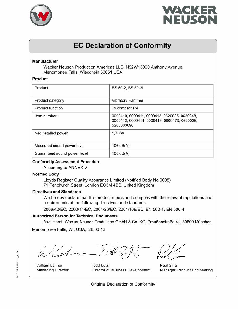
ManufacturerWacker Neuson Production Americas LLC, N92W15000 Anthony Avenue, Menomonee Falls, Wisconsin 53051 USA
Product
Product
Product category
Product function
Item number
Net installed power
Measured sound power level
Guaranteed sound power level
BS 50-2, BS 50-2i
Vibratory Rammer
To compact soil
0009410, 0009411, 0009413, 0620025, 0620048, 0009412, 0009414, 0009416, 0009473, 0620026,5200003696
1,7 kW
106 dB(A)
108 dB(A)
Conformity Assessment ProcedureAccording to ANNEX VIII
Notified BodyLloyds Register Quality Assurance Limited (Notified Body No 0088)71 Fenchurch Street, London EC3M 4BS, United Kingdom
Directives and StandardsWe hereby declare that this product meets and complies with the relevant regulations and requirements of the following directives and standards:2006/42/EC, 2000/14/EC, 2004/26/EC, 2004/108/EC, EN 500-1, EN 500-4
Authorized Person for Technical DocumentsAxel Häret, Wacker Neuson Produktion GmbH & Co. KG, Preußenstraße 41, 80809 München
Menomonee Falls, WI, USA, 28.06.12
William LahnerManaging Director
Paul SinaManager, Product Engineering
Todd LutzDirector of Business Development

Table of ContentsBS 50-2
Foreword 3
EC Declaration of Conformity 5
1 Safety Information 9
1.1 Signal Words Used in this Manual ....................................................... 91.2 Machine Description and Intended Use ............................................. 101.3 Safety Guidelines for Operating the Machine ..................................... 111.4 Safety Guidelines for Lifting the Machine ........................................... 121.5 Service Safety .................................................................................... 131.6 Operator Safety while Using Internal Combustion Engines ............... 15
2 Labels 16
2.1 Label Locations .................................................................................. 162.2 Label Meanings .................................................................................. 17
3 Lifting and Transporting 21
3.1 Lifting the Rammer ............................................................................. 213.2 Transporting the Rammer .................................................................. 22
4 Operation 23
4.1 Preparing the Machine for First Use ................................................... 234.2 Recommended Fuel ........................................................................... 244.3 Refueling the Machine ........................................................................ 254.4 Position of the Operator ..................................................................... 264.5 Before Starting ................................................................................... 264.6 Starting, Operating, and Stopping the Machine ................................. 274.7 Emergency Shutdown Procedure ....................................................... 294.8 Optional Equipment ............................................................................ 29
5 Maintenance 30
5.1 Maintaining the Emission Control System .......................................... 305.2 Periodic Maintenance Schedule ......................................................... 315.3 Servicing the Air Cleaner .................................................................... 325.4 Checking the Fuel Lines and Fittings ................................................. 345.5 Maintaining the Shoe Hardware ......................................................... 345.6 Inspecting the Machine ...................................................................... 35
wc_bo5000184075_08TOC.fm7
Table of Contents BS 50-2
5.7 Cleaning the Engine Cooling Fins .......................................................365.8 Cleaning and Checking the Spark Plug ...............................................375.9 Checking and Changing the Ramming System Oil .............................385.10 Adjusting the Idle Speed .....................................................................405.11 Inspecting and Cleaning the Fuel Filter ...............................................415.12 Long-Term Storage .............................................................................425.13 Machine Disposal / Decommissioning .................................................43
6 Basic Troubleshooting 44
7 Technical Data 45
7.1 Rammer ...............................................................................................457.2 Sound Measurements .........................................................................467.3 Vibration Measurements .....................................................................467.4 Dimensions ..........................................................................................47
8 Emission Control Systems Information and Warranty 49
8.1 Emission Control System Background Information .............................498.2 Limited Defect Warranty for Wacker Neuson Emission Control
Systems ...............................................................................................50
wc_bo5000184075_08TOC.fm8
BS 50-2 Safety Information
1 Safety Information1.1 Signal Words Used in this ManualThis manual contains DANGER, WARNING, CAUTION, NOTICE, and NOTE signal words which must be followed to reduce the possibility of personal injury, damage to the equipment, or improper service.
NOTICE: Used without the safety alert symbol, NOTICE indicates a situation which, if not avoided, could result in property damage.
Note: A Note contains additional information important to a procedure.
This is the safety alert symbol. It is used to alert you to potential personal hazards.Obey all safety messages that follow this symbol.
DANGERDANGER indicates a hazardous situation which, if not avoided, will result in death or serious injury.
To avoid death or serious injury from this type of hazard, obey all safety messages that follow this signal word.
WARNINGWARNING indicates a hazardous situation which, if not avoided, could result in death or serious injury.
To avoid possible death or serious injury from this type of hazard, obey all safety messages that follow this signal word.
CAUTIONCAUTION indicates a hazardous situation which, if not avoided, could result in minor or moderate injury.
To avoid possible minor or moderate injury from this type of hazard, obey all safety messages that follow this signal word.
wc_si000688gb.fm9
Safety Information BS 50-2
1.2 Machine Description and Intended UseThis machine is a vibratory rammer. The Wacker Neuson Rammer consists of a gasoline or diesel engine, a clutch, a fuel tank, a spring-loaded ramming system, a ramming shoe, and a handle. The engine transmits power through the ramming system and ramming shoe, generating percussive impact force to compact soil. The operator guides and controls the machine from behind using the handle.
This machine is intended to be used for compacting cohesive, mixed, and granular soils in confined areas.
This machine has been designed and built strictly for the intended use described above. Using the machine for any other purpose could permanently damage the machine or seriously injure the operator or other persons in the area. Machine damage caused by misuse is not covered under warranty.
The following are some examples of misuse:Using the machine as a ladder, support, or work surfaceUsing the machine to carry or transport passengers or equipmentUsing the machine as a hammer or for other demolition workAttaching the machine to any other machineOperating the machine outside of factory specificationsOperating the machine in a manner inconsistent with all warnings found on the machine and in the Operator’s Manual
This machine has been designed and built in accordance with the latest global safety standards. It has been carefully engineered to eliminate hazards as far as practicable and to increase operator safety through protective guards and labeling. However, some risks may remain even after protective measures have been taken. They are called residual risks. On this machine, they may include exposure to:
Heat, noise, exhaust, and carbon monoxide from the engineFire hazards from improper refueling techniquesFuel and its fumesPersonal injury from improper lifting techniques or operating techniques
To protect yourself and others, make sure you thoroughly read and understand the safety information presented in this manual before operating the machine.
wc_si000688gb.fm10
BS 50-2 Safety Information
1.3 Safety Guidelines for Operating the MachineOperator trainingBefore operating the machine:Read and understand the operating instructions contained in all manuals delivered with the machine.Familiarize yourself with the location and proper use of all controls and safety devices. Contact Wacker Neuson for additional training if necessary.
When operating this machine:Do not allow improperly trained people to operate the machine. People operating the machine must be familiar with the potential risks and hazards associated with it.
Operator qualifications
Only trained personnel are permitted to start, operate, and shut down the machine. They also must meet the following qualifications:
have received instruction on how to properly use the machineare familiar with required safety devices
The machine must not be accessed or operated by:childrenpeople impaired by alcohol or drugs
Application area
Be aware of the application area. Keep unauthorized personnel, children, and pets away from the machine.Remain aware of changing positions and the movement of other equipment and personnel in the application area/job site.
Be aware of the application area.Do not operate the machine in areas that contain flammable objects, fuels, or products that produce flammable vapors.
Safety devices, controls, and attachments
Only operate the machine when:All safety devices and guards are in place and in working order.All controls operate correctly.The machine is set up correctly according to the instructions in the Operator’s Manual.The machine is clean.The machine’s labels are legible.
To ensure safe operation of the machine:Do not operate the machine if any safety devices or guards are missing or inoperative.Do not modify or defeat the safety devices. Only use accessories or attachments that are approved by Wacker Neuson.
wc_si000688gb.fm11
Safety Information BS 50-2
Safe operating practicesWhen operating this rammer:Remain aware of the rammer’s moving parts. Keep hands, feet, and loose clothing away from the rammer’s moving parts.When working near the edges of pits, slopes, trenches and platforms, always operate the rammer in such a way that there is no possibility of it tipping over or falling in.
When operating this rammer:Do not operate a rammer in need of repair.Do not tamper with or disable the function of operating controls.Do not leave the rammer running unattended.
Personal Protective Equipment (PPE)
Wear the following Personal Protective Equipment (PPE) while operating this machine:
Close-fitting work clothes that do not hinder movementSafety glasses with side shieldsHearing protectionSafety-toed footwear
After Use Stop the engine when the machine is not being operated.Close the fuel valve on engines equipped with one when machine is not being operated.Ensure that the machine will not tip over, roll, slide, or fall when not being operated.Store the machine properly when it is not being used. The machine should be stored in a clean, dry location out of the reach of children.
1.4 Safety Guidelines for Lifting the MachineWhen lifting the machine:
Make sure slings, chains, hooks, ramps, jacks, forklifts, cranes, hoists, and any other type of lifting device used is attached securely and has enough weight-bearing capacity to lift or hold the machine safely. See section Technical Data for machine weight.Remain aware of the location of other people when lifting the machine.Only use the lifting points and tie-downs described in the Operator’s Manual.Make sure the transporting vehicle has sufficient load capacity and platform size to safely transport the machine.
To reduce the possibility of injury:Do not stand under the machine while it is being lifted or moved.Do not get onto the machine while it is being lifted or moved.
wc_si000688gb.fm12
BS 50-2 Safety Information
1.5 Service SafetyService trainingBefore servicing or maintaining the machine:Read and understand the instructions contained in all manuals delivered with the machine.Familiarize yourself with the location and proper use of all controls and safety devices. Only trained personnel shall troubleshoot or repair problems occurring with the machine.Contact Wacker Neuson for additional training if necessary.
When servicing or maintaining this machine:Do not allow improperly trained people to service or maintain the machine. Personnel servicing or maintaining the machine must be familiar with the associated potential risks and hazards.
Precautions Follow the precautions below when servicing or maintaining the machine.Read and understand the service procedures before performing any service to the machine.All adjustments and repairs must be completed before operating the machine. Do not operate the machine with a known problem or deficiency.All repairs and adjustments shall be completed by a qualified technician.Turn off the machine before performing maintenance or making repairs.Remain aware of the machine’s moving parts. Keep hands, feet, and loose clothing away from the machine’s moving parts.Reinstall the safety devices and guards after repair and maintenance procedures are complete.
Machine modifications
When servicing or maintaining the machine:Use only accessories/attachments that are approved by Wacker Neuson.
When servicing or maintaining the machine:Do not defeat safety devices. Do not modify the machine without the express written approval of Wacker Neuson.
Replacing parts and labels
Replace worn or damaged components.Replace all missing and hard-to-read labels.When replacing electrical components, use components that are identical in rating and performance to the original components.When replacement parts are required for this machine, use only Wacker Neuson replacement parts or those parts equivalent to the original in all types of specifications, such as physical dimensions, type, strength, and material.
wc_si000688gb.fm13
Safety Information BS 50-2
Cleaning When cleaning and servicing the machine:Keep the machine clean and free of debris such as leaves, paper, cartons, etc.Keep the labels legible.
When cleaning the machine:Do not clean the machine while it is running.Never use gasoline or other types of fuels or flammable solvents to clean the machine. Fumes from fuels and solvents can become explosive.
Personal Protective Equipment (PPE)
Wear the following Personal Protective Equipment (PPE) while servicing or maintaining this machine:
Close-fitting work clothes that do not hinder movementSafety glasses with side shieldsHearing protectionSafety-toed footwear
In addition, before servicing or maintaining the machine:Tie back long hair.Remove all jewelry (including rings).
Safe service practices
Do not alter engine speeds. Run the engine only at speeds specified in Technical Data.Do not operate the machine without an air cleaner.Disconnect the spark plug before servicing to avoid accidental start-up.Do not crank a flooded engine with the spark plug removed. Fuel trapped in the cylinder will squirt out the spark plug opening.Do not test for spark if the engine is flooded or the smell of gasoline is present. A stray spark could ignite the fumes.
wc_si000688gb.fm14
BS 50-2 Safety Information
1.6 Operator Safety while Using Internal Combustion EnginesOperating safety
When running the engine:Keep the area around exhaust pipe free of flammable materials.Check the fuel lines and the fuel tank for leaks and cracks before starting the engine. Do not run the machine if fuel leaks are present or the fuel lines are loose.
When running the engine:Do not smoke while operating the machine.Do not run the engine near sparks or open flames.Do not touch the engine or muffler while the engine is running or immediately after it has been turned off.Do not operate a machine when its fuel cap is loose or missing. Do not start the engine if fuel has spilled or a fuel odor is present. Move the machine away from the spill and wipe the machine dry before starting.
Refueling safety
When refueling the engine:Clean up any spilled fuel immediately.Refill the fuel tank in a well-ventilated area.Reinstall the fuel tank cap after refueling.Do not smoke.Do not refuel a hot or running engine.Do not refuel the engine near sparks or open flames.Use suitable tools for refueling (for example, a fuel hose or funnel).Do not refuel if the machine is positioned in a truck fitted with a plastic bed liner. Static electricity can ignite the fuel or fuel vapors.
WARNINGInternal combustion engines present special hazards during operation and fueling. Failure to follow the warnings and safety standards could result in severe injury or death.
Read and follow the warning instructions in the engine owner’s manual and the safety guidelines below.
DANGERExhaust gas from the engine contains carbon monoxide, a deadly poison. Exposure to carbon monoxide can kill you in minutes.
NEVER operate the machine inside an enclosed area, such as a tunnel, unless adequate ventilation is provided through such items as exhaust fans or hoses.
wc_si000688gb.fm15
Labels BS 50-2
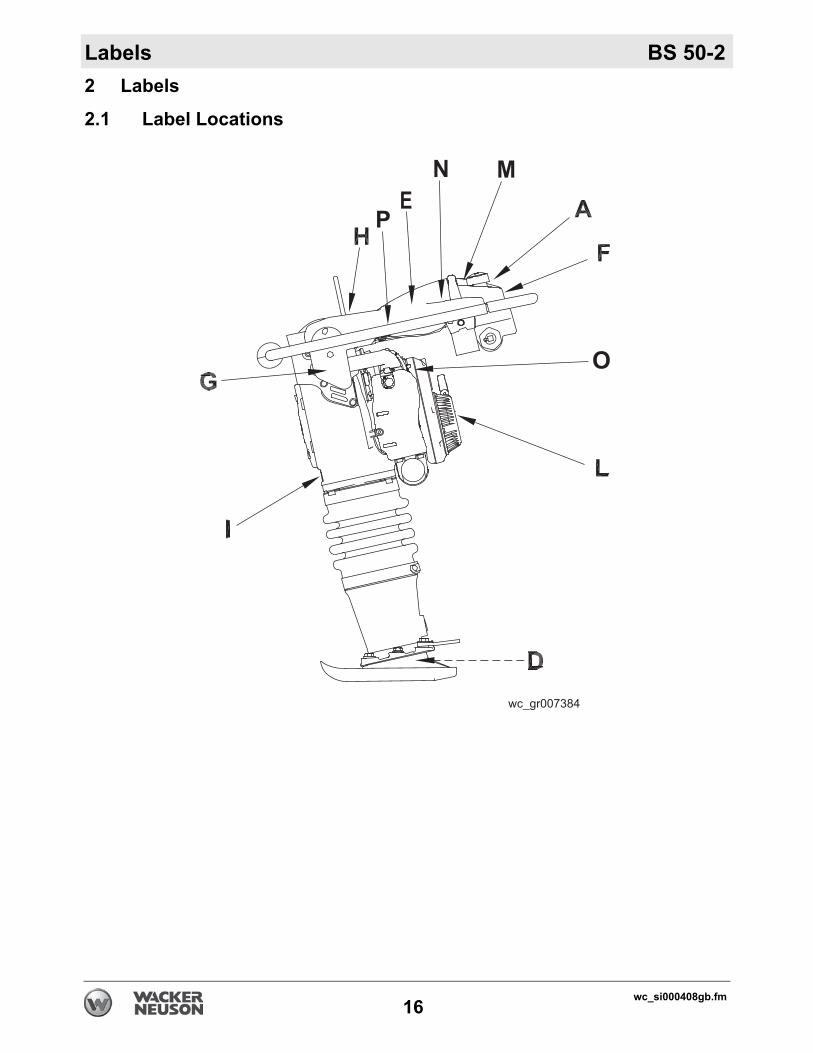
2 Labels2.1 Label Locations
wc_si000408gb.fm16
BS 50-2 Labels
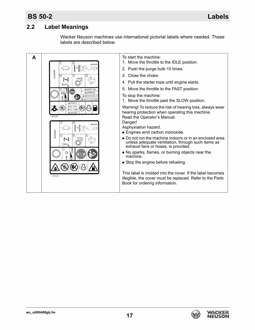
2.2 Label MeaningsWacker Neuson machines use international pictorial labels where needed. These labels are described below.
A To start the machine:1. Move the throttle to the IDLE position.2. Push the purge bulb 10 times.3. Close the choke.4. Pull the starter rope until engine starts.5. Move the throttle to the FAST position.To stop the machine:1. Move the throttle past the SLOW position.Warning! To reduce the risk of hearing loss, always wear hearing protection when operating this machine.Read the Operator’s Manual. Danger!Asphyxiation hazard.
Engines emit carbon monoxide. Do not run the machine indoors or in an enclosed area unless adequate ventilation, through such items as exhaust fans or hoses, is provided. No sparks, flames, or burning objects near the machine. Stop the engine before refueling.
This label is molded into the cover. If the label becomes illegible, the cover must be replaced. Refer to the Parts Book for ordering information.
wc_si000408gb.fm17
Labels BS 50-2
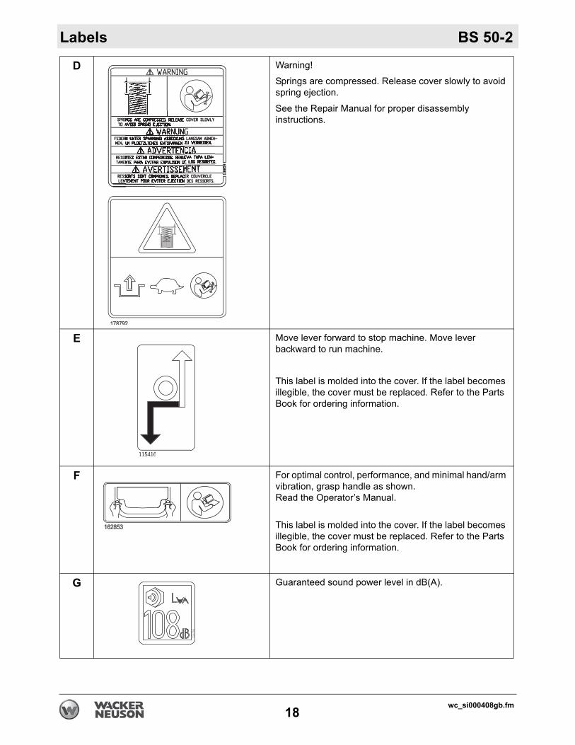
D Warning!
Springs are compressed. Release cover slowly to avoid spring ejection.
See the Repair Manual for proper disassembly instructions.
E Move lever forward to stop machine. Move lever backward to run machine.
This label is molded into the cover. If the label becomes illegible, the cover must be replaced. Refer to the Parts Book for ordering information.
F For optimal control, performance, and minimal hand/arm vibration, grasp handle as shown.Read the Operator’s Manual.
This label is molded into the cover. If the label becomes illegible, the cover must be replaced. Refer to the Parts Book for ordering information.
G Guaranteed sound power level in dB(A).
115416
wc_si000408gb.fm18
BS 50-2 Labels
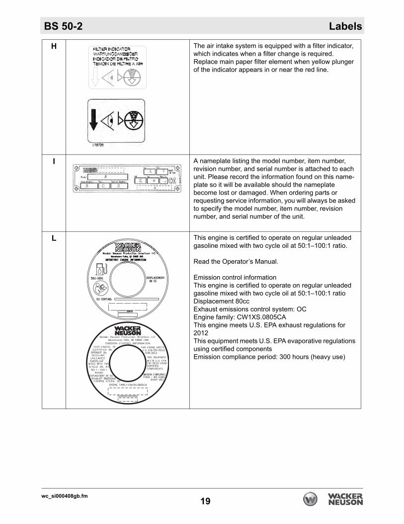
H The air intake system is equipped with a filter indicator, which indicates when a filter change is required. Replace main paper filter element when yellow plunger of the indicator appears in or near the red line.
I A nameplate listing the model number, item number, revision number, and serial number is attached to each unit. Please record the information found on this name-plate so it will be available should the nameplate become lost or damaged. When ordering parts or requesting service information, you will always be asked to specify the model number, item number, revision number, and serial number of the unit.
L This engine is certified to operate on regular unleaded gasoline mixed with two cycle oil at 50:1–100:1 ratio.
Read the Operator’s Manual.
Emission control informationThis engine is certified to operate on regular unleaded gasoline mixed with two cycle oil at 50:1–100:1 ratioDisplacement 80ccExhaust emissions control system: OCEngine family: CW1XS.0805CAThis engine meets U.S. EPA exhaust regulations for 2012This equipment meets U.S. EPA evaporative regulations using certified componentsEmission compliance period: 300 hours (heavy use)
wc_si000408gb.fm19
Labels BS 50-2
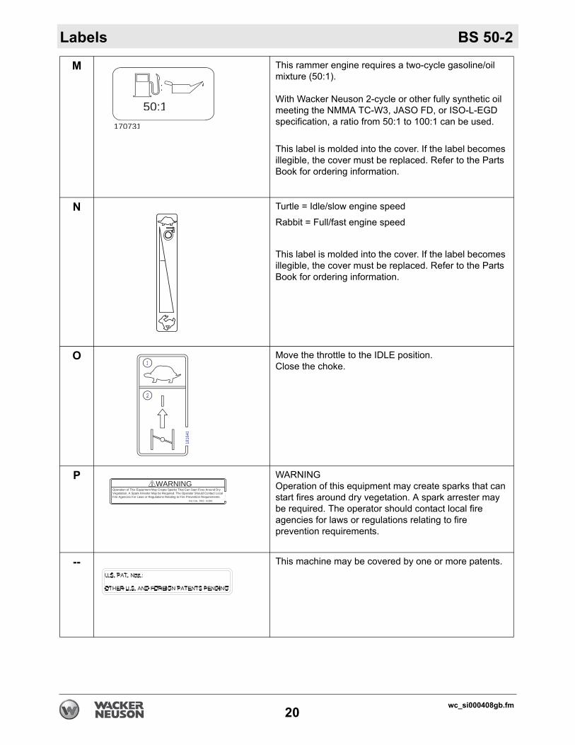
M This rammer engine requires a two-cycle gasoline/oil mixture (50:1).
With Wacker Neuson 2-cycle or other fully synthetic oil meeting the NMMA TC-W3, JASO FD, or ISO-L-EGD specification, a ratio from 50:1 to 100:1 can be used.
This label is molded into the cover. If the label becomes illegible, the cover must be replaced. Refer to the Parts Book for ordering information.
N Turtle = Idle/slow engine speed
Rabbit = Full/fast engine speed
This label is molded into the cover. If the label becomes illegible, the cover must be replaced. Refer to the Parts Book for ordering information.
O Move the throttle to the IDLE position.Close the choke.
P WARNINGOperation of this equipment may create sparks that can start fires around dry vegetation. A spark arrester may be required. The operator should contact local fire agencies for laws or regulations relating to fire prevention requirements.
-- This machine may be covered by one or more patents.
170731
50:1
:
1
1816
41
2
WARNINGOperation of This Equipment May Create Sparks That Can Start Fires Around DryVegetation. A Spark Arrestor May be Required. The Operator Should Contact LocalFire Agencies For Laws or Regulations Relating to Fire Prevention Requirements.
Per CAL. PRC. CODE
wc_si000408gb.fm20
BS 50-2 Lifting and Transporting
3 Lifting and Transporting3.1 Lifting the RammerRequirements Lifting device (crane or hoist) capable of supporting the rammer’s weight (see
the identification plate on the rammer)Lifting gear (hooks, slings, and/or chains) capable of supporting the rammer’s weightEngine stopped and cool to the touch
Procedure Perform the procedure below to lift the rammer.
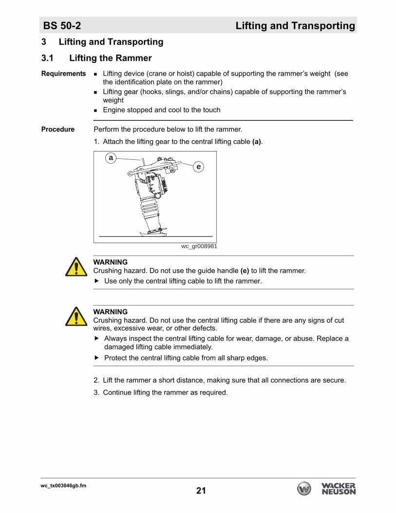
1. Attach the lifting gear to the central lifting cable (a).
2. Lift the rammer a short distance, making sure that all connections are secure.
3. Continue lifting the rammer as required.
wc_gr008981
ae
WARNINGCrushing hazard. Do not use the guide handle (e) to lift the rammer.
Use only the central lifting cable to lift the rammer.
WARNINGCrushing hazard. Do not use the central lifting cable if there are any signs of cut wires, excessive wear, or other defects.
Always inspect the central lifting cable for wear, damage, or abuse. Replace a damaged lifting cable immediately.Protect the central lifting cable from all sharp edges.
wc_tx003046gb.fm21
Lifting and Transporting BS 50-2
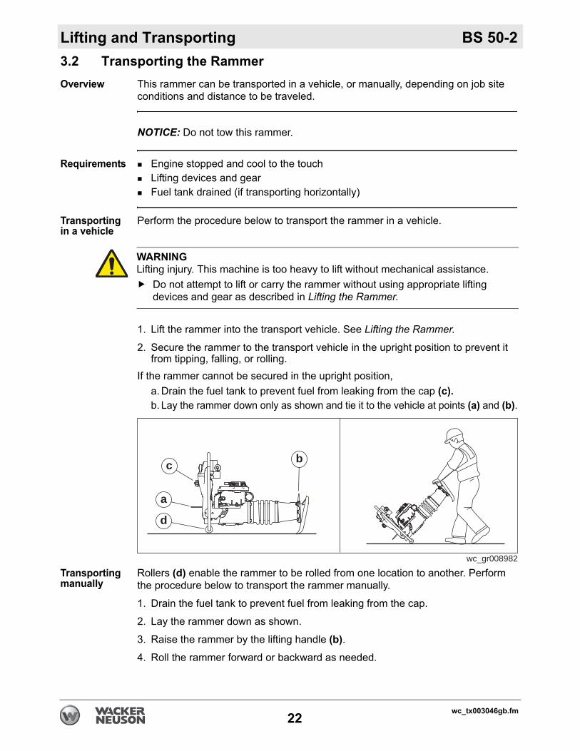
3.2 Transporting the RammerOverview This rammer can be transported in a vehicle, or manually, depending on job siteconditions and distance to be traveled.
NOTICE: Do not tow this rammer.
Requirements Engine stopped and cool to the touchLifting devices and gearFuel tank drained (if transporting horizontally)
Transporting in a vehicle
Perform the procedure below to transport the rammer in a vehicle.
1. Lift the rammer into the transport vehicle. See Lifting the Rammer.
2. Secure the rammer to the transport vehicle in the upright position to prevent it from tipping, falling, or rolling.
If the rammer cannot be secured in the upright position,a. Drain the fuel tank to prevent fuel from leaking from the cap (c).b. Lay the rammer down only as shown and tie it to the vehicle at points (a) and (b).
Transporting manually
Rollers (d) enable the rammer to be rolled from one location to another. Perform the procedure below to transport the rammer manually.
1. Drain the fuel tank to prevent fuel from leaking from the cap.
2. Lay the rammer down as shown.
3. Raise the rammer by the lifting handle (b).4. Roll the rammer forward or backward as needed.
WARNINGLifting injury. This machine is too heavy to lift without mechanical assistance.
Do not attempt to lift or carry the rammer without using appropriate lifting devices and gear as described in Lifting the Rammer.
a
d
c b
wc_gr008982
wc_tx003046gb.fm22
BS 50-2 Operation
4 Operation4.1 Preparing the Machine for First Use
Preparing for first use
To prepare your machine for first use:
1. Make sure all loose packaging materials have been removed from the machine.
2. Check the machine and its components for damage. If there is visible damage, do not operate the machine! Contact your Wacker Neuson dealer immediately for assistance.
3. Take inventory of all items included with the machine and verify that all loose components and fasteners are accounted for.
4. Attach component parts not already attached.
5. Add fluids as needed and applicable, including fuel, engine oil, and battery acid.
6. Move the machine to its operating location.
wc_tx003047gb.fm23
Operation BS 50-2
4.2 Recommended FuelOverview This rammer engine does not have a separate lubrication system. Instead, itrequires a two-cycle gasoline/oil mixture. Two-cycle oil must be mixed with the gasoline so that the engine is lubricated as it burns fuel.
NOTICE: Use only the recommended gasoline/oil mixture to fuel this machine. Using gasoline alone will severely damage the engine.
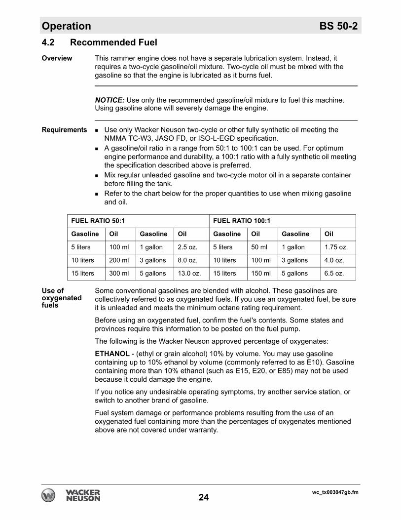
Requirements Use only Wacker Neuson two-cycle or other fully synthetic oil meeting the NMMA TC-W3, JASO FD, or ISO-L-EGD specification.A gasoline/oil ratio in a range from 50:1 to 100:1 can be used. For optimum engine performance and durability, a 100:1 ratio with a fully synthetic oil meeting the specification described above is preferred.Mix regular unleaded gasoline and two-cycle motor oil in a separate container before filling the tank.Refer to the chart below for the proper quantities to use when mixing gasoline and oil.
Use of oxygenated fuels
Some conventional gasolines are blended with alcohol. These gasolines are collectively referred to as oxygenated fuels. If you use an oxygenated fuel, be sure it is unleaded and meets the minimum octane rating requirement.
Before using an oxygenated fuel, confirm the fuel's contents. Some states and provinces require this information to be posted on the fuel pump.
The following is the Wacker Neuson approved percentage of oxygenates:
ETHANOL - (ethyl or grain alcohol) 10% by volume. You may use gasoline containing up to 10% ethanol by volume (commonly referred to as E10). Gasoline containing more than 10% ethanol (such as E15, E20, or E85) may not be used because it could damage the engine.
If you notice any undesirable operating symptoms, try another service station, or switch to another brand of gasoline.
Fuel system damage or performance problems resulting from the use of an oxygenated fuel containing more than the percentages of oxygenates mentioned above are not covered under warranty.
FUEL RATIO 50:1 FUEL RATIO 100:1
Gasoline Oil Gasoline Oil Gasoline Oil Gasoline Oil
5 liters 100 ml 1 gallon 2.5 oz. 5 liters 50 ml 1 gallon 1.75 oz.
10 liters 200 ml 3 gallons 8.0 oz. 10 liters 100 ml 3 gallons 4.0 oz.
15 liters 300 ml 5 gallons 13.0 oz. 15 liters 150 ml 5 gallons 6.5 oz.
wc_tx003047gb.fm24
BS 50-2 Operation
4.3 Refueling the MachineRequirements Machine shut downEngine coolMachine standing upright on the ramming shoeFresh, clean fuel supply
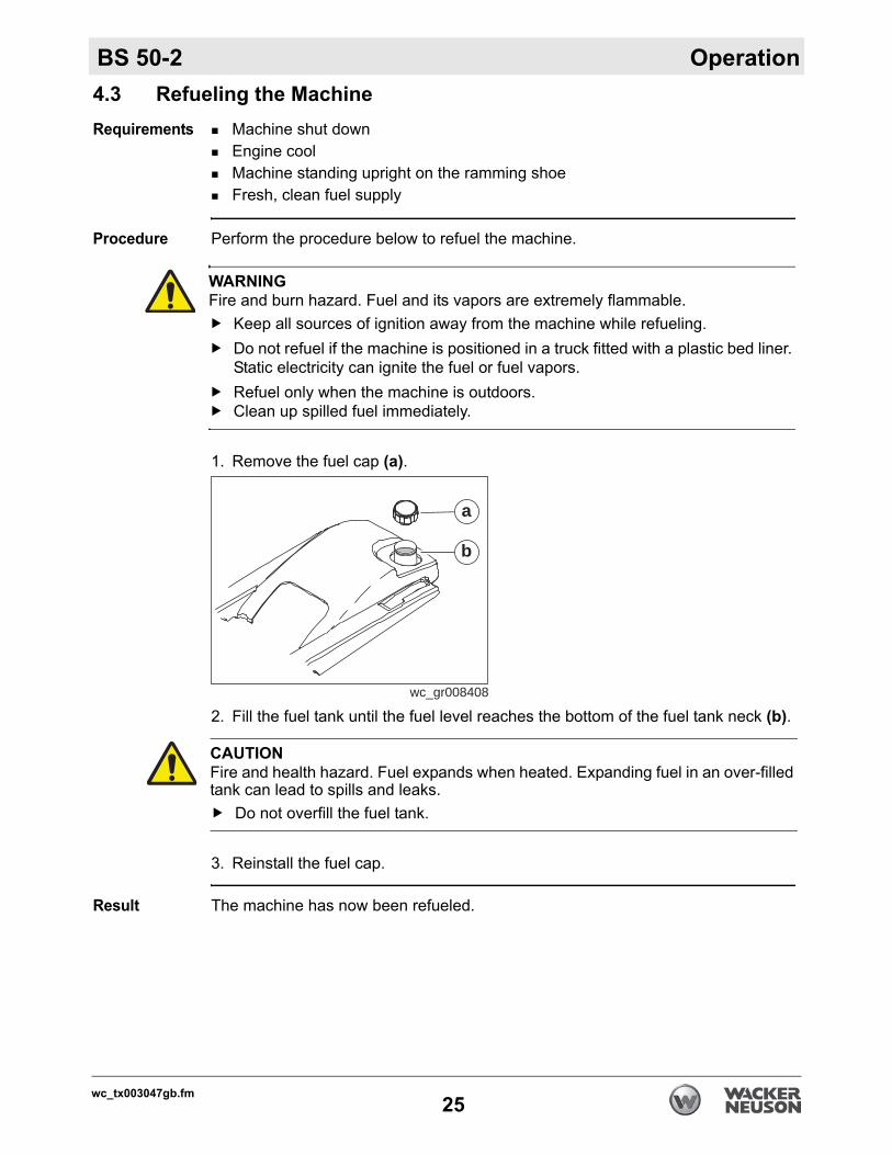
Procedure Perform the procedure below to refuel the machine.
1. Remove the fuel cap (a).
2. Fill the fuel tank until the fuel level reaches the bottom of the fuel tank neck (b).
3. Reinstall the fuel cap.
Result The machine has now been refueled.
WARNINGFire and burn hazard. Fuel and its vapors are extremely flammable.
Keep all sources of ignition away from the machine while refueling.Do not refuel if the machine is positioned in a truck fitted with a plastic bed liner. Static electricity can ignite the fuel or fuel vapors.Refuel only when the machine is outdoors.Clean up spilled fuel immediately.
wc_gr008408
a
b
CAUTIONFire and health hazard. Fuel expands when heated. Expanding fuel in an over-filled tank can lead to spills and leaks.
Do not overfill the fuel tank.
wc_tx003047gb.fm25
Operation BS 50-2
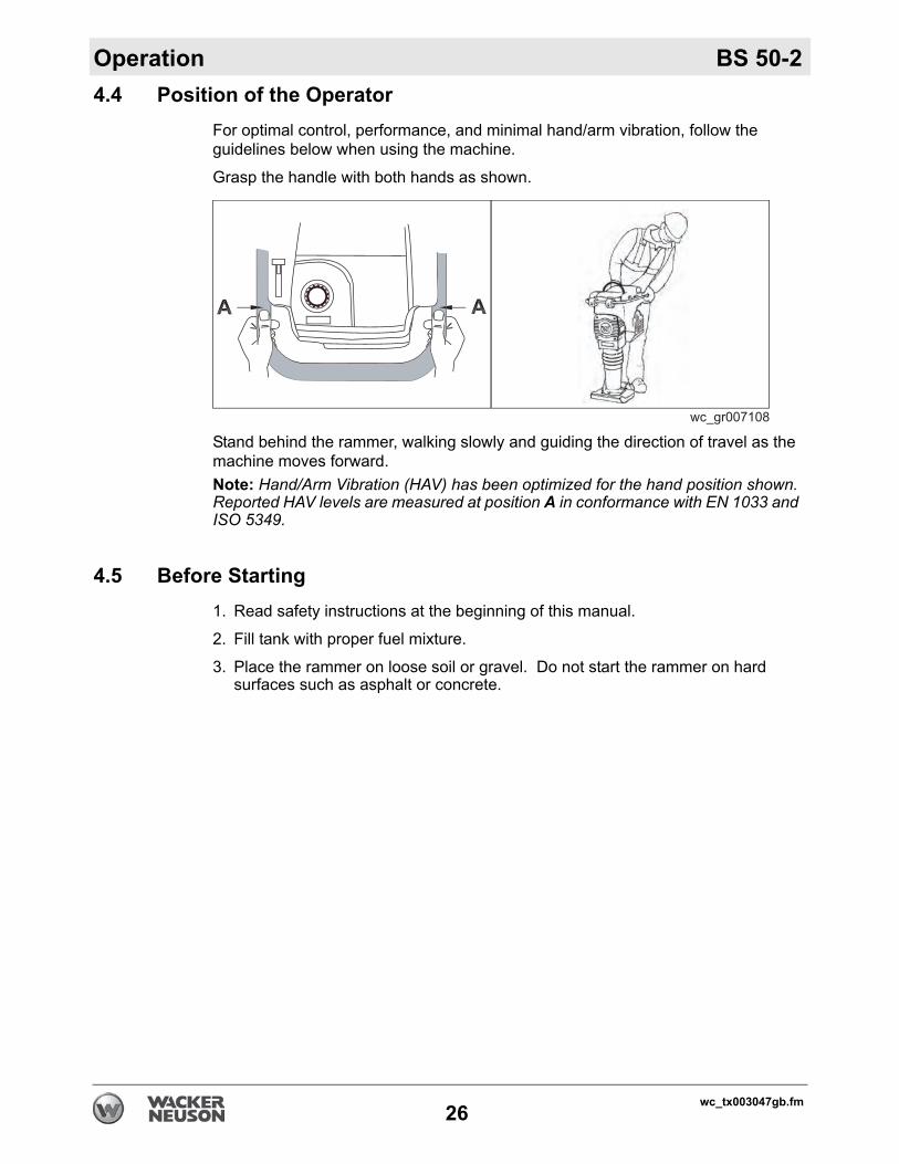
4.4 Position of the OperatorFor optimal control, performance, and minimal hand/arm vibration, follow the guidelines below when using the machine.
Grasp the handle with both hands as shown.
Stand behind the rammer, walking slowly and guiding the direction of travel as the machine moves forward.Note: Hand/Arm Vibration (HAV) has been optimized for the hand position shown. Reported HAV levels are measured at position A in conformance with EN 1033 and ISO 5349.
4.5 Before Starting1. Read safety instructions at the beginning of this manual.
2. Fill tank with proper fuel mixture.
3. Place the rammer on loose soil or gravel. Do not start the rammer on hard surfaces such as asphalt or concrete.
wc_tx003047gb.fm26
BS 50-2 Operation
wc_tx003047gb.fm
4.6 Starting, Operating, and Stopping the MachineRequirements Rammer is in serviceable condition and has been properly maintained
There is fuel in the tank
Starting the machine
Perform the procedure below to start the machine.
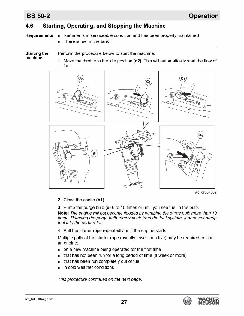
1. Move the throttle to the idle position (c2). This will automatically start the flow of fuel.
2. Close the choke (b1).3. Pump the purge bulb (e) 6 to 10 times or until you see fuel in the bulb.Note: The engine will not become flooded by pumping the purge bulb more than 10 times. Pumping the purge bulb removes air from the fuel system. It does not pump fuel into the carburetor.
4. Pull the starter rope repeatedly until the engine starts. Multiple pulls of the starter rope (usually fewer than five) may be required to start an engine:
on a new machine being operated for the first timethat has not been run for a long period of time (a week or more)that has been run completely out of fuelin cold weather conditions
This procedure continues on the next page.
27
Operation BS 50-2
Continued from the previous page.Operating the machine
Perform the procedure below to operate the rammer.
1. Move the throttle to the full position (c3). The choke will open automatically.
2. Guide the rammer’s direction of travel. Allow the rammer to pull itself forward. Do not try to overpower the rammer.
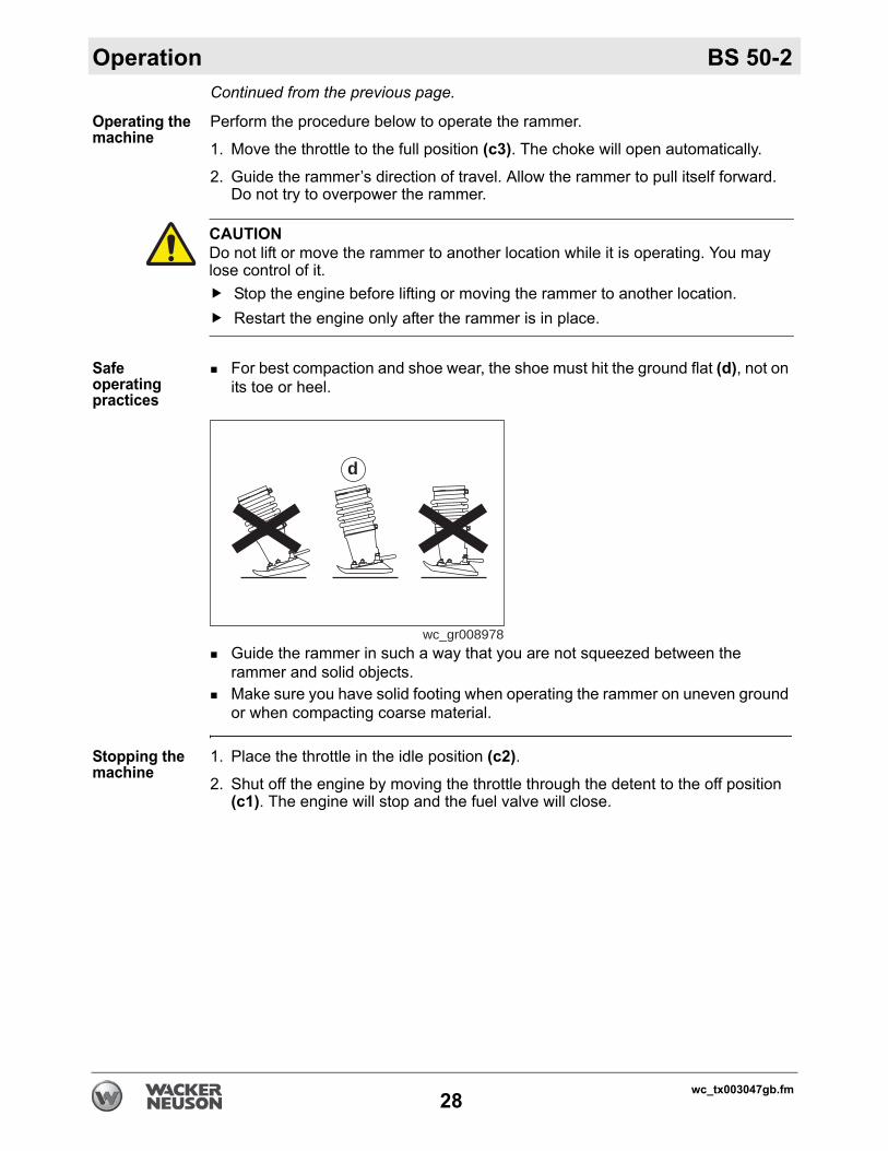
Safe operating practices
For best compaction and shoe wear, the shoe must hit the ground flat (d), not on its toe or heel.
Guide the rammer in such a way that you are not squeezed between the rammer and solid objects.Make sure you have solid footing when operating the rammer on uneven ground or when compacting coarse material.
Stopping the machine
1. Place the throttle in the idle position (c2).2. Shut off the engine by moving the throttle through the detent to the off position
(c1). The engine will stop and the fuel valve will close.
CAUTIONDo not lift or move the rammer to another location while it is operating. You may lose control of it.
Stop the engine before lifting or moving the rammer to another location. Restart the engine only after the rammer is in place.
wc_gr008978
d
wc_tx003047gb.fm28
BS 50-2 Operation
4.7 Emergency Shutdown ProcedureProcedure If a breakdown or accident occurs while the machine is operating, follow theprocedure below:
1. Reduce engine speed to idle.
2. Stop the engine.
3. Close the fuel valve.
4. Contact the rental yard or machine owner for further instructions.
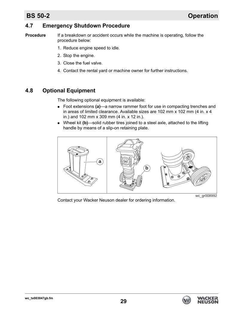
4.8 Optional EquipmentThe following optional equipment is available:
Foot extensions (a)—a narrow rammer foot for use in compacting trenches and in areas of limited clearance. Available sizes are 102 mm x 102 mm (4 in. x 4 in.) and 102 mm x 309 mm (4 in. x 12 in.).Wheel kit (b)—solid rubber tires joined to a steel axle, attached to the lifting handle by means of a slip-on retaining plate.
Contact your Wacker Neuson dealer for ordering information.
wc_gr008992
ab
wc_tx003047gb.fm29
Maintenance BS 50-2
5 Maintenance5.1 Maintaining the Emission Control SystemNormal maintenance, replacement, or repair of emission control devices and systems may be performed by any repair establishment or individual; however, warranty repairs must be performed by a dealer/service center authorized by Wacker Neuson. The use of service parts that are not equivalent in performance and durability to authorized parts may impair the effectiveness of the emission control system and may have a bearing on the outcome of a warranty claim.
WARNINGA poorly maintained machine can malfunction, causing injuries or permanent damage to the machine.
Keep the machine in safe operating condition by performing periodic mainte-nance and making repairs as needed.
wc_tx003048gb.fm30
BS 50-2 Maintenance
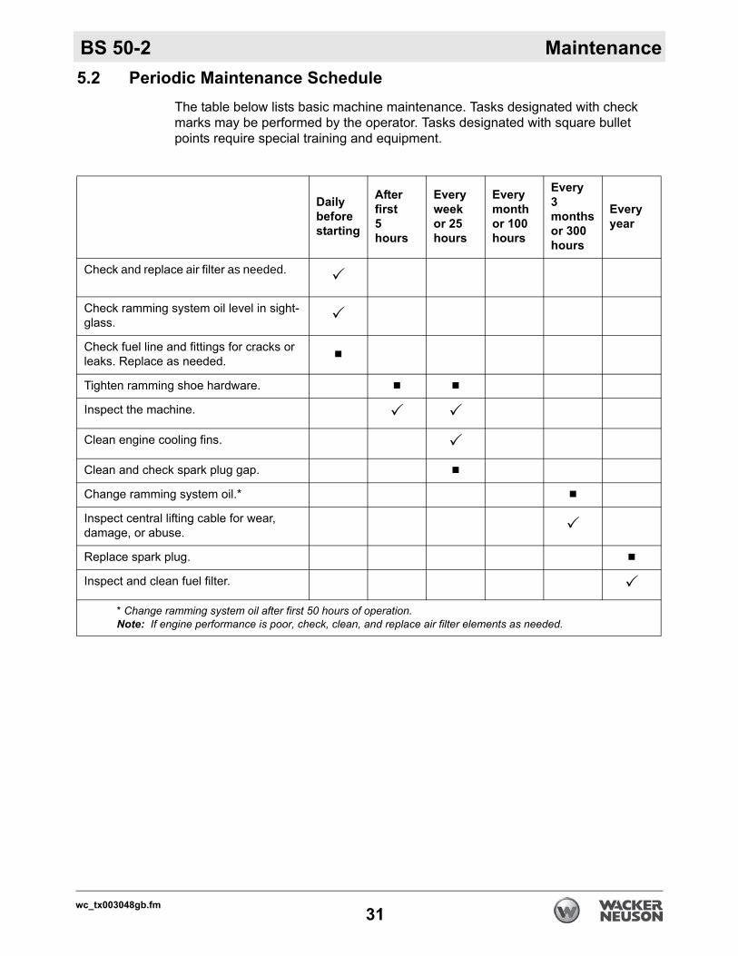
5.2 Periodic Maintenance ScheduleThe table below lists basic machine maintenance. Tasks designated with check marks may be performed by the operator. Tasks designated with square bullet points require special training and equipment.
Dailybeforestarting
Afterfirst5hours
Everyweekor 25hours
Everymonthor 100hours
Every3 monthsor 300hours
Everyyear
Check and replace air filter as needed. as needed.
Check ramming system oil level in sight-glass.
Check fuel line and fittings for cracks or leaks. Replace as needed.
Tighten ramming shoe hardware.
Inspect the machine.
Clean engine cooling fins.
Clean and check spark plug gap.
Change ramming system oil.*
Inspect central lifting cable for wear, damage, or abuse.
Replace spark plug.
Inspect and clean fuel filter.
* Change ramming system oil after first 50 hours of operation.Note: If engine performance is poor, check, clean, and replace air filter elements as needed.
wc_tx003048gb.fm31
Maintenance BS 50-2
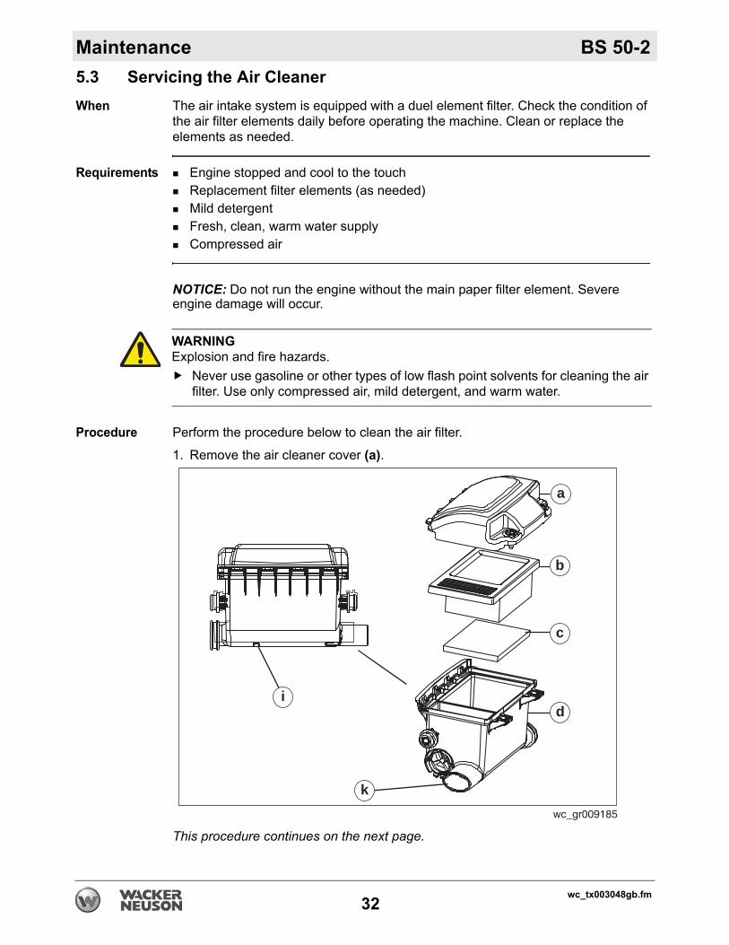
5.3 Servicing the Air CleanerWhen The air intake system is equipped with a duel element filter. Check the condition ofthe air filter elements daily before operating the machine. Clean or replace the elements as needed.
Requirements Engine stopped and cool to the touchReplacement filter elements (as needed)Mild detergentFresh, clean, warm water supplyCompressed air
NOTICE: Do not run the engine without the main paper filter element. Severe engine damage will occur.
Procedure Perform the procedure below to clean the air filter.
1. Remove the air cleaner cover (a).
This procedure continues on the next page.
WARNINGExplosion and fire hazards.
Never use gasoline or other types of low flash point solvents for cleaning the air filter. Use only compressed air, mild detergent, and warm water.
wc_gr009185
i
k
d
c
b
a
wc_tx003048gb.fm32
BS 50-2 Maintenance
Continued from the previous page.2. Remove the min paper filter element (b) and prefilter (c) and inspect them for holes or tears. Replace the elements if they are damaged.a. Main paper filter element (b): Replace the main paper filter element if it
appears heavily soiled.b. Prefilter (c): Clean the prefilter with low-pressure compressed air. If the
prefilter is extremely soiled, wash it in a solution of mild detergent and warm water. Rinse the prefilter thoroughly in clean water. Allow it to dry thoroughly before reinstalling it.
Note: Do not oil the prefilter.
3. Wipe out the filter housing (d) with a clean cloth. Do not use compressed air.
NOTICE: Do not allow dirt to get into the engine intake port (k) while cleaning. Damage to engine will result.
4. Check that the precleaner debris ejector slot (i) is clear.
5. Reinstall the air cleaner cover.
Result The air cleaner has now been serviced.
wc_tx003048gb.fm33
Maintenance BS 50-2
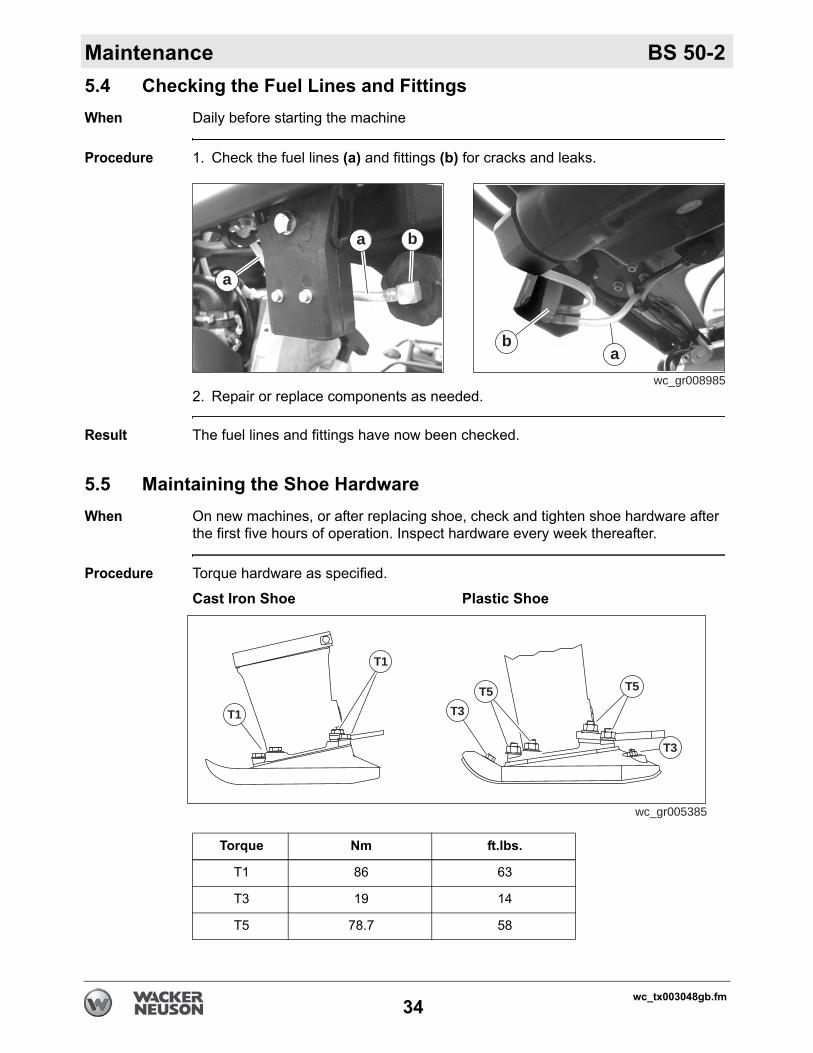
5.4 Checking the Fuel Lines and FittingsWhen Daily before starting the machineProcedure 1. Check the fuel lines (a) and fittings (b) for cracks and leaks.
2. Repair or replace components as needed.
Result The fuel lines and fittings have now been checked.
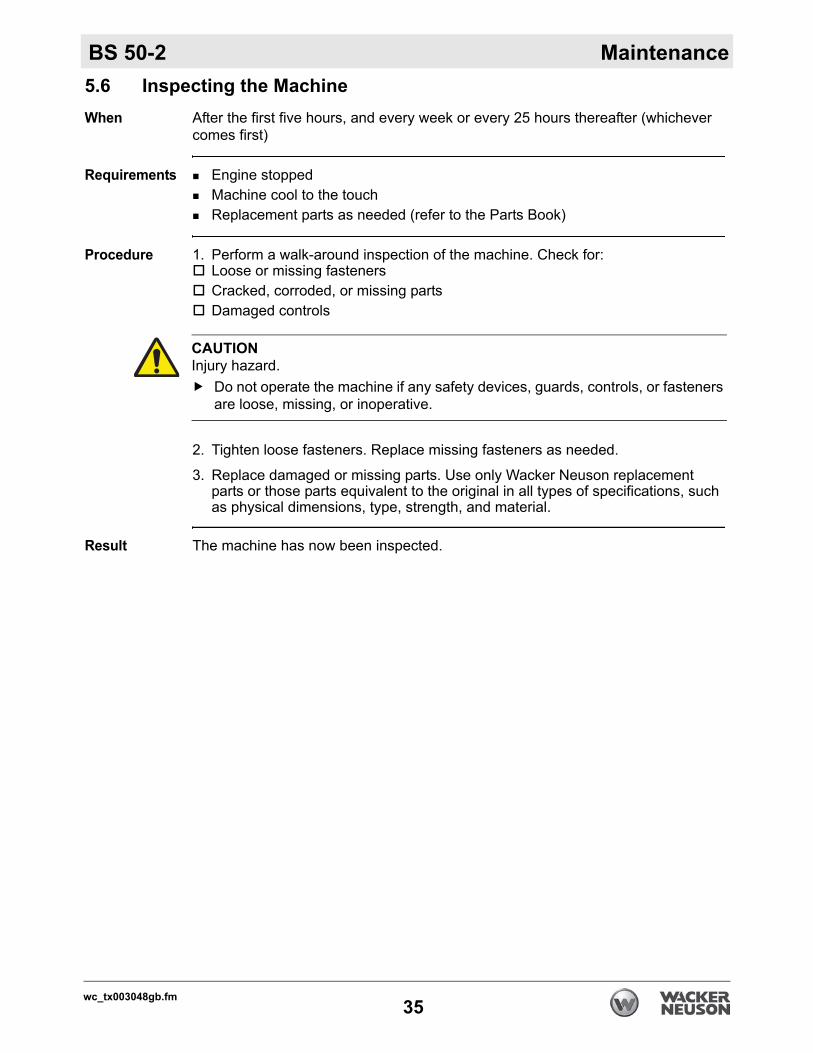
5.5 Maintaining the Shoe HardwareWhen On new machines, or after replacing shoe, check and tighten shoe hardware after
the first five hours of operation. Inspect hardware every week thereafter.
Procedure Torque hardware as specified.
Cast Iron Shoe Plastic Shoe
wc_gr008985
a
a
b
ab
T1
T1
T5
T3
T3T5
wc_gr005385
Torque Nm ft.lbs.
T1 86 63
T3 19 14
T5 78.7 58
wc_tx003048gb.fm34
BS 50-2 Maintenance
5.6 Inspecting the MachineWhen After the first five hours, and every week or every 25 hours thereafter (whichevercomes first)
Requirements Engine stoppedMachine cool to the touchReplacement parts as needed (refer to the Parts Book)
Procedure 1. Perform a walk-around inspection of the machine. Check for:Loose or missing fastenersCracked, corroded, or missing partsDamaged controls
2. Tighten loose fasteners. Replace missing fasteners as needed.
3. Replace damaged or missing parts. Use only Wacker Neuson replacement parts or those parts equivalent to the original in all types of specifications, such as physical dimensions, type, strength, and material.
Result The machine has now been inspected.
CAUTIONInjury hazard.
Do not operate the machine if any safety devices, guards, controls, or fasteners are loose, missing, or inoperative.
wc_tx003048gb.fm35
Maintenance BS 50-2
5.7 Cleaning the Engine Cooling FinsWhen Every week, or every 25 hours (whichever comes first)Background Clean engine cooling fins allow fresh air to freely circulate around the combustion chamber. Free air circulation is necessary to prevent the engine from overheating.
Requirements Engine stopped and cool to the touchCompressed air
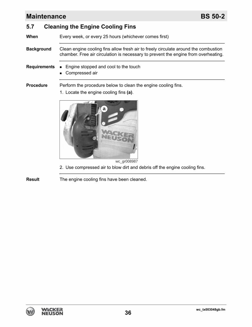
Procedure Perform the procedure below to clean the engine cooling fins.1. Locate the engine cooling fins (a).
2. Use compressed air to blow dirt and debris off the engine cooling fins.
Result The engine cooling fins have been cleaned.
wc_gr008987
a
wc_tx003048gb.fm36
BS 50-2 Maintenance
5.8 Cleaning and Checking the Spark PlugWhen Every week, or every 25 hours (whichever comes first)Requirements Engine stopped and cool to the touchSpark plug wrenchSpark plug gap toolWire brushReplacement spark plug as needed (see Technical Data)
Procedure Perform the procedure below to clean and check the spark plug.
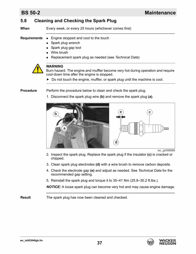
1. Disconnect the spark plug wire (b) and remove the spark plug (a).
2. Inspect the spark plug. Replace the spark plug if the insulator (c) is cracked or chipped.
3. Clean spark plug electrodes (d) with a wire brush to remove carbon deposits.
4. Check the electrode gap (e) and adjust as needed. See Technical Data for the recommended gap setting.
5. Reinstall the spark plug and torque it to 35–41 Nm (25.8–30.2 ft.lbs.).
NOTICE: A loose spark plug can become very hot and may cause engine damage.
Result The spark plug has now been cleaned and checked.
WARNINGBurn hazard. The engine and muffler become very hot during operation and require cool-down time after the engine is stopped.
Do not touch the engine, muffler, or spark plug until the machine is cool.
wc_gr008988
a
b
d
ce
wc_tx003048gb.fm37
Maintenance BS 50-2
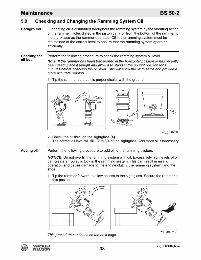
5.9 Checking and Changing the Ramming System OilBackground Lubricating oil is distributed throughout the ramming system by the vibrating actionof the rammer. Holes drilled in the piston carry oil from the bottom of the rammer to the crankcase as the rammer operates. Oil in the ramming system must be maintained at the correct level to ensure that the ramming system operates efficiently.
Checking the oil level
Perform the following procedure to check the ramming system oil level.Note: If the rammer has been transported in the horizontal position or has recently been used, place it upright and allow it to stand in the upright position for 15 minutes before checking the oil level. This will allow the oil to settle and provide a more accurate reading.
1. Tip the rammer so that it is perpendicular with the ground.
2. Check the oil through the sightglass (a).The correct oil level will fill 1/2 to 3/4 of the sightglass. Add more oil if necessary.
Adding oil Perform the following procedure to add oil to the ramming system.
NOTICE: Do not overfill the ramming system with oil. Excessively high levels of oil can create a hydraulic lock in the ramming system. This can result in erratic operation and cause damage to the engine clutch, the ramming system, and the shoe.
1. Tip the rammer forward to allow access to the sightglass. Secure the rammer in this position.
This procedure continues on the next page.
wc_tx003048gb.fm38
BS 50-2 Maintenance
Continued from the previous page.2. Remove the sightglass. Clean the threads of the sightglass, then wrap the threads with Teflon tape.
3. Add oil to the machine through the sightglass opening in the housing.
4. Reinstall the sightglass, but do not torque it at this time.
5. Stand the machine upright and check the oil level.
6. Add oil as needed so that it fills 1/2 to 3/4 of the sightglass.
7. Torque the sightglass to 9 Nm (6 ft.lbs.).
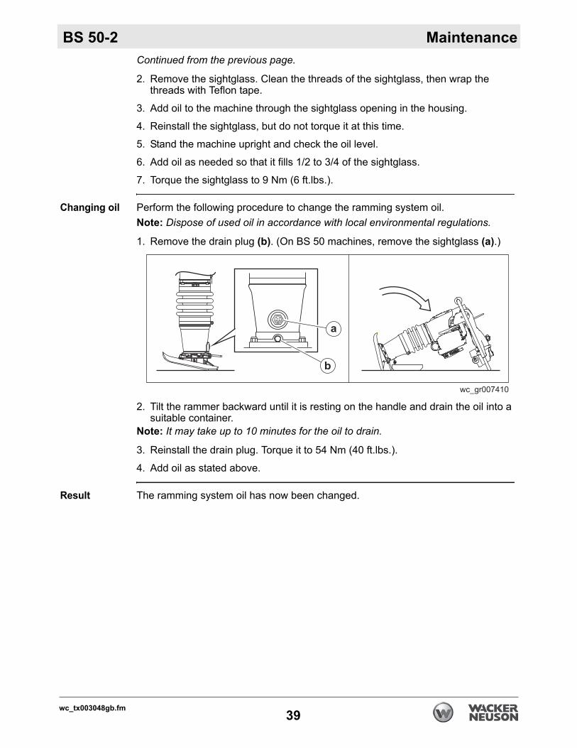
Changing oil Perform the following procedure to change the ramming system oil.Note: Dispose of used oil in accordance with local environmental regulations.
1. Remove the drain plug (b). (On BS 50 machines, remove the sightglass (a).)
2. Tilt the rammer backward until it is resting on the handle and drain the oil into a suitable container.
Note: It may take up to 10 minutes for the oil to drain.
3. Reinstall the drain plug. Torque it to 54 Nm (40 ft.lbs.).
4. Add oil as stated above.
Result The ramming system oil has now been changed.
wc_tx003048gb.fm39
Maintenance BS 50-2
5.10 Adjusting the Idle SpeedRequirements TachometerPhillips screwdriver
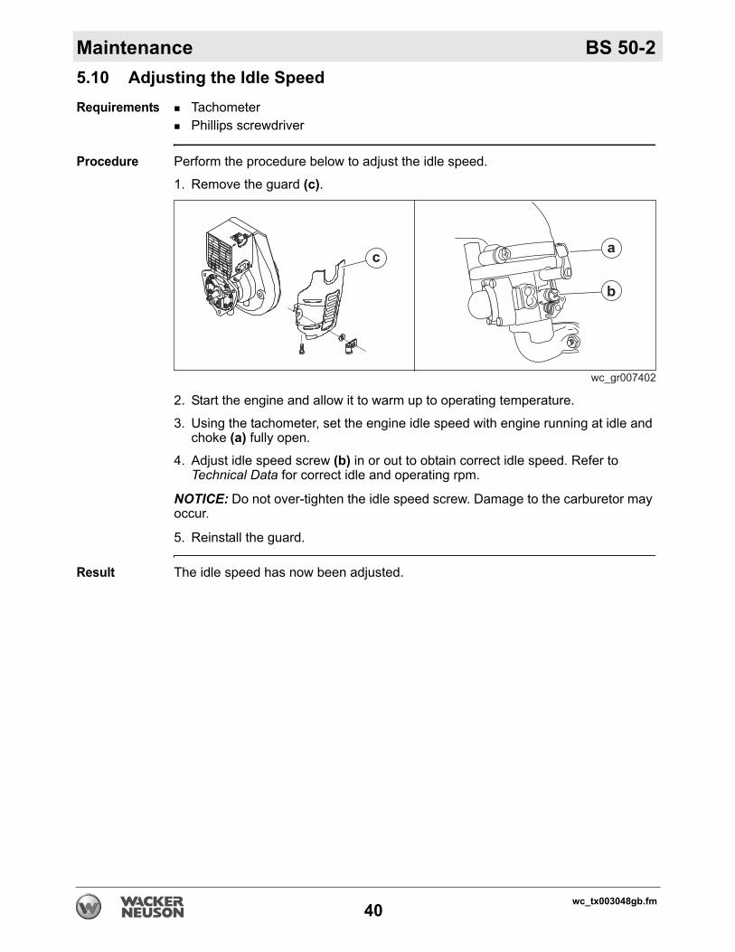
Procedure Perform the procedure below to adjust the idle speed.
1. Remove the guard (c).
2. Start the engine and allow it to warm up to operating temperature.
3. Using the tachometer, set the engine idle speed with engine running at idle and choke (a) fully open.
4. Adjust idle speed screw (b) in or out to obtain correct idle speed. Refer to Technical Data for correct idle and operating rpm.
NOTICE: Do not over-tighten the idle speed screw. Damage to the carburetor may occur.
5. Reinstall the guard.
Result The idle speed has now been adjusted.
wc_tx003048gb.fm40
BS 50-2 Maintenance
5.11 Inspecting and Cleaning the Fuel FilterWhen Every year or every 1200 hours (whichever comes first)Requirements Engine stoppedFuel tank emptyClean, dry, lint-free clothReplacement fuel filter (as needed)
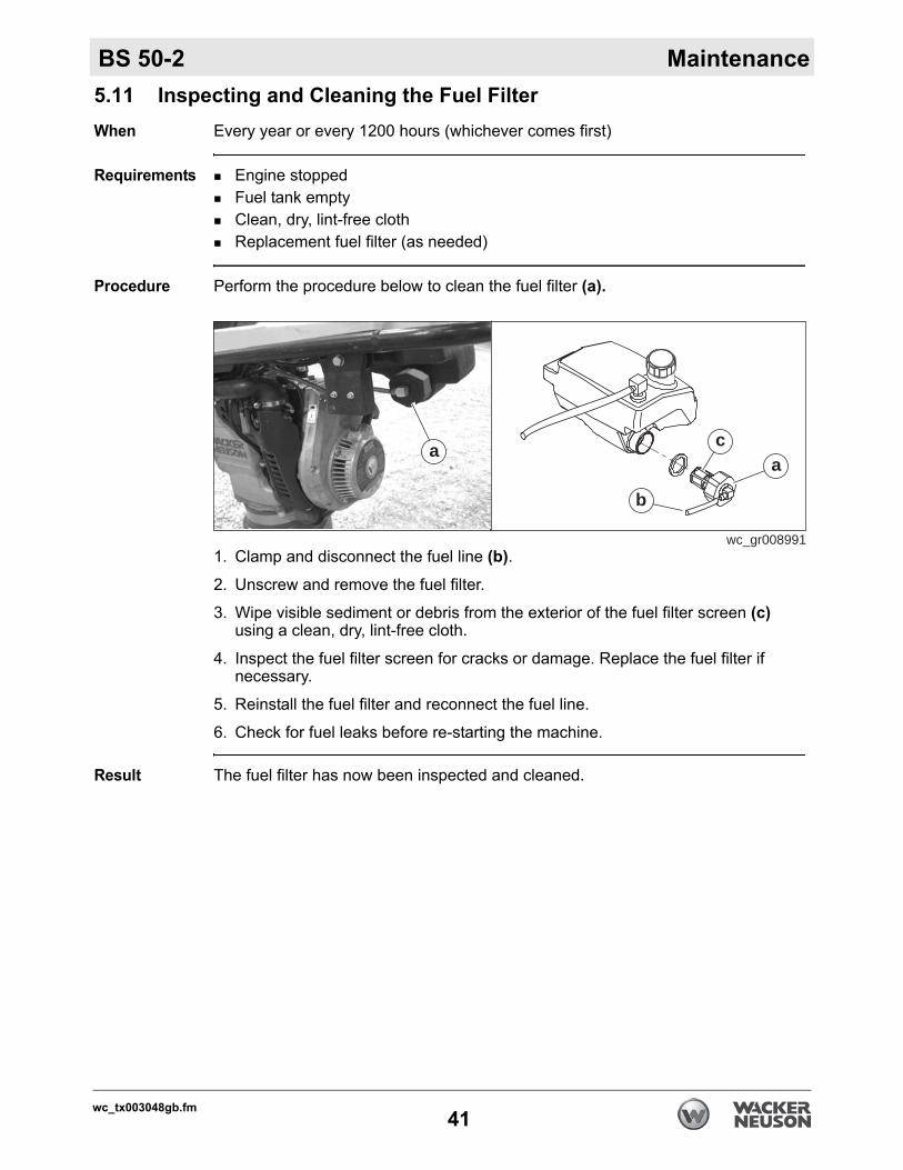
Procedure Perform the procedure below to clean the fuel filter (a).
1. Clamp and disconnect the fuel line (b).2. Unscrew and remove the fuel filter.
3. Wipe visible sediment or debris from the exterior of the fuel filter screen (c) using a clean, dry, lint-free cloth.
4. Inspect the fuel filter screen for cracks or damage. Replace the fuel filter if necessary.
5. Reinstall the fuel filter and reconnect the fuel line.
6. Check for fuel leaks before re-starting the machine.
Result The fuel filter has now been inspected and cleaned.
wc_gr008991
aa
b
c
wc_tx003048gb.fm41
Maintenance BS 50-2
5.12 Long-Term StorageIntroduction This machine requires preventive maintenance before long-term storage.Performing preventive maintenance helps to preserve machine components and ensures that the machine will be ready for future use.
When Prepare your machine for extended storage if it will not be operated for 30 days or more.
Preparing for storage
Follow the procedures below to prepare your machine for storage.
1. Complete any needed repairs.
2. Replenish or change oils (engine, ramming sytem, etc.) per the intervals specified in the Periodic Maintenance table.
3. 4-cycle machines only: Consult the engine owner’s manual for instructions on preparing the engine for storage.
Stabilizing the fuel
After completing the procedures listed above, fill the fuel tank completely and add a high-quality stabilizer to the fuel.
Choose a stabilizer that includes cleaning agents and additives designed to coat/protect the cylinder walls.Make sure the stabilizer you use is compatible with the fuel in your area, fuel type, grade and temperature range. Do not add extra alcohol to fuels which already contain it (for example, E10).Add the correct amount of stabilizer per the manufacturer’s recommendations.
Storing the machine
Perform these remaining steps to store your machine.
1. Wash the machine and allow it to dry.
2. Move the machine to a clean, dry, secure storage location.
3. Secure the machine in an upright position.
4. Cover the machine.
wc_tx003048gb.fm42
BS 50-2 Maintenance
5.13 Machine Disposal / DecommissioningIntroduction This machine must be properly decommissioned at the end of its service life.Responsible disposal of recyclable components, such as plastic and metal, ensures that these materials can be reused—conserving landfill space and valuable natural resources.
Responsible disposal also prevents toxic chemicals and materials from harming the environment. The operating fluids in this machine, including fuel, engine oil, ramming system oil, and grease, may be considered hazardous waste in many areas. Before decommissioning this machine, read and follow local safety and environmental regulations pertaining to the disposal of construction equipment.
Preparation Perform the following tasks to prepare the machine for disposal.Move the machine to a protected location where it will not pose any safety hazards and cannot be accessed by unauthorized individuals.Ensure that the machine cannot be operated from the time of final shutdown to disposal.Drain all fluids, including fuel, engine oil, and ramming system oil. Seal any fluid leaks.
Disposal Perform the following tasks to dispose of the machine.Disassemble the machine and separate all parts by material type.Dispose of recyclable parts as specified by local regulations.Dispose of all non-hazardous components that cannot be recycled.Dispose of waste fuel, oil, and grease in accordance with local environmental protection regulations.
wc_tx003048gb.fm43
wc_tx003049gb.fm44
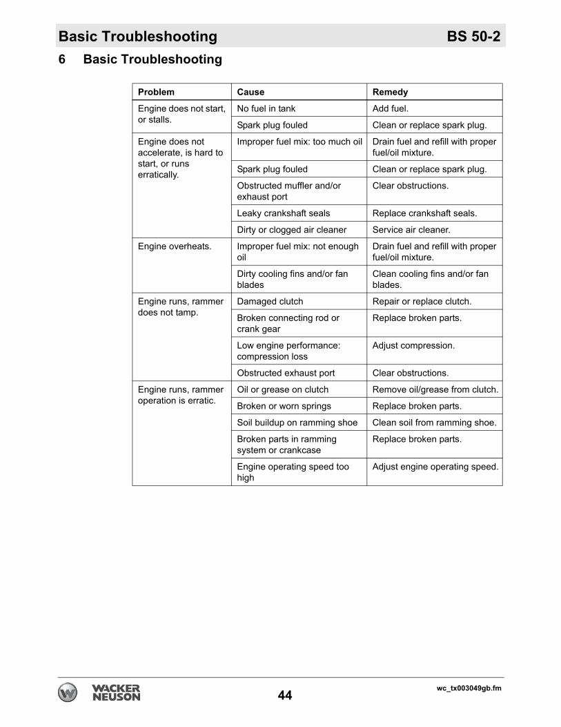
Basic Troubleshooting BS 50-26 Basic Troubleshooting
Problem Cause Remedy
Engine does not start, or stalls.
No fuel in tank Add fuel.
Spark plug fouled Clean or replace spark plug.
Engine does not accelerate, is hard to start, or runs erratically.
Improper fuel mix: too much oil Drain fuel and refill with proper fuel/oil mixture.
Spark plug fouled Clean or replace spark plug.
Obstructed muffler and/or exhaust port
Clear obstructions.
Leaky crankshaft seals Replace crankshaft seals.
Dirty or clogged air cleaner Service air cleaner.
Engine overheats. Improper fuel mix: not enough oil
Drain fuel and refill with proper fuel/oil mixture.
Dirty cooling fins and/or fan blades
Clean cooling fins and/or fan blades.
Engine runs, rammer does not tamp.
Damaged clutch Repair or replace clutch.
Broken connecting rod or crank gear
Replace broken parts.
Low engine performance: compression loss
Adjust compression.
Obstructed exhaust port Clear obstructions.
Engine runs, rammer operation is erratic.
Oil or grease on clutch Remove oil/grease from clutch.
Broken or worn springs Replace broken parts.
Soil buildup on ramming shoe Clean soil from ramming shoe.
Broken parts in ramming system or crankcase
Replace broken parts.
Engine operating speed too high
Adjust engine operating speed.
BS 50-2 Technical Data
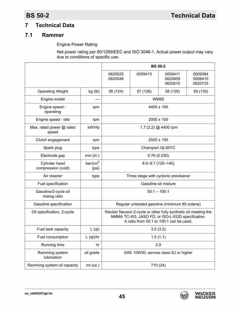
7 Technical Data7.1 RammerEngine Power Rating
Net power rating per 80/1269/EEC and ISO 3046-1. Actual power output may vary due to conditions of specific use.
BS 50-2
06200250620048
0009413 000941106206090620610
000938400094100620733
Operating Weight kg (lb) 56 (124) 57 (126) 58 (129) 59 (130)
Engine model — WM80
Engine speed -operating
rpm 4400 ± 100
Engine speed - idle rpm 2000 ± 100
Max. rated power @ rated speed
kW/Hp 1.7 (2.2) @ 4400 rpm
Clutch engagement rpm 2500 ± 100
Spark plug type Champion QL95YC
Electrode gap mm (in.) 0.76 (0.030)
Cylinder head compression (cold)
bar/cm3
(psi)8.0–9.7 (120–140)
Air cleaner type Three stage with cyclonic precleaner
Fuel specification Gasoline-oil mixture
Gasoline/2-cycle oilmixing ratio
50:1 – 100:1
Gasoline specification Regular unleaded gasoline (minimum 85 octane)
Oil specification, 2-cycle Wacker Neuson 2-cycle or other fully synthetic oil meeting the NMMA TC-W3, JASO FD, or ISO-L-EGD specification.
A ratio from 50:1 to 100:1 can be used.
Fuel tank capacity L (qt) 3.0 (3.2)
Fuel consumption L (qt)/hr 1.0 (1.1)
Running time hr 2.9
Ramming systemlubrication
oil grade SAE 10W30, service class SJ or higher
Ramming system oil capacity ml (oz.) 710 (24)
wc_td000287gb.fm45
Technical Data BS 50-2
7.2 Sound MeasurementsProducts are tested for sound pressure level in accordance with EN ISO 11204. Sound power level is tested in accordance with European Directive 2000/14/EC - Noise Emission in the Environment by Equipment for use outdoors.
the sound pressure level at operator's location (LpA) = 92 dB(A).the guaranteed sound power level (LWA) = 108 dB(A).
7.3 Vibration MeasurementsProducts are tested for hand/arm vibration (HAV) level in accordance with ISO 5349, EN1033, and EN500-4 where applicable.
HAV 9.8 m/s2 = 0009410, 0009411, 0620609, 0620733HAV 5.4 m/s2 = 0009384, 0009413, 0620025, 0620048, 0620610
HAV Uncertainties
Hand-transmitted vibration was measured per ISO 5349-1. This measurement includes an uncertainty of 1.5 m/sec2.
wc_td000287gb.fm46
BS 50-2 Technical Data
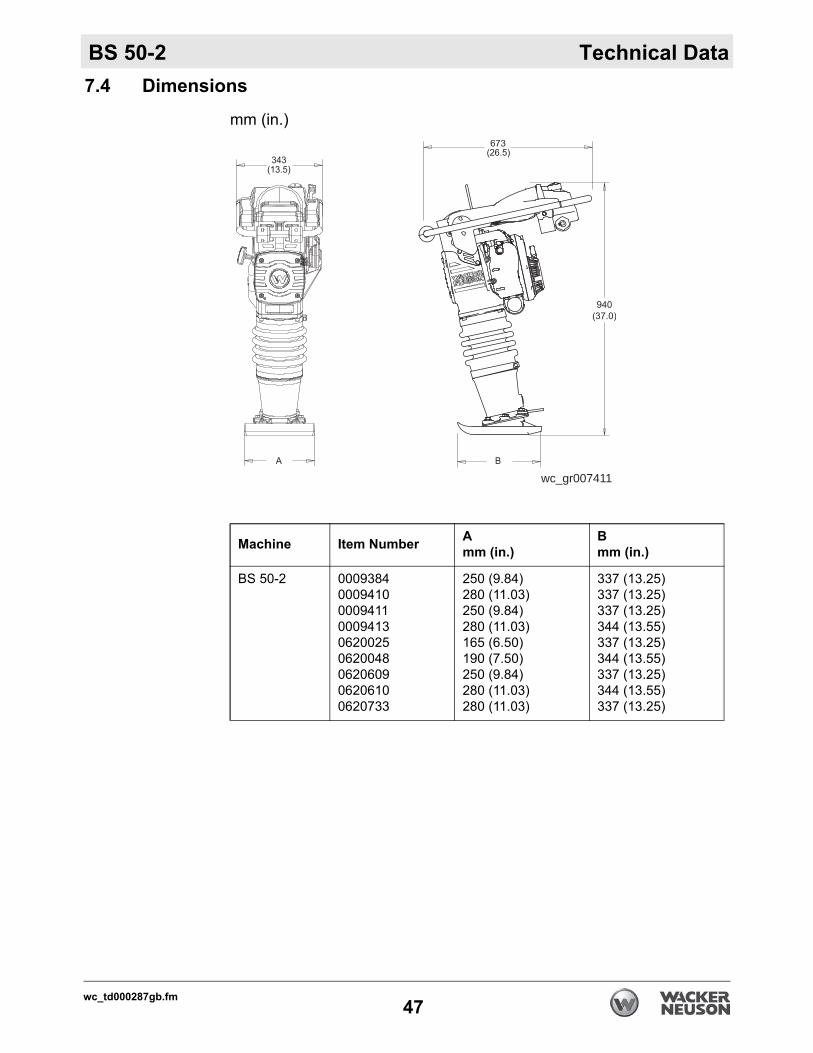
7.4 Dimensionsmm (in.)
wc_gr007411
Machine Item Number Amm (in.)
Bmm (in.)
BS 50-2 000938400094100009411000941306200250620048062060906206100620733
250 (9.84)280 (11.03)250 (9.84)280 (11.03)165 (6.50)190 (7.50)250 (9.84)280 (11.03)280 (11.03)
337 (13.25)337 (13.25)337 (13.25)344 (13.55)337 (13.25)344 (13.55)337 (13.25)344 (13.55)337 (13.25)
wc_td000287gb.fm47

Technical Data BS 50-2
Noteswc_td000287gb.fm48
Emission Control Systems Information and Warranty
8 Emission Control Systems Information and WarrantyThe Emission Control Warranty and associated information is valid only for the U.S.A., its territories, and Canada.
8.1 Emission Control System Background InformationIntroductionWacker Neuson spark-ignited engines/equipment must conform with applicable Environmental Protection Agency (EPA) emissions regulations. There are two types of emissions that fall under these regulations: 1) exhaust, and 2) evaporative. These regulations require that manufacturers warrant the emission control systems for defects in materials and workmanship.Furthermore, EPA regulations require all manufacturers to furnish written instructions describing how to operate and maintain the engines/equipment including the emission control systems. This information is provided with all Wacker Neuson engines/equipment at the time of purchase.
Exhaust EmissionsThe combustion process produces carbon monoxide, oxides of nitrogen, and hydrocarbons. Control of hydrocarbons and oxides of nitrogen is very important because, under certain conditions, they react to form photochemical smog when subjected to sunlight. Carbon monoxide does not react in the same way, but it is toxic.Wacker Neuson utilizes lean carburetor settings and other systems to reduce the emissions of carbon monoxide, oxides of nitrogen, and hydrocarbons.
Evaporative EmissionsEvaporative emissions are fuel emissions and generally include emissions that result from permeation of fuel through the fuel-system materials or from ventilation of the fuel system.Wacker Neuson utilizes low-permeation fuel lines and fuel tanks where applicable to reduce evaporative emissions.
Problems that may affect EmissionsIf any of the following symptoms arise, have the engine/equipment inspected and repaired by a Wacker Neuson dealer/service center.
Hard starting or stalling after startingRough idlingMisfiring or backfiring under loadAfterburning (backfiring)Presence of black exhaust smoke during operationHigh fuel consumption
wc_tx001768gb.fm49
Emission Control Systems Information and Warranty
Tampering and AlteringTampering with or altering the emission control system may increase emissions beyond the legal limit. If evidence of tampering is found, Wacker Neuson may deny a warranty claim. Among those acts that constitute tampering are:Removing or altering of any part of the air intake, fuel, or exhaust systems.Altering or defeating the speed-adjusting mechanism causing the engine to operate outside its design parameters.
8.2 Limited Defect Warranty for Wacker Neuson Emission Control Systems
The Emission Control Warranty is valid only for the U.S.A., its territories, and Canada. Wacker Neuson Sales Americas, LLC, N92 W15000 Anthony Avenue, Menomonee Falls, WI 53051, (hereinafter “Wacker Neuson”) warrants to the initial retail purchaser, and each subsequent owner, that this engine/equipment, including all parts of its emission control systems, have been designed, built, and equipped to conform at the time of initial sale to all applicable emission regulations of the U.S. Environmental Protection Agency (EPA), and that the engine/equipment is free of defects in materials and workmanship which would cause this engine/equipment to fail to conform to EPA regulations during its warranty period. Wacker Neuson is also liable for damages to other engine/equipment components caused by a failure of any warranted parts during the warranty period.
Limited Defect Warranty Period for Wacker Neuson Emission Control SystemsThe warranty period for this engine/equipment begins on the date of sale to the initial purchaser and continues for a minimum of two (2) years. For the warranty terms for your specific engine/equipment, visit wackerneuson.com.Any implied warranties are limited to the duration of this written warranty.
What is covered Wacker Neuson recommends the use of genuine Wacker Neuson parts, or the equivalent, whenever maintenance is performed. The use of replacement parts not equivalent to the original parts may impair the effectiveness of the engine/equipment emission controls systems. If such a replacement part is used in the repair or maintenance of the engine/equipment, assure yourself that such part is warranted by its manufacturer to be equivalent to the parts offered by Wacker Neuson in performance and durability. Furthermore, if such a replacement part is used in the repair or maintenance of the engine/equipment, and an authorized Wacker Neuson dealer/service center determines it is defective or causes a failure of a warranted part, the claim for repair of the engine/equipment may be denied. If the part in question is not related to the reason the engine/equipment requires repair, the claim will not be denied.For the components listed in the following table, an authorized Wacker Neuson dealer/service center will, at no cost to you, make the necessary diagnosis, repair, or replacement necessary to ensure that the engine/equipment complies with the
wc_tx001768gb.fm50
Emission Control Systems Information and Warranty
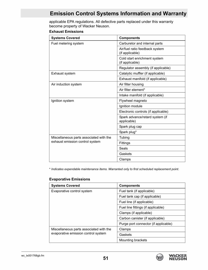
applicable EPA regulations. All defective parts replaced under this warranty become property of Wacker Neuson.Exhaust Emissions* Indicates expendable maintenance items. Warranted only to first scheduled replacement point.
Evaporative Emissions
Systems Covered ComponentsFuel metering system Carburetor and internal parts
Air/fuel ratio feedback system(if applicable)Cold start enrichment system (if applicable)Regulator assembly (if applicable)
Exhaust system Catalytic muffler (if applicable)Exhaust manifold (if applicable)
Air induction system Air filter housingAir filter element*Intake manifold (if applicable)
Ignition system Flywheel magnetoIgnition moduleElectronic controls (if applicable)Spark advance/retard system (if applicable)Spark plug capSpark plug*
Miscellaneous parts associated with the exhaust emission control system
TubingFittingsSealsGasketsClamps
Systems Covered ComponentsEvaporative control system Fuel tank (if applicable)
Fuel tank cap (if applicable)Fuel line (if applicable)Fuel line fittings (if applicable)Clamps (if applicable)Carbon canister (if applicable)Purge port connector (if applicable)
Miscellaneous parts associated with the evaporative emission control system
ClampsGasketsMounting brackets
wc_tx001768gb.fm51
Emission Control Systems Information and Warranty
What is not coveredFailures other than those resulting from defects in material or workmanship.Any systems or parts which are affected or damaged by owner abuse, tampering, neglect, improper maintenance, misuse, improper fueling, improper storage, accident and/or collision; the incorporation of, or any use of, add-on or modified parts, or unsuitable attachments, or the alteration of any part.Replacement of expendable maintenance items made in connection with required maintenance services after the item’s first scheduled replacement as listed in the maintenance section of the engine/equipment operator’s manual, such as spark plugs and filters.Incidental or consequential damages such as loss of time or the use of the engine/equipment, or any commercial loss due to the failure of the engine/equipment.Diagnosis and inspection charges that do not result in warranty-eligible service being performed.Any non-authorized replacement part, or malfunction of authorized parts due to use of-non authorized parts.
Owner’s Warranty ResponsibilityThe engine/equipment owner is responsible for the performance of the required maintenance listed in the Wacker Neuson engine/equipment operator’s manual. Wacker Neuson recommends that all receipts covering maintenance on the engine/equipment be retained, but Wacker Neuson cannot deny warranty coverage solely for the lack of receipts or for the failure to ensure the performance of all scheduled maintenance.Normal maintenance, replacement, or repair of emission control devices and systems may be performed by any repair establishment or individual; however, warranty repairs must be performed by an authorized Wacker Neuson dealer/service center. The engine/equipment must be presented to an authorized Wacker Neuson dealer/service center as soon as a problem exists. Contact Wacker Neuson Product Support Department (1-800-770-0957) or visit wackerneuson.com to find a dealer/service center in your area, or to answer questions regarding warranty rights and responsibilities.
How to Make a ClaimIn the event that any emission-related part is found to be defective during the warranty period, you shall notify Wacker Neuson Product Support Department (1-800-770-0957), and you will be advised of the appropriate dealer/service center where warranty repair can be performed. All repairs qualifying under this limited warranty must be performed by an authorized Wacker Neuson dealer/service center.You must take your Wacker Neuson engine/equipment along with proof of original purchase date, at your expense, to the authorized Wacker Neuson dealer/service center during their normal business hours.
wc_tx001768gb.fm52
Emission Control Systems Information and Warranty
For owners located more than 100 miles from an authorized dealer/service center (excluding the states with high-altitude areas as identified in 40 CFR Part 1068, Appendix III), Wacker Neuson will pay for pre-approved shipping costs to and from an authorized Wacker Neuson dealer/service center.Claims for repair or adjustment found to be caused solely by defects in material or workmanship will not be denied because the engine/equipment was not properly maintained and used.The warranty repairs should be completed in a reasonable amount of time, not to exceed 30 days.wc_tx001768gb.fm53

Emission Control Systems Information and Warranty
Notes:wc_tx001768gb.fm54


Wacker Neuson Produktion GmbH & Co. KG, Preußenstraße 41, D-80809 München, Tel.: +49-(0)89-3 54 02-0 Fax: +49 - (0)89-3 54 02-390Wacker Neuson Production Americas LLC, N92W15000 Anthony Ave., Menomonee Falls, WI 53051
Tel. : (262) 255-0500 Fax: (262) 255-0550 Tel.: (800) 770-0957Wacker Neuson Limited - Room 1701–03 & 1717–20, 17/F. Tower 1, Grand Century Place, 193 Prince Edward Road West, Mongkok, Kowloon, Hongkong.
Tel: (852) 3605 5360, Fax: (852) 2758 0032