Embed Size (px)
Citation preview
OPERATOR’SMANUAL
Model 104Batch Freezer
Original Operating Instructions
053064-M8/13/08 (Original Publication)
(Updated 8/3/15)

Complete this page for quick reference when service is required:
Taylor Distributor:
Address:
Phone:
Service:
Parts:
Date of Installation:
Information found on data plate:
Model Number:
Serial Number:
Electrical Specs: Voltage Cycle
Phase
Maximum Fuse Size: A
Minimum Wire Ampacity: A
E 2008 Carrier Commercial Refrigeration, Inc.053064-MAny unauthorized reproduction, disclosure, or distribution of copies by any person of any portion of this work may bea violation of Copyright Law of the United States of America and other countries, could result in the awarding of StatutoryDamages of up to $250,000 (17 USC 504) for infringement, and may result in further civil and criminal penalties.All rights reserved.
Taylor Companya division of Carrier Commercial Refrigeration, Inc.750 N. Blackhawk Blvd.Rockton, IL 61072

Table of Contents Model 104
Table of Contents
Section 1 To the Installer 1. . . . . . . . . . . . . . . . . . . . . . . . . . . . . . . . . . . . . . . . . . . .
Installer Safety 1. . . . . . . . . . . . . . . . . . . . . . . . . . . . . . . . . . . . . . . . . . . . . . . . . . . . . . . .
Site Preparation 1. . . . . . . . . . . . . . . . . . . . . . . . . . . . . . . . . . . . . . . . . . . . . . . . . . . . . . .
Air Cooled Units 2. . . . . . . . . . . . . . . . . . . . . . . . . . . . . . . . . . . . . . . . . . . . . . . . . . . . . . .
Electrical Connections 2. . . . . . . . . . . . . . . . . . . . . . . . . . . . . . . . . . . . . . . . . . . . . . . . .
Section 2 To the Operator 4. . . . . . . . . . . . . . . . . . . . . . . . . . . . . . . . . . . . . . . . . . .
Section 3 Safety 5. . . . . . . . . . . . . . . . . . . . . . . . . . . . . . . . . . . . . . . . . . . . . . . . . . . .
Section 4 Operator Parts Identification 7. . . . . . . . . . . . . . . . . . . . . . . . . . . . . . .
Model 104 7. . . . . . . . . . . . . . . . . . . . . . . . . . . . . . . . . . . . . . . . . . . . . . . . . . . . . . . . . . . .
Beater Door Assembly 8. . . . . . . . . . . . . . . . . . . . . . . . . . . . . . . . . . . . . . . . . . . . . . . . .
Accessories 9. . . . . . . . . . . . . . . . . . . . . . . . . . . . . . . . . . . . . . . . . . . . . . . . . . . . . . . . . .
Section 5 Important: To The Operator 10. . . . . . . . . . . . . . . . . . . . . . . . . . . . . . . .
Control Switch (Item 1) 10. . . . . . . . . . . . . . . . . . . . . . . . . . . . . . . . . . . . . . . . . . . . . . . . .
Orange Dial Light (Item 2) 10. . . . . . . . . . . . . . . . . . . . . . . . . . . . . . . . . . . . . . . . . . . . . .
Safety 10. . . . . . . . . . . . . . . . . . . . . . . . . . . . . . . . . . . . . . . . . . . . . . . . . . . . . . . . . . . . . . .
Timer Control (Item 3) 11. . . . . . . . . . . . . . . . . . . . . . . . . . . . . . . . . . . . . . . . . . . . . . . . .
Door Hinge (Item 4) 11. . . . . . . . . . . . . . . . . . . . . . . . . . . . . . . . . . . . . . . . . . . . . . . . . . .
Reset Condition 11. . . . . . . . . . . . . . . . . . . . . . . . . . . . . . . . . . . . . . . . . . . . . . . . . . . . . . .
Section 6 Operating Procedures 12. . . . . . . . . . . . . . . . . . . . . . . . . . . . . . . . . . . . .
Assembly 12. . . . . . . . . . . . . . . . . . . . . . . . . . . . . . . . . . . . . . . . . . . . . . . . . . . . . . . . . . . .
Sanitizing 15. . . . . . . . . . . . . . . . . . . . . . . . . . . . . . . . . . . . . . . . . . . . . . . . . . . . . . . . . . . .
Priming 16. . . . . . . . . . . . . . . . . . . . . . . . . . . . . . . . . . . . . . . . . . . . . . . . . . . . . . . . . . . . . .
Overrun 17. . . . . . . . . . . . . . . . . . . . . . . . . . . . . . . . . . . . . . . . . . . . . . . . . . . . . . . . . . . . . .
Drawing Product 18. . . . . . . . . . . . . . . . . . . . . . . . . . . . . . . . . . . . . . . . . . . . . . . . . . . . . .
Rinsing 18. . . . . . . . . . . . . . . . . . . . . . . . . . . . . . . . . . . . . . . . . . . . . . . . . . . . . . . . . . . . . .
Cleaning 19. . . . . . . . . . . . . . . . . . . . . . . . . . . . . . . . . . . . . . . . . . . . . . . . . . . . . . . . . . . . .
Disassembly 19. . . . . . . . . . . . . . . . . . . . . . . . . . . . . . . . . . . . . . . . . . . . . . . . . . . . . . . . . .
Brush Cleaning 19. . . . . . . . . . . . . . . . . . . . . . . . . . . . . . . . . . . . . . . . . . . . . . . . . . . . . . .

Table of Contents Model 104
Table of Contents - Page 2
Section 7 Important: Operator Checklist 21. . . . . . . . . . . . . . . . . . . . . . . . . . . . . .
During Cleaning and Sanitizing 21. . . . . . . . . . . . . . . . . . . . . . . . . . . . . . . . . . . . . . . . .
Troubleshooting Bacterial Count 21. . . . . . . . . . . . . . . . . . . . . . . . . . . . . . . . . . . . . . . .
Regular Maintenance Checks 21. . . . . . . . . . . . . . . . . . . . . . . . . . . . . . . . . . . . . . . . . . .
Winter Storage 21. . . . . . . . . . . . . . . . . . . . . . . . . . . . . . . . . . . . . . . . . . . . . . . . . . . . . . . .
Section 8 Troubleshooting Guide 22. . . . . . . . . . . . . . . . . . . . . . . . . . . . . . . . . . . .
Section 9 Parts Replacement Schedule 23. . . . . . . . . . . . . . . . . . . . . . . . . . . . . . .
Section 10 Limited Warranty on Equipment 24. . . . . . . . . . . . . . . . . . . . . . . . . . . .
Section 11 Limited Warranty on Parts 26. . . . . . . . . . . . . . . . . . . . . . . . . . . . . . . . .
Note: Continuing research results in steady improvements; therefore, informationin this manual is subject to change without notice.
Note: Only instructions originating from the factory or its authorized translationrepresentative(s) are considered to be the original set of instructions.
E 2008 Carrier Commercial Refrigeration, Inc. (Original Publication)Updated August, 2015053064-MAny unauthorized reproduction, disclosure, or distribution of copies by any person of any portion of this workmay be a violation of Copyright Law of the United States of America and other countries, could result in theawarding of Statutory Damages of up to $250,000 (17 USC 504) for infringement, and may result in furthercivil and criminal penalties.All rights reserved.
Taylor Companya division of Carrier Commercial Refrigeration, Inc.750 N. Blackhawk Blvd.Rockton, IL 61072

1Model 104 To the Installer
131122
Section 1 To the Installer
The following information has been included in themanual as safety and regulatory guidelines. Forcomplete installation instructions, please see theInstallation Checklist.
Installer Safety
In all areas of the world, equipment should beinstalled in accordance with existing local codes.Please contact your local authorities if you have anyquestions.
Care should be taken to ensure that all basic safetypractices are followed during the installation andservicing activities related to the installation andservice of Taylor equipment.
S Only authorized Taylor service personnelshould perform installation and repairs on theequipment.
S Authorized service personnel should consultOSHA Standard 29CFRI910.147 or theapplicable code of the local area for theindustry standards on lockout/tagoutprocedures before beginning any installationor repairs.
S Authorized service personnel must ensurethat the proper PPE is available and wornwhen required during installation and service.
S Authorized service personnelmust remove allmetal jewelry, rings, and watches beforeworking on electrical equipment.
The main power supply(s) to the freezer mustbe disconnected prior to performing any repairs.Failure to follow this instruction may result in personalinjury or death from electrical shock or hazardousmoving parts as well as poor performance or damageto the equipment.
Note: All repairs must be performed by anauthorized Taylor Service Technician.
This unit has many sharp edges that cancause severe injuries.
Site Preparation
Review the area the unit is to be installed in beforeuncrating the unit, making sure that all possiblehazards the user or equipment may come into havebeen addressed.
For Indoor UseOnly: This unit is designed to operateindoors, under normal ambient temperatures of70_-75_F (21_-24_C). The freezer has successfullyperformed in high ambient temperatures of104_(40_C) at reduced capacities.
This unit must NOT be installed in an areawhere a water jet or hose can be used. NEVER use awater jet or hose to rinse or clean the unit. Failure tofollow this instruction may result in electrocution.
This unit must be installed on a level surfaceto avoid the hazard of tipping. Extreme care should betaken in moving this equipment for any reason. Two ormore persons are required to safely move this unit.Failure to comply may result in personal injury orequipment damage.
The authorized installer should inspect the unit fordamage and promptly report any damage to the localauthorized Taylor distributor.
This piece of equipment is made in the USA and hasUSA sizes of hardware. All metric conversions areapproximate and vary in size.

2To the Installer Model 104
130319
Air Cooled Units
DO NOT obstruct air intake and discharge openings:
Air cooled units require a minimum of 3” (76 mm) ofclearance around all sides of the freezer to allow foradequate air flow across the condenser(s). Failure toallow adequate clearance can reduce the refrigerationcapacity of the freezer and possibly cause permanentdamage to the compressor.
Electrical Connections
In the United States, this equipment is intended to beinstalled in accordance with the National ElectricalCode (NEC), ANSI/NFPA70-1987. Thepurpose of theNEC code is the practical safeguardingof persons andproperty from hazards arising from the use ofelectricity. This code contains provisions considerednecessary for safety. In all other areas of the world,equipment should be installed in accordance with theexisting local codes. Please contact your localauthorities.
FOLLOW YOUR LOCAL ELECTRICAL CODES!
Each unit requires one power supply for each datalabel on the unit. Check the data label on the freezerfor branch circuit overcurrent protection or fuse, circuitampacity and other electrical specifications. Refer tothewiring diagramprovided insideof theelectrical box,for proper power connections.
CAUTION: THIS EQUIPMENT MUST BEPROPERLY GROUNDED! FAILURE TO DO SOCAN RESULT IN SEVERE PERSONAL INJURYFROM ELECTRICAL SHOCK!
This unit is provided with an equipotentialgrounding lug that is to be properly attached to the rearof the frameby the authorized installer. The installationlocation is marked by the equipotential bondingsymbol (5021 of IEC 60417-1) on both the removablepanel and the equipment’s frame.
S Stationary appliances which are not equippedwith a power cord anda plugor another deviceto disconnect the appliance from the powersource must have an all-pole disconnectingdevice with a contact gap of at least 3 mminstalled in the external installation.
S Appliances that are permanently connected tofixed wiring and for which leakage currentsmay exceed 10 mA, particularly whendisconnected, not used for long periods, orduring initial installation, shall have protectivedevices such as a GFI to protect against theleakage of current, installed by authorizedpersonnel to the local codes.
S Supply cords used with this unit shall beoil-resistant, sheathed flexible cable, notlighter than ordinary polychloroprene or otherequivalent synthetic elastomer-sheathed cord(Code designation 60245 IEC 57) installedwith the proper cord anchorage to relieveconductors from strain, including twisting, atthe terminals and protect the insulation of theconductors from abrasion.
If the supply cord is damaged, it must bereplaced by the manufacturer, its serviceagent, or similarly qualified person, in order toavoid a hazard.

3Model 104 To the Installer
130930
60 Cycle Units
This equipment is supplied with a 3- wire cord andgrounding type plug, for connection to a single phase,60 cycle, branch circuit supply. This unit must beplugged into a properly grounded receptacle.Permanent wiring may be employed, if required bylocal codes. Instructions for conversion to permanentwiring are as follows:
1. Be sure the freezer is electrically disconnected.
2. Remove the rear panel and locate the smallelectrical box at the base of the freezer.
3. Remove the factory installed cord and strainrelief bushing.
4. Route incoming permanent wiring through 7/8”(22 mm) hole in base pan.
5. Connect two power supply leads. Attach ground(earth) wire to the grounding lug inside theelectrical box.
6. Be sure the unit is properly grounded beforeapplying power.
Beater Rotation
Beater rotation must be clockwise as viewedlooking into the freezing cylinder.
To correct rotation on a three- phase unit, interchangeany two incoming power supply lines at freezer mainterminal block only.
To correct rotation on a single- phase unit, change theleads inside the beater motor. (Follow diagram printedon motor.)
Electrical connections are made directly to theterminal block. The terminal block is provided in theelectrical box located in the rear of the freezer.
Refrigerant
In consideration of our environment, Taylorproudly uses only earth friendly HFC refrigerants. TheHFC refrigerant used in this unit is R404A. Thisrefrigerant is generally considered non-toxic andnon-flammable, with an Ozone Depleting Potential(ODP) of zero (0).
However, any gas under pressure is potentiallyhazardous and must be handled with caution.
NEVER fill any refrigerant cylinder completely withliquid. Filling the cylinder to approximately 80% willallow for normal expansion.
Use only R404A refrigerant that conforms tothe AHRI standard 700 specification. The use of anyother refrigerant may expose users and operators tounexpected safety hazards.
Refrigerant liquid sprayed onto the skin maycause serious damage to tissue. Keep eyes and skinprotected. If refrigerant burns should occur, flushimmediately with cold water. If burns are severe, applyice packs and contact a physician immediately.
Taylor reminds technicians to be cautious ofgovernment laws regarding refrigerant recovery,recycling, and reclaiming systems. If you have anyquestions regarding these laws, please contact thefactory Service Department.
WARNING: R404A refrigerant used inconjunction with polyolester oils is extremely moistureabsorbent. When opening a refrigeration system, themaximum time the system is openmust not exceed 15minutes. Cap all open tubing to prevent humid air orwater from being absorbed by the oil.

4To the Operator Model 104
131122
Section 2 To the Operator
The freezer you have purchased has been carefullyengineered andmanufactured to give you dependableoperation. The Taylor Model 104 Batch Ice Creamfreezer, when properly operated and cared for, willproduce a consistent quality product. Like allmechanical products, this machine will requirecleaningandmaintenance. Aminimumamount of careand attention is necessary if the operating proceduresoutlined in this manual are followed closely.
This Operator’s Manual should be read beforeoperating or performing any maintenance on yourequipment.
Your Model 104 will NOT eventually compensate andcorrect for any errors during the set- up or fillingoperations. Thus, the initial assembly and primingprocedures are of extreme importance. It is stronglyrecommended that personnel responsible for theequipment’s operation, both assembly anddisassembly, go through these procedures together inorder to be properly trained and to make sure that nomisunderstandings exist.
In the event you should require technical assistance,please contact your local authorized TaylorDistributor.
Note: Your Taylor warranty is valid only if the parts areauthorized Taylor parts, purchased from the localauthorized Taylor Distributor, and only if all requiredservice work is provided by an authorized Taylorservice technician. Taylor reserves the right to denywarranty claims on units or parts if non- Taylorapproved parts or incorrect refrigerant were installedin the unit, system modifications were performedbeyond factory recommendations, or it is determinedthat the failure was caused by abuse, misuse, neglect,or failure to follow all operating instructions. For fulldetails of your Taylor Warranty, please see the LimitedWarranty section in this manual.
If the crossed out wheeled bin symbol isaffixed to this product, it signifies that this product iscompliant with the EUDirective as well as other similarlegislation in effect after August 13, 2005. Therefore,it must be collected separately after its use iscompleted, and cannot be disposed as unsortedmunicipal waste.
The user is responsible for returning the product to theappropriate collection facility, as specified by your localcode. For additional information regarding applicablelocal laws, please contact the municipal facility and/orlocal distributor.
Compressor Warranty Disclaimer
The refrigeration compressor(s) on this unit arewarranted for the term stated in the Limited Warrantysection in this manual. However, due to the MontrealProtocol and the U.S. Clean Air Act Amendments of1990, many new refrigerants are being tested anddeveloped, thus seeking their way into the serviceindustry. Some of these new refrigerants are beingadvertised as drop- in replacements for numerousapplications. It should be noted that in the event ofordinary service to this unit’s refrigeration system,only the refrigerant specified on the affixed datalabel should be used. The unauthorized use ofalternate refrigerants will void your Taylor compressorwarranty. It is the unit owner’s responsibility to makethis fact known to any technician he employs.
It should also be noted that Taylor does not warrant therefrigerant used in its equipment. For example, if therefrigerant is lost during the course of ordinary serviceto this machine, Taylor has no obligation to eithersupply or provide its replacement either at billable orunbillable terms. Taylor does have the obligation torecommend a suitable replacement if the originalrefrigerant is banned, obsoleted, or no longer availableduring the five year warranty of the compressor.
Taylor will continue to monitor the industry and testnew alternates as they are being developed. Should anew alternate prove, through our testing, that it wouldbe accepted as a drop- in replacement, then theabovedisclaimer would become null and void. To find out thecurrent status of an alternate refrigerant as it relates toyour compressor warranty, call the local TaylorDistributor or the Taylor Factory. Be prepared toprovide the Model/Serial Number of the unit inquestion.

5Model 104 Safety
130319
Section 3 SafetyWe, at Taylor Company, are concerned about thesafety of the operator at all times when they arecoming in contact with the unit and its parts. Taylormakes every effort to design and manufacture built- insafety features to protect both operators and servicetechnicians.
Installing and servicing refrigeration equipment can behazardous due to system pressure and electricalcomponents. Only trained and qualified servicepersonnel should install, repair, or service refrigerationequipment. When working on refrigeration equipment,observe precautions noted in the literature, tags andlabels attached to the unit, and other safetyprecautions that may apply. Follow all safety coderequirements. Wear safety glasses and work gloves.
IMPORTANT - Failure to adhere to thefollowing safety precautions may result in severepersonal injury or death. Failure to comply withthese warnings may damage the machine and itscomponents. Component damage will result inpart replacement expense and service repairexpense.
DONOT operate the freezer without readingthis Operator Manual. Failure to follow this instructionmay result in equipment damage, poor freezerperformance, health hazards, or personal injury.
This appliance is to be used only by trainedpersonnel. It is not intended for use by children orpeople with reduced physical, sensory, or mentalcapabilities, or lack of experience and knowledge,unless given supervision or instruction concerning theuse of the appliance by a person responsible for theirsafety. Children should be supervised to ensure thatthey do not play with the appliance.
DO NOT use a water jet to clean or rinse thefreezer. Failure to follow these instructions may resultin serious electrical shock.
S DO NOT operate the freezer unless it isproperly grounded.
S DO NOT operate the freezer with larger fusesthan specified on the data label.
S All repairs must be performed by anauthorized Taylor service technician.
S Themain power supplies to the machinemustbe disconnected prior to performing anyrepairs.
S For Cord Connected Units: Only Taylorauthorized service technicians or licensedelectricians may install a plug or replacementcord on this unit.
S Stationary appliances which are not equippedwith a power cord anda plugor another deviceto disconnect the appliance from the powersource must have an all-pole disconnectingdevice with a contact gap of at least 3 mminstalled in the external installation.
S Appliances that are permanently connected tofixed wiring and for which leakage currentsmay exceed 10 mA, particularly whendisconnected, not used for long periods, orduring initial installation, shall have protectivedevices such as a GFI to protect against theleakage of current and be installed byauthorized personnel to the local codes.
S Supply cords used with this unit shall beoil-resistant, sheathed, flexible cable, notlighter than ordinary polychloroprene or otherequivalent synthetic elastomer-sheathed cord(Code designation 60245 IEC 57) installedwith the proper cord anchorage to relieveconductors from strain, including twisting, atthe terminals and protect the insulation of theconductors from abrasion.
If the supply cord is damaged, it must bereplaced by the manufacturer, its serviceagent, or similarly qualified person, in order toavoid a hazard.
Failure to follow these instructions may result inelectrocution. Contact your local authorized TaylorDistributor for service.

6Safety Model 104
130319
This unit is provided with an equipotentialgrounding lug that is to be properly attached to the rearof the frameby the authorized installer. The installationlocation is marked by the equipotential bondingsymbol (5021 of IEC 60417-1) on both the removablepanel and the equipment’s frame.
S DONOT allow untrained personnel to operatethis machine.
S DONOT operate the freezer unless all servicepanels and access doors are restrained withscrews.
S DO NOT remove the door, beater or scraperblades unless the power switch is in the OFFposition.
Failure to follow these instructionsmay result in severepersonal injury to fingers or hands from hazardousmoving parts.
S DO NOT put objects or fingers in fill ordischarge openings. Failure to follow thisinstruction may result in contaminatedproduct or personal injury from blade contact.
S USE EXTREME CAUTION when removingthe beater assembly. The scraper blades arevery sharp and may cause injury.
Access to the service area of the unit isrestricted to persons having knowledge and practicalexperience with the appliance, in particular as far assafety and hygiene are concerned.
This freezer must be placed on a levelsurface. Failure to complymay result in personal injuryor equipment damage.
Cleaning and sanitizing schedules aregoverned by your Federal, State, or local regulatoryagencies and must be followed accordingly. Pleaserefer to the cleaning section of this manual for theproper procedure to clean this unit.
This machine is designed to maintain producttemperature under 41_F (5_C). Any product beingadded to this machine must be below 41_F (5_C).Failure to follow this instruction may result in healthhazards and poor freezer performance.
DO NOT operate the unit unless the freezerdoor is secured over the freezing cylinder.
DO NOT obstruct air intake and discharge openings:3” (76 mm) minimum air space around all sides.Failure to follow this instruction may cause poorfreezer performance and damage to the machine.
For Indoor UseOnly: This unit is designed to operateindoors, under normal ambient temperatures of70_-75_F (21_-24_C). The freezer has successfullyperformed in high ambient temperatures of104_(40_C) at reduced capacities.
DO NOT run the machine without product. Failure tofollow this instruction can result in damage to themachine.
NOISE LEVEL: Airborne noise emission does notexceed 78 dB(A) when measured at a distance of 1.0meter from the surface of the machine and at a heightof 1.6 meters from the floor.

7Model 104 Operator Parts Identification
Section 4 Operator Parts Identification
Model 104
Figure 1
ITEM DESCRIPTION PART NO.
1 FUNNEL 034252
2 PANEL- SIDE LEFT 051039
3 COVER A.- MIX INLET X24948
4 PANEL- REAR 051040
5 PANEL- SIDE RIGHT 051038
ITEM DESCRIPTION PART NO.
6 GASKET- BASE PAN 049420
7 PAN- DRIP 13- 1/4 LONG 039027
8 PANEL A.- FRONT X51043
9 STUD- FREEZER 023057
10 BEZEL 033406

8Operator Parts Identification Model 104
Beater Door Assembly
Figure 2
ITEM DESCRIPTION PART NO.
1 SEAL- DRIVE SHAFT 032560
2 SHAFT- BEATER 033498
3 BEATER ASSEMBLY X33417
4 BLADE- SCRAPER 7- 1/4” L 033277
5 O- RING 5- 7/16 OD X 5- 1/4 033276
6 DOOR A.- PARTIAL X37710
7 PIN A.- PIVOT 1- 3/4 GRIP X37705
8 SCREW- STEM 034662
ITEM DESCRIPTION PART NO.
9 SPOUT A.- DRIP X33422
10 NUT- STUD 008614
11 O- RING 2- 1/4 OD X .139 W 030890
12 PLATE- DRAW 027811
13 ARM- HANDLE 030042
14 PIN- QUICK RELEASE 3/16 027813
15 CAP- STEM 027812
16 STEM- FREEZER COVER 034661

9Model 104 Operator Parts Identification
110825
Accessories
Figure 3
ITEM DESCRIPTION PART NO.
1 PAIL-6 QT 023348
2 BRUSH-MIX PUMP BODY3” X 7”
023316
3 BRUSH-REAR BEARING1” X 2”
013071
ITEM DESCRIPTION PART NO.
4 BRUSH-DRAW VALVE 1-1/2” 014753
5 LUBRICANT-TAYLOR 4 OZ. 047518
6 SANITIZER-STERA SHEEN SEE NOTE
*Note: A sample container of sanitizer is sent with theunit. For reorders, order Stera Sheen part no. 055492(100 2 oz. packs) or Kay- 5 part no. 041082 (200 packs).

10Important: To The Operator Model 104
Section 5 Important: To The Operator
Figure 4
ITEM DESCRIPTION
1 CONTROL SWITCH
2 ORANGE DIAL LIGHT
3 TIMER CONTROL
4 DOOR HINGE
Control Switch (Item 1)
When the control switch is placed in the AUTO modeand the timer is adjusted to the desired setting, therefrigeration system will operate. When the switch isplaced in the EJECT mode, only the beater motor willoperate.
Orange Dial Light (Item 2)Locatedbelow the control switch is anorangedial light.When the control switch is in the AUTO position, thislight will come on, indicating the refrigeration systemis operable when the timer is set.
SafetyNEVER empty the contents of the freezing cylinderwhile the control switch is in the AUTO position.Always put the control switch into the EJECT positionwhendrawingproduct from the freezingcylinder. Asanadditional safety feature, this unit will NOT operate ifthe door is open.

11Model 104 Important: To The Operator
Timer Control (Item 3)The Model 104 uses a timer control to operate thecompressor and determine the viscosity of theproduct. After the desired amount of product has beenadded to the freezing cylinder, turn the timer for theamount of refrigeration required for the batch. Due tomix variations and desired finished product viscosity,the timer setting will vary.
Once the desired time is set, put the control switch intothe AUTO position. The compressor and beater motorwill operate until the time is up. When the timer settingelapses, the refrigerating process is cancelled. Thedial light and beater assembly will continue to operate.A tone will sound, signaling the operator to dispensethe finished product. Turn the control switch to theEJECT position. The product is ready to draw off andserve.
Start with five minutes and increase as needed. Timesand temperatures are dependent on specific mixformulations, pre- charge amounts and finishedproduct preferences.
Note: Because the freezing cylinder for the first batchis at room temperature, the first batch freeze- downtime will be longer than subsequent batches.
Door Hinge (Item 4)
This feature allows the operator to open the doorwithout removal. This feature is primarily used whenchanging flavors and clean- up is necessary.
Reset Condition
The Model 104 is equipped with an internal motoroverload protection. Should an overload occur, theresetmechanismwill trip, cancelling freezer operation.Toproperly reset the freezer, put the control switch intothe OFF position. Allow the beater motor to cool. Thenreturn the control switch to its original position.
Note: If the unit went out on reset, the product mayhave been run too cold or too long. Therefore, afterresetting the freezer, check the temperature control orthe time set.

12Operating Procedures Model 104
Section 6 Operating Procedures
TheModel 104 is a small 3 quart (2.9 liter) capacity icecream freezer. It has been designed to produce a richtasting, nominal overrun ice cream product that canbedrawn off and placed in a hardening cabinet or flashfreezer. Overrun can be varied depending on mixformulation, amount of pre- charge, and finishedproduct temperature.
We begin our instructions at the point where we findthe parts disassembled and laid out to air dry from theprevious brush cleaning.
The following procedures will show you how toassemble the parts into the freezer, sanitize them, andprime the freezer with fresh mix to prepare the firstbatch.
If you are disassembling the machine for the first timeor need information to get to this starting point in ourinstructions, turn to page 19, “Disassembly”, and startthere.
Assembly
Step 1
MAKESURECONTROLSWITCH IS INTHEOFF POSITION. Failure to do so may cause personalinjury or component damage.
Figure 5
Step 2Install the drive shaft. Lubricate the groove and shaftportion that comes in contact with the bearing on thebeater drive shaft. Slide the seal over the shaft andgroove until it snaps into place. DO NOT lubricate thehex endof thedrive shaft. Partially fill the insideportionof the seal with additional lubricant. Lubricate the flatside of the seal that comes in contact with the bearing.
Figure 6
Insert the drive shaft through the rear shell bearingandengage the hex end firmly into the gear box coupling.Be certain that the drive shaft fits into the couplingwithout binding.
Figure 7
13Model 104 Operating Procedures
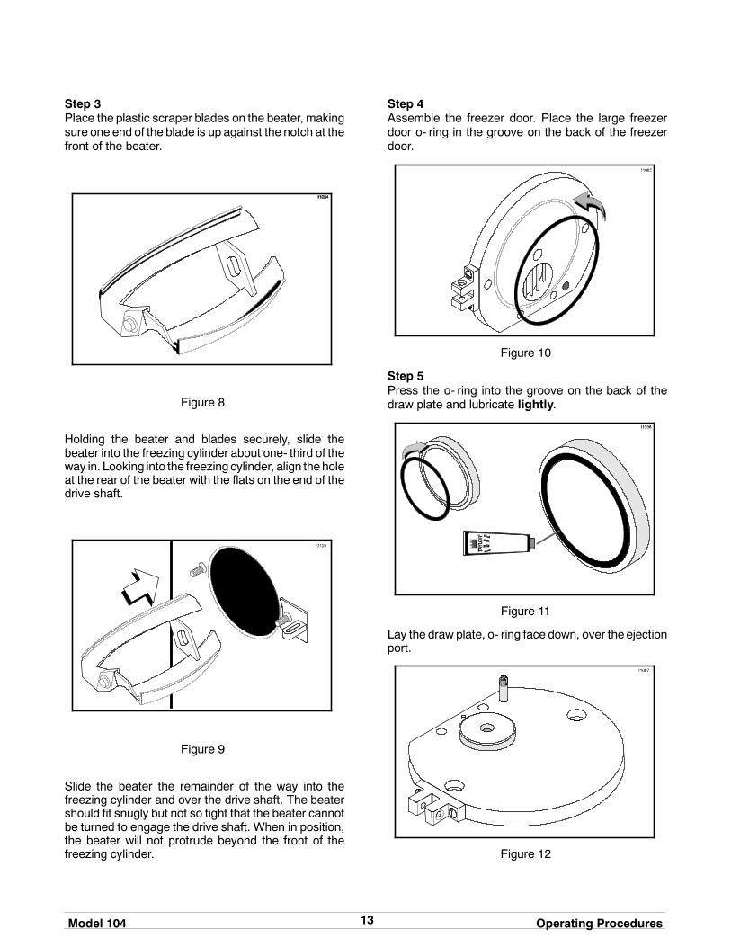
Step 3Place the plastic scraper blades on the beater, makingsure one end of the blade is up against the notch at thefront of the beater.
Figure 8
Holding the beater and blades securely, slide thebeater into the freezing cylinder about one- third of theway in. Looking into the freezing cylinder, align theholeat the rear of the beater with the flats on the end of thedrive shaft.
Figure 9
Slide the beater the remainder of the way into thefreezing cylinder and over the drive shaft. The beatershould fit snugly but not so tight that the beater cannotbe turned to engage the drive shaft. When in position,the beater will not protrude beyond the front of thefreezing cylinder.
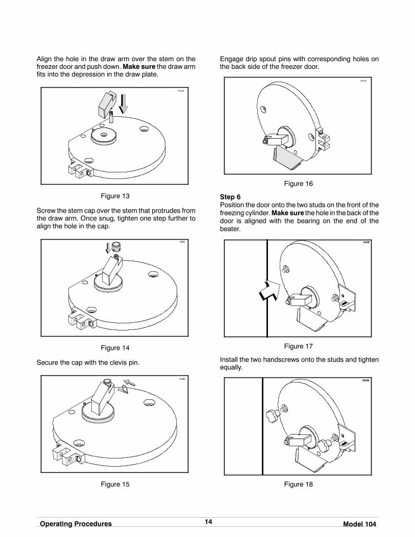
Step 4Assemble the freezer door. Place the large freezerdoor o- ring in the groove on the back of the freezerdoor.
Figure 10
Step 5Press the o- ring into the groove on the back of thedraw plate and lubricate lightly.
Figure 11
Lay the draw plate, o- ring face down, over theejectionport.
Figure 12
14Operating Procedures Model 104
Align the hole in the draw arm over the stem on thefreezer door and push down.Make sure the draw armfits into the depression in the draw plate.
Figure 13
Screw the stem cap over the stem that protrudes fromthe draw arm. Once snug, tighten one step further toalign the hole in the cap.
Figure 14
Secure the cap with the clevis pin.
Figure 15
Engage drip spout pins with corresponding holes onthe back side of the freezer door.
Figure 16
Step 6Position the door onto the two studs on the front of thefreezing cylinder.Make sure the hole in theback of thedoor is aligned with the bearing on the end of thebeater.
Figure 17
Install the two handscrews onto the studs and tightenequally.
Figure 18

15Model 104 Operating Procedures
Step 7Secure the freezer door hinge by installing the pivotpin.
Figure 19
Step 8Slide the drip pan into the hole in the front panel.
Figure 20
SanitizingStep 1Prepare two quarts (1.9 liters) of an approved 100PPM sanitizing solution (example: Kay- 5R or Stera-SheenR). USE WARM WATER AND FOLLOW THEMANUFACTURER’S SPECIFICATIONS.
Step 2Open the mix inlet cover on top of the freezer.
Figure 21
Sanitize your hands and the funnel. Install thefunnel into the mix inlet hole on top of the freezer.
Figure 22

16Operating Procedures Model 104
140717
Pour the sanitizing solution into the funnel and allow itto flow into the freezing cylinder.
Figure 23
Step 3Put the control switch into theEJECTposition. Thiswillcause the sanitizing solution in the freezing cylinder tobe agitated. Allow it to agitate for five minutes.
KEEP FINGERS OUT OF FILL ANDDISCHARGEOPENINGS! Failure to do somay resultin personal injury or component damage.
Figure 24
Step 4Put the control switch into the OFF position. Holding apail beneath the ejection port, open the draw arm anddrain the sanitizing solution from the freezing cylinder.Close the draw arm.
Figure 25
PrimingStep 1With the control switch in the OFF position, hold anempty pail beneath theejection port andopen thedrawarm.
KEEP FINGERS OUT OF FILL ANDDISCHARGEOPENINGS! Failure to do somay resultin personal injury or component damage.
Step 2Pour the desired amount of mix directly through thefunnel. The mix in the freezing cylinder will force outany remaining sanitizing solution. When full strengthmix is flowing from the ejection port, close the drawarm.
Figure 26

17Model 104 Operating Procedures
Step 3Set the timer for the time required for the batch. Allowthe unit to operate until the buzzer sounds and therefrigeration system automatically cycles off.
Figure 27
Step 4Place the control switch in theAUTOposition. Removethe funnel and close the mix inlet cover.
Figure 28
OverrunDepending on the overrun desired, the amount ofpre- charge can range from 1.5 to 3 quarts (1.4 to 2.8liters). This will give anoverrun between20% to100%.Overrun which exceeds 100% must not be takenbelow 26_F (- 3.3_C) or the product will not eject.Depending on the mix, product overrun below 100%may be taken as low as 18_F (- 7.7_C) with no ejectionproblem. If ejection problems do exist, it would beapparent that the product has been taken too cold.
Place the control switch in the EJECT position andtake a sample of the product to determine overrun. Ifthe overrun isnotat thedesired level, leave the controlswitch in theEJECT position to agitate the product andblend more air into the mixture. Continue to takesamples until the desired overrun is obtained.
Figure 29
Step 1Use a standard overrun scale and a one pintmeasuring cup.
Step 2Place the cup on the scale and adjust the scale pointerto the zero setting.
Figure 30

18Operating Procedures Model 104
Step 3Draw off one pint of frozen product, and with a straightedge, level off the top.
Figure 31
Step 4Place the pint of product on the scale and read theoverrun directly off of the scale.
Figure 32
Step 5If the scale does not have overrun graduations, thenweigh one pint of mix before freezing. Draw a samplepint of frozen product and level it off with a straightedge.
Step 6Place the pint of product on the scale and read theweight. Divide theweight of the frozen product into theweight of the rawmix for your percent of increase. If theanswer is 2, you have 100% overrun. If the answer isbetween1and 2, the decimal represents your overrun.
Example:1.85
8.2 15.2Raw Mix = 15.2 oz. (431 g)Frozen Mix = 8.2 oz. (232 g) Overrun = 85%
Drawing ProductStep 1When the desired temperature and overrun of theproduct has been achieved, the product may be drawninto packages or cans for hardening. Place thepackageor candirectly beneath the ejection port of thefreezer door.
Step 2Put the control switch into the EJECT position andopen thedrawarm. As theproduct is being ejected intothe container, ingredients such as fruits or nutsmay befolded into the container at the same time.
Step 3When the freezing cylinder is empty of product, closethe draw arm and put the control switch into the OFFposition. The container may now be placed in ahardening cabinet or flash freezer.
If the next batch to be run is not the same flavor, referto “Rinsing” on page 18 to clear the freezing cylinderof mix residue. Then repeat Priming, Overrun, andDrawing Procedures.
After the necessary batches have been prepared, themachine should be cleaned. The following procedureswill show you how to rinse the freezing cylinder of mixresidue, clean, and disassemble the parts from thefreezer. The machine should be sanitized at thebeginning of each day.
RinsingStep 1
BE SURE THE CONTROL SWITCH IS INTHE OFF POSITION. Failure to do so may causepersonal injury or component damage.
KEEP FINGERS OUT OF FILL ANDDISCHARGEOPENINGS! Failure to do somay resultin personal injury or component damage.
Step 2Open the mix inlet cover and install the funnel. Pourtwo quarts (1.9 liters) of cool, clean water into thefunnel and allow it to flow into the freezing cylinder.
Step 3Put the control switch into the EJECT position andallow the water to agitate for approximately oneminute.
19Model 104 Operating Procedures
140717
Step 4Put the control switch into the OFF position. Holding apail beneath the ejection port, open the draw arm anddrain the water from the freezing cylinder. Close thedraw arm.
Repeat these procedures until the rinse water beingdrawn from the freezing cylinder is clear.
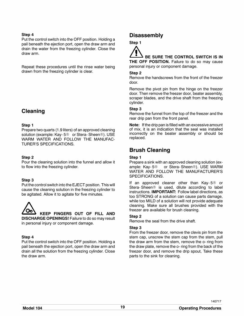
Cleaning
Step 1Prepare two quarts (1.9 liters) of an approved cleaningsolution (example: Kay- 5R or Stera- SheenR). USEWARM WATER AND FOLLOW THE MANUFAC-TURER’S SPECIFICATIONS.
Step 2Pour the cleaning solution into the funnel and allow itto flow into the freezing cylinder.
Step 3Put the control switch into theEJECTposition. Thiswillcause the cleaning solution in the freezing cylinder tobe agitated. Allow it to agitate for five minutes.
KEEP FINGERS OUT OF FILL ANDDISCHARGEOPENINGS! Failure to do somay resultin personal injury or component damage.
Step 4Put the control switch into the OFF position. Holding apail beneath the ejection port, open the draw arm anddrain all the solution from the freezing cylinder. Closethe draw arm.
DisassemblyStep 1
BE SURE THE CONTROL SWITCH IS INTHE OFF POSITION. Failure to do so may causepersonal injury or component damage.
Step 2Remove the handscrews from the front of the freezerdoor.
Remove the pivot pin from the hinge on the freezerdoor. Then remove the freezer door, beater assembly,scraper blades, and the drive shaft from the freezingcylinder.
Step 3Remove the funnel from the top of the freezer and therear drip pan from the front panel.
Note: If the drip pan is filled with an excessive amountof mix, it is an indication that the seal was installedincorrectly on the beater assembly or should bereplaced.
Brush CleaningStep 1Prepare a sink with an approved cleaning solution (ex-ample: Kay- 5R or Stera- SheenR). USE WARMWATER AND FOLLOW THE MANUFACTURER’SSPECIFICATIONS.
If an approved cleaner other than Kay- 5R orStera- SheenR is used, dilute according to labelinstructions. IMPORTANT: Follow label directions, astoo STRONG of a solution can cause parts damage,while too MILD of a solution will not provide adequatecleaning. Make sure all brushes provided with thefreezer are available for brush cleaning.
Step 2Remove the seal from the drive shaft.
Step 3From the freezer door, remove the clevis pin from thestem cap, unscrew the stem cap from the stem, pullthe draw arm from the stem, remove the o- ring fromthe draw plate, remove the o- ring from the back of thefreezer door, and remove the drip spout, Take theseparts to the sink for cleaning.
20Operating Procedures Model 104
Step 4Thoroughly brush clean all disassembled parts in thecleaning solution,making sure all lubricant andmix filmis removed. Place the cleaned parts on a clean drysurface to air dry.
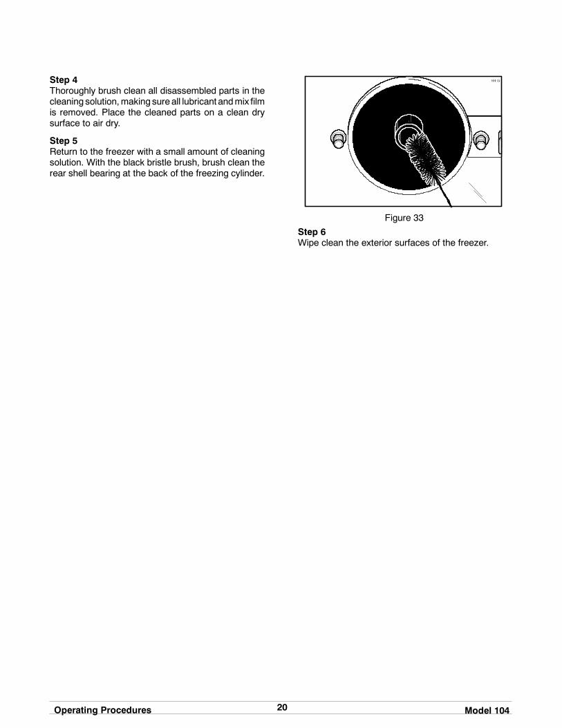
Step 5Return to the freezer with a small amount of cleaningsolution. With the black bristle brush, brush clean therear shell bearing at the back of the freezing cylinder.
Figure 33
Step 6Wipe clean the exterior surfaces of the freezer.

21Model 104 Important: Operator Checklist
Section 7 Important: Operator Checklist
During Cleaning and Sanitizing
ALWAYS FOLLOW LOCAL HEALTH CODES.
Cleaning and sanitizing schedules are governed byyour State or local regulatory agencies and must befollowed accordingly. The following check pointsshould be stressed during the cleaning and sanitizingoperations.
We recommend that after the necessary batcheshave been prepared for the day, the machineshould be cleaned. At the beginning of each daythe machine should be sanitized.
Troubleshooting Bacterial Countj 1. Thoroughly clean and sanitize the machine
regularly, including complete disassembly andbrush cleaning.
j 2. Use all brushes supplied for thorough cleaning.The brushes are specially designed to reach allmix passageways.
j 3. Use the white bristle brush to clean the mix inlethole which extends from the top down to therear of the freezing cylinder.
j 4. Use the black bristle brush to thoroughly cleanthe rear shell bearing located at the rear of thefreezing cylinder. Be sure to have a generousamount of cleaning solution on the brush.
j 5. Using a screwdriver and cloth towel, keep thefemale hex drive socket and rear shell bearingclean and free of lubricant and mix deposits.
j 6. Properly prepare the cleaning or sanitizingsolutions. Read and follow label directionscarefully. Too strong of a solution may damagethe parts and too weak of a solution will not doan adequate job of cleaning or sanitizing.
j 7. The temperature of liquidmix should not exceed40_F. (4.4_C.).
j 8. Follow your local health codes when usingflavorings, fruits, or nuts in this machine.
Regular Maintenance Checks
j 1. Check the rear shell bearing for signs of wear(excessive mix leakage in rear drip pan) and becertain it is properly cleaned.
j 2. Dispose of seals if they are worn, torn, or fit tooloosely, and replace with new ones.
j 3. Follow all lubricating procedures as outlined in“Assembly”.
j 4. Replace scraper blades that are damaged ornicked. Before installing the beater assembly,be certain that scraper blades are properlyattached to the beater assembly.
j 5. If your machine is air cooled, check thecondenser for accumulation of dirt and lint.Dirtycondensers will reduce the efficiency andcapacity of themachine. Condensers should becleaned monthly with a soft brush. Never usescrewdrivers or other metal probes to cleanbetween the fins.Note: For machines equipped with an air filter,it will be necessary to vacuum clean the filterson a monthly schedule.
Winter Storage
If the placeof business is to be closedduring thewintermonths, it is important to protect the freezer byfollowing certain precautions, particularly if thebuilding is to be left unheated and subject to freezingconditions.
Disconnect the freezer from the main power source toprevent possible electrical damage.
Wrap detachable parts of the freezer such as beater,blades, drive shaft, and freezer door, and place in aprotected dry place. Rubber trim parts and gasketscan be protected by wrapping with moisture- proofpaper. All parts should be thoroughly cleaned of driedmix or lubrication accumulations which attract miceand other vermin.

22Troubleshooting Guide Model 104
Section 8 Troubleshooting Guide
PROBLEM PROBABLE CAUSE REMEDY PAGEREF.
1. Poor ejection. a. Over refrigeration. a. Use less time to run thebatch.
- -
b. Inadequate pre- charge b. Increase the pre- charge. - -
c. The beater is rotatingcounterclockwise.
c. Contact service technicianto correct beater rotationto clockwise.
- -
2. No beater operation withthe control switch in theAUTO position.
a. The unit is unplugged. a. Plug into wall receptacle. - -
b. The circuit breaker is off,or the fuse is blown.
b. Turn the breaker on orreplace the fuse.
- -
c. The unit is out on reset. c. Put the freezer in the OFFposition. Allow the unit tocool. Resume normaloperation, but use lesstime to run the batch.
10
d. The freezer door is open. d. Secure the door forfreezer operation.
13
3. The product is notfreezing.
a. The timer control is notset or is defective.
a. Set time for required batchor contact servicetechnician to replace thetimer.
10
b. The condensers are dirtyon air cooled units.
b. Clean condensersmonthly.
21
c. The control switch is not inthe AUTO position.
c. Put the control switch intothe AUTO position forcompressor operation.
10
4. There is excessive mixleakage in the rear driptray.
a. The seal on the beaterdrive shaft is missing orworn.
a. Install or replace the sealon the beater drive shaft.
12 / 23
b. The rear shell bearing isworn.
b. Contact service technicianto replace the bearing.
- -
c. There is improperlubrication on the beaterdrive shaft.
c. Lubricate properly. 12
5. The buzzer does notsound when the unitcycles off.
a. The buzzer ismalfunctioning.
a. Contact service technicianto replace the buzzer.
- -

23Model 104 Parts Replacement Schedule
Section 9 Parts Replacement Schedule
PART DESCRIPTION EVERY 3MONTHS
EVERY 4MONTHS
EVERY 6MONTHS
ANNUALLY QTY.
Drive Shaft Seal X 1
Scraper Blades X Minimum 2
Freezer Door O- Ring X 1
Draw Plate O- Ring X 1
White Bristle Brush, 3” x 7” Inspect &Replace ifNecessary
Minimum 1
White Bristle Brush, 1- 1/2 x 2” Inspect &Replace ifNecessary
Minimum 1
Black Bristle Brush, 1” x 2” Inspect &Replace ifNecessary
Minimum 1

24Limited Warranty on Equipment Model 104
131122
Section 10 Limited Warranty on Equipment
TAYLOR COMPANY LIMITED WARRANTY ON FREEZERS
Taylor Company, a division of Carrier Commercial Refrigeration, Inc. (“Taylor”) is pleased to provide this limitedwarranty on new Taylor-branded freezer equipment available from Taylor to the market generally (the “Product”)to the original purchaser only.
LIMITED WARRANTY
Taylor warrants the Product against failure due to defect in materials or workmanship under normal use andservice as follows. All warranty periods begin on the date of original Product installation. If a part fails due todefect during the applicable warranty period, Taylor, through an authorized Taylor distributor or service agency,will provide a new or re- manufactured part, at Taylor’s option, to replace the failed defective part at no charge forthe part. Except as otherwise stated herein, these are Taylor’s exclusive obligations under this limited warranty fora Product failure. This limited warranty is subject to all provisions, conditions, limitations and exclusions listedbelow and on the reverse (if any) of this document.
Product Part Limited Warranty Period
Soft ServeFrozen YogurtShakesSmoothies
Frozen BeverageBatch Desserts
Insulated shell assembly Five (5) years
Refrigeration compressor(except service valve)
Five (5) years
Beater motors Two (2) years
Beater drive gear Two (2) years
Printed circuit boards andSoftech controls beginningwith serial number H8024200
Two (2) years
Parts not otherwise listed inthis table or excluded below
One (1) year
LIMITED WARRANTY CONDITIONS
1. If the date of original installation of the Product cannot be verified, then the limited warranty period beginsninety (90) days from the date of Product manufacture (as indicated by the Product serial number). Proof ofpurchase may be required at time of service.
2. This limited warranty is valid only if the Product is installed and all required service work on the Product isperformed by an authorized Taylor distributor or service agency, and only if genuine, new Taylor parts areused.
3. Installation, use, care, and maintenance must be normal and in accordance with all instructions contained inthe Taylor Operator’s Manual.
4. Defective parts must be returned to the authorized Taylor distributor or service agency for credit.
5. The use of any refrigerant other than that specified on the Product’s data label will void this limited warranty.
LIMITED WARRANTY EXCEPTIONS
This limited warranty does not cover:
1. Labor or other costs incurred for diagnosing, repairing, removing, installing, shipping, servicing or handling ofdefective parts, replacement parts, or new Products.
2. Normal maintenance, cleaning and lubrication as outlined in the Taylor Operator’s Manual, including cleaningof condensers.

25Model 104 Limited Warranty on Equipment
3. Replacement of wear items designated as Class “000” parts in the Taylor Operator’s Manual.
4. External hoses, electrical power supplies, and machine grounding.
5. Parts not supplied or designated by Taylor, or damages resulting from their use.
6. Return trips or waiting time required because a service technician is prevented from beginning warrantyservice work promptly upon arrival.
7. Failure, damage or repairs due to faulty installation, misapplication, abuse, no or improper servicing,unauthorized alteration or improper operation or use as indicated in the Taylor Operator’s Manual, includingbut not limited to the failure to use proper assembly and cleaning techniques, tools, or approved cleaningsupplies.
8. Failure, damage or repairs due to theft, vandalism, wind, rain, flood, high water, water, lightning, earthquakeor any other natural disaster, fire, corrosive environments, insect or rodent infestation, or other casualty,accident or condition beyond the reasonable control of Taylor; operation above or below the electrical orwater supply specification of the Product; or components repaired or altered in any way so as, in thejudgment of the Manufacturer, to adversely affect performance, or normal wear or deterioration.
9. Any Product purchased over the Internet.
10. Failure to start due to voltage conditions, blown fuses, open circuit breakers, or damages due to theinadequacy or interruption of electrical service.
11. Electricity or fuel costs, or increases in electricity or fuel costs from any reason whatsoever.
12. Damages resulting from the use of any refrigerant other than that specified on the Product’s data label willvoid this limited warranty.
13. Any cost to replace, refill or dispose of refrigerant, including the cost of refrigerant.
14. ANY SPECIAL, INDIRECT OR CONSEQUENTIAL PROPERTY OR COMMERCIAL DAMAGE OF ANYNATURE WHATSOEVER. Some jurisdictions do not allow the exclusion of incidental or consequentialdamages, so this limitation may not apply to you.
This limited warranty gives you specific legal rights, and you may also have other rights which vary fromjurisdiction to jurisdiction.
LIMITATION OF WARRANTY
THIS LIMITED WARRANTY IS EXCLUSIVE AND IS IN LIEU OF ALL OTHER WARRANTIES, CONDITIONSAND/OR REMEDIES UNDER THE LAW, INCLUDING ANY IMPLIED WARRANTIES OR CONDITIONS OFMERCHANTABILITY OR FITNESS FOR A PARTICULAR PURPOSE. THE ORIGINAL OWNER’S SOLEREMEDY WITH RESPECT TO ANY PRODUCTS SHALL BE REPAIR OR REPLACEMENT OF DEFECTIVECOMPONENTS UNDER THE TERMS OF THIS LIMITED WARRANTY. ALL RIGHTS TO CONSEQUENTIALOR INCIDENTAL DAMAGES (INCLUDING CLAIMS FOR LOST SALES, LOST PROFITS, PRODUCT LOSS,PROPERTY DAMAGES OR SERVICE EXPENSES) ARE EXPRESSLY EXCLUDED. THE EXPRESSWARRANTIES MADE IN THIS LIMITED WARRANTY MAY NOT BE ALTERED, ENLARGED, OR CHANGEDBY ANY DISTRIBUTOR, DEALER, OR OTHER PERSON, WHATSOEVER.
LEGAL REMEDIES
The owner must notify Taylor in writing, by certified or registered letter to the following address, of any defect orcomplaint with the Product, stating the defect or complaint and a specific request for repair, replacement, or othercorrection of the Product under warranty, mailed at least thirty (30) days before pursuing any legal rights orremedies.
Taylor Companya division of Carrier Commercial Refrigeration, Inc.
750 N. Blackhawk Blvd.Rockton, IL 61072, U.S.A.

26Limited Warranty on Parts Model 104
131122
Section 11 Limited Warranty on Parts
TAYLOR COMPANY LIMITED WARRANTY ON TAYLOR GENUINE PARTS
Taylor Company, a division of Carrier Commercial Refrigeration, Inc. (“Taylor”) is pleased to provide this limitedwarranty on new Taylor genuine replacement components and parts available from Taylor to the market generally(the “Parts”) to the original purchaser only.
LIMITED WARRANTY
Taylor warrants the Parts against failure due to defect in materials or workmanship under normal use and serviceas follows. All warranty periods begin on the date of original installation of the Part in the Taylor unit. If a Part failsdue to defect during the applicable warranty period, Taylor, through an authorized Taylor distributor or serviceagency, will provide a new or re- manufactured Part, at Taylor’s option, to replace the failed defective Part at nocharge for the Part. Except as otherwise stated herein, these are Taylor’s exclusive obligations under this limitedwarranty for a Part failure. This limited warranty is subject to all provisions, conditions, limitations and exclusionslisted below and on the reverse (if any) of this document.
Part’s Warranty Class Code or Part Limited Warranty Period
Class 103 Parts¹ Three (3) months
Class 212 Parts² Twelve (12) months
Class 512 Parts Twelve (12) months
Class 000 Parts No warranty
Taylor Part #072454 (Motor- 24VDC *C832/C842*) Four (4) years
LIMITED WARRANTY CONDITIONS
1. If the date of original installation of the Part cannot be otherwise verified, proof of purchase may be requiredat time of service.
2. This limited warranty is valid only if the Part is installed and all required service work in connection with thePart is performed by an authorized Taylor distributor or service agency.
3. The limited warranty applies only to Parts remaining in use by their original owner at their original installationlocation in the unit of original installation.
4. Installation, use, care, and maintenance must be normal and in accordance with all instructions contained inthe Taylor Operator’s Manual.
5. Defective Parts must be returned to the authorized Taylor distributor or service agency for credit.
6. This warranty is not intended to shorten the length of any warranty coverage provided pursuant to a separateTaylor Limited Warranty on freezer or grill equipment.
7. The use of any refrigerant other than that specified for the unit in which the Part is installed will void thislimited warranty.
1, 2 Except that Taylor Part #032129SER2 (Compressor-Air-230V SERV) and Taylor Part #075506SER1(Compressor-Air-115V 60HZ) shall have a limited warranty period of twelve (12) months when used in Taylorfreezer equipment and a limited warranty period of two (2) years when used in Taylor grill equipment.

27Model 104 Limited Warranty on Parts
LIMITED WARRANTY EXCEPTIONS
This limited warranty does not cover:
1. Labor or other costs incurred for diagnosing, repairing, removing, installing, shipping, servicing or handling ofdefective Parts, replacement Parts, or new Parts.
2. Normal maintenance, cleaning and lubrication as outlined in the Taylor Operator’s Manual, including cleaningof condensers or carbon and grease buildup.
3. Required service, whether cleaning or general repairs, to return the cooking surface assemblies, includingthe upper platen and lower plate, to an operational condition to achieve proper cooking or allow properassembly of release sheets and clips as a result of grease build-up on the cooking surfaces, including butnot limited to the platen and plate, sides of the shroud or top of the shroud.
4. Replacement of cooking surfaces, including the upper platen and lower plate, due to pitting or corrosion (orin the case of the upper platen, due to loss of plating) as a result of damage due to the impact of spatulas orother small wares used during the cooking process or as a result of the use of cleaners, cleaning materialsor cleaning processes not approved for use by Taylor.
5. Replacement of wear items designated as Class “000” Parts in the Taylor Operator’s Manual, as well as anyrelease sheets and clips for the Product’s upper platen assembly.
6. External hoses, electrical power supplies, and machine grounding.
7. Parts not supplied or designated by Taylor, or damages resulting from their use.
8. Return trips or waiting time required because a service technician is prevented from beginning warrantyservice work promptly upon arrival.
9. Failure, damage or repairs due to faulty installation, misapplication, abuse, no or improper servicing,unauthorized alteration or improper operation or use as indicated in the Taylor Operator’s Manual, includingbut not limited to the failure to use proper assembly and cleaning techniques, tools, or approved cleaningsupplies.
10. Failure, damage or repairs due to theft, vandalism, wind, rain, flood, high water, water, lightning, earthquakeor any other natural disaster, fire, corrosive environments, insect or rodent infestation, or other casualty,accident or condition beyond the reasonable control of Taylor; operation above or below the gas, electrical orwater supply specification of the unit in which a part is installed; or Parts or the units in which they areinstalled repaired or altered in any way so as, in the judgment of Taylor, to adversely affect performance, ornormal wear or deterioration.
11. Any Part purchased over the Internet.
12. Failure to start due to voltage conditions, blown fuses, open circuit breakers, or damages due to theinadequacy or interruption of electrical service.
13. Electricity, gas or other fuel costs, or increases in electricity or fuel costs from any reason whatsoever.
14. Damages resulting from the use of any refrigerant other than that specified for the unit in which the Part isinstalled will void this limited warranty.
15. Any cost to replace, refill or dispose of refrigerant, including the cost of refrigerant.
16. ANY SPECIAL, INDIRECT OR CONSEQUENTIAL PROPERTY OR COMMERCIAL DAMAGE OF ANYNATURE WHATSOEVER. Some jurisdictions do not allow the exclusion of incidental or consequentialdamages, so this limitation may not apply to you.
This limited warranty gives you specific legal rights, and you may also have other rights which vary fromjurisdiction to jurisdiction.

28Limited Warranty on Parts Model 104
LIMITATION OF WARRANTY
THIS LIMITED WARRANTY IS EXCLUSIVE AND IS IN LIEU OF ALL OTHER WARRANTIES, CONDITIONSAND/OR REMEDIES UNDER THE LAW, INCLUDING ANY IMPLIED WARRANTIES OR CONDITIONS OFMERCHANTABILITY OR FITNESS FOR A PARTICULAR PURPOSE. THE ORIGINAL OWNER’S SOLEREMEDY WITH RESPECT TO ANY PRODUCTS SHALL BE REPAIR OR REPLACEMENT OF DEFECTIVEPARTS UNDER THE TERMS OF THIS LIMITED WARRANTY. ALL RIGHTS TO CONSEQUENTIAL ORINCIDENTAL DAMAGES (INCLUDING CLAIMS FOR LOST SALES, LOST PROFITS, PRODUCT LOSS,PROPERTY DAMAGES OR SERVICE EXPENSES) ARE EXPRESSLY EXCLUDED. THE EXPRESSWARRANTIES MADE IN THIS LIMITED WARRANTY MAY NOT BE ALTERED, ENLARGED, OR CHANGEDBY ANY DISTRIBUTOR, DEALER, OR OTHER PERSON, WHATSOEVER.
LEGAL REMEDIES
The owner must notify Taylor in writing, by certified or registered letter to the following address, of any defect orcomplaint with the Part, stating the defect or complaint and a specific request for repair, replacement, or othercorrection of the Part under warranty, mailed at least thirty (30) days before pursuing any legal rights or remedies.
Taylor Companya division of Carrier Commercial Refrigeration, Inc.
750 N. Blackhawk Blvd.Rockton, IL 61072, U.S.A.